Embed Size (px)
Citation preview
User Manual
AIMB-281
Intel® Xeon E3/ Core™ i7/i5/i3/Celeron LGA1155 Mini-ITX with CRT/DVI/LVDS, 6 COM, Dual LAN, PCIe x4

CopyrightThe documentation and the software included with this product are copyrighted 2014by Advantech Co., Ltd. All rights are reserved. Advantech Co., Ltd. reserves the rightto make improvements in the products described in this manual at any time withoutnotice.
No part of this manual may be reproduced, copied, translated or transmitted in anyform or by any means without the prior written permission of Advantech Co., Ltd.Information provided in this manual is intended to be accurate and reliable. However,Advantech Co., Ltd. assumes no responsibility for its use, nor for any infringementsof the rights of third parties, which may result from its use.
AcknowledgementsIBM and PC are trademarks of International Business Machines Corporation.
Intel® Core™ i7/i5/i3, Pentium®, Celeron® is trademark of Intel CorporationWinBond is a trademark of Winbond Corporation.
All other product names or trademarks are properties of their respective owners.
Part No. 2006028100 Edition 1
Printed in China January 2014
AIMB-281 User Manual ii

A Message to the Customer
Advantech Customer Services
Each and every Advantech product is built to the most exacting specifications toensure reliable performance in the harsh and demanding conditions typical of indus-trial environments. Whether your new Advantech equipment is destined for the labo-ratory or the factory floor, you can be assured that your product will provide thereliability and ease of operation for which the name Advantech has come to beknown.
Your satisfaction is our primary concern. Here is a guide to Advantech’s customerservices. To ensure you get the full benefit of our services, please follow the instruc-tions below carefully.
Technical Support
We want you to get the maximum performance from your products. So if you run intotechnical difficulties, we are here to help. For the most frequently asked questions,you can easily find answers in your product documentation. These answers are nor-mally a lot more detailed than the ones we can give over the phone.
So please consult this manual first. If you still cannot find the answer, gather all theinformation or questions that apply to your problem, and with the product close athand, call your dealer. Our dealers are well trained and ready to give you the supportyou need to get the most from your Advantech products. In fact, most problemsreported are minor and are able to be easily solved over the phone.
In addition, free technical support is available from Advantech engineers every busi-ness day. We are always ready to give advice on application requirements or specificinformation on the installation and operation of any of our products.
iii AIMB-281 User Manual
Declaration of Conformity
FCC Class B
This device complies with the requirements in part 15 of the FCC rules:
Operation is subject to the following two conditions:
This device may not cause harmful interference This device must accept any interference received, including interference that
may cause undesired operation.This equipment has been tested and found to comply with the limits for a Class B dig-ital device, pursuant to Part 15 of the FCC Rules. These limits are designed to pro-vide reasonable protection against harmful interference when the equipment isoperated in a commercial environment. This equipment generates, uses, and canradiate radio frequency energy and, if not installed and used in accordance with theinstruction manual, may cause harmful interference to radio communications. Opera-tion of this device in a residential area is likely to cause harmful interference in whichcase the user will be required to correct the interference at his/her own expense. Theuser is advised that any equipment changes or modifications not expressly approvedby the party responsible for compliance would void the compliance to FCC regula-tions and therefore, the user's authority to operate the equipment.
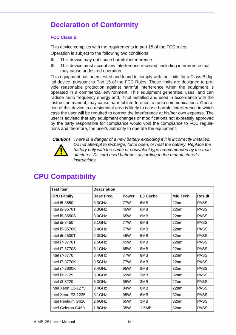
CPU Compatibility
Caution! There is a danger of a new battery exploding if it is incorrectly installed. Do not attempt to recharge, force open, or heat the battery. Replace the battery only with the same or equivalent type recommended by the man-ufacturer. Discard used batteries according to the manufacturer's instructions.
Test Item Description
CPU Family Base Freq Power L3 Cache Mfg Tech Result
Intel i5-3550 3.3GHz 77W 6MB 22nm PASS
Intel i5-3570T 2.3GHz 45W 6MB 22nm PASS
Intel i5-3550S 3.0GHz 65W 6MB 22nm PASS
Intel i5-3450 3.1GHz 77W 6MB 22nm PASS
Intel i5-3570K 3.4GHz 77W 6MB 22nm PASS
Intel i5-2500T 2.3GHz 45W 6MB 32nm PASS
Intel i7-3770T 2.5GHz 45W 8MB 22nm PASS
Intel i7-3770S 3.1GHz 65W 8MB 22nm PASS
Intel i7-3770 3.4GHz 77W 8MB 22nm PASS
Intel i7-3770K 3.5GHz 77W 8MB 22nm PASS
Intel i7-2600K 3.4GHz 95W 8MB 32nm PASS
Intel i3-2125 3.3GHz 65W 3MB 32nm PASS
Intel i3-3220 3.3GHz 55W 3MB 22nm PASS
Intel Xeon E3-1275 3.4GHz 84W 8MB 22nm PASS
Intel Xeon E3-1225 3.1GHz 95W 6MB 32nm PASS
Intel Pentium G620 2.6GHz 65W 3MB 32nm PASS
Intel Celeron G460 1.8GHz 35W 1.5MB 32nm PASS
AIMB-281 User Manual iv
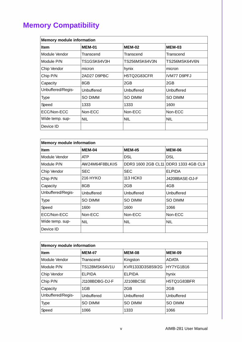
Memory Compatibility
Memory module information
Item MEM-01 MEM-02 MEM-03
Module Vendor Transcend Transcend Transcend
Module P/N TS1GSK64V3H TS256MSK64V3N TS256MSK64V6N
Chip Vendor micron hynix micron
Chip P/N 2AD27 D9PBC H5TQ2G83CFR IVM77 D9PFJ
Capacity 8GB 2GB 2GB
Unbuffered/Regis- Unbuffered Unbuffered Unbuffered
Type SO DIMM SO DIMM SO DIMM
Speed 1333 1333 1600
ECC/Non-ECC Non-ECC Non-ECC Non-ECC
Wide temp. sup- NIL NIL NIL
Device ID
Memory module information
Item MEM-04 MEM-05 MEM-06
Module Vendor ATP DSL DSL
Module P/N AW24M64F8BLK0S DDR3 1600 2GB CL11 DDR3 1333 4GB CL9
Chip Vendor SEC SEC ELPIDA
Chip P/N 216 HYKO 113 HCK0 J4208BASE-DJ-F
Capacity 8GB 2GB 4GB
Unbuffered/Regis- Unbuffered Unbuffered Unbuffered
Type SO DIMM SO DIMM SO DIMM
Speed 1600 1600 1066
ECC/Non-ECC Non-ECC Non-ECC Non-ECC
Wide temp. sup- NIL NIL NIL
Device ID
Memory module information
Item MEM-07 MEM-08 MEM-09
Module Vendor Transcend Kingston ADATA
Module P/N TS128MSK64V1U KVR1333D3S8S9/2G HY7YG1B16
Chip Vendor ELPIDA ELPIDA hynix
Chip P/N J1108BDBG-DJ-F J2108BCSE H5TQ1G83BFR
Capacity 1GB 2GB 2GB
Unbuffered/Regis- Unbuffered Unbuffered Unbuffered
Type SO DIMM SO DIMM SO DIMM
Speed 1066 1333 1066
v AIMB-281 User Manual

ECC/Non-ECC Non-ECC Non-ECC Non-ECC
Wide temp. sup- NIL NIL NIL
Device ID SD3-039/040 SD3-126/127 SD3-087/088
Memory module information
Item MEM-10 MEM-11 MEM-12
Module Vendor Innodisk Innodisk Transcend
Module P/N M3SP-2GMJCL0C-M M3SP-4GMJDL0C-M JM1333KSN-2G
Chip Vendor micron micron SpecTek
Chip P/N IQM22 D9PFJ IIM22 D9PFJ PE901
Capacity 2GB 4GB 2GB
Unbuffered/Regis- Unbuffered Unbuffered Unbuffered
Type SO DIMM SO DIMM SO DIMM
Speed 1600 1600 1333
ECC/Non-ECC Non-ECC Non-ECC Non-ECC
Wide temp. sup- NIL NIL NIL
Device ID SD3-142/143 SD3-145/146 SD3-116/117
Memory module information
Item MEM-13 MEM-14 MEM-15
Module Vendor DSL Panram ADATA
Module P/N DDR3 1333 2GB CL9 200D38G328,NB,K2BASESF
EL73I1B0873ZV
Chip Vendor ELPIDA ELPIDA
Chip P/N J1108BDSE-DJ-F F140X8A09481 J2108BCSE-DJ-F
Capacity 2GB 8GB 2GB
Unbuffered/Regis- Unbuffered Unbuffered Unbuffered
Type SO DIMM SO DIMM SO DIMM
Speed 1333 1333 1333
ECC/Non-ECC Non-ECC Non-ECC Non-ECC
Wide temp. sup- NIL NIL NIL
Device ID SD3-019/020 SD3-140/141 SD3-132/133
Memory module information
Item MEM-16 MEM-17 MEM-18
Module Vendor Kingston pqi Apacer
Module P/N KVR1066D3S7/1G MFCBR502SA0101 78.A2GC3.421
Chip Vendor Kingston hynix ELPIDA
Chip P/N D1288JPNDPLD9U H5TQ2G83AFR J1108BDBG-DJ-F
Capacity 1GB 4GB 2GB
Unbuffered/Regis- Unbuffered Unbuffered Unbuffered
AIMB-281 User Manual vi

Type SO DIMM SO DIMM SO DIMM
Speed 1066 1066 1066
ECC/Non-ECC Non-ECC Non-ECC Non-ECC
Wide temp. sup- NIL NIL NIL
Device ID SD3-064/065 SD3-075/076 SD3-027/028
Memory module information
Item MEM-19 MEM-20 MEM-21
Module Vendor Kingston hynix Transcend
Module P/N KVR1333D3S9/1G HMT112S6TFR8C-H9 TS512MSK64V1N
Chip Vendor Kingston hynix hynix
Chip P/N D1288JPNDPLD9U H5TQ1G83TFR H5TQ2G83BFR
Capacity 1GB 1GB 4GB
Unbuffered/Regis- Unbuffered Unbuffered Unbuffered
Type SO DIMM SO DIMM SO DIMM
Speed 1333 1333 1066
ECC/Non-ECC Non-ECC Non-ECC Non-ECC
Wide temp. sup- NIL NIL NIL
Device ID SD3-066/067 SD3-128/129 SD3-055/056
Memory module information
Item MEM-22 MEM-23 MEM-24
Module Vendor Transcend pqi ADATA
Module P/N TS256MSK64V6N MFCBR402PA0105 AD73I1A0873EG
Chip Vendor micron hynix ADATA
Chip P/N IVM77 D9PFJ H5TQ1G83BFR AD3BC8A-13339H
Capacity 2GB 2GB 1GB
Unbuffered/Regis- Unbuffered Unbuffered Unbuffered
Type SO DIMM SO DIMM SO DIMM
Speed 1600 1066 1333
ECC/Non-ECC Non-ECC Non-ECC Non-ECC
Wide temp. sup- NIL NIL NIL
Device ID SD3-151/152 SD3-077/078 SD3-123/124
vii AIMB-281 User Manual
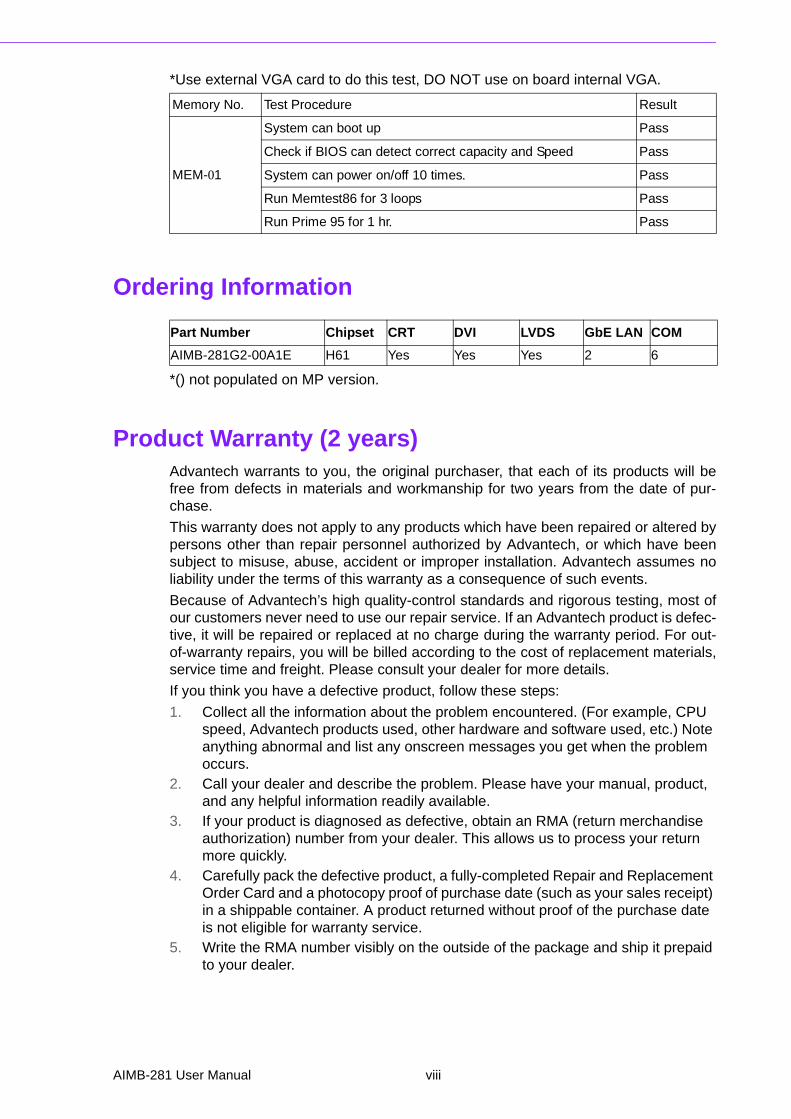
*Use external VGA card to do this test, DO NOT use on board internal VGA.
Ordering Information
*() not populated on MP version.
Product Warranty (2 years)Advantech warrants to you, the original purchaser, that each of its products will befree from defects in materials and workmanship for two years from the date of pur-chase.
This warranty does not apply to any products which have been repaired or altered bypersons other than repair personnel authorized by Advantech, or which have beensubject to misuse, abuse, accident or improper installation. Advantech assumes noliability under the terms of this warranty as a consequence of such events.
Because of Advantech’s high quality-control standards and rigorous testing, most ofour customers never need to use our repair service. If an Advantech product is defec-tive, it will be repaired or replaced at no charge during the warranty period. For out-of-warranty repairs, you will be billed according to the cost of replacement materials,service time and freight. Please consult your dealer for more details.
If you think you have a defective product, follow these steps:
1. Collect all the information about the problem encountered. (For example, CPU speed, Advantech products used, other hardware and software used, etc.) Note anything abnormal and list any onscreen messages you get when the problem occurs.
2. Call your dealer and describe the problem. Please have your manual, product, and any helpful information readily available.
3. If your product is diagnosed as defective, obtain an RMA (return merchandise authorization) number from your dealer. This allows us to process your return more quickly.
4. Carefully pack the defective product, a fully-completed Repair and Replacement Order Card and a photocopy proof of purchase date (such as your sales receipt) in a shippable container. A product returned without proof of the purchase date is not eligible for warranty service.
5. Write the RMA number visibly on the outside of the package and ship it prepaid to your dealer.
Memory No. Test Procedure Result
MEM-01
System can boot up Pass
Check if BIOS can detect correct capacity and Speed Pass
System can power on/off 10 times. Pass
Run Memtest86 for 3 loops Pass
Run Prime 95 for 1 hr. Pass
Part Number Chipset CRT DVI LVDS GbE LAN COM
AIMB-281G2-00A1E H61 Yes Yes Yes 2 6
AIMB-281 User Manual viii

Initial InspectionBefore you begin installing your motherboard, please make sure that the followingmaterials have been shipped:
1 x AIMB-281 Mini-ITX Motherboard 1 x Driver CD 2 x COM cable (2 x 10 pin) 2 x SATA cable (2 in 1,7-pin) 1 x I/O shield 1 x Startup manual 1 x Warranty card
If any of these items are missing or damaged, contact your distributor or sales repre-sentative immediately. We have carefully inspected the AIMB-281 mechanically andelectrically before shipment. It should be free of marks and scratches and in perfectworking order upon receipt. As you unpack the AIMB-281, check it for signs of ship-ping damage. (For example, damaged box, scratches, dents, etc.) If it is damaged orit fails to meet the specifications, notify our service department or your local salesrepresentative immediately. Also notify the carrier. Retain the shipping carton andpacking material for inspection by the carrier. After inspection, we will make arrange-ments to repair or replace the unit.
ix AIMB-281 User Manual

AIMB-281 User Manual x
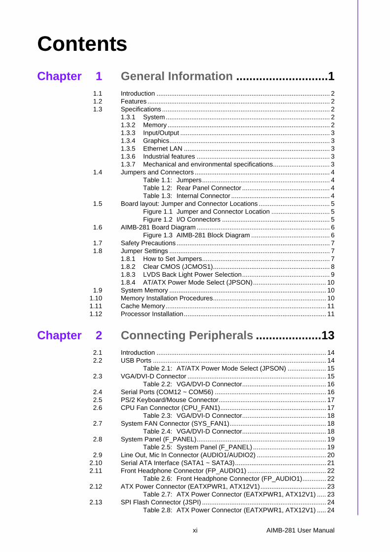
Contents
Chapter 1 General Information ............................11.1 Introduction ............................................................................................... 21.2 Features .................................................................................................... 21.3 Specifications ............................................................................................ 2
1.3.1 System.......................................................................................... 21.3.2 Memory ......................................................................................... 21.3.3 Input/Output .................................................................................. 31.3.4 Graphics........................................................................................ 31.3.5 Ethernet LAN ................................................................................ 31.3.6 Industrial features ......................................................................... 31.3.7 Mechanical and environmental specifications............................... 3
1.4 Jumpers and Connectors .......................................................................... 4Table 1.1: Jumpers...................................................................... 4Table 1.2: Rear Panel Connector ................................................ 4Table 1.3: Internal Connector ...................................................... 4
1.5 Board layout: Jumper and Connector Locations ....................................... 5Figure 1.1 Jumper and Connector Location ................................ 5Figure 1.2 I/O Connectors ........................................................... 5
1.6 AIMB-281 Board Diagram ......................................................................... 6Figure 1.3 AIMB-281 Block Diagram ........................................... 6
1.7 Safety Precautions .................................................................................... 71.8 Jumper Settings ........................................................................................ 7
1.8.1 How to Set Jumpers...................................................................... 71.8.2 Clear CMOS (JCMOS1)................................................................ 81.8.3 LVDS Back Light Power Selection................................................ 91.8.4 AT/ATX Power Mode Select (JPSON)........................................ 10
1.9 System Memory ...................................................................................... 101.10 Memory Installation Procedures.............................................................. 101.11 Cache Memory........................................................................................ 111.12 Processor Installation.............................................................................. 11
Chapter 2 Connecting Peripherals ....................132.1 Introduction ............................................................................................. 142.2 USB Ports ............................................................................................... 14
Table 2.1: AT/ATX Power Mode Select (JPSON) ..................... 152.3 VGA/DVI-D Connector ............................................................................ 15
Table 2.2: VGA/DVI-D Connector.............................................. 162.4 Serial Ports (COM12 ~ COM56) ............................................................. 162.5 PS/2 Keyboard/Mouse Connector........................................................... 172.6 CPU Fan Connector (CPU_FAN1).......................................................... 17
Table 2.3: VGA/DVI-D Connector.............................................. 182.7 System FAN Connector (SYS_FAN1)..................................................... 18
Table 2.4: VGA/DVI-D Connector.............................................. 182.8 System Panel (F_PANEL)....................................................................... 19
Table 2.5: System Panel (F_PANEL) ........................................ 192.9 Line Out, Mic In Connector (AUDIO1/AUDIO2) ...................................... 20
2.10 Serial ATA Interface (SATA1 ~ SATA3).................................................. 212.11 Front Headphone Connector (FP_AUDIO1) ........................................... 22
Table 2.6: Front Headphone Connector (FP_AUDIO1)............. 222.12 ATX Power Connector (EATXPWR1, ATX12V1).................................... 23
Table 2.7: ATX Power Connector (EATXPWR1, ATX12V1) ..... 232.13 SPI Flash Connector (JSPI) .................................................................... 24
Table 2.8: ATX Power Connector (EATXPWR1, ATX12V1) ..... 24
xi AIMB-281 User Manual
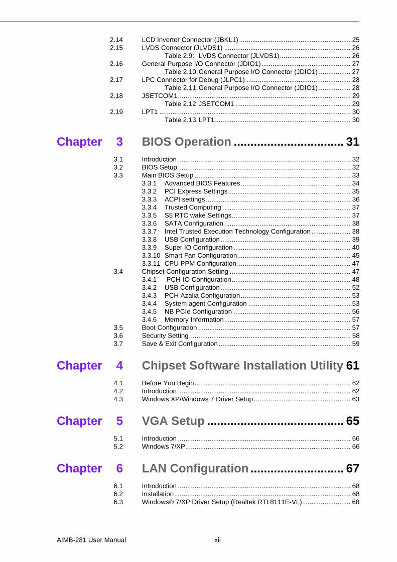
2.14 LCD Inverter Connector (JBKL1) ............................................................ 252.15 LVDS Connector (JLVDS1) .................................................................... 26
Table 2.9: LVDS Connector (JLVDS1)...................................... 262.16 General Purpose I/O Connector (JDIO1)................................................ 27
Table 2.10:General Purpose I/O Connector (JDIO1) ................. 272.17 LPC Connector for Debug (JLPC1) ........................................................ 28
Table 2.11:General Purpose I/O Connector (JDIO1) ................. 282.18 JSETCOM1............................................................................................. 29
Table 2.12:JSETCOM1 .............................................................. 292.19 LPT1 ....................................................................................................... 30
Table 2.13:LPT1......................................................................... 30
Chapter 3 BIOS Operation ................................. 313.1 Introduction ............................................................................................. 323.2 BIOS Setup ............................................................................................. 323.3 Main BIOS Setup .................................................................................... 33
3.3.1 Advanced BIOS Features ........................................................... 343.3.2 PCI Express Settings.................................................................. 353.3.3 ACPI settings .............................................................................. 363.3.4 Trusted Computing ..................................................................... 373.3.5 S5 RTC wake Settings................................................................ 373.3.6 SATA Configuration .................................................................... 383.3.7 Intel Trusted Execution Technology Configuration ..................... 383.3.8 USB Configuration ...................................................................... 393.3.9 Super IO Configuration ............................................................... 403.3.10 Smart Fan Configuration............................................................. 453.3.11 CPU PPM Configuration ............................................................. 47
3.4 Chipset Configuration Setting ................................................................. 473.4.1 PCH-IO Configuration................................................................ 483.4.2 USB Configuration ...................................................................... 523.4.3 PCH Azalia Configuration ........................................................... 533.4.4 System agent Configuration ....................................................... 533.4.5 NB PCIe Configuration ............................................................... 563.4.6 Memory Information.................................................................... 57
3.5 Boot Configuration .................................................................................. 573.6 Security Setting....................................................................................... 583.7 Save & Exit Configuration ....................................................................... 59
Chapter 4 Chipset Software Installation Utility 614.1 Before You Begin.................................................................................... 624.2 Introduction ............................................................................................. 624.3 Windows XP/Windows 7 Driver Setup .................................................... 63
Chapter 5 VGA Setup ......................................... 655.1 Introduction ............................................................................................. 665.2 Windows 7/XP......................................................................................... 66
Chapter 6 LAN Configuration ............................ 676.1 Introduction ............................................................................................. 686.2 Installation............................................................................................... 686.3 Windows® 7/XP Driver Setup (Realtek RTL8111E-VL).......................... 68
AIMB-281 User Manual xii

Appendix A Programming the Watchdog Timer..69A.1 Programming the Watchdog Timer ......................................................... 70
A.1.1 Watchdog Timer Overview.......................................................... 70A.1.2 Programming the Watchdog Timer ............................................. 70
Table A.1: Watchdog Timer Registers ....................................... 72A.1.3 Example Program ....................................................................... 73
xiii AIMB-281 User Manual

AIMB-281 User Manual xiv

Chapter 1
1 General Information
1.1 IntroductionAIMB-281 is designed with the Intel H61 for industrial applications that require bothperformance computing and enhanced power management capabilities. The mother-board supports Intel Core i7-3770 3.4 GHz/Core i5-3550S 3.0 GHz/Core i7-2600 3.4GHz/Core i5-3570 2.3 GHz/Core i5-3450 3.1 GHz/Core i5-2500T 2.3 GHz/Core i3-2125 3.3 GHz/Core i3-3220 3.3 GHz/Xeon E3-1275 3.4 GHz/Xeon E3-1225 3.1 GHz/Pentium G620 2.6 GHz/Celeron G460 1.8 GHz processor up to 8 MB L3 cache andDDR3 1066/1333/1600 up to 16 GB. It has rich I/O connectivity of 6 serial ports, 8USB 2.0, dual GbE LAN and 3 SATA II ports.
1.2 Features Rich I/O connectivity: Dual GbE LAN via PCIe x 1 bus, 8 USB 2.0 ports, 6
serial ports, 1 mini PCIe, and 1 PCIe x 4. Standard mini ATX form factor with industrial feature: The AIMB-281 is a full
featured mini ATX motherboard with balanced expandability and performance. Wide selection of storage devices: SATA HDD, customers benefit from the
flexibility of using the most suitable storage device for larger capacity. Optimized integrated graphic solution: With Intel® Flexible Display Interface,
it supports versatile display options and 32-bit 3D graphics engine.
1.3 Specifications
1.3.1 System CPU: Intel Core i7-3770 3.4 GHz/Core i5-3550S 3.0GHz/Core i7-2600 3.4GHz/
Core i5-3570 2.3 GHz/Core i5-3450 3.1 GHz/Core i5-2500T 2.3 GHz/Core i3-2125 3.3 GHz/Core i3-3220 3.3 GHz/Xeon E3-1275 3.4 GHz/Xeon E3-1225 3.1 GHz/Pentium G620 2.6 GHz/Celeron G460 1.8 GHz processor
BIOS: AMI EFI 32 Mbit SPI BIOS System chipset: Intel® H61 SATA hard disk drive interface: Three on-board SATA connectors with data
transmission rate up to 300 MB
1.3.2 Memory RAM: Up to 16 GB in 2 slots 204-pin DIMM sockets. Supports dual-channel
DDR3 1066/1333/1600f MHz SDRAM.– Supports non-ECC unbuffered DIMMs and do not support any memory con-
figuration that mixes non-ECC with ECC unbuffered DIMMs.
Note! A 32-bit OS may not fully detected 16 GB of RAM when 16 GB is installed.
AIMB-281 User Manual 2
Chapter 1
GeneralInform
ation
1.3.3 Input/Output PCIe slot: 1 mini-PCIe expansion slot and 1 PCIe x4 expansion slot. Parallel port: Configured to LPT1 or disabled. LPT1 supports EPP/SPP/ECP. Serial port: Six serial ports, two RS-232 with hardware auto-flow control and
four RS-232. PS/2 mouse connector: One connector is located on the mounting bracket for
easy connection to PS/2 keyboard and mouse. USB port: Supports up to 8 USB 2.0 ports with transmission rates up to 480
Mbps. GPIO: AIMB-281 supports 8-bit GPIO from super I/O for general purpose con-
trol application.
1.3.4 Graphics Controller: Intel® HD Graphics Display memory: 256 MB maximum shared memory with 2GB and above sys-
tem memory installed DVI: Supports DVI up to resolution 1920 x 1200 @ 60Hz refresh rate CRT: Supports VGA up to resolution 2048 x 1536 @ 75Hz refresh rate LVDS: Supports LVDS up to resolution 1920 x 1200
1.3.5 Ethernet LAN Supports dual 10/100/1000 Mbps Ethernet port (s) via PCI Express x1 bus
which provides 500 MB/s data transmission rate Controller: LAN 1: Realtek 8111E; LAN 2: Realtek 8111E
1.3.6 Industrial features Watchdog timer: Can generate a system reset. The watchdog timer is pro-
grammable, with each unit equal to one second or one minute (255 levels)
1.3.7 Mechanical and environmental specifications Operating temperature: 0 ~ 60° C (32 ~ 140° F, depending on CPU) Storage temperature: -20 ~ 70° C (-4 ~ 158° F) Humidity: 5 ~ 95% non-condensing Power supply voltage: +3.3 V, +5 V, +12 V, -12 V, 5 Vsb Power consumption:
- Intel LGA1155 Core i7-2600 3.4 GHz, 8MB L3 cache, 2pcs 4GB DDR3 1600MHz, +5V @1.38A, +3.3V @ 1.2A, +12V @ 7.25A, 5Vsb @ 0.15A, -12V @0.24A
Measure the maximum current value which system under maximum load (CPU:Top speed, RAM: Full loading)
Board size: 170 mm x 170 mm (6.69" x 6.69") Board weight: 1.04 kg
3 AIMB-281 User Manual

1.4 Jumpers and ConnectorsConnectors on the AIMB-281 motherboard link it to devices such as hard disk drivesand a keyboard. In addition, the board has a number of jumpers used to configureyour system for your application.
The tables below list the function of each of the board jumpers and connectors. Latersections in this chapter give instructions on setting jumpers. Chapter 2 gives instruc-tions for connecting external devices to your motherboard.
Table 1.1: Jumpers
Label Function Note
JCMOS1 Clear CMOS 3 x 1 header, pitch 2.0mm
JPSON AT/ATX Mode Select 3 x 1 header, pitch 2.0mm
JLVDS_BKL1 BL Selec 3 x 1 header, pitch 2.0mm
SelectCOM SelectCOM 9 x 2 header, pitch 2.0mm
SPI1 4 x 2 header, pitch 2.54mm
JLPC 6 x 2 header, pitch 2.0mm
LPT 13 x 2 header, pitch 2.54mm
Table 1.2: Rear Panel ConnectorLabel Function Note
KBMS_USB PS/2 KB/Mouse/2 USB 2.0 6-pin Mini-Din
DVI DVI Port 29-pin DVI-D port
VGA1 VGA Port D-sub 15-pin, female
LAN1USB12RJ-45 Ethernet Connector x 1USB 2.0 Connector x 2
LAN2USB34RJ-45 Ethernet Connector x 1USB 2.0 Connector x 2
Audio1 Audio , Line-Out , Mic.-In
Table 1.3: Internal Connector
Label Function Note
CPU_FAN CPU Fan Connector 4 x 1 wafer, pitch 2.54mm
SYS_FAN1 System Fan Connector 3 x 1 wafer, pitch 2.54mm
COM3~6 Pin Header Connector * 2 10X2 header, pitch 2.0mm
JDIO GPIO Connector 5 x 2 header, pitch 2.0mm
F_PANEL1 Intel Front Panel Connector 5 x 2 header, pitch 2.54mm
EATXPWR EATX power Connectors 12 x 2 header
FPAUD1 Audio Mic.-In & Line-Out Connector 5 x 2 header, pitch 2.54mm
JLVDS 24-bit LVDS Connector 2 x 20 connector
JBKL LCD Inverter Connector 1 x 5 connector
SATA1 ~ 3 SATA Data Connector * 3 7P Male connector
ATX12V ATX Power Connector 2x2 pin power connector
USB78 USB Connector * 1 5 x 2 header, pitch 2.0mm
AIMB-281 User Manual 4
Chapter 1
GeneralInform
ation
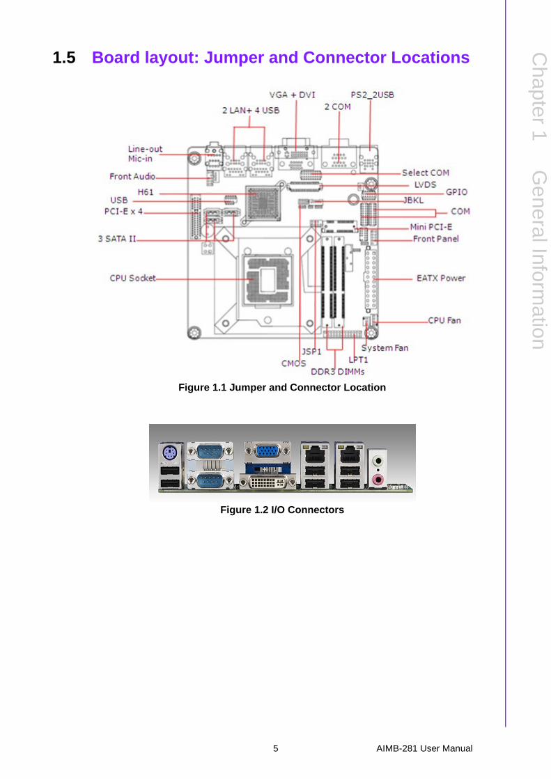
1.5 Board layout: Jumper and Connector Locations
Figure 1.1 Jumper and Connector Location
Figure 1.2 I/O Connectors
5 AIMB-281 User Manual
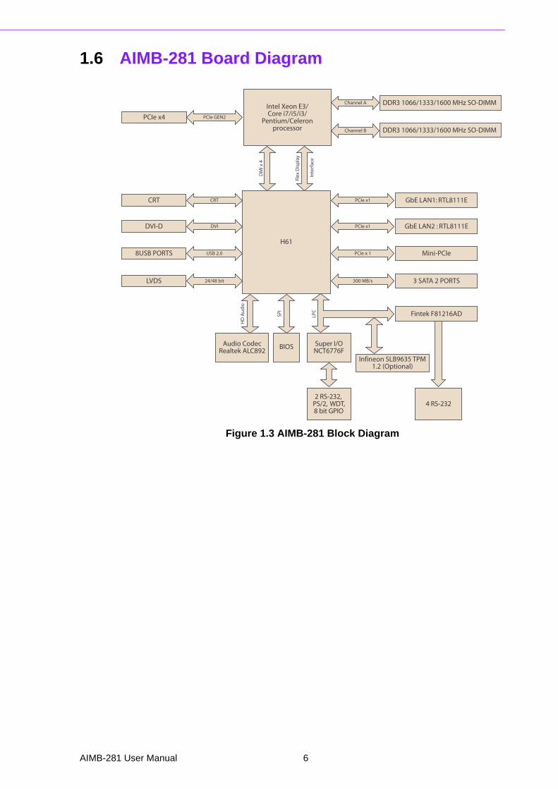
1.6 AIMB-281 Board Diagram
Figure 1.3 AIMB-281 Block Diagram
Intel Xeon E3/Core i7/i5/i3/
Pentium/Celeronprocessor
BIOS
Infineon SLB9635 TPM1.2 (Optional)
Audio CodecRealtek ALC892
Super I/ONCT6776F
2 RS-232, PS/2, WDT,8 bit GPIO
4 RS-232
Flex
Dis
pla
y
Inte
rfac
e
DM
I x 4
H61
PCIe GEN2
DDR3 1066/1333/1600 MHz SO-DIMM
DDR3 1066/1333/1600 MHz SO-DIMM
Channel A
Channel B
GbE LAN1: RTL8111E
Mini-PCIe
PCIe x4
LPC
HD
Au
dio
SPI
CRT
DVI-D
8USB PORTS
DVI
CRT PCIe x1
PCIe x 1
3 SATA 2 PORTS300 MB/s
GbE LAN2 : RTL8111EPCIe x1
Fintek F81216AD
USB 2.0
LVDS 24/48 bit
AIMB-281 User Manual 6

Chapter 1
GeneralInform
ation
1.7 Safety Precautions
1.8 Jumper SettingsThis section provides instructions on how to configure your motherboard by settingthe jumpers. It also includes the motherboards's default settings and your options foreach jumper.
1.8.1 How to Set JumpersYou can configure your motherboard to match the needs of your application by set-ting the jumpers. A jumper is a metal bridge that closes an electrical circuit. It consistsof two metal pins and a small metal clip (often protected by a plastic cover) that slidesover the pins to connect them. To “close” (or turn ON) a jumper, you connect the pinswith the clip. To “open” (or turn OFF) a jumper, you remove the clip. Sometimes ajumper consists of a set of three pins, labeled 1, 2, and 3. In this case you connecteither pins 1 and 2, or 2 and 3. A pair of needle-nose pliers may be useful when set-ting jumpers.
Warning! Always completely disconnect the power cord from chassis whenever you work with the hardware. Do not make connections while the power is on. Sensitive electronic components can be damaged by sudden power surges. Only experienced electronics personnel should open the PC chassis.
Caution! Always ground yourself to remove any static charge before touching the motherboard. Modern electronic devices are very sensitive to electro-static discharges. As a safety precaution, use a grounding wrist strap at all times. Place all electronic components on a static-dissipative surface or in a static-shielded bag when they are not in the chassis.
Caution! The computer is provided with a battery-powered real-time clock circuit. There is a danger of explosion if battery is incorrectly replaced. Replace only with same or equivalent type recommended by the manufacturer. Discard used batteries according to manufacturer's instructions.
Caution! There is a danger of a new battery exploding if it is incorrectly installed. Do not attempt to recharge, force open, or heat the battery. Replace the battery only with the same or equivalent type recommended by the man-ufacturer. Discard used batteries according to the manufacturer’s instructions.
7 AIMB-281 User Manual
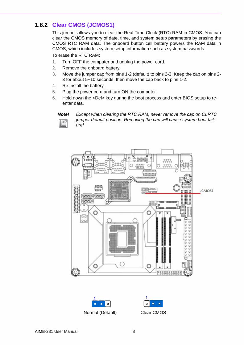
1.8.2 Clear CMOS (JCMOS1) This jumper allows you to clear the Real Time Clock (RTC) RAM in CMOS. You canclear the CMOS memory of date, time, and system setup parameters by erasing theCMOS RTC RAM data. The onboard button cell battery powers the RAM data inCMOS, which includes system setup information such as system passwords.
To erase the RTC RAM:
1. Turn OFF the computer and unplug the power cord.2. Remove the onboard battery.3. Move the jumper cap from pins 1-2 (default) to pins 2-3. Keep the cap on pins 2-
3 for about 5~10 seconds, then move the cap back to pins 1-2.4. Re-install the battery.5. Plug the power cord and turn ON the computer.6. Hold down the <Del> key during the boot process and enter BIOS setup to re-
enter data.
Normal (Default) Clear CMOS
Note! Except when clearing the RTC RAM, never remove the cap on CLRTC jumper default position. Removing the cap will cause system boot fail-ure!
AIMB-281 User Manual 8
Chapter 1
GeneralInform
ation
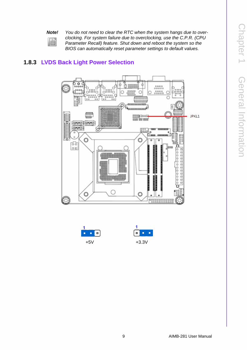
1.8.3 LVDS Back Light Power Selection
+5V +3.3V
Note! You do not need to clear the RTC when the system hangs due to over-clocking. For system failure due to overclocking, use the C.P.R. (CPU Parameter Recall) feature. Shut down and reboot the system so the BIOS can automatically reset parameter settings to default values.
9 AIMB-281 User Manual
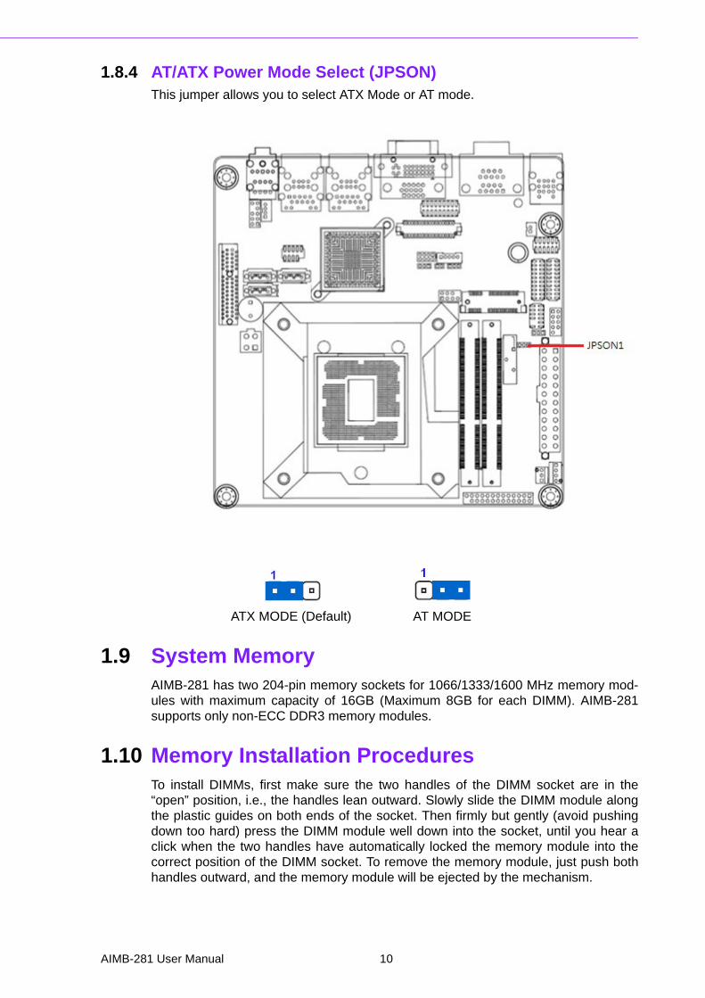
1.8.4 AT/ATX Power Mode Select (JPSON)This jumper allows you to select ATX Mode or AT mode.
ATX MODE (Default) AT MODE
1.9 System MemoryAIMB-281 has two 204-pin memory sockets for 1066/1333/1600 MHz memory mod-ules with maximum capacity of 16GB (Maximum 8GB for each DIMM). AIMB-281supports only non-ECC DDR3 memory modules.
1.10 Memory Installation ProceduresTo install DIMMs, first make sure the two handles of the DIMM socket are in the“open” position, i.e., the handles lean outward. Slowly slide the DIMM module alongthe plastic guides on both ends of the socket. Then firmly but gently (avoid pushingdown too hard) press the DIMM module well down into the socket, until you hear aclick when the two handles have automatically locked the memory module into thecorrect position of the DIMM socket. To remove the memory module, just push bothhandles outward, and the memory module will be ejected by the mechanism.
AIMB-281 User Manual 10
Chapter 1
GeneralInform
ation
1.11 Cache MemoryThe AIMB-281 supports a CPU with one of the following built-in full speed L3 caches:
8 MB for Intel Core i7-3770
6 MB for Intel Core i5-3550
3 MB for Intel Core i3-3220
8 MB for Intel Core i7-2600
6 MB for Intel Core i5-3570
3 MB for Intel Core i3-2125
6 MB for Intel Core i5-3450
6 MB for Intel Core i5-2500
8 MB for Intel Xeon E3-1275
6 MB for Intel Xeon E3-1225
3 MB for Intel Pentium G620
1.5 MB for Intel Celeron G460
The built-in second-level cache in the processor yields much higher performancethan conventional external cache memories.
1.12 Processor InstallationThe AIMB-281 is designed for LGA1155, Intel Core i7/Core i5/Core i3/Pentium/Cel-eron processor.
11 AIMB-281 User Manual

AIMB-281 User Manual 12

Chapter 2
2 Connecting Peripherals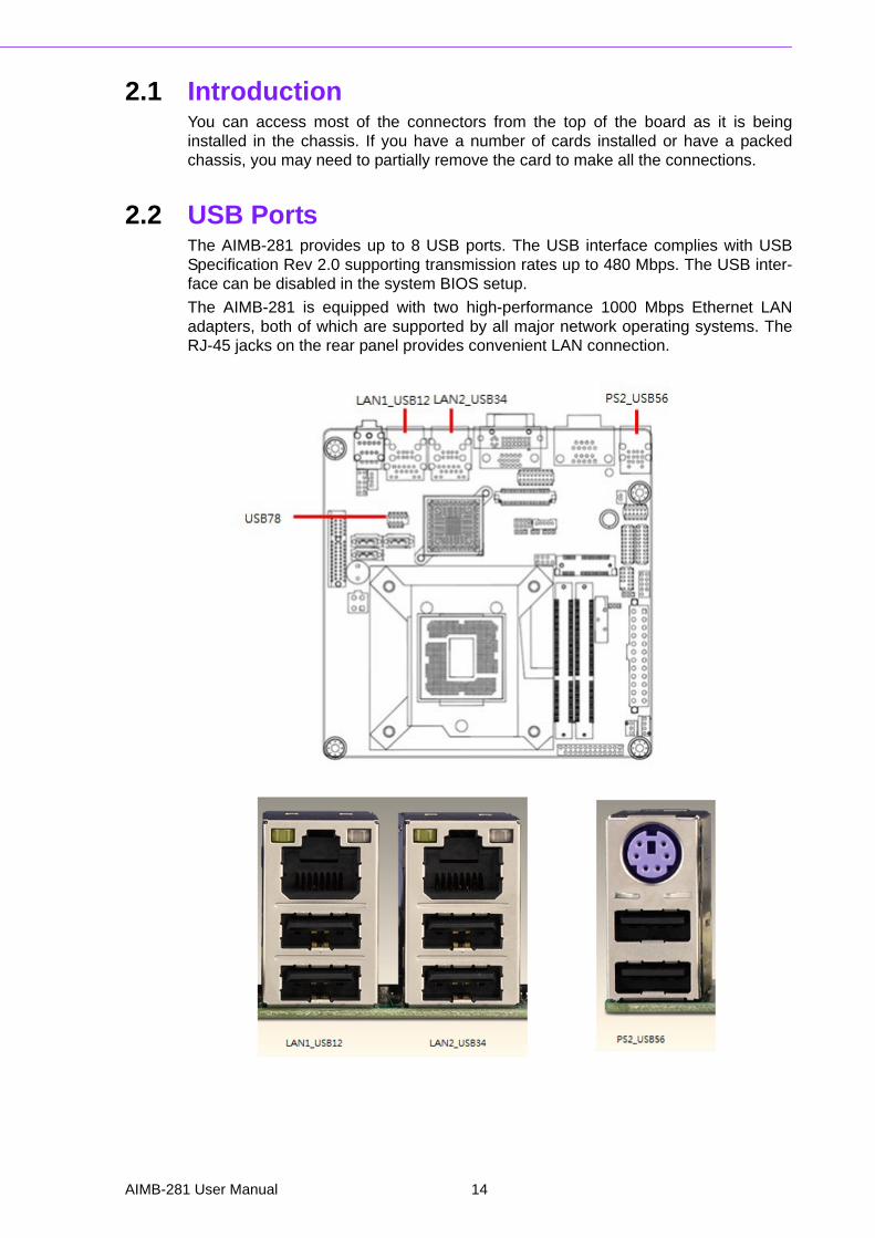
2.1 IntroductionYou can access most of the connectors from the top of the board as it is beinginstalled in the chassis. If you have a number of cards installed or have a packedchassis, you may need to partially remove the card to make all the connections.
2.2 USB PortsThe AIMB-281 provides up to 8 USB ports. The USB interface complies with USBSpecification Rev 2.0 supporting transmission rates up to 480 Mbps. The USB inter-face can be disabled in the system BIOS setup.
The AIMB-281 is equipped with two high-performance 1000 Mbps Ethernet LANadapters, both of which are supported by all major network operating systems. TheRJ-45 jacks on the rear panel provides convenient LAN connection.
AIMB-281 User Manual 14
Chapter 2
Connecting
Peripherals
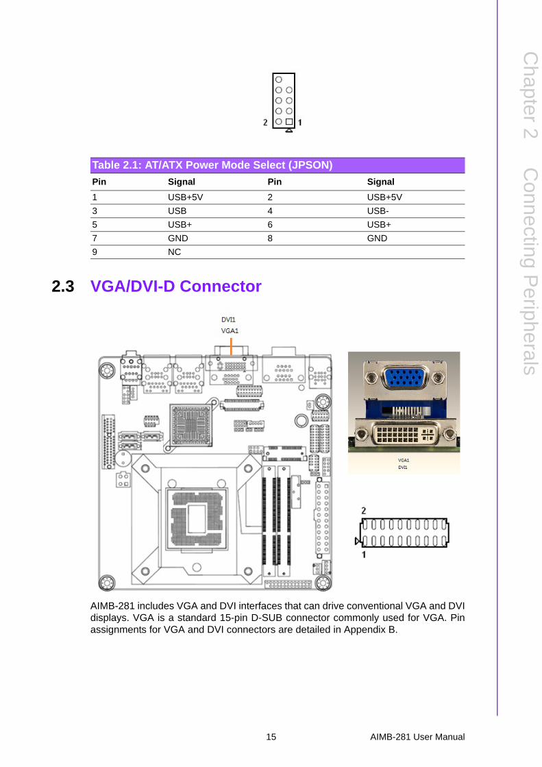
2.3 VGA/DVI-D Connector
AIMB-281 includes VGA and DVI interfaces that can drive conventional VGA and DVIdisplays. VGA is a standard 15-pin D-SUB connector commonly used for VGA. Pinassignments for VGA and DVI connectors are detailed in Appendix B.
Table 2.1: AT/ATX Power Mode Select (JPSON)
Pin Signal Pin Signal
1 USB+5V 2 USB+5V
3 USB 4 USB-
5 USB+ 6 USB+
7 GND 8 GND
9 NC
15 AIMB-281 User Manual

2.4 Serial Ports (COM12 ~ COM56)
AIMB-281 supports six serial ports. COM34. COM56 supports RS-232. COM12 sup-ports RS-232/422/485 (supports RS-485 auto flow control). JSETCOM3 &
These ports can connect to serial devices, such as a mouse or a printer, or to a com-munications network.
The IRQ and address ranges for both ports are fixed. However, if you want to disablethe port or change these parameters later, you can do this in the system BIOS setup.
Different devices implement the RS-232 standards in different ways. If you haveproblems with a serial device, be sure to check the pin assignments for the connec-tor.
Table 2.2: VGA/DVI-D Connector
Pin Signal Pin Signal
1 DCD# 2 DSR#
3 RXD 4 RTS#
5 TXD 6 CTS#
7 DTR# 8 RI#
9 GND 10 GND
11 DCD# 12 DSR#
13 RXD 14 RTS#
15 TXD 16 CTS#
17 DTR# 18 RI#
19 GND 20 GND
AIMB-281 User Manual 16
Chapter 2
Connecting
Peripherals
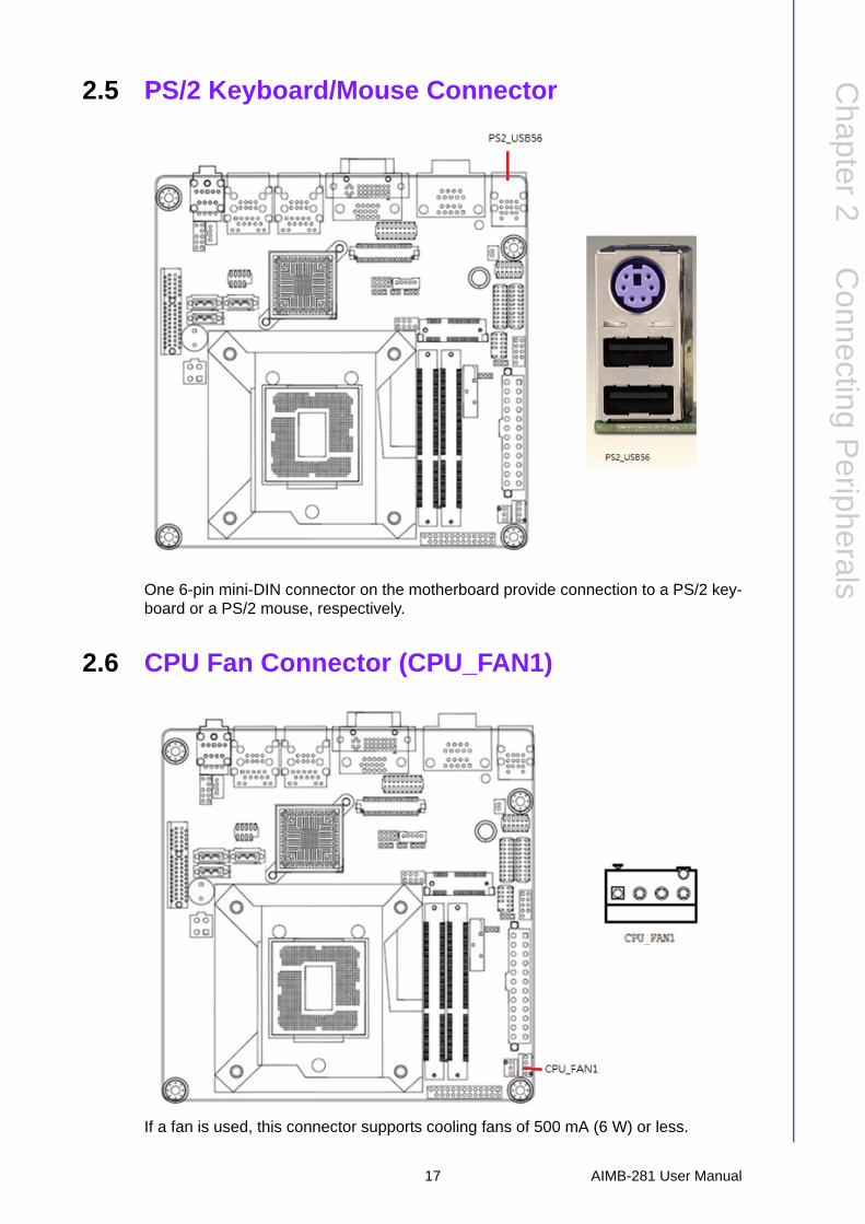
2.5 PS/2 Keyboard/Mouse Connector
One 6-pin mini-DIN connector on the motherboard provide connection to a PS/2 key-board or a PS/2 mouse, respectively.
2.6 CPU Fan Connector (CPU_FAN1)
If a fan is used, this connector supports cooling fans of 500 mA (6 W) or less.
17 AIMB-281 User Manual
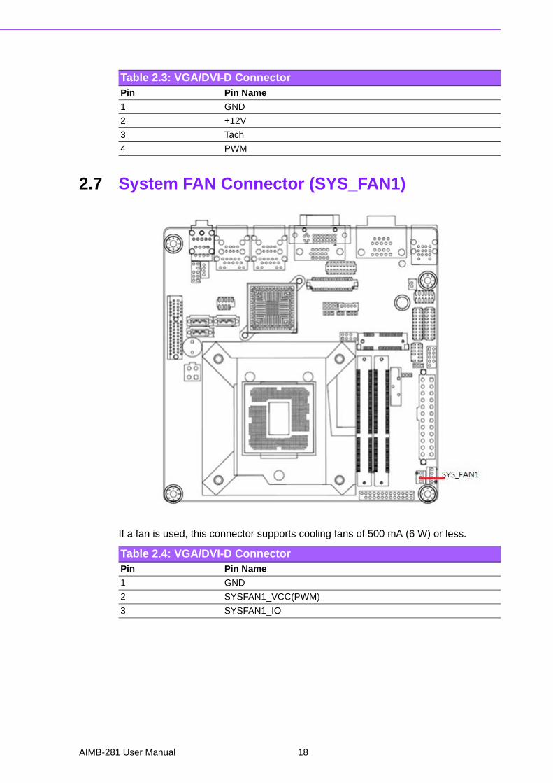
2.7 System FAN Connector (SYS_FAN1)
If a fan is used, this connector supports cooling fans of 500 mA (6 W) or less.
Table 2.3: VGA/DVI-D ConnectorPin Pin Name
1 GND
2 +12V
3 Tach
4 PWM
Table 2.4: VGA/DVI-D ConnectorPin Pin Name
1 GND
2 SYSFAN1_VCC(PWM)
3 SYSFAN1_IO
AIMB-281 User Manual 18
Chapter 2
Connecting
Peripherals
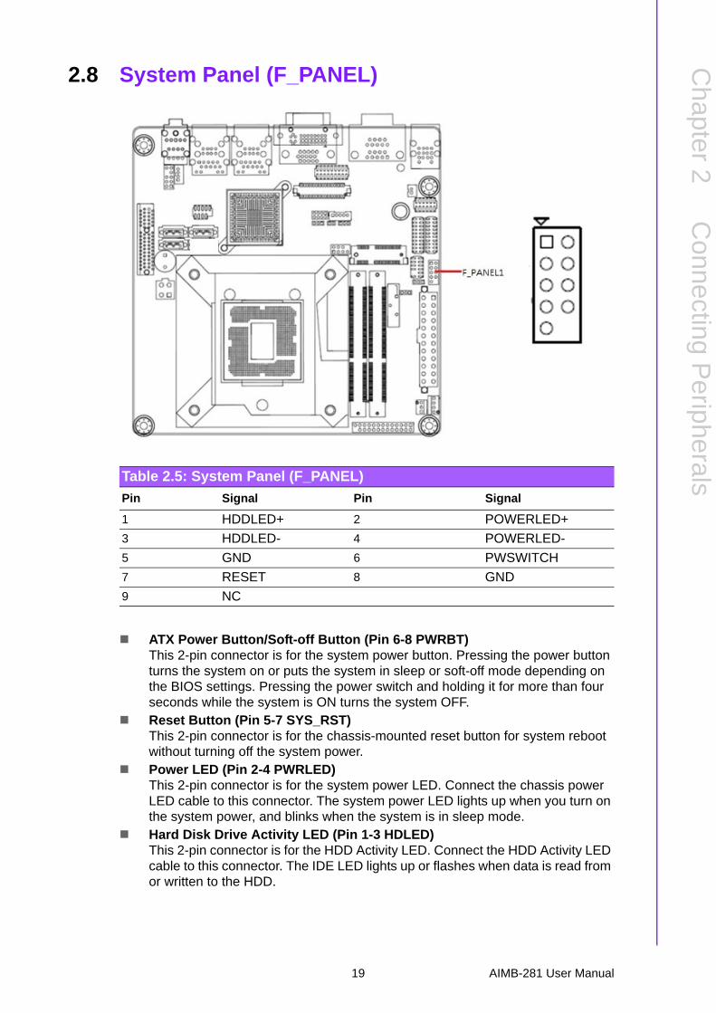
2.8 System Panel (F_PANEL)
ATX Power Button/Soft-off Button (Pin 6-8 PWRBT)This 2-pin connector is for the system power button. Pressing the power button turns the system on or puts the system in sleep or soft-off mode depending on the BIOS settings. Pressing the power switch and holding it for more than four seconds while the system is ON turns the system OFF.
Reset Button (Pin 5-7 SYS_RST)This 2-pin connector is for the chassis-mounted reset button for system reboot without turning off the system power.
Power LED (Pin 2-4 PWRLED)This 2-pin connector is for the system power LED. Connect the chassis power LED cable to this connector. The system power LED lights up when you turn on the system power, and blinks when the system is in sleep mode.
Hard Disk Drive Activity LED (Pin 1-3 HDLED)This 2-pin connector is for the HDD Activity LED. Connect the HDD Activity LED cable to this connector. The IDE LED lights up or flashes when data is read from or written to the HDD.
Table 2.5: System Panel (F_PANEL)
Pin Signal Pin Signal
1 HDDLED+ 2 POWERLED+
3 HDDLED- 4 POWERLED-
5 GND 6 PWSWITCH
7 RESET 8 GND
9 NC
19 AIMB-281 User Manual
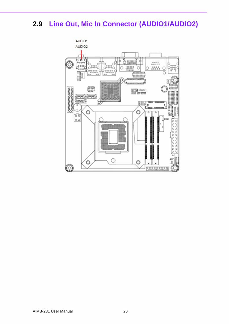
2.9 Line Out, Mic In Connector (AUDIO1/AUDIO2)
AIMB-281 User Manual 20
Chapter 2
Connecting
Peripherals
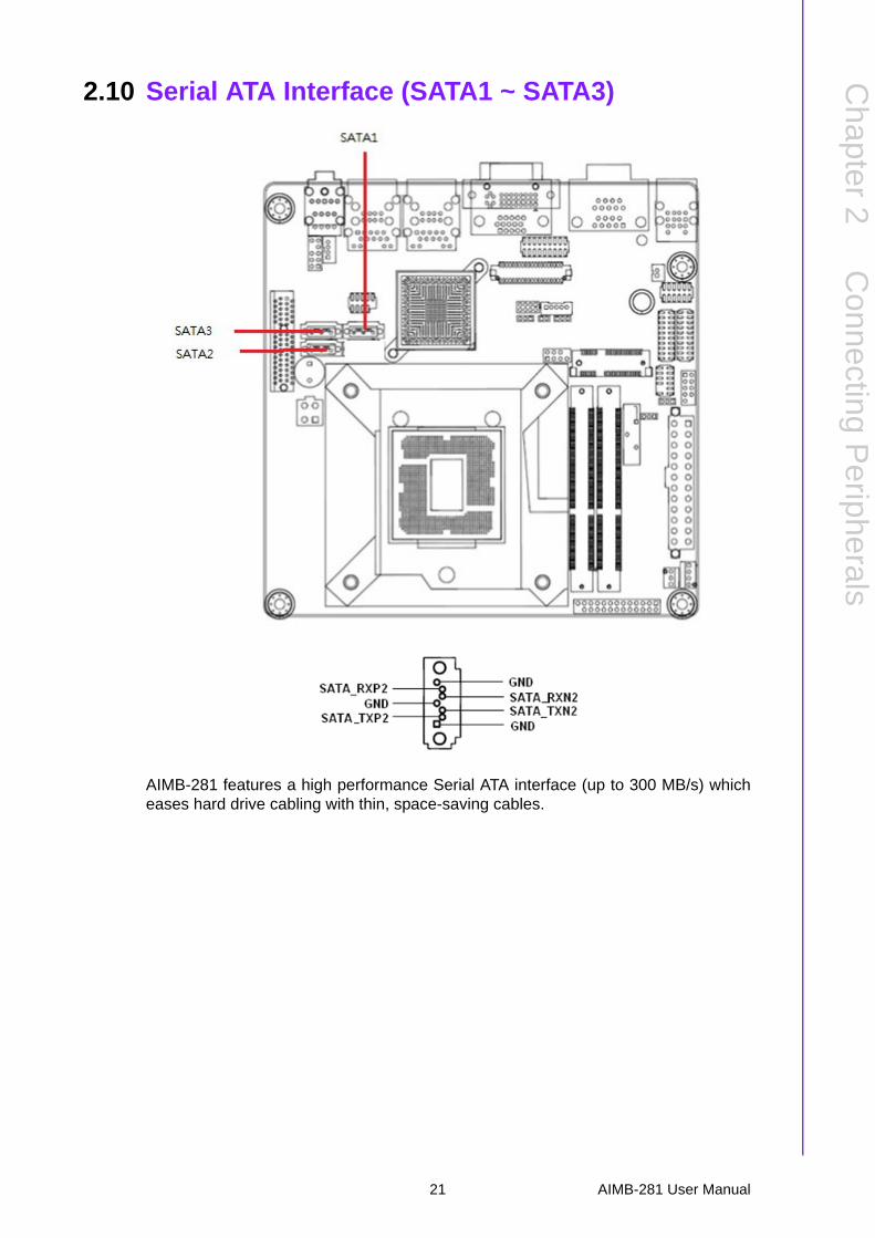
2.10 Serial ATA Interface (SATA1 ~ SATA3)
AIMB-281 features a high performance Serial ATA interface (up to 300 MB/s) whicheases hard drive cabling with thin, space-saving cables.
21 AIMB-281 User Manual
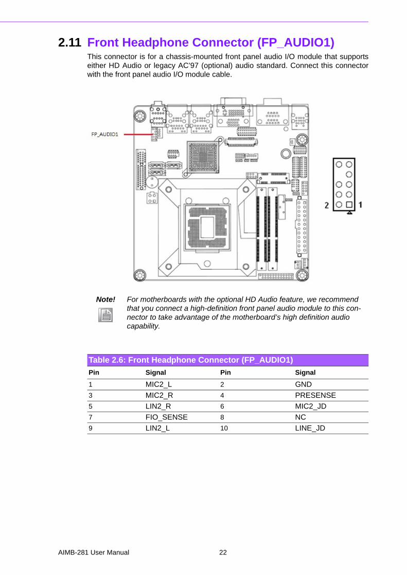
2.11 Front Headphone Connector (FP_AUDIO1)This connector is for a chassis-mounted front panel audio I/O module that supportseither HD Audio or legacy AC’97 (optional) audio standard. Connect this connectorwith the front panel audio I/O module cable.
Note! For motherboards with the optional HD Audio feature, we recommend that you connect a high-definition front panel audio module to this con-nector to take advantage of the motherboard’s high definition audio capability.
Table 2.6: Front Headphone Connector (FP_AUDIO1)
Pin Signal Pin Signal
1 MIC2_L 2 GND
3 MIC2_R 4 PRESENSE
5 LIN2_R 6 MIC2_JD
7 FIO_SENSE 8 NC
9 LIN2_L 10 LINE_JD
AIMB-281 User Manual 22
Chapter 2
Connecting
Peripherals
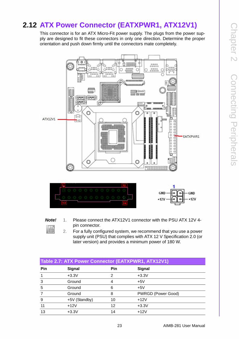
2.12 ATX Power Connector (EATXPWR1, ATX12V1)This connector is for an ATX Micro-Fit power supply. The plugs from the power sup-ply are designed to fit these connectors in only one direction. Determine the properorientation and push down firmly until the connectors mate completely.
Note! 1. Please connect the ATX12V1 connector with the PSU ATX 12V 4-pin connector.
2. For a fully configured system, we recommend that you use a power supply unit (PSU) that complies with ATX 12 V Specification 2.0 (or later version) and provides a minimum power of 180 W.
Table 2.7: ATX Power Connector (EATXPWR1, ATX12V1)
Pin Signal Pin Signal
1 +3.3V 2 +3.3V
3 Ground 4 +5V
5 Ground 6 +5V
7 Ground 8 PWRGD (Power Good)
9 +5V (Standby) 10 +12V
11 +12V 12 +3.3V
13 +3.3V 14 +12V
23 AIMB-281 User Manual
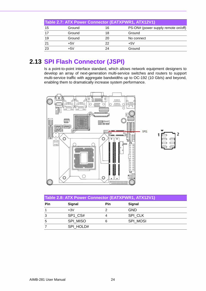
2.13 SPI Flash Connector (JSPI)Is a point-to-point interface standard, which allows network equipment designers todevelop an array of next-generation multi-service switches and routers to supportmulti-service traffic with aggregate bandwidths up to OC-192 (10 Gb/s) and beyond,enabling them to dramatically increase system performance.
15 Ground 16 PS-ON# (power supply remote on/off)
17 Ground 18 Ground
19 Ground 20 No connect
21 +5V 22 +5V
23 +5V 24 Ground
Table 2.7: ATX Power Connector (EATXPWR1, ATX12V1)
Table 2.8: ATX Power Connector (EATXPWR1, ATX12V1)
Pin Signal Pin Signal
1 +3V 2 GND
3 SP1_CS# 4 SPI_CLK
5 SPI_MISO 6 SPI_MOSI
7 SPI_HOLD#
AIMB-281 User Manual 24
Chapter 2
Connecting
Peripherals
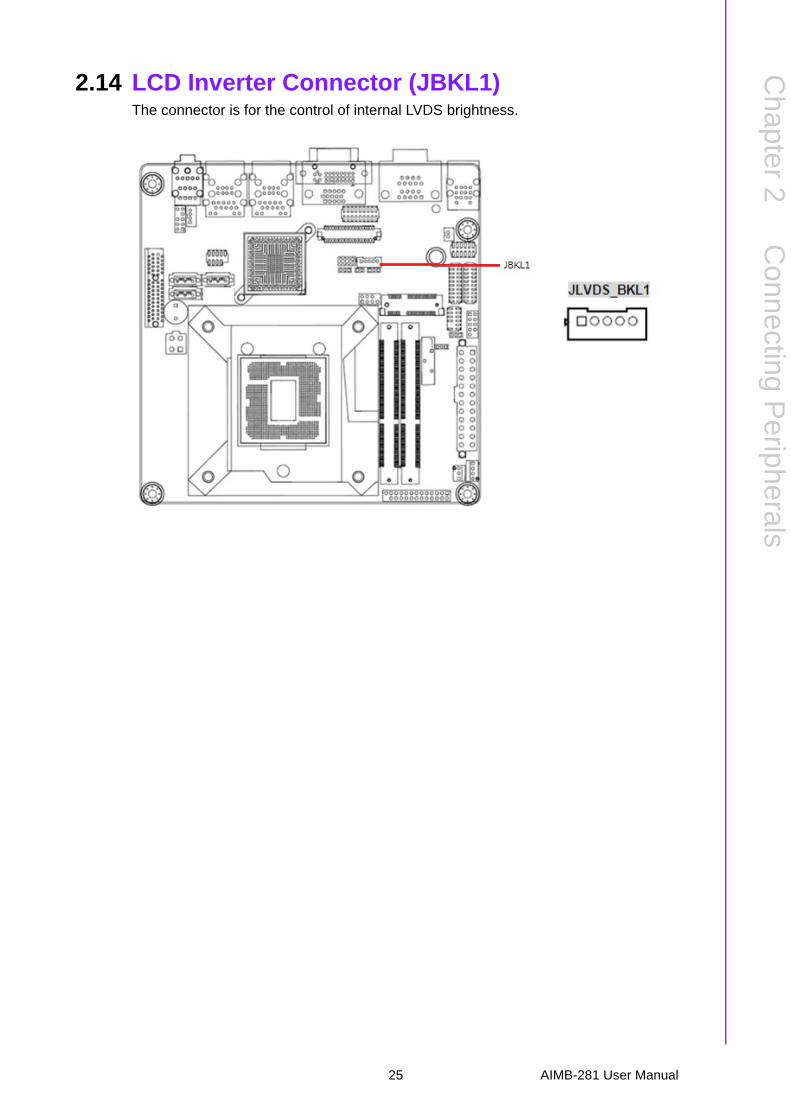
2.14 LCD Inverter Connector (JBKL1)The connector is for the control of internal LVDS brightness.
25 AIMB-281 User Manual

2.15 LVDS Connector (JLVDS1)
Table 2.9: LVDS Connector (JLVDS1)
Pin Signal Pin Signal
1 VDD(+3.3V) 2 VDD(+5V)
3 VDD(+3.3V) 4 VDD(+5V)
5 I2C_CLK 6 I2C_DATA
7 GND 8 GND
9 LVDS_A1+ 10 LVDS_A0+
11 LVDS_A1- 12 LVDS_A0-
13 GND 14 GND
15 LVDS_A3+ 16 LVDS_A2+
17 LVDS_A3- 18 LVDS_A2-
19 GND 20 GND
21 LVDS_B1+ 22 LVDS_B0+
23 LVDS_B1- 24 LVDS_B0-
25 GND 26 GND
27 LVDS_B3+ 28 LVDS_B2+
AIMB-281 User Manual 26
Chapter 2
Connecting
Peripherals
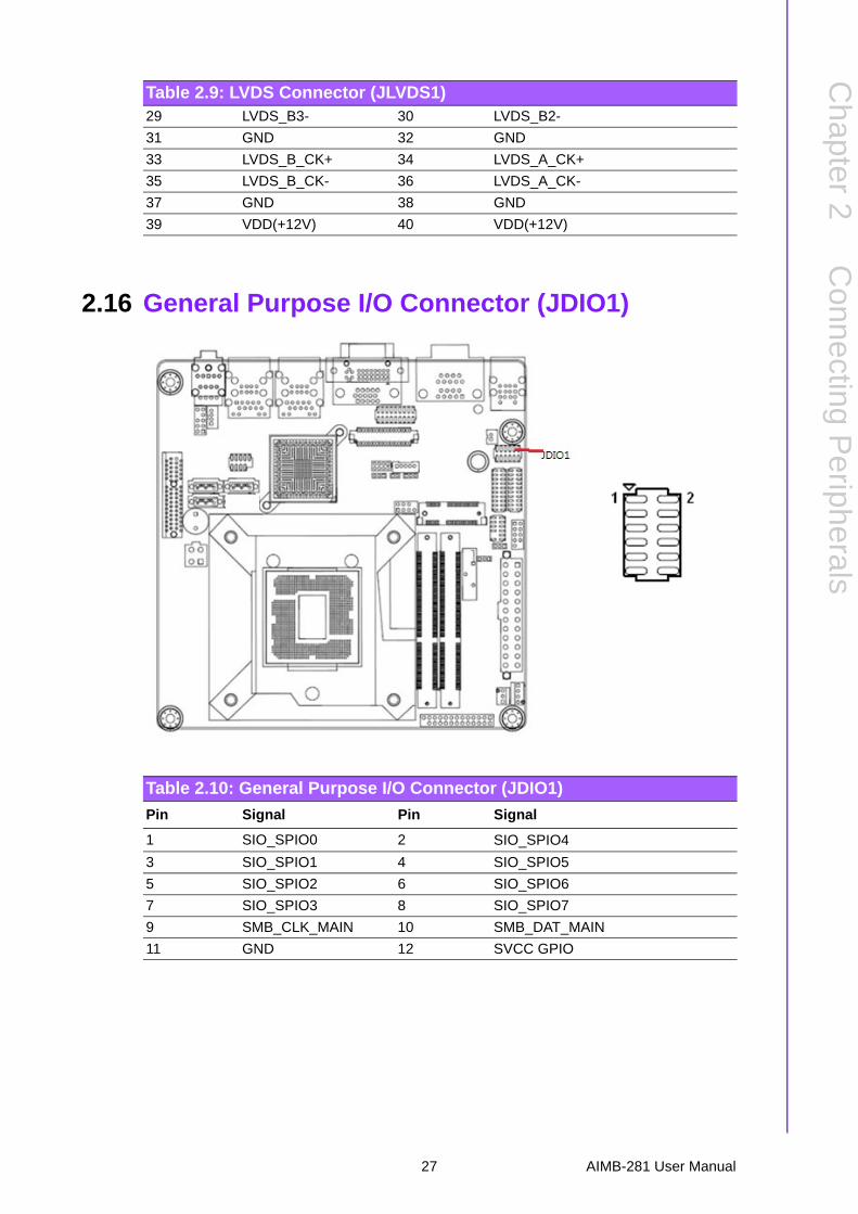
2.16 General Purpose I/O Connector (JDIO1)
29 LVDS_B3- 30 LVDS_B2-
31 GND 32 GND
33 LVDS_B_CK+ 34 LVDS_A_CK+
35 LVDS_B_CK- 36 LVDS_A_CK-
37 GND 38 GND
39 VDD(+12V) 40 VDD(+12V)
Table 2.9: LVDS Connector (JLVDS1)
Table 2.10: General Purpose I/O Connector (JDIO1)
Pin Signal Pin Signal
1 SIO_SPIO0 2 SIO_SPIO4
3 SIO_SPIO1 4 SIO_SPIO5
5 SIO_SPIO2 6 SIO_SPIO6
7 SIO_SPIO3 8 SIO_SPIO7
9 SMB_CLK_MAIN 10 SMB_DAT_MAIN
11 GND 12 SVCC GPIO
27 AIMB-281 User Manual
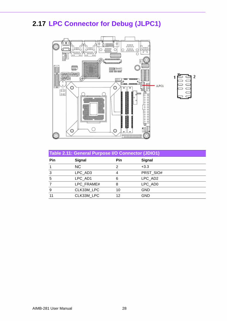
2.17 LPC Connector for Debug (JLPC1)
Table 2.11: General Purpose I/O Connector (JDIO1)
Pin Signal Pin Signal
1 NC 2 +3.3
3 LPC_AD3 4 PRST_SIO#
5 LPC_AD1 6 LPC_AD2
7 LPC_FRAME# 8 LPC_AD0
9 CLK33M_LPC 10 GND
11 CLK33M_LPC 12 GND
AIMB-281 User Manual 28
Chapter 2
Connecting
Peripherals
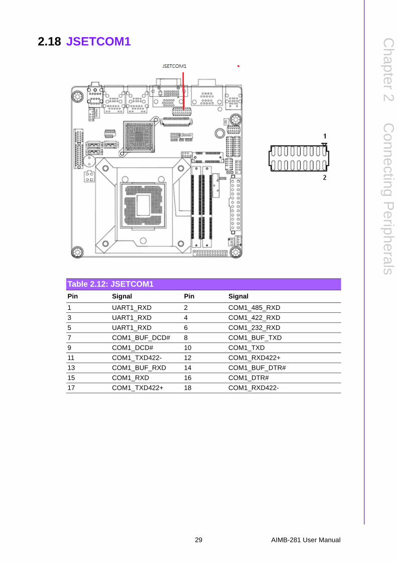
2.18 JSETCOM1
Table 2.12: JSETCOM1
Pin Signal Pin Signal
1 UART1_RXD 2 COM1_485_RXD
3 UART1_RXD 4 COM1_422_RXD
5 UART1_RXD 6 COM1_232_RXD
7 COM1_BUF_DCD# 8 COM1_BUF_TXD
9 COM1_DCD# 10 COM1_TXD
11 COM1_TXD422- 12 COM1_RXD422+
13 COM1_BUF_RXD 14 COM1_BUF_DTR#
15 COM1_RXD 16 COM1_DTR#
17 COM1_TXD422+ 18 COM1_RXD422-
29 AIMB-281 User Manual
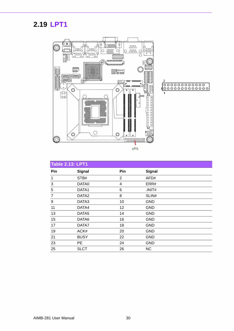
2.19 LPT1
Table 2.13: LPT1
Pin Signal Pin Signal
1 STB# 2 AFD#
3 DATA0 4 ERR#
5 DATA1 6 .INIT#
7 DATA2 8 SLIN#
9 DATA3 10 GND
11 DATA4 12 GND
13 DATA5 14 GND
15 DATA6 16 GND
17 DATA7 18 GND
19 ACK# 20 GND
21 BUSY 22 GND
23 PE 24 GND
25 SLCT 26 NC
AIMB-281 User Manual 30

Chapter 3
3 BIOS Operation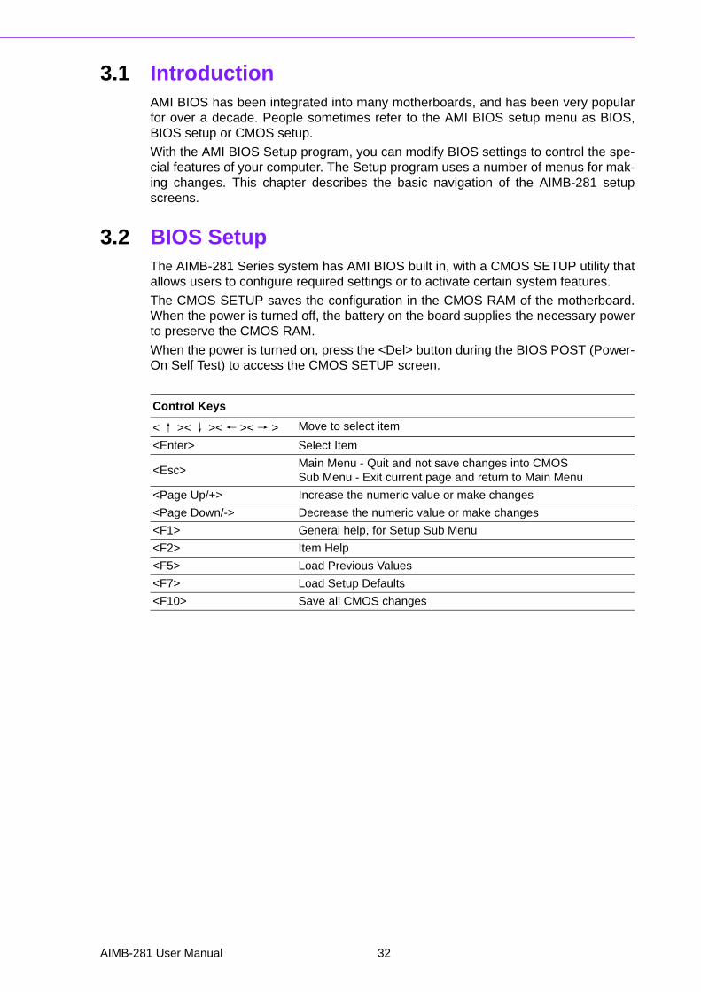
3.1 IntroductionAMI BIOS has been integrated into many motherboards, and has been very popularfor over a decade. People sometimes refer to the AMI BIOS setup menu as BIOS,BIOS setup or CMOS setup.
With the AMI BIOS Setup program, you can modify BIOS settings to control the spe-cial features of your computer. The Setup program uses a number of menus for mak-ing changes. This chapter describes the basic navigation of the AIMB-281 setupscreens.
3.2 BIOS SetupThe AIMB-281 Series system has AMI BIOS built in, with a CMOS SETUP utility thatallows users to configure required settings or to activate certain system features.
The CMOS SETUP saves the configuration in the CMOS RAM of the motherboard.When the power is turned off, the battery on the board supplies the necessary powerto preserve the CMOS RAM.
When the power is turned on, press the <Del> button during the BIOS POST (Power-On Self Test) to access the CMOS SETUP screen.
Control Keys
< ↑ >< ↓ >< ← >< → > Move to select item
<Enter> Select Item
<Esc>Main Menu - Quit and not save changes into CMOSSub Menu - Exit current page and return to Main Menu
<Page Up/+> Increase the numeric value or make changes
<Page Down/-> Decrease the numeric value or make changes
<F1> General help, for Setup Sub Menu
<F2> Item Help
<F5> Load Previous Values
<F7> Load Setup Defaults
<F10> Save all CMOS changes
AIMB-281 User Manual 32
Chapter 3
BIO
S O
peration
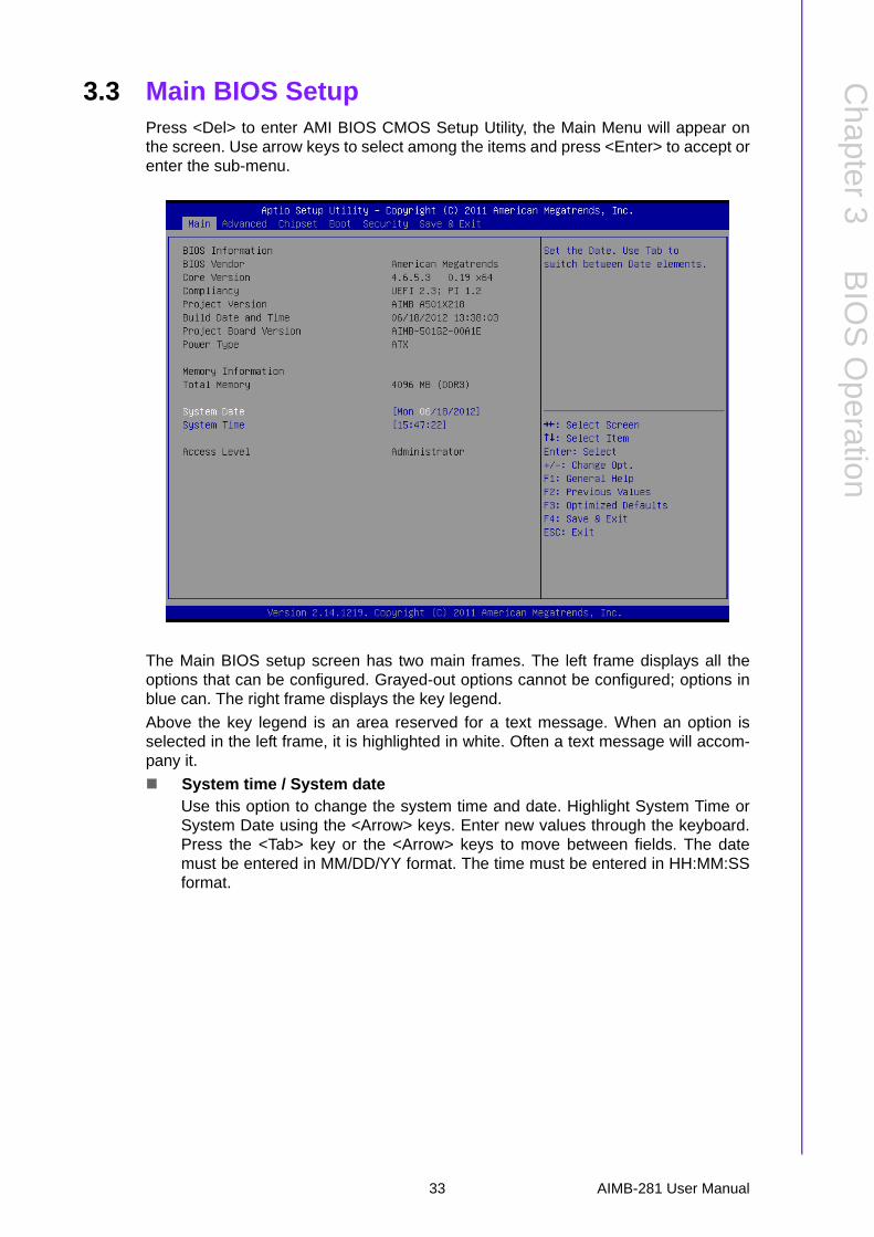
3.3 Main BIOS SetupPress <Del> to enter AMI BIOS CMOS Setup Utility, the Main Menu will appear onthe screen. Use arrow keys to select among the items and press <Enter> to accept orenter the sub-menu.
The Main BIOS setup screen has two main frames. The left frame displays all theoptions that can be configured. Grayed-out options cannot be configured; options inblue can. The right frame displays the key legend.
Above the key legend is an area reserved for a text message. When an option isselected in the left frame, it is highlighted in white. Often a text message will accom-pany it.
System time / System dateUse this option to change the system time and date. Highlight System Time orSystem Date using the <Arrow> keys. Enter new values through the keyboard.Press the <Tab> key or the <Arrow> keys to move between fields. The datemust be entered in MM/DD/YY format. The time must be entered in HH:MM:SSformat.
33 AIMB-281 User Manual

3.3.1 Advanced BIOS FeaturesSelect the Advanced tab from the AIMB-281 setup screen to enter the AdvancedBIOS Setup screen. You can select any of the items in the left frame of the screen,such as CPU Configuration, to go to the sub menu for that item. You can display anAdvanced BIOS Setup option by highlighting it using the <Arrow> keys. All AdvancedBIOS Setup options are described in this section. The Advanced BIOS Setup screenis shown below. The sub menus are described on the following pages.
AIMB-281 User Manual 34
Chapter 3
BIO
S O
peration
3.3.2 PCI Express Settings
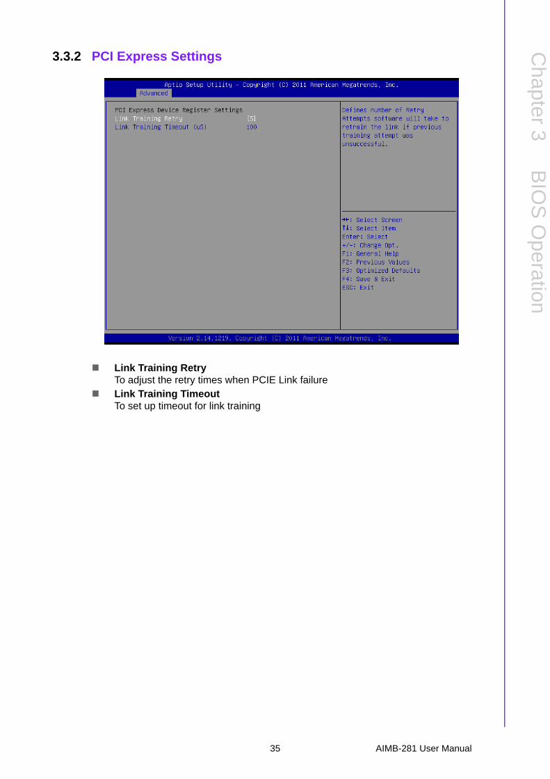
Link Training RetryTo adjust the retry times when PCIE Link failure
Link Training TimeoutTo set up timeout for link training
35 AIMB-281 User Manual
3.3.3 ACPI settings
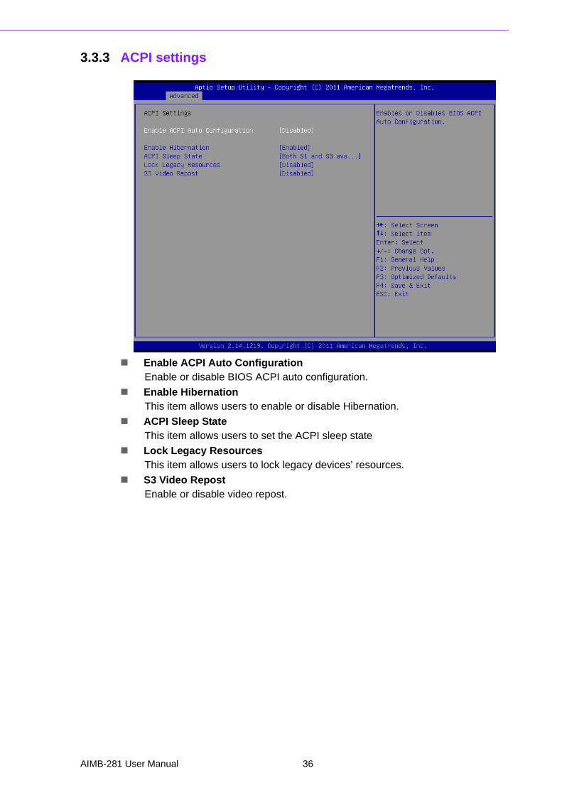
Enable ACPI Auto ConfigurationEnable or disable BIOS ACPI auto configuration.
Enable HibernationThis item allows users to enable or disable Hibernation.
ACPI Sleep StateThis item allows users to set the ACPI sleep state
Lock Legacy ResourcesThis item allows users to lock legacy devices’ resources.
S3 Video RepostEnable or disable video repost.
AIMB-281 User Manual 36
Chapter 3
BIO
S O
peration
3.3.4 Trusted Computing
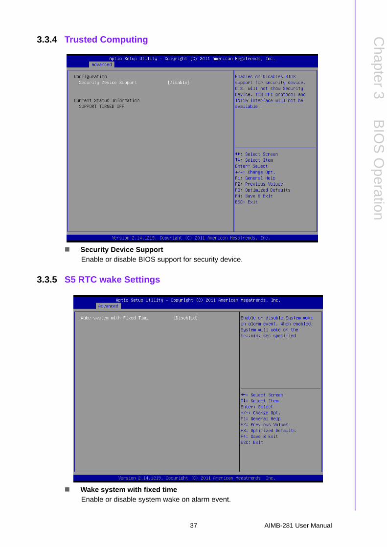
Security Device SupportEnable or disable BIOS support for security device.
3.3.5 S5 RTC wake Settings
Wake system with fixed timeEnable or disable system wake on alarm event.
37 AIMB-281 User Manual
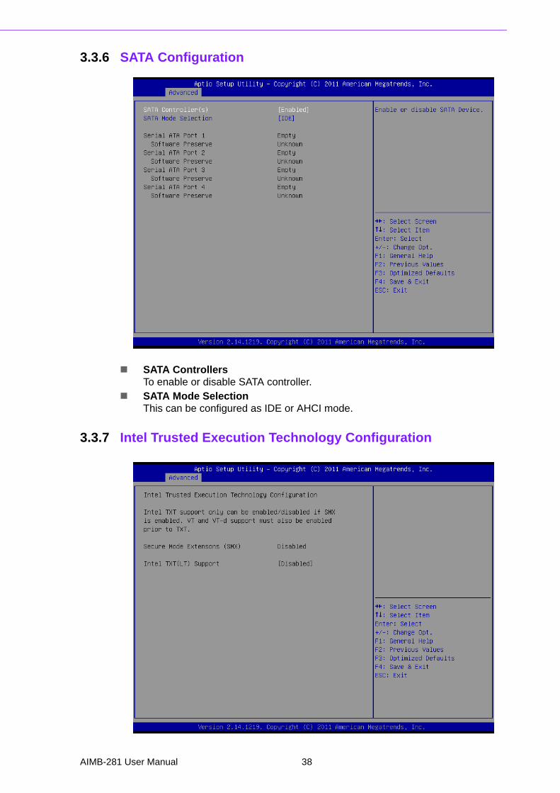
3.3.6 SATA Configuration
SATA ControllersTo enable or disable SATA controller.
SATA Mode Selection This can be configured as IDE or AHCI mode.
3.3.7 Intel Trusted Execution Technology Configuration
AIMB-281 User Manual 38
Chapter 3
BIO
S O
peration
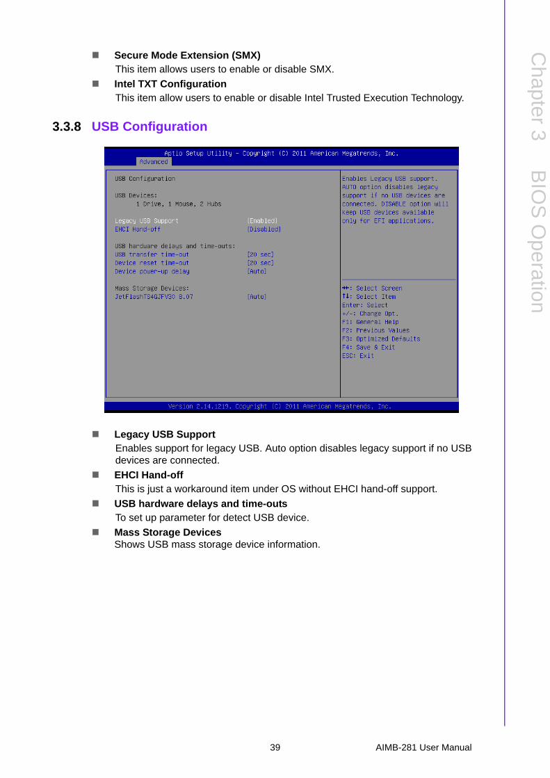
Secure Mode Extension (SMX)This item allows users to enable or disable SMX.
Intel TXT ConfigurationThis item allow users to enable or disable Intel Trusted Execution Technology.
3.3.8 USB Configuration
Legacy USB SupportEnables support for legacy USB. Auto option disables legacy support if no USBdevices are connected.
EHCI Hand-offThis is just a workaround item under OS without EHCI hand-off support.
USB hardware delays and time-outsTo set up parameter for detect USB device.
Mass Storage DevicesShows USB mass storage device information.
39 AIMB-281 User Manual
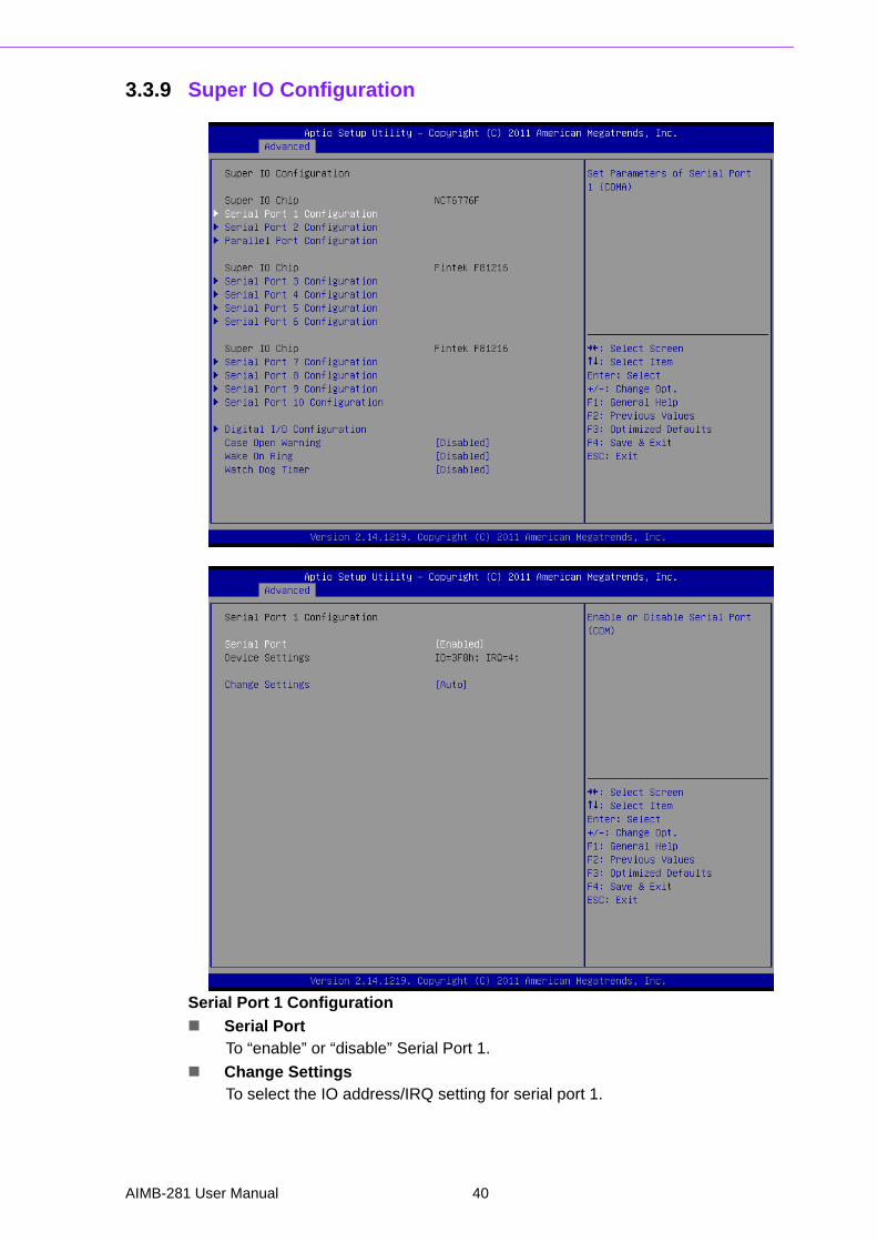
3.3.9 Super IO Configuration
Serial Port 1 Configuration
Serial PortTo “enable” or “disable” Serial Port 1.
Change SettingsTo select the IO address/IRQ setting for serial port 1.
AIMB-281 User Manual 40
Chapter 3
BIO
S O
peration
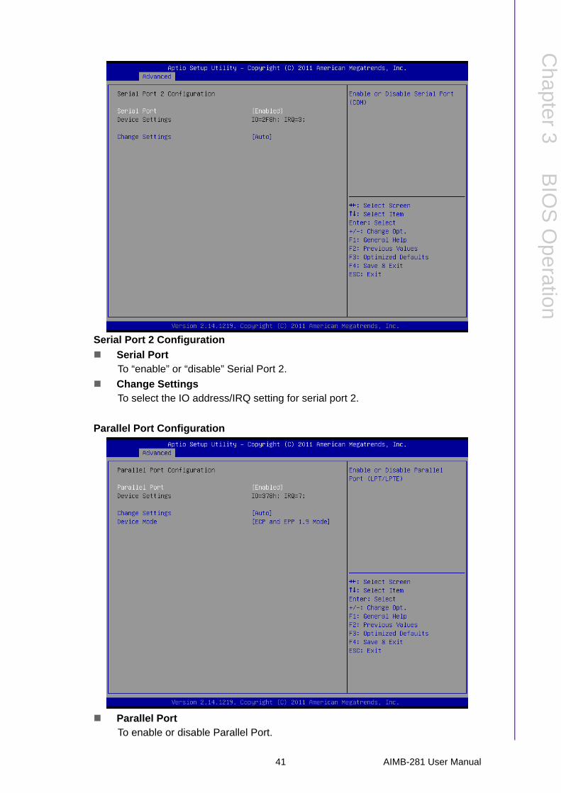
Serial Port 2 Configuration
Serial PortTo “enable” or “disable” Serial Port 2.
Change SettingsTo select the IO address/IRQ setting for serial port 2.
Parallel Port Configuration
Parallel PortTo enable or disable Parallel Port.
41 AIMB-281 User Manual

Super IO Configuration
Serial Port 3 Configuration
Serial PortTo “enable” or “disable” Serial Port 3.
Change SettingsTo select the IO address/IRQ setting for serial port 3.
Auto flow controlWhen the COM is to set as RS-485, it supports auto flow control function.
AIMB-281 User Manual 42
Chapter 3
BIO
S O
peration
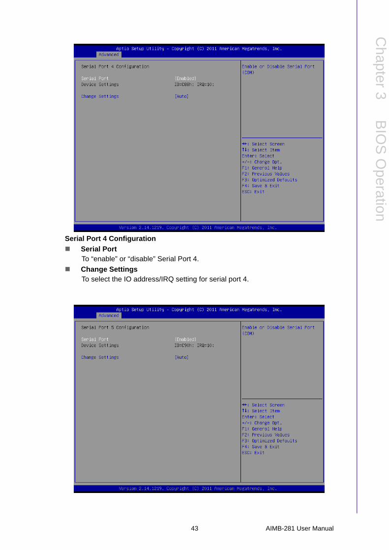
Serial Port 4 Configuration
Serial PortTo “enable” or “disable” Serial Port 4.
Change SettingsTo select the IO address/IRQ setting for serial port 4.
43 AIMB-281 User Manual
Serial Port 5 Configuration
Serial PortTo ‚”enable” or “disable” Serial Port 5.
Change SettingsTo select the IO address/IRQ setting for serial port 5.
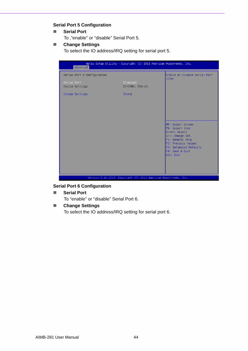
Serial Port 6 Configuration
Serial PortTo “enable” or “disable” Serial Port 6.
Change SettingsTo select the IO address/IRQ setting for serial port 6.
AIMB-281 User Manual 44

Chapter 3
BIO
S O
peration
3.3.10 Smart Fan Configuration
CPU Smart FanTo enable or disable CPU smart fan.
System Smart FanTo enable or disable System Smart Fan.
45 AIMB-281 User Manual
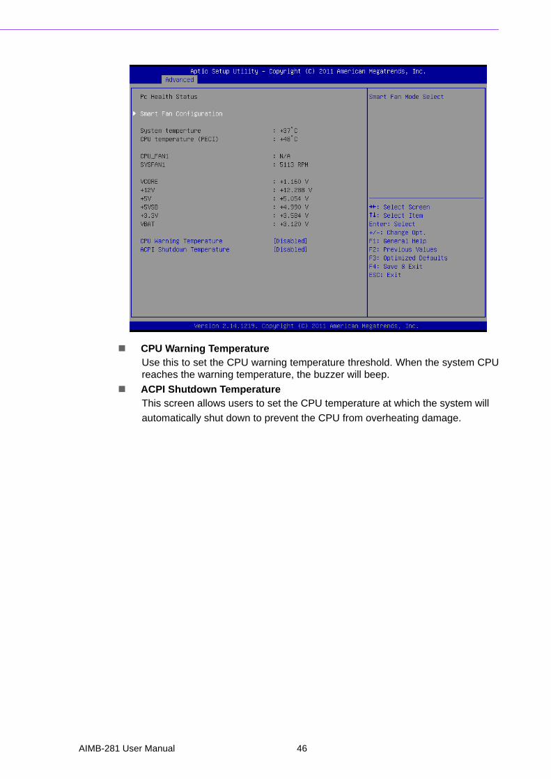
CPU Warning TemperatureUse this to set the CPU warning temperature threshold. When the system CPUreaches the warning temperature, the buzzer will beep.
ACPI Shutdown TemperatureThis screen allows users to set the CPU temperature at which the system will
automatically shut down to prevent the CPU from overheating damage.
AIMB-281 User Manual 46
Chapter 3
BIO
S O
peration
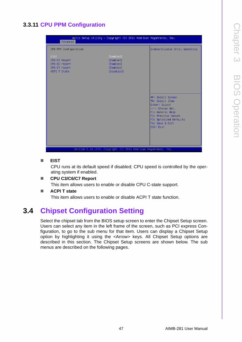
3.3.11 CPU PPM Configuration
EISTCPU runs at its default speed if disabled; CPU speed is controlled by the oper-ating system if enabled.
CPU C3/C6/C7 ReportThis item allows users to enable or disable CPU C-state support.
ACPI T stateThis item allows users to enable or disable ACPI T state function.
3.4 Chipset Configuration SettingSelect the chipset tab from the BIOS setup screen to enter the Chipset Setup screen.Users can select any item in the left frame of the screen, such as PCI express Con-figuration, to go to the sub menu for that item. Users can display a Chipset Setupoption by highlighting it using the <Arrow> keys. All Chipset Setup options aredescribed in this section. The Chipset Setup screens are shown below. The submenus are described on the following pages.
47 AIMB-281 User Manual
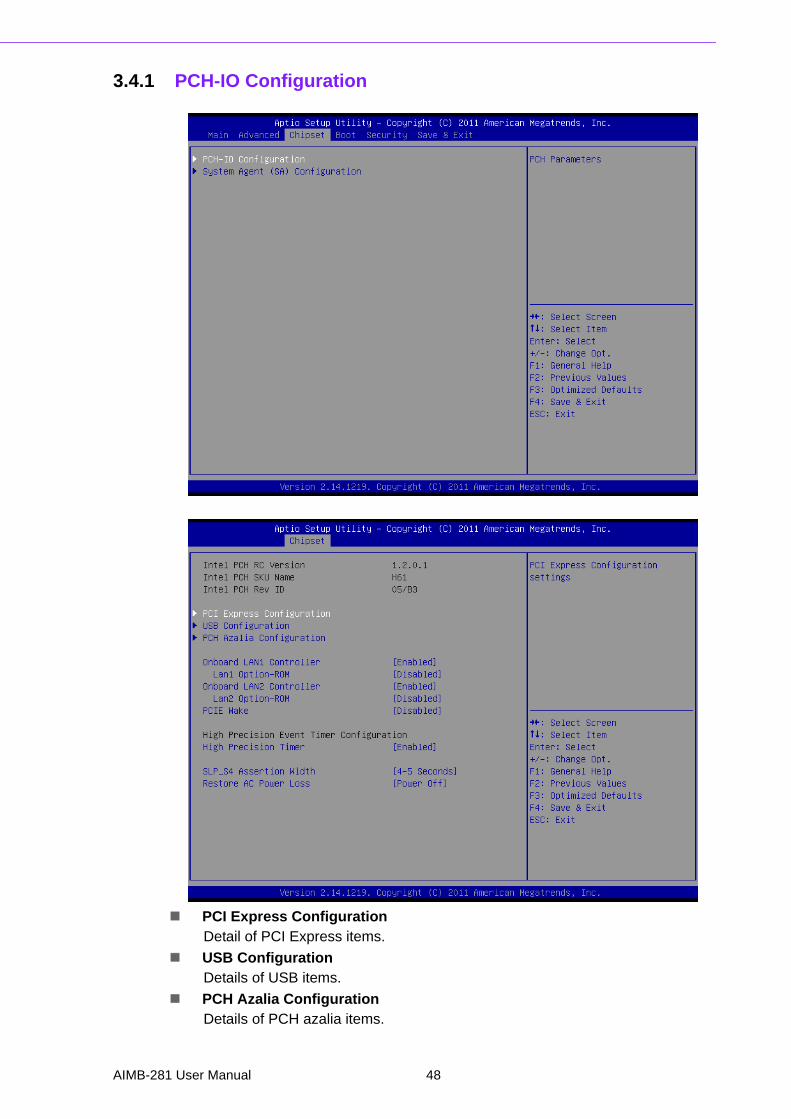
3.4.1 PCH-IO Configuration
PCI Express ConfigurationDetail of PCI Express items.
USB ConfigurationDetails of USB items.
PCH Azalia ConfigurationDetails of PCH azalia items.
AIMB-281 User Manual 48
Chapter 3
BIO
S O
peration
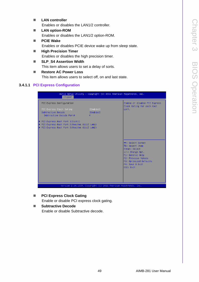
LAN controllerEnables or disables the LAN1/2 controller.
LAN option-ROMEnables or disables the LAN1/2 option-ROM.
PCIE WakeEnables or disables PCIE device wake up from sleep state.
High Precision TimerEnables or disables the high precision timer.
SLP_S4 Assertion WidthThis item allows users to set a delay of sorts.
Restore AC Power LossThis item allows users to select off, on and last state.
3.4.1.1 PCI Express Configuration
PCI Express Clock GatingEnable or disable PCI express clock gating.
Subtractive DecodeEnable or disable Subtractive decode.
49 AIMB-281 User Manual
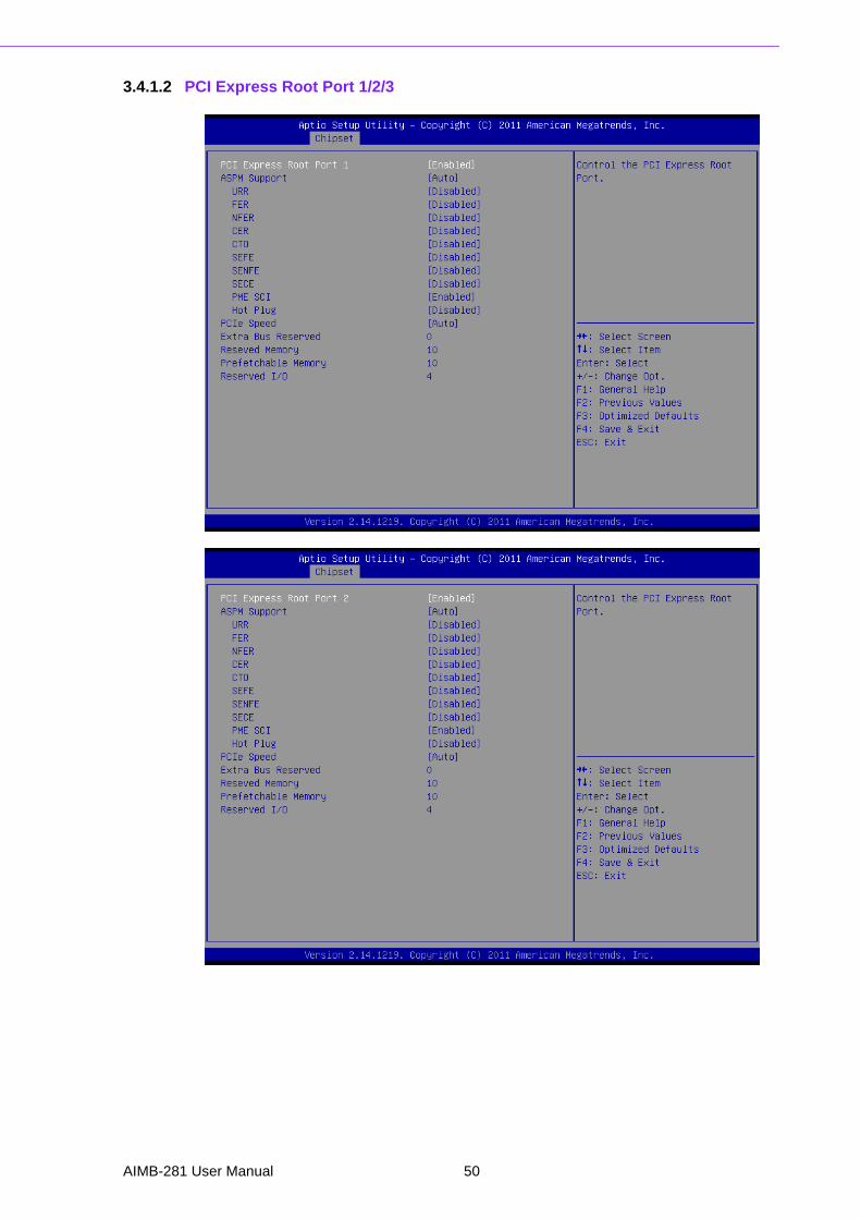
3.4.1.2 PCI Express Root Port 1/2/3
AIMB-281 User Manual 50
Chapter 3
BIO
S O
peration
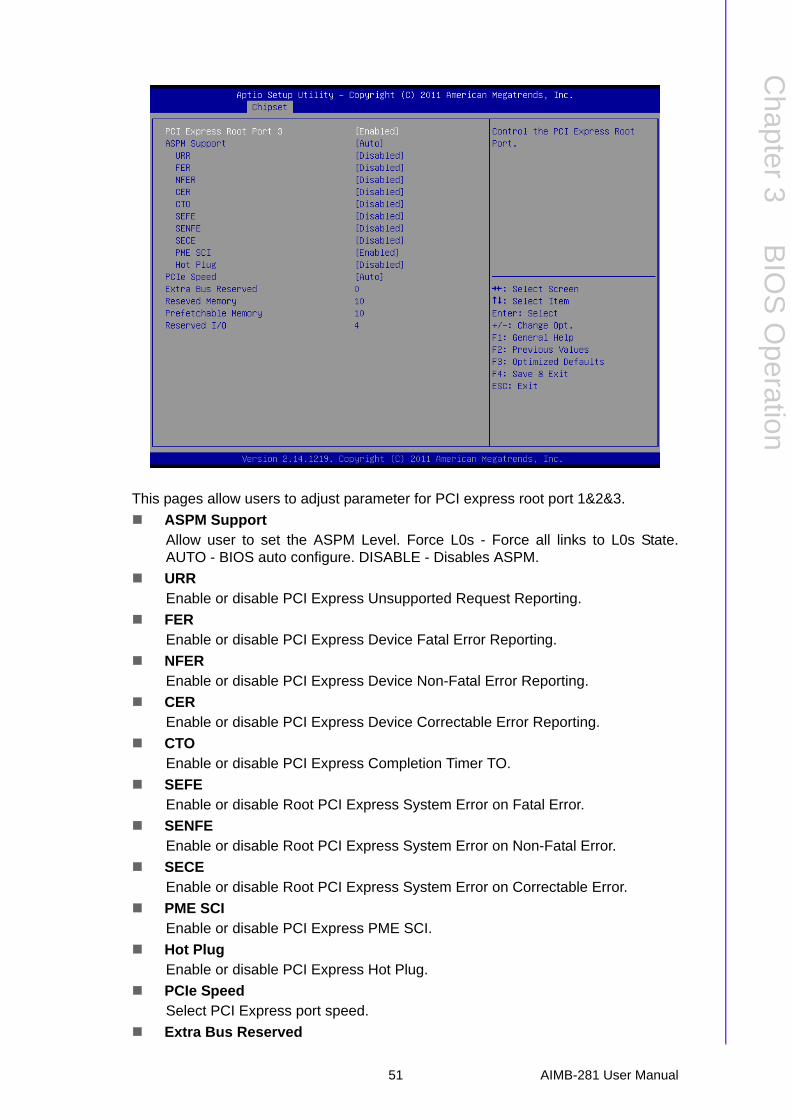
This pages allow users to adjust parameter for PCI express root port 1&2&3.
ASPM SupportAllow user to set the ASPM Level. Force L0s - Force all links to L0s State.AUTO - BIOS auto configure. DISABLE - Disables ASPM.
URREnable or disable PCI Express Unsupported Request Reporting.
FEREnable or disable PCI Express Device Fatal Error Reporting.
NFEREnable or disable PCI Express Device Non-Fatal Error Reporting.
CEREnable or disable PCI Express Device Correctable Error Reporting.
CTO Enable or disable PCI Express Completion Timer TO.
SEFEEnable or disable Root PCI Express System Error on Fatal Error.
SENFEEnable or disable Root PCI Express System Error on Non-Fatal Error.
SECEEnable or disable Root PCI Express System Error on Correctable Error.
PME SCIEnable or disable PCI Express PME SCI.
Hot Plug Enable or disable PCI Express Hot Plug.
PCIe Speed Select PCI Express port speed.
Extra Bus Reserved
51 AIMB-281 User Manual
Extra Bus Reserved for bridges behind this Root Bridge.
Reserved MemoryReserved Memory Range for this Root Bridge.
Prefetchable Memory Prefetchable Memory Range for this Root Bridge.
Reserved I/OReserved I/O (4K/8K/12K/16K/20K) Range for this Root Bridge
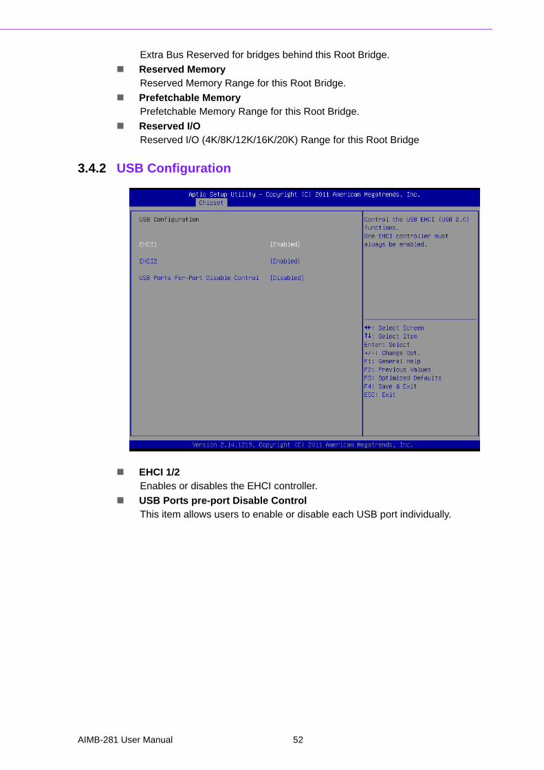
3.4.2 USB Configuration
EHCI 1/2Enables or disables the EHCI controller.
USB Ports pre-port Disable ControlThis item allows users to enable or disable each USB port individually.
AIMB-281 User Manual 52
Chapter 3
BIO
S O
peration
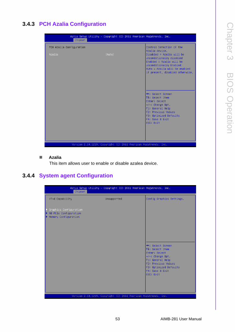
3.4.3 PCH Azalia Configuration
AzaliaThis item allows user to enable or disable azalea device.
3.4.4 System agent Configuration
53 AIMB-281 User Manual
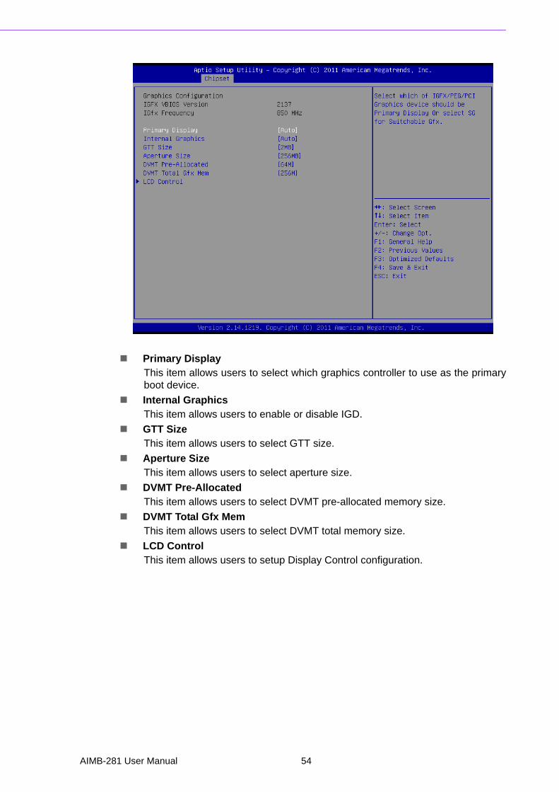
Primary DisplayThis item allows users to select which graphics controller to use as the primaryboot device.
Internal GraphicsThis item allows users to enable or disable IGD.
GTT SizeThis item allows users to select GTT size.
Aperture SizeThis item allows users to select aperture size.
DVMT Pre-AllocatedThis item allows users to select DVMT pre-allocated memory size.
DVMT Total Gfx MemThis item allows users to select DVMT total memory size.
LCD ControlThis item allows users to setup Display Control configuration.
AIMB-281 User Manual 54
Chapter 3
BIO
S O
peration
3.4.4.1 LCD Control configuration
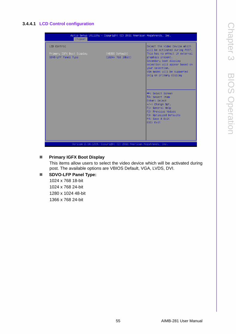
Primary IGFX Boot DisplayThis items allow users to select the video device which will be activated duringpost. The available options are VBIOS Default, VGA, LVDS, DVI.
SDVO-LFP Panel Type:1024 x 768 18-bit
1024 x 768 24-bit
1280 x 1024 48-bit
1366 x 768 24-bit
55 AIMB-281 User Manual

3.4.5 NB PCIe Configuration
PEG0 - Gen xSelect PEG0 speed.
– PEG0 ASPM=> Enable/Disable PEG0 ASPM function. (ASPM: Active State Power Management)
Enable PEGThis item allows users to enable or disable PEG always.
Detect Non-Compliance DeviceThis item allows users to enable or disable Detect Non-Compliance Devicefunction.
AIMB-281 User Manual 56
Chapter 3
BIO
S O
peration
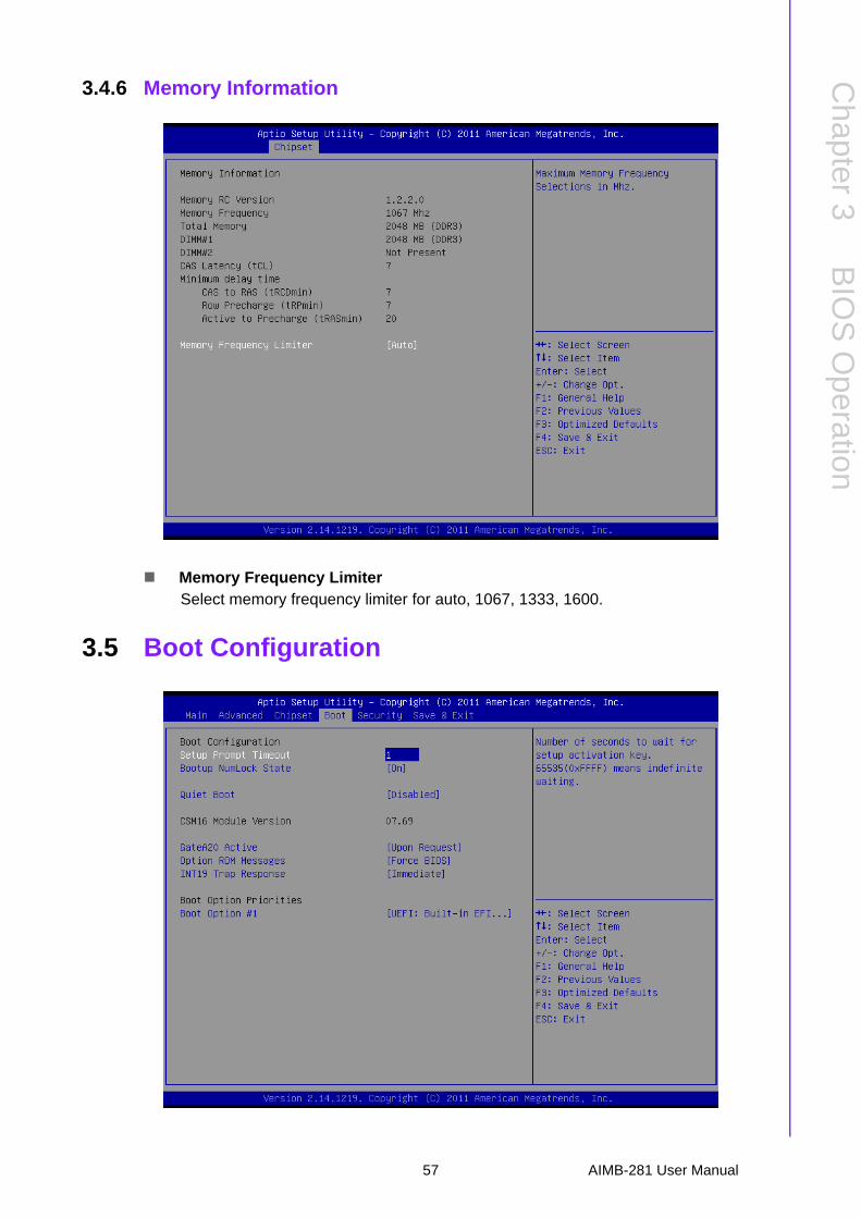
3.4.6 Memory Information
Memory Frequency LimiterSelect memory frequency limiter for auto, 1067, 1333, 1600.
3.5 Boot Configuration
57 AIMB-281 User Manual
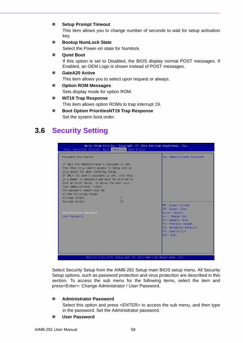
Setup Prompt TimeoutThis item allows you to change number of seconds to wait for setup activationkey.
Bootup NumLock StateSelect the Power-on state for Numlock.
Quiet BootIf this option is set to Disabled, the BIOS display normal POST messages. IfEnabled, an OEM Logo is shown instead of POST messages.
GateA20 Active This item allows you to select upon request or always.
Option ROM Messages Sets display mode for option ROM.
INT19 Trap Response This item allows option ROMs to trap interrupt 19.
Boot Option PrioritiesNT19 Trap Response Set the system boot order.
3.6 Security Setting
Select Security Setup from the AIMB-281 Setup main BIOS setup menu. All SecuritySetup options, such as password protection and virus protection are described in thissection. To access the sub menu for the following items, select the item andpress<Enter>: Change Administrator / User Password.
Administrator PasswordSelect this option and press <ENTER> to access the sub menu, and then typein the password. Set the Administrator password.
User Password
AIMB-281 User Manual 58
Chapter 3
BIO
S O
peration
Select this option and press <ENTER> to access the sub menu, and then typein the password. Set the User Password.
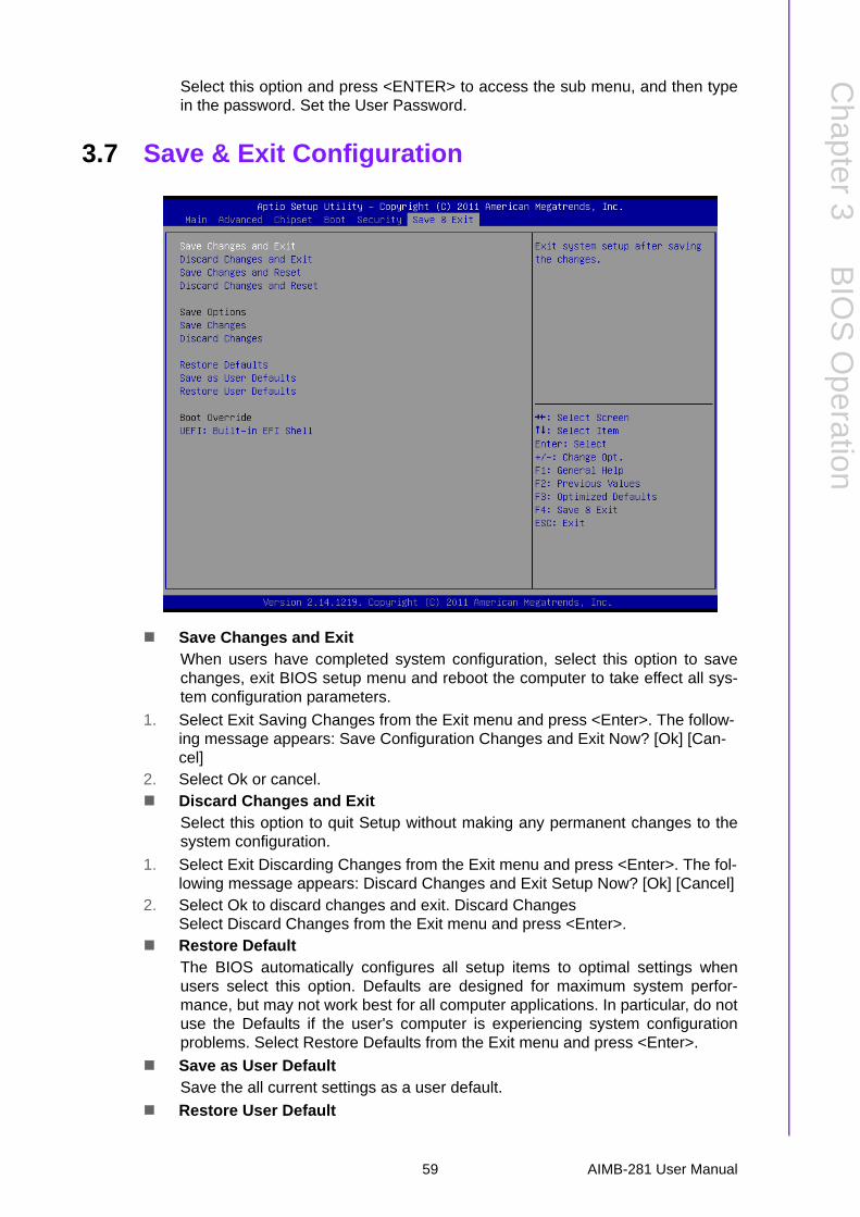
3.7 Save & Exit Configuration
Save Changes and ExitWhen users have completed system configuration, select this option to savechanges, exit BIOS setup menu and reboot the computer to take effect all sys-tem configuration parameters.
1. Select Exit Saving Changes from the Exit menu and press <Enter>. The follow-ing message appears: Save Configuration Changes and Exit Now? [Ok] [Can-cel]
2. Select Ok or cancel. Discard Changes and Exit
Select this option to quit Setup without making any permanent changes to thesystem configuration.
1. Select Exit Discarding Changes from the Exit menu and press <Enter>. The fol-lowing message appears: Discard Changes and Exit Setup Now? [Ok] [Cancel]
2. Select Ok to discard changes and exit. Discard ChangesSelect Discard Changes from the Exit menu and press <Enter>.
Restore DefaultThe BIOS automatically configures all setup items to optimal settings whenusers select this option. Defaults are designed for maximum system perfor-mance, but may not work best for all computer applications. In particular, do notuse the Defaults if the user's computer is experiencing system configurationproblems. Select Restore Defaults from the Exit menu and press <Enter>.
Save as User DefaultSave the all current settings as a user default.
Restore User Default
59 AIMB-281 User Manual

Restore all settings to user default values.
Boot OverrideShows the boot device types on the system.
AIMB-281 User Manual 60
Chapter 4
4 Chipset Software Installation Utility
4.1 Before You BeginTo facilitate the installation of the enhanced display drivers and utility software, readthe instructions in this chapter carefully. The drivers for AIMB-281 are located on thesoftware installation CD. The driver in the folder of the driver CD will guide and linkyou to the utilities and drivers under a Windows system. Updates are provided viaService Packs from Microsoft*.
Before you begin, it is important to note that most display drivers need to have therelevant software application already installed in the system prior to installing theenhanced display drivers. In addition, many of the installation procedures assumethat you are familiar with both the relevant software applications and operating sys-tem commands. Review the relevant operating system commands and the pertinentsections of your application software’s user manual before performing the installa-tion.
4.2 IntroductionThe Intel Chipset Software Installation (CSI) utility installs the Windows INF files thatoutline to the operating system how the chipset components will be configured. Thisis needed for the proper functioning of the following features:
Core PCI PnP services IDE Ultra ATA 100/66/33 and Serial ATA interface support USB 1.1/2.0 support (USB 2.0 driver needs to be installed separately for Win98) Identification of Intel chipset components in the Device Manager
Note! The files on the software installation CD are compressed. Do not attempt to install the drivers by copying the files manually. You must use the supplied SETUP program to install the drivers.
Note! This utility is used for the following versions of Windows, and it has to be installed before installing all the other drivers:
Windows 7 (32-bit) Windows 7 (64-bit) Windows XP professional edition (32-bit) Windows XP professional edition (64-bit)
AIMB-281 User Manual 62
Chapter 4
ChipsetS
oftware
Installation Utility
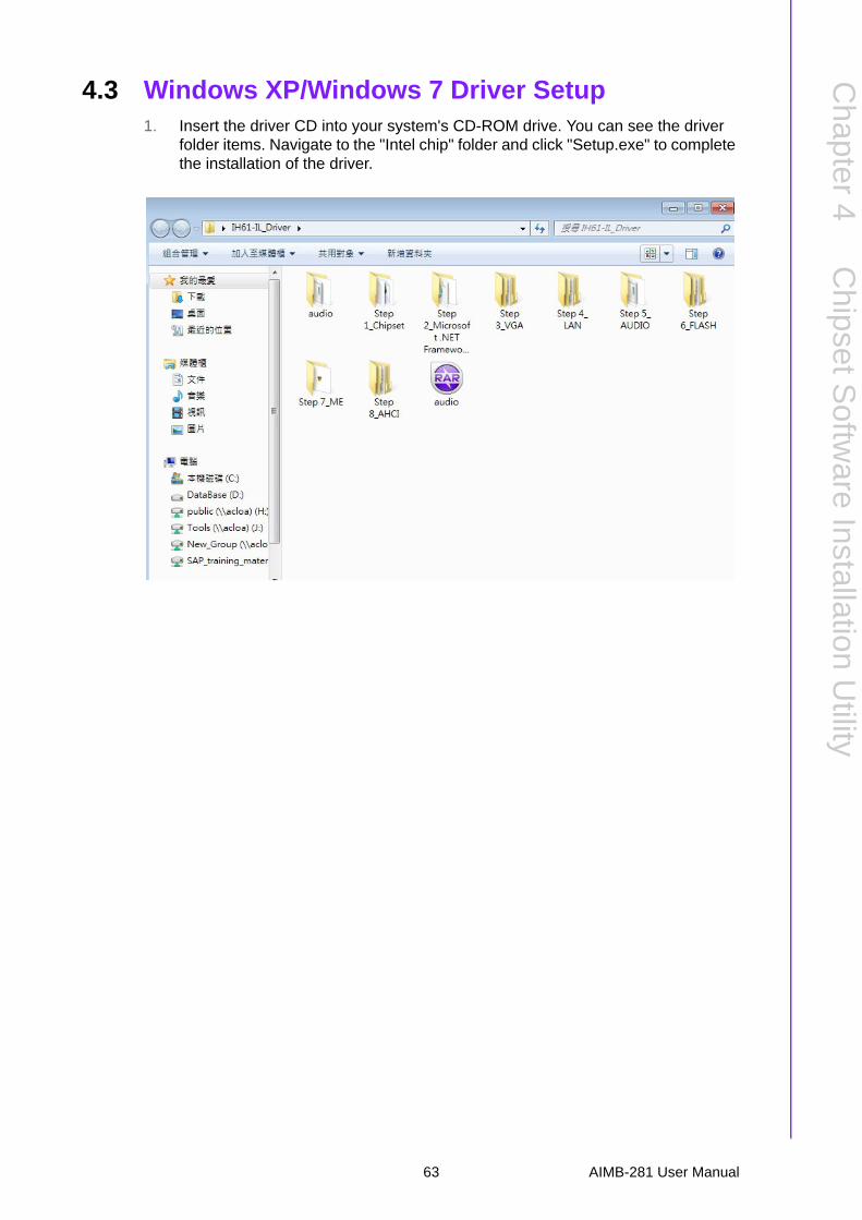
4.3 Windows XP/Windows 7 Driver Setup1. Insert the driver CD into your system's CD-ROM drive. You can see the driver
folder items. Navigate to the "Intel chip" folder and click "Setup.exe" to complete the installation of the driver.
63 AIMB-281 User Manual

AIMB-281 User Manual 64

Chapter 5
5 VGA Setup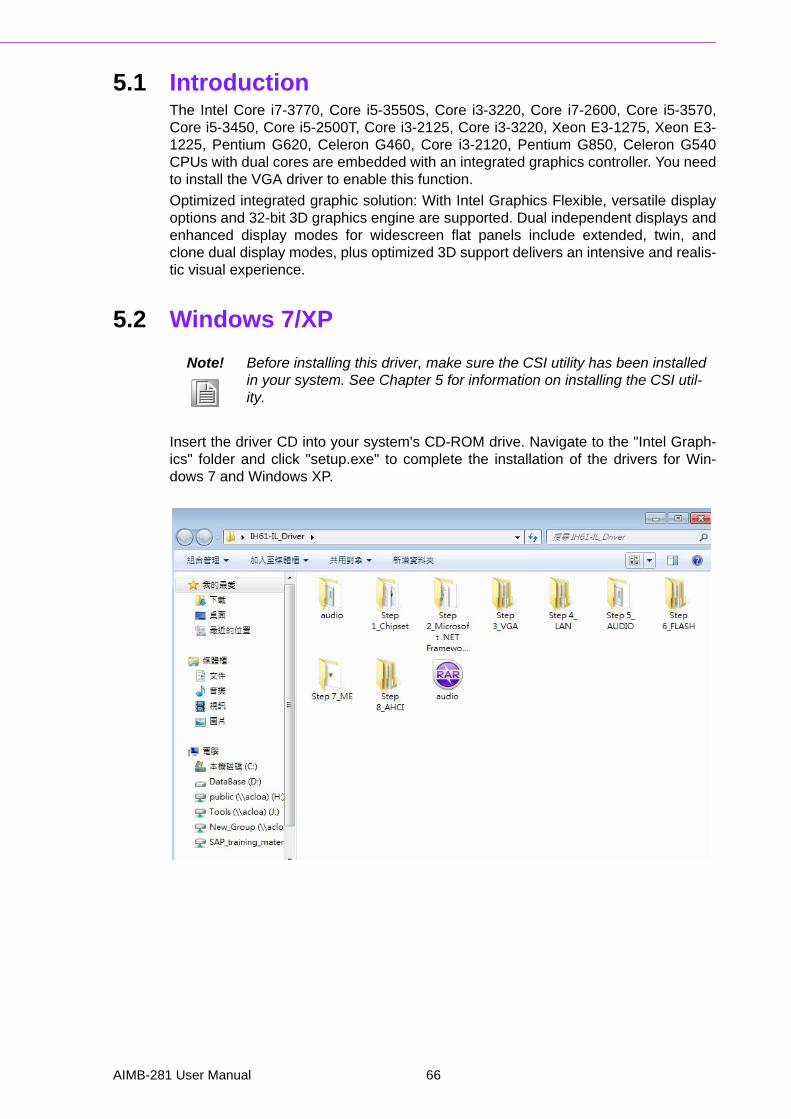
5.1 IntroductionThe Intel Core i7-3770, Core i5-3550S, Core i3-3220, Core i7-2600, Core i5-3570,Core i5-3450, Core i5-2500T, Core i3-2125, Core i3-3220, Xeon E3-1275, Xeon E3-1225, Pentium G620, Celeron G460, Core i3-2120, Pentium G850, Celeron G540CPUs with dual cores are embedded with an integrated graphics controller. You needto install the VGA driver to enable this function.
Optimized integrated graphic solution: With Intel Graphics Flexible, versatile displayoptions and 32-bit 3D graphics engine are supported. Dual independent displays andenhanced display modes for widescreen flat panels include extended, twin, andclone dual display modes, plus optimized 3D support delivers an intensive and realis-tic visual experience.
5.2 Windows 7/XP
Insert the driver CD into your system's CD-ROM drive. Navigate to the "Intel Graph-ics" folder and click "setup.exe" to complete the installation of the drivers for Win-dows 7 and Windows XP.
Note! Before installing this driver, make sure the CSI utility has been installed in your system. See Chapter 5 for information on installing the CSI util-ity.
AIMB-281 User Manual 66
Chapter 6
6 LAN Configuration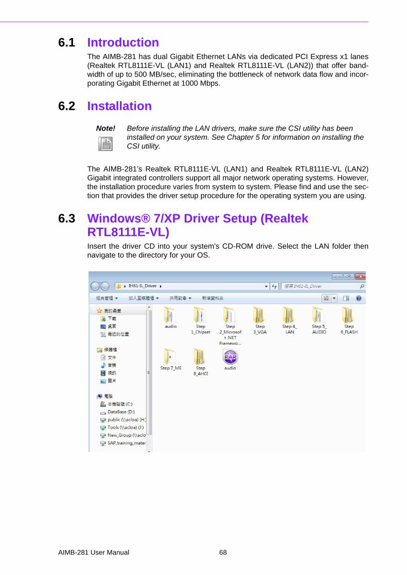
6.1 IntroductionThe AIMB-281 has dual Gigabit Ethernet LANs via dedicated PCI Express x1 lanes(Realtek RTL8111E-VL (LAN1) and Realtek RTL8111E-VL (LAN2)) that offer band-width of up to 500 MB/sec, eliminating the bottleneck of network data flow and incor-porating Gigabit Ethernet at 1000 Mbps.
6.2 Installation
The AIMB-281’s Realtek RTL8111E-VL (LAN1) and Realtek RTL8111E-VL (LAN2)Gigabit integrated controllers support all major network operating systems. However,the installation procedure varies from system to system. Please find and use the sec-tion that provides the driver setup procedure for the operating system you are using.
6.3 Windows® 7/XP Driver Setup (Realtek RTL8111E-VL)Insert the driver CD into your system's CD-ROM drive. Select the LAN folder thennavigate to the directory for your OS.
Note! Before installing the LAN drivers, make sure the CSI utility has been installed on your system. See Chapter 5 for information on installing the CSI utility.
AIMB-281 User Manual 68

Appendix A
A Programming the Watchdog Timer
A.1 Programming the Watchdog TimerAIMB-281's watchdog timer can be used to monitor system software operation andtake corrective action if the software fails to function within the programmed period.This section describes the operation of the watchdog timer and how to program it.
A.1.1 Watchdog Timer OverviewThe watchdog timer is built into the super I/O controller Nuvoton NCT6776F. It pro-vides the following user-programmable functions:
Can be enabled and disabled by user program Timer can be set from 1 to 255 seconds or 1 to 255 minutes Generates an interrupt or resets signal if the software fails to reset the timer
before time-out
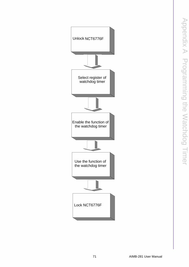
A.1.2 Programming the Watchdog TimerThe I/O port address of the watchdog timer is 2E (hex) and 2F (hex). 2E (hex) is theaddress port. 2F (hex) is the data port. You must first assign the address of registerby writing an address value into address port 2E (hex), then write/read data to/fromthe assigned register through data port 2F (hex).
AIMB-281 User Manual 70
Appendix A
Program
ming
theW
atchdogT
imer
Unlock
Select register of watchdog timer
Enable the function ofthe watchdog timer
Use the function of
Lock NCT6776F
the watchdog timer
NCT6776F
71 AIMB-281 User Manual
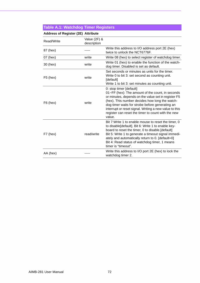
Table A.1: Watchdog Timer Registers
Address of Register (2E) Attribute
Read/WriteValue (2F) &description
87 (hex) -----Write this address to I/O address port 2E (hex) twice to unlock the NCT6776F.
07 (hex) write Write 08 (hex) to select register of watchdog timer.
30 (hex) writeWrite 01 (hex) to enable the function of the watch-dog timer. Disabled is set as default.
F5 (hex) write
Set seconds or minutes as units for the timer.Write 0 to bit 3: set second as counting unit. [default]Write 1 to bit 3: set minutes as counting unit.
F6 (hex) write
0: stop timer [default]01~FF (hex): The amount of the count, in seconds or minutes, depends on the value set in register F5 (hex). This number decides how long the watch-dog timer waits for strobe before generating an interrupt or reset signal. Writing a new value to this register can reset the timer to count with the new value.
F7 (hex) read/write
Bit 7:Write 1 to enable mouse to reset the timer, 0 to disable[default]. Bit 6: Write 1 to enable key-board to reset the timer, 0 to disable.[default] Bit 5: Write 1 to generate a timeout signal immedi-ately and automatically return to 0. [default=0]Bit 4: Read status of watchdog timer, 1 means timer is “timeout”.
AA (hex) -----Write this address to I/O port 2E (hex) to lock the watchdog timer 2.
AIMB-281 User Manual 72
Appendix A
Program
ming
theW
atchdogT
imer
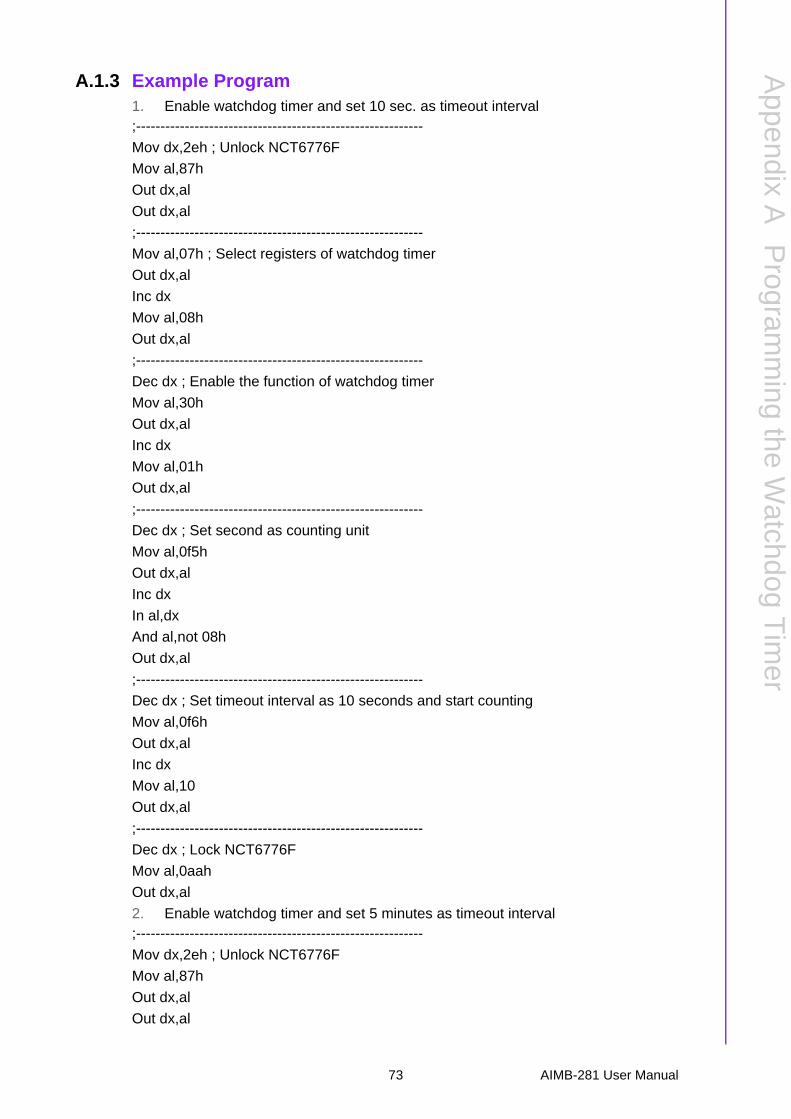
A.1.3 Example Program1. Enable watchdog timer and set 10 sec. as timeout interval;-----------------------------------------------------------
Mov dx,2eh ; Unlock NCT6776F
Mov al,87h
Out dx,al
Out dx,al
;-----------------------------------------------------------
Mov al,07h ; Select registers of watchdog timer
Out dx,al
Inc dx
Mov al,08h
Out dx,al
;-----------------------------------------------------------
Dec dx ; Enable the function of watchdog timer
Mov al,30h
Out dx,al
Inc dx
Mov al,01h
Out dx,al
;-----------------------------------------------------------
Dec dx ; Set second as counting unit
Mov al,0f5h
Out dx,al
Inc dx
In al,dx
And al,not 08h
Out dx,al
;-----------------------------------------------------------
Dec dx ; Set timeout interval as 10 seconds and start counting
Mov al,0f6h
Out dx,al
Inc dx
Mov al,10
Out dx,al
;-----------------------------------------------------------
Dec dx ; Lock NCT6776F
Mov al,0aah
Out dx,al
2. Enable watchdog timer and set 5 minutes as timeout interval;-----------------------------------------------------------
Mov dx,2eh ; Unlock NCT6776F
Mov al,87h
Out dx,al
Out dx,al
73 AIMB-281 User Manual
;-----------------------------------------------------------
Mov al,07h ; Select registers of watchdog timer
Out dx,al
Inc dx
Mov al,08h
Out dx,al
;-----------------------------------------------------------
Dec dx ; Enable the function of watchdog timer
Mov al,30h
Out dx,al
Inc dx
Mov al,01h
Out dx,al
;-----------------------------------------------------------
Dec dx ; Set minute as counting unit
Mov al,0f5h
Out dx,al
Inc dx
In al,dx
Or al,08h
Out dx,al
;-----------------------------------------------------------
Dec dx ; Set timeout interval as 5 minutes and start counting
Mov al,0f6h
Out dx,al
Inc dx
Mov al,5
Out dx,al
;-----------------------------------------------------------
Dec dx ; Lock NCT6776F
Mov al,0aah
Out dx,al
3. Enable watchdog timer to be reset by mouse;-----------------------------------------------------------
Mov dx,2eh ; Unlock NCT6776F
Mov al,87h
Out dx,al
Out dx,al
;-----------------------------------------------------------
Mov al,07h ; Select registers of watchdog timer
Out dx,al
Inc dx
Mov al,08h
Out dx,al
;-----------------------------------------------------------
AIMB-281 User Manual 74
Appendix A
Program
ming
theW
atchdogT
imer
Dec dx ; Enable the function of watchdog timer
Mov al,30h
Out dx,al
Inc dx
Mov al,01h
Out dx,al
;-----------------------------------------------------------
Dec dx ; Enable watchdog timer to be reset by mouse
Mov al,0f7h
Out dx,al
Inc dx
In al,dx
Or al,80h
Out dx,al
;-----------------------------------------------------------
Dec dx ; Lock NCT6776F
Mov al,0aah
Out dx,al
4. Enable watchdog timer to be reset by keyboard;-----------------------------------------------------------
Mov dx,2eh ; Unlock NCT6776F
Mov al,87h
Out dx,al
Out dx,al
;-----------------------------------------------------------
Mov al,07h ; Select registers of watchdog timer
Out dx,al
Inc dx
Mov al,08h
Out dx,al
;-----------------------------------------------------------
Dec dx ; Enable the function of watchdog timer
Mov al,30h
Out dx,al
Inc dx
Mov al,01h
Out dx,al
;-----------------------------------------------------------
Dec dx ; Enable watchdog timer to be strobed reset by keyboard
Mov al,0f7h
Out dx,al
Inc dx
In al,dx
Or al,40h
Out dx,al
75 AIMB-281 User Manual
;-----------------------------------------------------------
Dec dx ; Lock NCT6776F
Mov al,0aah
Out dx,al
5. Generate a time-out signal without timer counting;-----------------------------------------------------------
Mov dx,2eh ; Unlock NCT6776F
Mov al,87h
Out dx,al
Out dx,al
;-----------------------------------------------------------
Mov al,07h ; Select registers of watchdog timer
Out dx,al
Inc dx
Mov al,08h
Out dx,al
;-----------------------------------------------------------
Dec dx ; Enable the function of watchdog timer
Mov al,30h
Out dx,al
Inc dx
Mov al,01h
Out dx,al
;-----------------------------------------------------------
Dec dx ; Generate a time-out signal
Mov al,0f7h
Out dx,al ;Write 1 to bit 5 of F7 register
Inc dx
In al,dx
Or al,20h
Out dx,al
;-----------------------------------------------------------
Dec dx ; Lock NCT6776F
Mov al,0aah
Out dx,al
AIMB-281 User Manual 76

Appendix A
Program
ming
theW
atchdogT
imer
77 AIMB-281 User Manual

www.advantech.comPlease verify specifications before quoting. This guide is intended for referencepurposes only.All product specifications are subject to change without notice.No part of this publication may be reproduced in any form or by any means,electronic, photocopying, recording or otherwise, without prior written permis-sion of the publisher.All brand and product names are trademarks or registered trademarks of theirrespective companies.© Advantech Co., Ltd. 2014