Embed Size (px)
Citation preview

7425MUM020 Rev00 CANADA
REFRIGERATED AIR DRYER
SÉCHEUR A CYCLE FRIGORIFIQUE
AHT 20 to AHT 350
USER’S MAINTENANCE
MANUEL D’INSTRUCTIONS ENTRETIEN
AIR - COOLED
REFROIDISSEMENT A AIR
ISSUE •••• EDITION 2007
F
GB
F
GB
GB
Dear Customer,
thank you for choosing our product. In order to get the best performances out of this product, please read this manual carefully.
To avoid incorrect operation of the equipment and possible physical risk to the operator, please read and strictly follow the instructions contained in this manual.
Note, these instructions are in addition to the safety rules that apply in the country where the dryer is installed. Before packing for shipment each AHT series refrigerated air dryer undergoes a rigorous test to ensure the absence of any manufacturing faults and to demonstrate that the device can perform all the functions for which it has been designed.
Once the dryer has been properly installed according to the instructions in this manual, it will be ready for use without any further adjustment. The operation is fully automatic, and the maintenance is limited to few controls and some cleaning operations, as detailed in the following chapters.
This manual must be maintained available in any moment for future references and it has to be intended as inherent part of the relevant dryer.
Due to the continuous technical evolution, we reserve the right to introduce any necessary change without giving previous notice.
Should you experience any trouble, or for further information, please do not hesitate to contact us.
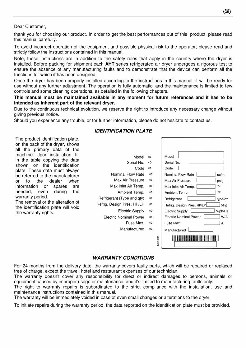
IDENTIFICATION PLATE
Model �
Serial No. �
Code �
Nominal Flow Rate �
Max Air Pressure �
Max Inlet Air Temp. �
Ambient Temp. �
Refrigerant (Type and qty) �
Refrig. Design Pres. HP/LP �
Electric Supply �
Electric Nominal Power �
Fuse Max. �
Manufactured �
The product identification plate, on the back of the dryer, shows all the primary data of the machine. Upon installation, fill in the table copying the data shown on the identification plate. These data must always be referred to the manufacturer or to the dealer when information or spares are needed, even during the warranty period. The removal or the alteration of the identification plate will void the warranty rights.
TA
D00
04
Refrig. Design Pres. HP/LP
Max Inlet Air Temp.
Electric Supply
Manufactured
Fuse Max.
Electric Nominal Power
Refrigerant
Ambient Temp.
Nominal Flow Rate
Max Air Pressure
Code
Serial No.
Model
°F
V/ph/Hz
A
W/A
type/oz
psig
°F
scfm
psig
WARRANTY CONDITIONS
For 24 months from the delivery date, the warranty covers faulty parts, which will be repaired or replaced free of charge, except the travel, hotel and restaurant expenses of our technician. The warranty doesn’t cover any responsibility for direct or indirect damages to persons, animals or equipment caused by improper usage or maintenance, and it’s limited to manufacturing faults only. The right to warranty repairs is subordinated to the strict compliance with the installation, use and maintenance instructions contained in this manual. The warranty will be immediately voided in case of even small changes or alterations to the dryer.
To initiate repairs during the warranty period, the data reported on the identification plate must be provided.

GB
1. SAFETY RULES
1.1 Definition of the Conventional Signs Used in This Manual 1.2 Warnings 1.3 Proper Use of the Dryer 1.4 Instructions for the use of pressure equipment according to PED Directive 97/23/EC
2. INSTALLATION
2.1 Transport 2.2 Storage 2.3 Installation site 2.4 Installation layout 2.5 Correction factors 2.6 Connection to the Compressed Air System 2.7 Electrical connections 2.8 Condensate Drain
3. START UP
3.1 Preliminary Operations 3.2 First Start-up 3.3 Start-up and Shut down
4. TECHNICAL SPECIFICATIONS
4.1 Technical Specifications AHT 20-150 -1 (115/1/60) 4.2 Technical Specifications AHT 20-350 -2 (230/1/60)
5. TECHNICAL DESCRIPTION
5.1 Control panel 5.2 Operation 5.3 Flow Diagram (Air-Cooled) 5.4 Refrigerating compressor 5.5 Condenser 5.6 Filter Drier 5.7 Aftercooler 5.8 Pre-filter (3 micron) 5.9 Capillary Tube 5.10 Alu-Dry Module 5.11 Hot Gas By-pass Valve 5.12 Refrigerant Pressure Switches PA-PB-PV 5.13 Safety thermo-switch TS 5.14 DMC14 Electronic instrument (Air Dryer Controller) 5.15 Electronic level controlled condensate drain Bekomat 31 AHT 20-100 5.16 Electronic level controlled condensate drain Bekomat 32 AHT 150-350 5.17 Maintenance BEKOMAT
6. MAINTENANCE, TROUBLESHOOTING, DISMANTLING
6.1 Controls and Maintenance 6.2 Troubleshooting 6.3 Maintenance operation on the refrigerating circuit 6.4 Dismantling of the Dryer
7. LIST OF ATTACHMENTS
7.1 Dryers Dimensions 7.2 Exploded View 7.3 Electric Diagrams
GB
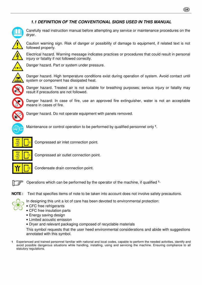
1.1 DEFINITION OF THE CONVENTIONAL SIGNS USED IN THIS MANUAL
Carefully read instruction manual before attempting any service or maintenance procedures on the dryer.
Caution warning sign. Risk of danger or possibility of damage to equipment, if related text is not followed properly.
Electrical hazard. Warning message indicates practices or procedures that could result in personal injury or fatality if not followed correctly.
Danger hazard. Part or system under pressure.
Danger hazard. High temperature conditions exist during operation of system. Avoid contact until system or component has dissipated heat.
Danger hazard. Treated air is not suitable for breathing purposes; serious injury or fatality may result if precautions are not followed.
Danger hazard: In case of fire, use an approved fire extinguisher, water is not an acceptable means in cases of fire.
Danger hazard. Do not operate equipment with panels removed.
Maintenance or control operation to be performed by qualified personnel only 1.
ARIAAIR
LUFTAIR
Compressed air inlet connection point.
ARIAAIR
LUFTAIR
Compressed air outlet connection point.
Condensate drain connection point.
Operations which can be performed by the operator of the machine, if qualified 1.
NOTE : Text that specifies items of note to be taken into account does not involve safety precautions.
In designing this unit a lot of care has been devoted to environmental protection:
• CFC free refrigerants
• CFC free insulation parts
• Energy saving design
• Limited acoustic emission
• Dryer and relevant packaging composed of recyclable materials
This symbol requests that the user heed environmental considerations and abide with suggestions annotated with this symbol.
1 Experienced and trained personnel familiar with national and local codes, capable to perform the needed activities, identify and avoid possible dangerous situations while handling, installing, using and servicing the machine. Ensuring compliance to all statutory regulations.
GB
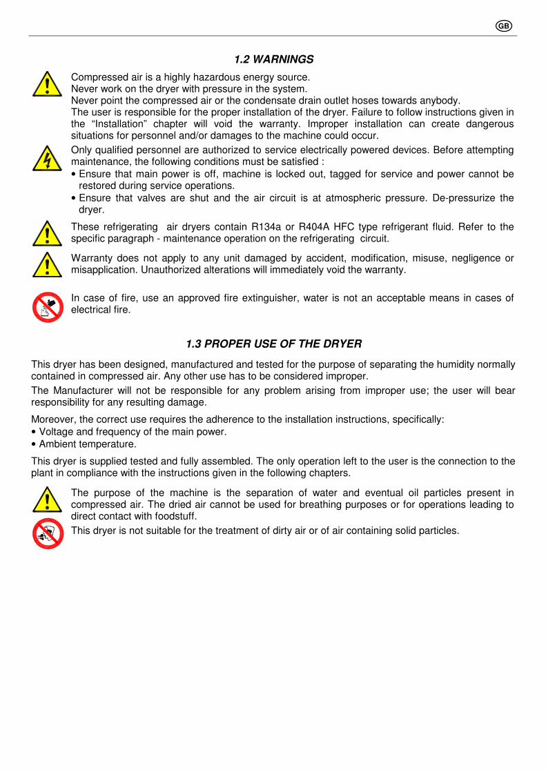
1.2 WARNINGS
Compressed air is a highly hazardous energy source. Never work on the dryer with pressure in the system. Never point the compressed air or the condensate drain outlet hoses towards anybody. The user is responsible for the proper installation of the dryer. Failure to follow instructions given in the “Installation” chapter will void the warranty. Improper installation can create dangerous situations for personnel and/or damages to the machine could occur.
Only qualified personnel are authorized to service electrically powered devices. Before attempting maintenance, the following conditions must be satisfied :
• Ensure that main power is off, machine is locked out, tagged for service and power cannot be restored during service operations.
• Ensure that valves are shut and the air circuit is at atmospheric pressure. De-pressurize the dryer.
These refrigerating air dryers contain R134a or R404A HFC type refrigerant fluid. Refer to the specific paragraph - maintenance operation on the refrigerating circuit.
Warranty does not apply to any unit damaged by accident, modification, misuse, negligence or misapplication. Unauthorized alterations will immediately void the warranty.
In case of fire, use an approved fire extinguisher, water is not an acceptable means in cases of electrical fire.
1.3 PROPER USE OF THE DRYER
This dryer has been designed, manufactured and tested for the purpose of separating the humidity normally contained in compressed air. Any other use has to be considered improper.
The Manufacturer will not be responsible for any problem arising from improper use; the user will bear responsibility for any resulting damage.
Moreover, the correct use requires the adherence to the installation instructions, specifically:
• Voltage and frequency of the main power.
• Ambient temperature.
This dryer is supplied tested and fully assembled. The only operation left to the user is the connection to the plant in compliance with the instructions given in the following chapters.
The purpose of the machine is the separation of water and eventual oil particles present in compressed air. The dried air cannot be used for breathing purposes or for operations leading to direct contact with foodstuff.
This dryer is not suitable for the treatment of dirty air or of air containing solid particles.
GB
1.4 INSTRUCTIONS FOR THE USE OF PRESSURE EQUIPMENT ACCORDING TO PED DIRECTIVE 97/23/EC
To ensure the safe operation of pressure equipments, the user must conform strictly to the above directive and the following :
1. The equipment must only be operated within the temperature and pressure limits stated on the manufacturer’s identification plate.
2. Welding on heat-exchanger is not recommended. 3. The equipment must not be stored in badly ventilated spaces, near a heat source or inflammable
substances; 4. Vibration must be eliminated from the equipment to prevent fatigue failure. 5. Automatic condensate drains should be checked for operation every day to prevent a build up of
condensate in the pressure equipment. 6. The maximum working pressure stated on the manufacturer’s identification plate must not be
exceeded. Prior to use, the user must fit safety / pressure relief devices. 7. All documentation supplied with the equipment (manual, declaration of conformity etc.) must be kept for
future reference. 8. Do not apply weights or external loads on the vessel or its connecting piping.
TAMPERING, MODIFICATION AND IMPROPER USE OF THE PRESSURE EQUIPMENT ARE FORBIDDEN. Users of the equipment must comply with all local and national pressure equipment legislation in the country of installation.
2.1 TRANSPORT
Check for visible loss or damage, if no visible damage is found place the unit near to the installation point and unpack the contents.
• Always keep the dryer in the upright vertical position. Damage to components could result if unit is laid on its side or if placed upside down.
• Store machine in a clean, dry environment, do not expose to severe weather environments.
• Handle with care. Heavy blows could cause irreparable damage.
2.2 STORAGE
SC
C0
00
1
Even when packaged, keep the machine protected from severity of the weather.
Keep the dryer in vertical position, also when stored. Turning it upside down some parts could be irreparably damaged.
If not in use, the dryer can be stored in its packaging in a dust free and protected site at a maximum temperature of 115°F (46°C), and a specific humidity not exceeding 90%. Should the stocking time exceed 12 months, please contact the manufacturer.
The packaging materials are recyclable. Dispose of material in compliance with the rules and regulations in force in the destination country.
GB
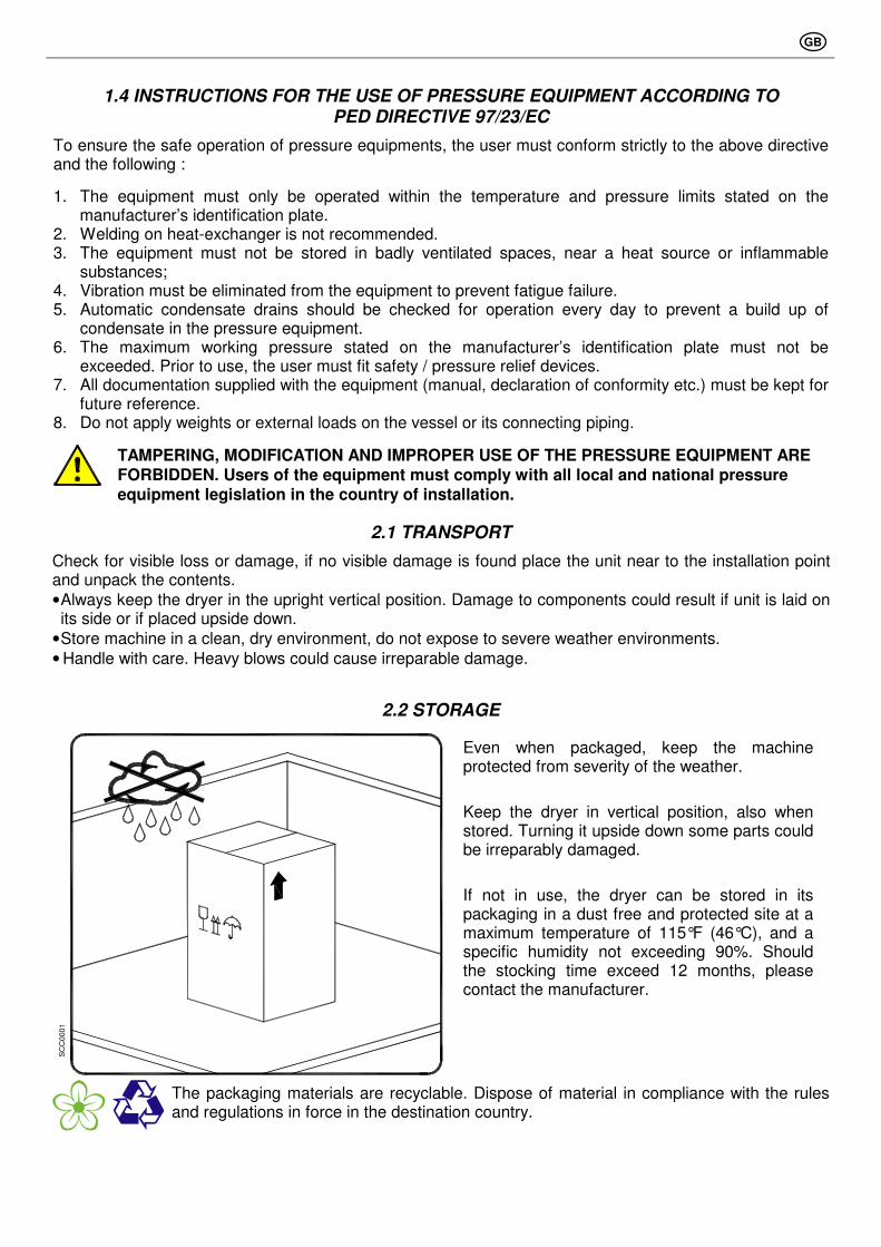
2.3 INSTALLATION SITE
Failure to install dryer in the proper ambient conditions will affect the dryer’s ability to condense refrigerant gas. This can cause higher loads on the compressor, loss of dryer efficiency and performance, overheated condenser fan motors, electrical component failure and dryer failure due to the following: compressor loss, fan motor failure and electrical component failure. Failures of this type will affect warranty considerations. Do not install dryer in an environment of corrosive chemicals, explosive gasses, poisonous gasses; steam heat, areas of high ambient conditions or extreme dust and dirt.
In case of fire, use an approved fire extinguisher, water is not an acceptable means in cases of fire.
Minimum installation requirements:
• Select a clean dry area, free from dust, and protected from atmospheric disturbances.
• The supporting area must be smooth, horizontal and able to hold the weight of the dryer.
• Minimum ambient temperature +34 °F (+1 °C).
• Maximum ambient temperature +115 °F (+46 °C).
• Allow at least a clearance of 40in (1m) on each side of the dryer for proper ventilation and to facilitate eventual maintenance operations.
The dryer does not require attachment to the floor surface; however installations where the unit is suspended require an attachment to the hanging apparatus.
40in - 1m
40
in -
1m
40in - 1m
40in - 1m
20-50
1in
- 2
6m
m
1/2in - 14mm
3/8in - 10mm
14in - 354mm
LG
T0012
1.1
/4in
30
mm
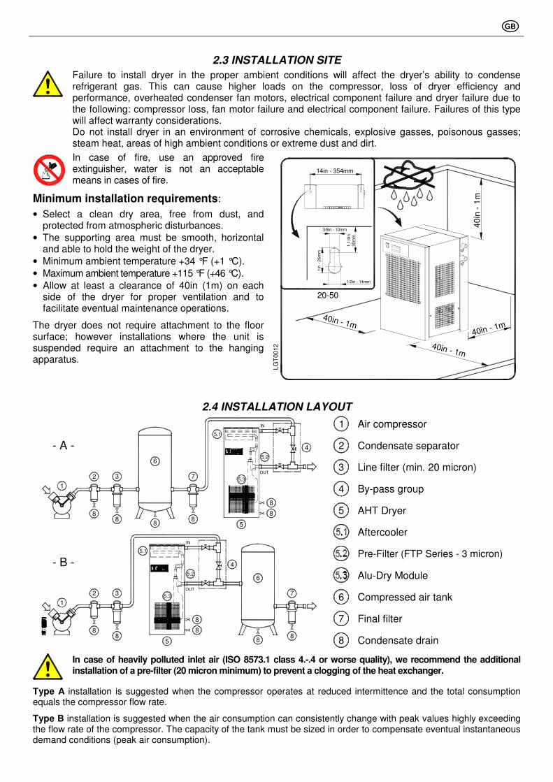
2.4 INSTALLATION LAYOUT
1 Air compressor
2 Condensate separator
3 Line filter (min. 20 micron)
4 By-pass group
5 AHT Dryer
Aftercooler
Pre-Filter (FTP Series - 3 micron)
Alu-Dry Module
6 Compressed air tank
7 Final filter
1
- A -
- B -
2
8
3
8
6
8
8
8
5
5.1
5.2
5.3
IN
OUT
8
7
4
6
8
7
8
2 3
1
88
5
8
8
5.3
OUT
5.2
5.1
IN
4
8 Condensate drain
In case of heavily polluted inlet air (ISO 8573.1 class 4.-.4 or worse quality), we recommend the additional installation of a pre-filter (20 micron minimum) to prevent a clogging of the heat exchanger.
Type A installation is suggested when the compressor operates at reduced intermittence and the total consumption equals the compressor flow rate.
Type B installation is suggested when the air consumption can consistently change with peak values highly exceeding the flow rate of the compressor. The capacity of the tank must be sized in order to compensate eventual instantaneous demand conditions (peak air consumption).
GB
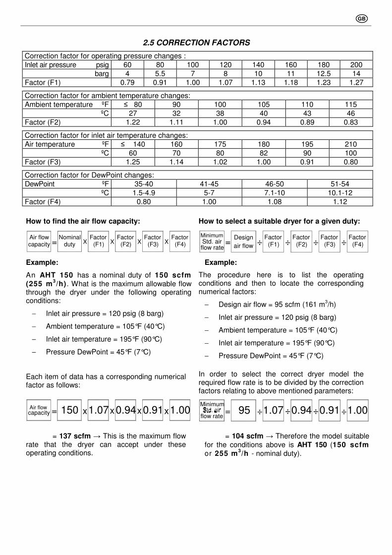
2.5 CORRECTION FACTORS
Correction factor for operating pressure changes :
Inlet air pressure psig 60 80 100 120 140 160 180 200
barg 4 5.5 7 8 10 11 12.5 14
Factor (F1) 0.79 0.91 1.00 1.07 1.13 1.18 1.23 1.27
Correction factor for ambient temperature changes:
Ambient temperature ºF ≤ 80 90 100 105 110 115
ºC 27 32 38 40 43 46
Factor (F2) 1.22 1.11 1.00 0.94 0.89 0.83
Correction factor for inlet air temperature changes:
Air temperature ºF ≤ 140 160 175 180 195 210
ºC 60 70 80 82 90 100
Factor (F3) 1.25 1.14 1.02 1.00 0.91 0.80
Correction factor for DewPoint changes:
DewPoint ºF 35-40 41-45 46-50 51-54
ºC 1.5-4.9 5-7 7.1-10 10.1-12
Factor (F4) 0.80 1.00 1.08 1.12
How to find the air flow capacity: How to select a suitable dryer for a given duty:
Air flowcapacity = X
Factor (F1)
Factor (F2)X
Factor (F3)X X
Factor (F4)
Nominalduty
= ÷
Factor (F1)
Factor (F2)÷
Factor (F3)÷ ÷
Factor (F4)
Design
air flowStd. airflow rate
Minimum
Example: Example:
An AHT 150 has a nominal duty of 150 scfm (255 m
3/h). What is the maximum allowable flow
through the dryer under the following operating conditions:
− Inlet air pressure = 120 psig (8 barg)
− Ambient temperature = 105°F (40°C)
− Inlet air temperature = 195°F (90°C)
− Pressure DewPoint = 45°F (7°C)
Each item of data has a corresponding numerical factor as follows:
The procedure here is to list the operating conditions and then to locate the corresponding numerical factors:
− Design air flow = 95 scfm (161 m3/h)
− Inlet air pressure = 120 psig (8 barg)
− Ambient temperature = 105°F (40°C)
− Inlet air temperature = 195°F (90°C)
− Pressure DewPoint = 45°F (7°C)
In order to select the correct dryer model the required flow rate is to be divided by the correction factors relating to above mentioned parameters:
= 137 scfm → This is the maximum flow rate that the dryer can accept under these operating conditions.
= 104 scfm → Therefore the model suitable for the conditions above is AHT 150 (150 scfm or 255 m
3/h - nominal duty).
= x x x x 1.07 150 0.94 1.00 0.91 capacity Air flow
= ÷ ÷ ÷ ÷ 1.07 95 0.94 1.00 0.91 flow rate
Minimum
GB
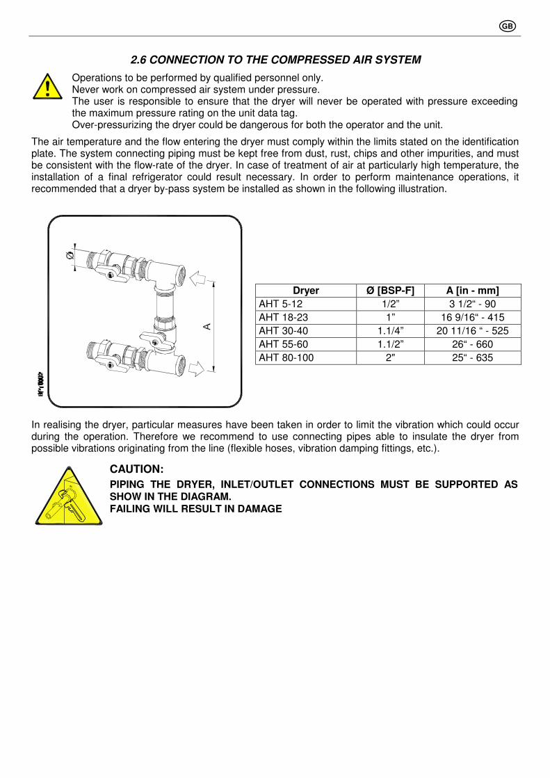
2.6 CONNECTION TO THE COMPRESSED AIR SYSTEM
Operations to be performed by qualified personnel only. Never work on compressed air system under pressure. The user is responsible to ensure that the dryer will never be operated with pressure exceeding the maximum pressure rating on the unit data tag. Over-pressurizing the dryer could be dangerous for both the operator and the unit.
The air temperature and the flow entering the dryer must comply within the limits stated on the identification plate. The system connecting piping must be kept free from dust, rust, chips and other impurities, and must be consistent with the flow-rate of the dryer. In case of treatment of air at particularly high temperature, the installation of a final refrigerator could result necessary. In order to perform maintenance operations, it recommended that a dryer by-pass system be installed as shown in the following illustration.
Dryer Ø [BSP-F] A [in - mm]
AHT 5-12 1/2” 3 1/2“ - 90
AHT 18-23 1” 16 9/16“ - 415
AHT 30-40 1.1/4” 20 11/16 “ - 525
AHT 55-60 1.1/2” 26“ - 660
AHT 80-100 2" 25“ - 635
In realising the dryer, particular measures have been taken in order to limit the vibration which could occur during the operation. Therefore we recommend to use connecting pipes able to insulate the dryer from possible vibrations originating from the line (flexible hoses, vibration damping fittings, etc.).
CAUTION:
PIPING THE DRYER, INLET/OUTLET CONNECTIONS MUST BE SUPPORTED AS SHOW IN THE DIAGRAM. FAILING WILL RESULT IN DAMAGE

GB
2.7 ELECTRICAL CONNECTIONS
Qualified personnel should carry out connecting unit to the main power. Be sure to check the local codes in your area.
Before connecting the unit to the electrical supply, verify the identification plate for the proper electrical information. Voltage tolerance is +/- 5%. Dryer supplied at 115/1/60 voltage comes with a mains connecting cable already installed and ending with a North-American standard plug 2 poles + ground. Dryer supplied at 230/1/60, voltages comes with a box for the connection to the mains. Be sure to provide the proper fuses or breakers based on the data information located on the nameplate.
The mains socket must be provided with a mains magneto-thermal differential breaker (I∆n=0.03A), adjusted on the basis of the consumption of the dryer (see the nominal values on the data plate of the dryer). The cross section of the power supply cables must comply with the consumption of the dryer, while keeping into account also the ambient temperature, the conditions of the mains installation, the length of the cables, and the requirements enforced by the local Power Provider.
Connect to a properly grounded outlet. Improper connection of the equipment-grounding conductor can result in risk of electric shock. Do not use adapters on the main socket- if it does not fit the outlet, have a proper outlet installed by a qualified electrician.
2.8 CONDENSATE DRAIN
The condensate is discharge at the system pressure. Drain line should be secured. Never point the condensate drain line towards anybody.
The dryer comes already fitted with two electronically level controlled BEKOMAT condensate drains. Connect and properly fasten the condensate drain to a collecting plant or container. The drain cannot be connected to pressurized systems.
Don’t dispose the condensate in the environment. The condensate collected in the dryer contains oil particles released in the air by the compressor. Dispose the condensate in compliance with the local rules. We suggest to install a water-oil separator where to convey all the condensate drain coming from compressors, dryers, tanks, filters, etc.
3.1 PRELIMINARY OPERATION
Verify that the operating parameters match with the nominal values stated on the identification plate of the dryer (voltage, frequency, air pressure, air temperature, ambient temperature, etc.).
This dryer has been thoroughly tested, packaged and inspected prior to shipment. Nevertheless, the unit could be damaged during transportation, check the integrity of the dryer during first start-up and monitor operation during the first hours of operation.
Qualified personnel must perform the first start-up. When installing and operating this equipment, comply with all National Electrical Code and any applicable federal, state and local codes. Who is operating the unit is responsible for the proper and safe operation of the dryer. Never operate equipment with panels removed.

GB
3.2 FIRST START-UP
This procedure should be followed on first start-up, after periods of extended shutdown or following maintenance procedures. Qualified personnel must perform the start-up.
Sequence of operations (refer to paragraph 5.1 Control Panel) :
• Ensure that all the steps of the “Installation” chapter have been observed.
• Ensure that the connection to the compressed air system is correct and that the piping is suitably fixed and supported.
• Ensure that the condensate drain pipe is properly fastened and connected to a collection system or container.
• Ensure that the by-pass system (if installed) is open and the dryer is isolated
• Ensure that the manual valve of the condensate drain circuit is open.
• Remove any packaging and other material which could obstruct the area around the dryer.
• Activate the mains switch.
• Switch on the dryer by closing the main switch on the control panel (pos. 1).
• Ensure that DMC14 electronic instrument is ON.
• Ensure the consumption matches with the values of the data plate.
• Ensure the fan work properly - wait for its first interventions.
• Allow the dryer temperature to stabilise at the pre-set value.
• Slowly open the air inlet valve.
• Slowly open the air outlet valve.
• Slowly close the central by-pass valve of the system (if installed).
• Check the piping for air leakage.
• Ensure the drain is regularly cycling - wait for its first interventions.
3.3 START-UP AND SHUT DOWN
Start-up (refer to paragraph 5.1 Control Panel) :
• Check the condenser for cleanliness.
• Verify that the system is powered.
• Switch on the dryer by closing the main switch on the control panel (pos. 1).
• Ensure that DMC14 electronic instrument is ON.
• Wait a few minutes; verify that the DewPoint temperature displayed on electronic instrument DMC14 is correct and that the condensate is regularly drained.
• Switch on the air compressor.
Shut down (refer to paragraph 5.1 Control Panel) :
• Verify that the DewPoint temperature displayed on electronic controller DMC14 is correct.
• Shut down the air compressor.
• After a few minutes, Shut down the dryer using the main switch on the control panel (pos. 1).
NOTE : A DewPoint within 32°F (0°C) and +60°F (15°C) displayed on DMC14 is correct according to the possible working conditions (flow-rate, temperature of the incoming air, ambient temperature, etc.).
During the operation, the refrigerating compressor will run continuously. The dryer must remain on during the full usage period of the compressed air, even if the air compressor works intermittently.
The number of starts must be no more than 6 per hour. The dryer must stop running for at least 5 minutes before being started up again. The user is responsible for compliance with these rules. Frequent starts may cause irreparable damage.
GB
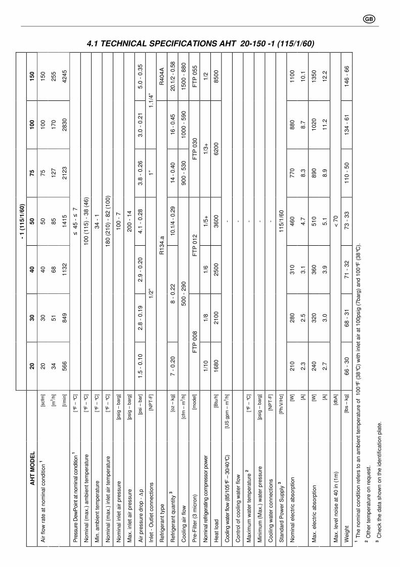
4.1 TECHNICAL SPECIFICATIONS AHT 20-150 -1 (115/1/60)
15
0
15
0
25
5
42
45
5.0
- 0
.35
R4
04
A
20.1
/2 - 0
.58
15
00
- 8
80
FT
P 0
55
1/2
85
00
11
00
10
.1
13
50
12
.2
14
6 -
66
10
0
10
0
17
0
28
30
3.0
- 0
.21
1.1
/4”
16 - 0
.45
10
00
- 5
90
88
0
8.7
10
20
11
.2
13
4 -
61
75
75
12
7
21
23
3.8
- 0
.26
1”
14 - 0
.40
90
0 -
53
0 F
TP
03
0
1/3
+
62
00
77
0
8.3
89
0
8.9
11
0 -
50
50
50
85
14
15
4.1
- 0
.28
10.1
/4 - 0
.29
1/5
+
36
00
46
0
4.7
51
0
5.1
73
- 3
3
40
40
68
11
32
2.9
- 0
.20
FT
P 0
12
1/6
25
00
31
0
3.1
36
0
3.9
71
- 3
2
30
30
51
84
9
2.8
- 0
.19
8 -
0.2
2
1/8
21
00
28
0
2.5
32
0
3.0
68
- 3
1
- 1
(1
15
/1/6
0)
20
20
34
56
6
≤
45
- ≤
7
10
0 (
11
5)
- 3
8 (
46
)
34
- 1
18
0 (
21
0)
- 8
2 (
10
0)
10
0 -
7
20
0 -
14
1.5
- 0
.10
1/2
”
R1
34
.a
7 -
0.2
0
50
0 -
29
0
FT
P 0
08
1/1
0
16
80
- - - - -
11
5/1
/60
21
0
2.3
24
0
2.7
< 7
0
66
- 3
0
[scfm
]
[m3/h
]
[l/m
in]
[°F
– °
C]
[°F
– °
C]
[°F
– °
C]
[°F
– °
C]
[psig
– b
arg
]
[psig
– b
arg
]
[psi – b
ar]
[NP
T-F
]
[oz –
kg]
[cfm
– m
3/h
]
[model]
[Btu
/h]
[US
gpm
– m
3/h
]
[°F
– °
C]
[psig
– b
arg
]
[NP
T-F
]
[Ph/V
/Hz]
[W]
[A]
[W]
[A]
[dbA
]
[lbs –
kg]
AH
T M
OD
EL
Air f
low
rate
at
nom
inal conditio
n 1
Pre
ssure
Dew
Poin
t at n
om
inal c
onditi
on 1
Nom
inal (m
ax.)
am
bie
nt
tem
pera
ture
Min
. am
bie
nt
tem
pera
ture
Nom
inal (m
ax.)
inle
t air t
em
pera
ture
Nom
inal in
let
air p
ressure
Max.
inle
t air p
ressure
Air p
ressure
dro
p -
∆p
Inle
t -
Outlet
connections
Refr
igera
nt
type
Refr
igera
nt
quantity
3
Coolin
g a
ir f
low
Pre
-Filt
er
(3 m
icro
n)
Nom
inal r
efrig
era
ting c
om
pre
ssor pow
er
Heat
load
Coolin
g w
ate
r flo
w (85/1
05°F
– 3
0/4
0°C
)
Contr
ol of
coolin
g w
ate
r flow
Maxim
um
wate
r te
mpera
ture
2
Min
imum
(M
ax.)
wate
r pre
ssure
Coolin
g w
ate
r connections
Sta
ndard
Pow
er
Supply
3
Nom
inal ele
ctr
ic a
bsorp
tion
Max.
ele
ctr
ic a
bsorp
tion
Max.
level nois
e a
t 40 in (
1m
)
Weig
ht
1 T
he n
om
inal conditio
n r
efe
rs t
o a
n a
mbie
nt
tem
pera
ture
of
100°F
(38°C
) w
ith inle
t air a
t 100psig
(7barg
) and 1
00°F
(38°C
).
2 O
ther
tem
pera
ture
on r
equest.
3 C
heck t
he d
ata
show
n o
n t
he identification p
late
.

GB
4.2 TECHNICAL SPECIFICATIONS AHT 20-350 -2 (230/1/60)
35
0
35
0
59
4
99
05
4.5
- 0
.31
42 –
1.2
0
6350 - 3
700
FT
P 1
20
23
00
11
.1
26
90
12
.8
30
4 -
13
8
30
0
30
0
50
9
84
90
4.1
- 0
.28 2
”
35 –
1.0
0
6150 - 3
600 1.1
/4
20
40
0
22
00
10
.5
25
80
12
.3
29
1 -
1
32
25
0
25
0
42
5
70
75
5.1
- 0
.35
33.1
/2 - 0
.95
5000 - 2
900
1.1
/8 FT
P 0
80
17
50
0
18
20
8.1
22
80
10
.4
18
5 -
84
20
0
20
0
34
0
56
60
3.3
- 0
.23
1.1
/2”
30.1
/2 - 0
.87
3500 - 2
060
5/8
11
90
0
15
50
7.0
16
50
7.3
16
5 -
75
15
0
15
0
25
5
42
45
5.0
-0.3
5
R4
04
A
20.1
/2- 0.5
8
1500 - 8
80
1/2
FT
P 0
55
85
00
11
00
5.1
13
50
6.1
14
6 -
66
10
0
10
0
17
0
28
30
3.0
- 0
.21
1.1
/4”
16 - 0
.45
1000 - 5
90
88
0
4.3
10
20
5.6
13
4 -
61
75
75
12
7
21
23
3.8
- 0
.26
1”
14 - 0
.40
900 - 5
30 1
/3+
FT
P 0
30
62
00
77
0
4.2
89
0
4.5
11
0 -
50
50
50
85
14
15
4.1
- 0
.28
10.1
/4 –
0.2
9
1/4
40
00
46
0
2.3
51
0
2.5
73
- 3
3
40
40
68
11
32
2.9
- 0
.20
FT
P 0
12
31
0
1.6
36
0
1.9
71
- 3
2
30
30
51
84
9
2.8
- 0
.19
8 - 0
.22
1/6
25
00
28
0
1.3
32
0
1.5
68
- 3
1
- 2
(2
30
/1/6
0)
20
20
34
56
6
≤
45
- ≤
7
10
0 (
11
5)
- 3
8 (
46
)
34
- 1
18
0 (
21
0)
- 8
2 (
10
0)
10
0 -
7
20
0 -
14
1.5
- 0
.10
1/2
”
R1
34
.a
7- 0.2
0
500 - 2
90
1/1
0 FT
P 0
08
16
80
- - - - -
23
0/1
/60
21
0
1.1
24
0
1.4
< 7
0
66
- 3
0
[scf
m]
[m3 /h
]
[l/m
in]
[°F –
°C
]
[°F –
°C
]
[°F –
°C
]
[°F –
°C
]
[psi
g –
barg
]
[psi
g –
barg
]
[psi
– b
ar]
[NP
T-F
]
[oz
– k
g]
[cfm
– m
3 /h]
[model]
[Btu
/h]
[US
gpm
–
m3 /h
]
[°F –
°C
]
[psi
g –
barg
]
[NP
T-F
]
[Ph/V
/Hz]
[W]
[A]
[W]
[A]
[dbA
]
[lbs
– k
g]
AH
T M
OD
EL
Air f
low
rate
at
nom
inal conditio
n 1
Pre
ssure
Dew
Poin
t at n
om
inal c
onditi
on 1
Nom
inal (m
ax.)
am
bie
nt
tem
pera
ture
Min
. am
bie
nt
tem
pera
ture
Nom
inal (m
ax.)
inle
t air t
em
pera
ture
Nom
inal in
let
air p
ressure
Max.
inle
t air p
ressure
Air p
ressure
dro
p -
∆p
Inle
t -
Outlet
connections
Refr
igera
nt
type
Refrig
era
nt q
uantit
y 3
Coolin
g a
ir flo
w
Nom
inal r
efrig
era
ting c
om
pre
ssor pow
er
Pre
-Filt
er
(3 m
icro
n)
Heat
load
Coolin
g w
ate
r flo
w (85/1
05°F
– 3
0/4
0°C
)
Contr
ol of
coolin
g w
ate
r flow
Maxim
um
wate
r te
mpera
ture
2
Min
imum
(M
ax.)
wate
r pre
ssure
Coolin
g w
ate
r connections
Sta
ndard
Pow
er
Supply
3
Nom
inal ele
ctr
ic a
bsorp
tion
Max.
ele
ctr
ic a
bsorp
tion
Max.
level nois
e a
t 40 in (
1m
)
Weig
ht
1 T
he n
om
inal conditio
n r
efe
rs t
o a
n a
mbie
nt
tem
pera
ture
of
100°F
(38°C
) w
ith inle
t air a
t 100psig
(7barg
) and 1
00°F
(38°C
).
2 O
ther
tem
pera
ture
on r
equest.
3 C
heck t
he d
ata
show
n o
n t
he identification p
late
.

GB
5.1 CONTROL PANEL
The control panel illustrated below is the only dryer-operator interface.
AHT 20 - 75
K
1
2 3
PQ
S0
00
3
DMC141
0
AHT 100 - 350
KION
1 3
set
DMC 14°C
esc
°F
2
PQ
S00
04
1 Main switch 3 Air and refrigerating gas flow diagram
2 Electronic control instrument DMC14
5.2 OPERATION
Operating principal – The dryer models described in this manual all operate on the same principal. First the very hot moisture laden air directly from the compressor enters the aftercooler (copper tube / aluminum fin cooling surface) where it is cooled to within 18-20°F (10-12°C) of the ambient air temperature. It leaves the aftercooler with entrained condensed water droplets which are separated by the 3 micron FTP bulk liquid filter separator element and drained away by the first drain system. The partially cooled moisture laden air next enters an air to air heat exchanger to pre-cool it. The compressed air next goes through the evaporator, also known as the air to refrigerant heat exchanger. The compressed air temperature is reduced to approximately 41°F (5°C), causing additional water vapor to condense to liquid. The liquid is continuously coalesced and collected in the dryer separator for automatic removal by the second condensate drain. The cool moisture free compressed air then passes back through the air to air heat exchanger to be reheated to within the ambient temperature as it exits the dryer.
Refrigerant circuit - Refrigerant gas is cycled through the compressor and exits at high pressure to a condenser where heat is removed causing the refrigerant to condense to a high-pressure liquid state. The liquid is forced through a capillary tube where the resulting pressure drop allows the refrigerant to boil off at a predetermined temperature. Low-pressure liquid refrigerant enters the heat exchanger where heat from the incoming air is transferred causing the refrigerant to boil; the resulting phase change produces a low pressure, low temperature gas. The low-pressure gas is returned to the compressor, where it is re-compressed and begins the cycle again. During those periods when the compressed air load is reduced the excess refrigerant is by-passed automatically back to the compressor via the Hot Gas By-pass Valve circuit.

GB
5.3 FLOW DIAGRAM (Air-Cooled)
13
1
12
1c
T1
1b
1a
PB
3 54
P
11 10
7
6
TS
9 M
8
PVA
2
DG
F0035 21
28
27
21
26
1 Alu-Dry Module 9 Condenser fan
a - Air-to-air heat exchanger 10 Filter Drier
b - Air-to-refrigerant exchanger 11 Capillary tube
c - Condensate separator 12 T1 Temperature probe (DewPoint)
2 Refrigerant pressure-switch PB (AHT 300-350) 13 Condensate drain isolation valve
3 Safety thermo-switch TS (AHT 125-350) …
4 Refrigerant pressure-switch PA (AHT 300-350) 21 Bekomat drainer
5 Refrigerant Fan pressure-switch PV …
6 Refrigerating compressor 26 Aftercooler
7 Hot Gas By-pass Valve 27 Aftercooler fan (AHT 75-350)
8 Condenser (Air-Cooled) 28 Pre-Filter (3 micron)
Compressed air flow direction Refrigerating gas flow direction
5.4 REFRIGERATING COMPRESSOR
The refrigerating compressor is the pump in the system, gas coming from the evaporator (low pressure side) is compressed up to the condensation pressure (high pressure side). The compressors utilized are manufactured by leading manufacturers and are designed for applications where high compression ratios and wide temperature changes are present.
The hermetically sealed construction is perfectly gas tight, ensuring high-energy efficiency and long, useful life. Dumping springs support the pumping unit in order to reduce the acoustic emission and the vibration diffusion. The aspirated refrigerating gas, flowing through the coils before reaching the compression cylinders cools the electric motor. The thermal protection protects the compressor from over heating and over currents. The protection is automatically restored as soon as the nominal temperature conditions are reached.

GB
5.5 CONDENSER
The condenser is the component in which the gas coming from the compressor is cooled down and condensed becoming a liquid. Mechanically, a serpentine copper tubing circuit (with the gas flowing inside) is encapsulated in an aluminum fin package. The cooling operation occurs via a high efficiency fan, creating airflow within the dryer, moving air through the fin package. It’s mandatory that the ambient air temperature does not exceed the nominal values. It is also important TO KEEP THE CONDENSER UNIT FREE FROM DUST AND OTHER IMPURITIES
5.6 FILTER DRIER
Traces of humidity and slag can accumulate inside the refrigerating circuit. Long periods of use can also produce sludge. This can limit the lubrication efficiency of the compressor and clog the expansion valve or capillary tube. The function of the Filter Drier, located before the capillary tubing, is to eliminate any impurities from circulating through the system.
5.7 AFTERCOOLER
The aftercooler is the element where the incoming hot air undergoes the cooling stage. Mechanically, it is formed by a copper tubing circuit (with the compressed air flowing inside) immersed in an aluminium blades package. The cooling operation occurs via a high efficiency axial ventilator which, in applying pressure on the air contained within the dryer, forces it into the blades package. In models AHT 20-50 the aftercooler is combined with the dryer’s condenser, thus forming just one heat exchanger battery, cooled by just one high efficiency axial fan. It is mandatory that the temperature of the ambient air will not exceed the nominal values of the dryer. It is important TO KEEP THE UNIT FREE FROM DUST AND OTHER IMPURITIES taken in by the fan.
5.8 PRE-FILTER (FTP Series - 3 micron)
Positioned at the outlet of the aftercooler, it assures a good air cleanliness level, in addition to the complete removal of the water condensed in the aftercooler. REPLACE THE FILTERING ELEMENT (CARTRIDGE) AT LEAST EVERY 12 MONTHS.
5.9 CAPILLARY TUBE
It consists of a piece of reduced cross section copper tubing located between the condenser and the evaporator to form a throttling against the flow of the refrigerating fluid. This throttling creates a pressure drop, which is a function of the temperature to be reached within the evaporator: the lower the capillary tube outlet pressure, the lower the evaporation temperature. The length and the diameter of the capillary tubing are accurately sized with the performance to be reached by the dryer; no maintenance/adjustment operations are necessary.
5.10 ALU-DRY MODULE
The air-to-air and the air-to-refrigerant heat exchangers plus the demister type condensate separator are housed in a unique module. The counter-flows of compressed air in the air-to-air heat exchanger ensure maximum heat transfer. The large cross section of flow channels within the heat exchanger module leads to low velocities and reduced power requirements. The air-to-refrigerant exchanger, with counter-current flows, assure excellent performances. The generous dimensions of the exchange surface determines the correct and complete evaporation of the refrigerant (preventing liquid returning to the compressor). The high efficiency condensate separator is located within the drying module. No maintenance is required and it offers the additional advantage of creating a cold coalescing effect for excellent air drying results. The generous collection volume assures the correct operation of the dryer even with extremely damp inlet air.

GB
5.11 HOT GAS BY-PASS VALVE
This valve injects part of the hot gas (taken from the discharge side of the compressor) in the pipe between the evaporator and the suction side of the compressor, keeping the evaporation temperature/pressure constant at approx. 36°F (+2 °C). This injection prevents the formation of ice inside the dryer evaporator at every load condition.
A
4 mm5/32 in.
+
-
ADJUSTMENT The hot gas by-pass valve is adjusted during the manufacturing testing phase. As a rule no adjustment is required; anyway if it is necessary the operation must be carried out by an experienced refrigeration engineer.
WARNING : the use of ¼” Schrader service valves must be justified by a real malfunction of the refrigeration system. Each time a pressure gauge is connected, a part of refrigerant is exhausted. Without compressed air flow through the dryer, rotate the adjusting screw (position A on the drawing) until the following value is reached: Hot gas setting (R134.a) : temperature 33°F (+1 / -0 °F)
pressure 29 psig (+1.5 / -0 psi) temperature 0.5°C (+0.5 / -0 °K)
pressure 2.0 barg (+0.1 / -0 bar) Hot gas setting (R404A) : temperature 33°F (+1 / -0 °F)
pressure 75.4 psig (+1.5 / -0 psi) temperature 0.5 °C (+0.5 / -0 °K)
pressure 5.2 barg (+0.1 / -0 bar)
5.12 REFRIGERANT PRESSURE SWITCHES PA - PB - PV
As operation safety and protection of the dryer a series of pressure switches are installed in gas circuit.
PB : Low-pressure controller device on the pushing side (carter) of the compressor, is enabled only if the pressure drops below the pre-set value. The values are automatically reset when the nominal conditions are restored.
Calibrated pressure : R 404 A Stop 14.5 psig - Restart 72.5 psig
R 404 A Stop 1.0 barg - Restart 5.0 barg
PA : This high-pressure controller device, located on the pushing side on the compressor, is activated when the pressure exceeds the pre-set value. It features a manual-resetting button mounted on the controller itself.
Calibrated pressure : R 404 A Stop 464 psig - Manual reset
R 404 A Stop 32 barg - Manual reset
PV : Fan control pressure switch is placed at the discharge side of refrigeration compressor. It keeps the condensation temperature/pressure constant within preset limits (Air-Cooled).
Calibrated pressure : R 134.a Start 160 psig (117°F) - Stop 116 psig (97°F) - Tolerance ± 15 psi
R 134.a Start 11 barg (47°C) - Stop 8 barg (36°C) - Tolerance ± 1 bar
R 404 A Start 290 psig (113°F) - Stop 232 psig (97°F) - Tolerance ± 15 psi
R 404 A Start 20 barg (45°C) - Stop 16 barg (36°C) - Tolerance ± 1 bar
5.13 SAFETY THERMO-SWITCH TS
To protect the operating safety and the integrity of the dryer, a thermo-switch (TS) is installed on the refrigerant gas circuit. The thermo-switch sensor, in case of unusual discharge temperatures, stops the refrigerating compressor before it is permanently damaged.
1
2
PQ
S0
00
5
TS : Manually reset the thermo-switch only after the nominal operating conditions have been restored. Unscrew the relative cap (see pos.1 in the figure) and press the reset button (see pos.2 in the figure).

GB
5.14 DMC14 ELECTRONIC INSTRUMENT (AIR DRYER CONTROLLER)
set Button - access the set-up.
esc Button - Exit programming / decrease value.
Button - Value increment.
LED - Dryer in alarm status.
● °C LED - Display the set temperature scale (°C).
● °F LED - Display the set temperature scale (°F).
DMC 14°C
°F
escset
DISPLAY
PQ
S0
00
6
● LED - Not used
Through the digital thermometer with an alphanumerical display, the DMC14 controller shows the DewPoint detected by the probe in the evaporator.
The LED shows any alarm condition, it can happen when : - pressure DewPoint is too high; - pressure DewPoint is too low; - the probe is faulty.
If the probe is faulty, the instrument also shows “PF” message (Probe Failure), and alarm activation is immediate. In case of “DewPoint too low” condition (ASL parameter, that is fix and equal to 28.5°F or -2°C), the alarm signal is delayed of a fix time (AdL parameter) equal to 30 sec, while for “DewPoint too high” condition the value (ASH parameter) is set by the user and the signal is activated with AdH delay time, that can be also set up by the operator (the instrument is already adjusted during final test of the dryer, please see following values). When DewPoint returns into operating temperature (set range), the alarm condition is deactivated.
DMC14 allows also remote annunciation of the alarm condition of the dryer; this through a volt free contact on terminals 8 & 9 - please also see electric drawings into the attachments (max 250V 1A, min 5VDC 10mA) - with dryer off or in alarm conditions contact is open - with dryer on and correct operating DewPoint, contact is closed.
OPERATION - After dryer starting, the electronic controller displays current operating DewPoint : it shows the measured temperature in Celsius degrees (● °C) with a 0.5°C resolution, or in Fahrenheit degrees (● °F) with a 1°F resolution.
SET-UP (PROGRAMMING)
To access the set-up, keep pressed simultaneously both set and button for at least 5 seconds. In this way programming operation will be activated and the controller display shows the first parameter
that can be set (Ton). After that, by pressing set buttom the display shows the value set for that parameter.
If the value is correct press set button to conferm it and to give access on following parameters. To
change the value of selected parameter, must be used esc and button, respectively to decrease or increase the value. All parameters that can be modified are indicated in following table :
Display Description Value range Set value Equal to
Ton Not used 01 … 20 02 2 sec
ToF Not used 01 … 20 01 1 min
ASH Alarm threshold for a high DewPoint . 0.0 … 68.0 60 60°F
AdH ASH alarm time before signal 00 … 20 20 20 min
SCL Temperature scale °C … °F °F °Fahrenheit
Fixed parameters : ASL (low DewPoint alarm) = -2°C or 28.5°F AdL (signal delay) = 30 sec
It is possibile to exit from set-up conditon in any moment, by pressing simultaneously both esc and button. If any operations are not made during 30 seconds, the controller exits automatically from programming operation.
GB
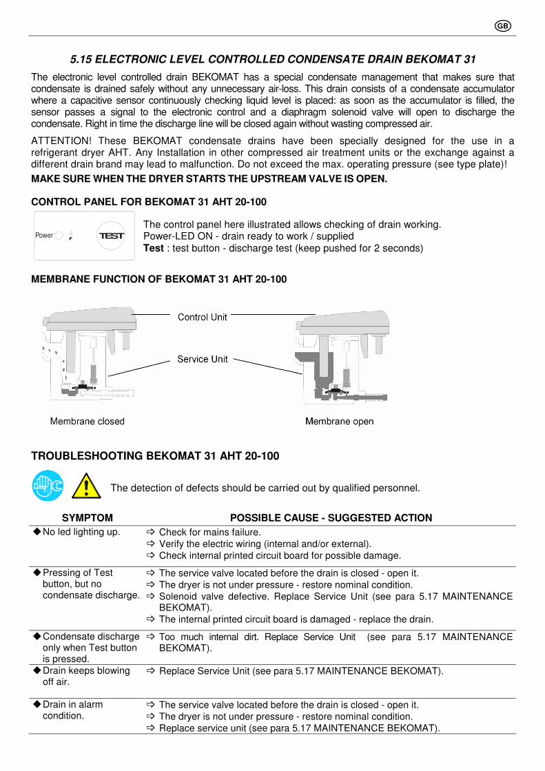
5.15 ELECTRONIC LEVEL CONTROLLED CONDENSATE DRAIN BEKOMAT 31
The electronic level controlled drain BEKOMAT has a special condensate management that makes sure that condensate is drained safely without any unnecessary air-loss. This drain consists of a condensate accumulator where a capacitive sensor continuously checking liquid level is placed: as soon as the accumulator is filled, the sensor passes a signal to the electronic control and a diaphragm solenoid valve will open to discharge the condensate. Right in time the discharge line will be closed again without wasting compressed air.
ATTENTION! These BEKOMAT condensate drains have been specially designed for the use in a refrigerant dryer AHT. Any Installation in other compressed air treatment units or the exchange against a different drain brand may lead to malfunction. Do not exceed the max. operating pressure (see type plate)!
MAKE SURE WHEN THE DRYER STARTS THE UPSTREAM VALVE IS OPEN.
CONTROL PANEL FOR BEKOMAT 31 AHT 20-100
TESTPower
The control panel here illustrated allows checking of drain working. Power-LED ON - drain ready to work / supplied Test : test button - discharge test (keep pushed for 2 seconds)
MEMBRANE FUNCTION OF BEKOMAT 31 AHT 20-100
TROUBLESHOOTING BEKOMAT 31 AHT 20-100
The detection of defects should be carried out by qualified personnel.
SYMPTOM POSSIBLE CAUSE - SUGGESTED ACTION
� No led lighting up. � Check for mains failure.
� Verify the electric wiring (internal and/or external).
� Check internal printed circuit board for possible damage.
� Pressing of Test button, but no condensate discharge.
� The service valve located before the drain is closed - open it. � The dryer is not under pressure - restore nominal condition. � Solenoid valve defective. Replace Service Unit (see para 5.17 MAINTENANCE
BEKOMAT). � The internal printed circuit board is damaged - replace the drain.
� Condensate discharge only when Test button is pressed.
� Too much internal dirt. Replace Service Unit (see para 5.17 MAINTENANCE BEKOMAT).
� Drain keeps blowing off air.
� Replace Service Unit (see para 5.17 MAINTENANCE BEKOMAT).
� Drain in alarm condition.
� The service valve located before the drain is closed - open it. � The dryer is not under pressure - restore nominal condition. � Replace service unit (see para 5.17 MAINTENANCE BEKOMAT).

GB
5.16 ELECTRONIC LEVEL CONTROLLED CONDENSATE DRAIN BEKOMAT 32
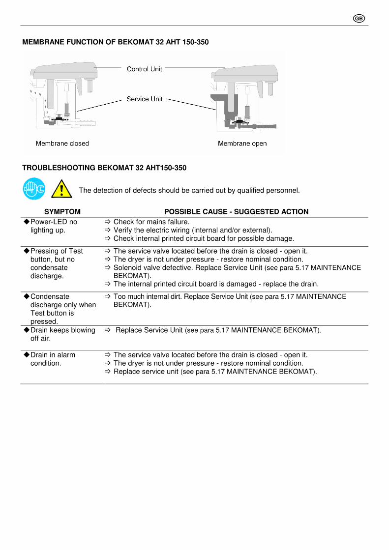
The electronic level controlled drain BEKOMAT has a special condensate management that makes sure that condensate is drained safely without any unnecessary air-loss. This drain consists of a condensate accumulator where a capacitive sensor continuously checking liquid level is placed: as soon as the accumulator is filled, the sensor passes a signal to the electronic control and a diaphragm solenoid valve will open to discharge the condensate. Right in time the discharge line will be closed again without wasting compressed air.
ATTENTION! These BEKOMAT condensate drains have been specially designed for the use in a refrigerant dryer AHT. Any installation in other compressed air treatment units or the exchange against a different drain brand may lead to malfunction. Do not exceed the max. operating pressure (see type plate)!
MAKE SURE WHEN THE DRYER STARTS THE UPSTREAM VALVE IS OPEN.
CONTROL PANEL FOR BEKOMAT 32 AHT 150-350
The control panel here illustrated allows checking of drain working. Power-LED ON - drain ready to work / supplied Test : test button - discharge test (keep pushed for 2 seconds)
Malfunction/Alarm
Test : button - discharge test (keep pushed for 2 seconds)
The BEKOMAT 32 also has an alarm mode function: If normal conditions have not been restored after 1 minute, a fault signal will be triggered: • Alarm LED flashes. • Alarm signal switches over (can be transmitted via potential-free contact terminals 2.2, 2.3, 2.4). • Valve opens every 4 minutes for a period of 7.5 seconds. Once the fault is cleared, the BEKOMAT will automatically switch back to the normal mode of operation.
GB
MEMBRANE FUNCTION OF BEKOMAT 32 AHT 150-350
TROUBLESHOOTING BEKOMAT 32 AHT150-350
The detection of defects should be carried out by qualified personnel.
SYMPTOM POSSIBLE CAUSE - SUGGESTED ACTION
� Power-LED no lighting up.
� Check for mains failure. � Verify the electric wiring (internal and/or external). � Check internal printed circuit board for possible damage.
� Pressing of Test button, but no condensate discharge.
� The service valve located before the drain is closed - open it. � The dryer is not under pressure - restore nominal condition. � Solenoid valve defective. Replace Service Unit (see para 5.17 MAINTENANCE
BEKOMAT). � The internal printed circuit board is damaged - replace the drain.
� Condensate discharge only when Test button is pressed.
� Too much internal dirt. Replace Service Unit (see para 5.17 MAINTENANCE BEKOMAT).
� Drain keeps blowing off air.
� Replace Service Unit (see para 5.17 MAINTENANCE BEKOMAT).
� Drain in alarm condition.
� The service valve located before the drain is closed - open it. � The dryer is not under pressure - restore nominal condition. � Replace service unit (see para 5.17 MAINTENANCE BEKOMAT).
GB
5.17 MAINTENANCE BEKOMAT
Only qualified personnel should perform troubleshooting and or maintenance operations. Prior to performing any maintenance or service, be sure that:
• no part of the machine is powered and that it cannot be connected to the mains supply.
• no part of the machine is under pressure and that it cannot be connected to the compressed air system.
• Maintenance personnel have read and understand the safety and operation instructions in this manual.
Recommended maintenance: 1 x per year
ATTENTION! Before maintenance or repair, make sure the BEKOMAT is not pressurised.
ATTENTION! Before installation, maintenance or repair, make sure the BEKOMAT is in a powerless state. Before work, disconnect from power supply.
MAINTENANCE BEKOMAT
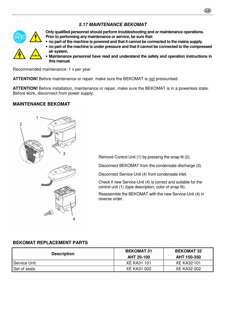
Remove Control Unit (1) by pressing the snap-fit (2).
Disconnect BEKOMAT from the condensate discharge (3).
Disconnect Service-Unit (4) from condensate inlet.
Check if new Service-Unit (4) is correct and suitable for the control unit (1) (type description, color of snap-fit).
Reassemble the BEKOMAT with the new Service-Unit (4) in reverse order.
BEKOMAT REPLACEMENT PARTS
BEKOMAT 31 BEKOMAT 32 Description
AHT 20-100 AHT 150-350
Service Unit XE KA31 101 XE KA32 101
Set of seals XE KA31 002 XE KA32 002
GB
6.1 CONTROLS AND MAINTENANCE
Only qualified personnel should perform troubleshooting and or maintenance operations. Prior to performing any maintenance or service, be sure that:
• no part of the machine is powered and that it cannot be connected to the mains supply.
• no part of the machine is under pressure and that it cannot be connected to the compressed air system.
• Maintenance personnel have read and understand the safety and operation instructions in this manual.
Before attempting any maintenance operation on the dryer, shut it down and wait at least 30 minutes. Some components can reach high temperature during operation. Avoid contact until system or component has dissipated heat.
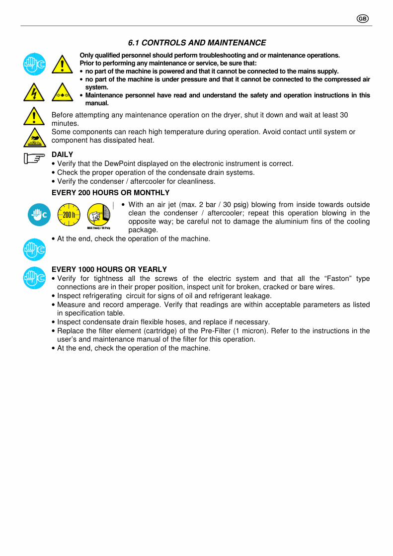
DAILY
• Verify that the DewPoint displayed on the electronic instrument is correct.
• Check the proper operation of the condensate drain systems.
• Verify the condenser / aftercooler for cleanliness.
EVERY 200 HOURS OR MONTHLY
• With an air jet (max. 2 bar / 30 psig) blowing from inside towards outside clean the condenser / aftercooler; repeat this operation blowing in the opposite way; be careful not to damage the aluminium fins of the cooling package.
• At the end, check the operation of the machine.
EVERY 1000 HOURS OR YEARLY
• Verify for tightness all the screws of the electric system and that all the “Faston” type connections are in their proper position, inspect unit for broken, cracked or bare wires.
• Inspect refrigerating circuit for signs of oil and refrigerant leakage.
• Measure and record amperage. Verify that readings are within acceptable parameters as listed in specification table.
• Inspect condensate drain flexible hoses, and replace if necessary.
• Replace the filter element (cartridge) of the Pre-Filter (1 micron). Refer to the instructions in the user’s and maintenance manual of the filter for this operation.
• At the end, check the operation of the machine.
GB
6.2 TROUBLESHOOTING
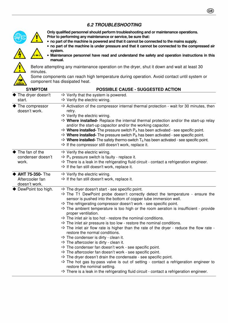
Only qualified personnel should perform troubleshooting and or maintenance operations. Prior to performing any maintenance or service, be sure that:
• no part of the machine is powered and that it cannot be connected to the mains supply.
• no part of the machine is under pressure and that it cannot be connected to the compressed air system.
• Maintenance personnel have read and understand the safety and operation instructions in this manual.
Before attempting any maintenance operation on the dryer, shut it down and wait at least 30 minutes. Some components can reach high temperature during operation. Avoid contact until system or component has dissipated heat.
SYMPTOM POSSIBLE CAUSE - SUGGESTED ACTION
� The dryer doesn't start.
� Verify that the system is powered.
� Verify the electric wiring.
� The compressor doesn’t work.
� Activation of the compressor internal thermal protection - wait for 30 minutes, then retry.
� Verify the electric wiring.
� Where installed- Replace the internal thermal protection and/or the start-up relay and/or the start-up capacitor and/or the working capacitor.
� Where installed- The pressure switch PA has been activated - see specific point.
� Where installed- The pressure switch PB has been activated - see specific point.
� Where installed- The safety thermo-switch TS has been activated - see specific point.
� If the compressor still doesn’t work, replace it.
� The fan of the condenser doesn’t work.
� Verify the electric wiring.
� PV pressure switch is faulty - replace it.
� There is a leak in the refrigerating fluid circuit - contact a refrigeration engineer.
� If the fan still doesn't work, replace it.
� AHT 75-350- The Aftercooler fan doesn’t work.
� Verify the electric wiring.
� If the fan still doesn't work, replace it.
� DewPoint too high. � The dryer doesn't start - see specific point.
� The T1 DewPoint probe doesn’t correctly detect the temperature - ensure the sensor is pushed into the bottom of copper tube immersion well.
� The refrigerating compressor doesn’t work - see specific point.
� The ambient temperature is too high or the room aeration is insufficient - provide proper ventilation.
� The inlet air is too hot - restore the nominal conditions.
� The inlet air pressure is too low - restore the nominal conditions.
� The inlet air flow rate is higher than the rate of the dryer - reduce the flow rate - restore the normal conditions.
� The condenser is dirty - clean it.
� The aftercooler is dirty - clean it.
� The condenser fan doesn’t work - see specific point.
� The aftercooler fan doesn’t work - see specific point.
� The dryer doesn’t drain the condensate - see specific point.
� The hot gas by-pass valve is out of setting - contact a refrigeration engineer to restore the nominal setting.
� There is a leak in the refrigerating fluid circuit - contact a refrigeration engineer.
GB
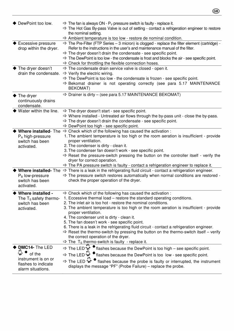
� DewPoint too low. � The fan is always ON - PV pressure switch is faulty - replace it.
� The Hot Gas By-pass Valve is out of setting - contact a refrigeration engineer to restore the nominal setting.
� Ambient temperature is too low - restore de nominal condition.
� Excessive pressure drop within the dryer.
� The Pre-Filter (FTP Series – 3 micron) is clogged - replace the filter element (cartridge) - Refer to the instructions in the user’s and maintenance manual of the filter.
� The dryer doesn’t drain the condensate - see specific point.
� The DewPoint is too low - the condensate is frost and blocks the air - see specific point.
� Check for throttling the flexible connection hoses.
� The dryer doesn’t drain the condensate.
� The condensate drain service valve is closed - open it.
� Verify the electric wiring.
� The DewPoint is too low - the condensate is frozen - see specific point.
� Bekomat drainer is not operating correctly (see para 5.17 MAINTENANCE BEKOMAT)
� The dryer continuously drains condensate.
� Drainer is dirty – (see para 5.17 MAINTENANCE BEKOMAT)
� Water within the line. � The dryer doesn't start - see specific point.
� Where installed - Untreated air flows through the by-pass unit - close the by-pass.
� The dryer doesn’t drain the condensate - see specific point.
� DewPoint too high - see specific point.
� Where installed- The PA high-pressure switch has been activated.
� Check which of the following has caused the activation : 1. The ambient temperature is too high or the room aeration is insufficient - provide
proper ventilation. 2. The condenser is dirty - clean it. 3. The condenser fan doesn’t work - see specific point.
� Reset the pressure-switch pressing the button on the controller itself - verify the dryer for correct operation.
� The PA pressure switch is faulty - contact a refrigeration engineer to replace it.
� Where installed- The PB low-pressure switch has been activated.
� There is a leak in the refrigerating fluid circuit - contact a refrigeration engineer.
� The pressure switch restores automatically when normal conditions are restored - check the proper operation of the dryer.
� Where installed - The TS safety thermo-switch has been activated.
� Check which of the following has caused the activation : 1. Eccessive thermal load – restore the standard operating conditions. 2. The inlet air is too hot - restore the nominal conditions. 3. The ambient temperature is too high or the room aeration is insufficient - provide
proper ventilation. 4. The condenser unit is dirty - clean it. 5. The fan doesn’t work - see specific point. 6. There is a leak in the refrigerating fluid circuit - contact a refrigeration engineer.
� Reset the thermo-switch by pressing the button on the thermo-switch itself – verify the correct operation of the dryer.
� The TS thermo-switch is faulty - replace it.
� DMC14- The LED
of the instrument is on or flashes to indicate alarm situations.
� The LED flashes because the DewPoint is too high – see specific point.
� The LED flashes because the DewPoint is too low - see specific point.
� The LED flashes because the probe is faulty or interrupted, the instrument displays the message “PF” (Probe Failure) – replace the probe.
GB
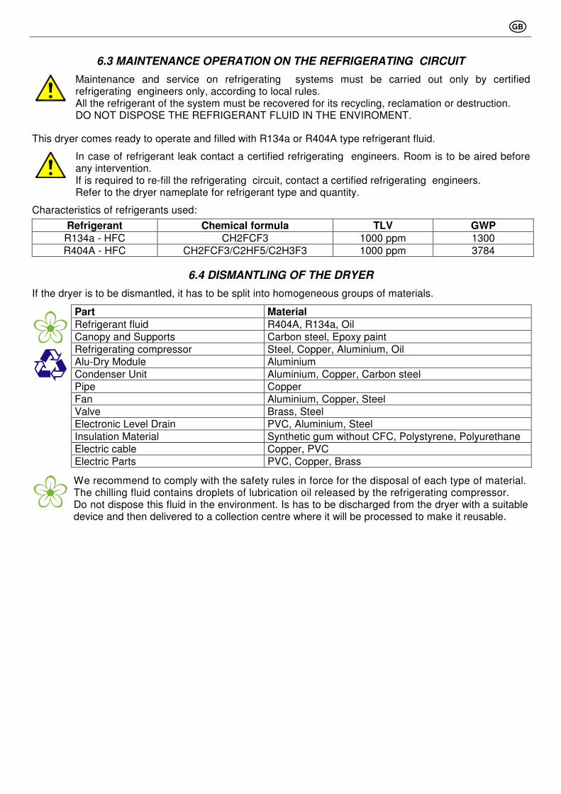
6.3 MAINTENANCE OPERATION ON THE REFRIGERATING CIRCUIT
Maintenance and service on refrigerating systems must be carried out only by certified refrigerating engineers only, according to local rules. All the refrigerant of the system must be recovered for its recycling, reclamation or destruction. DO NOT DISPOSE THE REFRIGERANT FLUID IN THE ENVIROMENT.
This dryer comes ready to operate and filled with R134a or R404A type refrigerant fluid.
In case of refrigerant leak contact a certified refrigerating engineers. Room is to be aired before any intervention. If is required to re-fill the refrigerating circuit, contact a certified refrigerating engineers. Refer to the dryer nameplate for refrigerant type and quantity.
Characteristics of refrigerants used:
Refrigerant Chemical formula TLV GWP R134a - HFC CH2FCF3 1000 ppm 1300
R404A - HFC CH2FCF3/C2HF5/C2H3F3 1000 ppm 3784
6.4 DISMANTLING OF THE DRYER
If the dryer is to be dismantled, it has to be split into homogeneous groups of materials.
Part Material Refrigerant fluid R404A, R134a, Oil
Canopy and Supports Carbon steel, Epoxy paint
Refrigerating compressor Steel, Copper, Aluminium, Oil
Alu-Dry Module Aluminium
Condenser Unit Aluminium, Copper, Carbon steel
Pipe Copper
Fan Aluminium, Copper, Steel
Valve Brass, Steel
Electronic Level Drain PVC, Aluminium, Steel
Insulation Material Synthetic gum without CFC, Polystyrene, Polyurethane
Electric cable Copper, PVC
Electric Parts PVC, Copper, Brass
We recommend to comply with the safety rules in force for the disposal of each type of material. The chilling fluid contains droplets of lubrication oil released by the refrigerating compressor. Do not dispose this fluid in the environment. Is has to be discharged from the dryer with a suitable device and then delivered to a collection centre where it will be processed to make it reusable.
GB
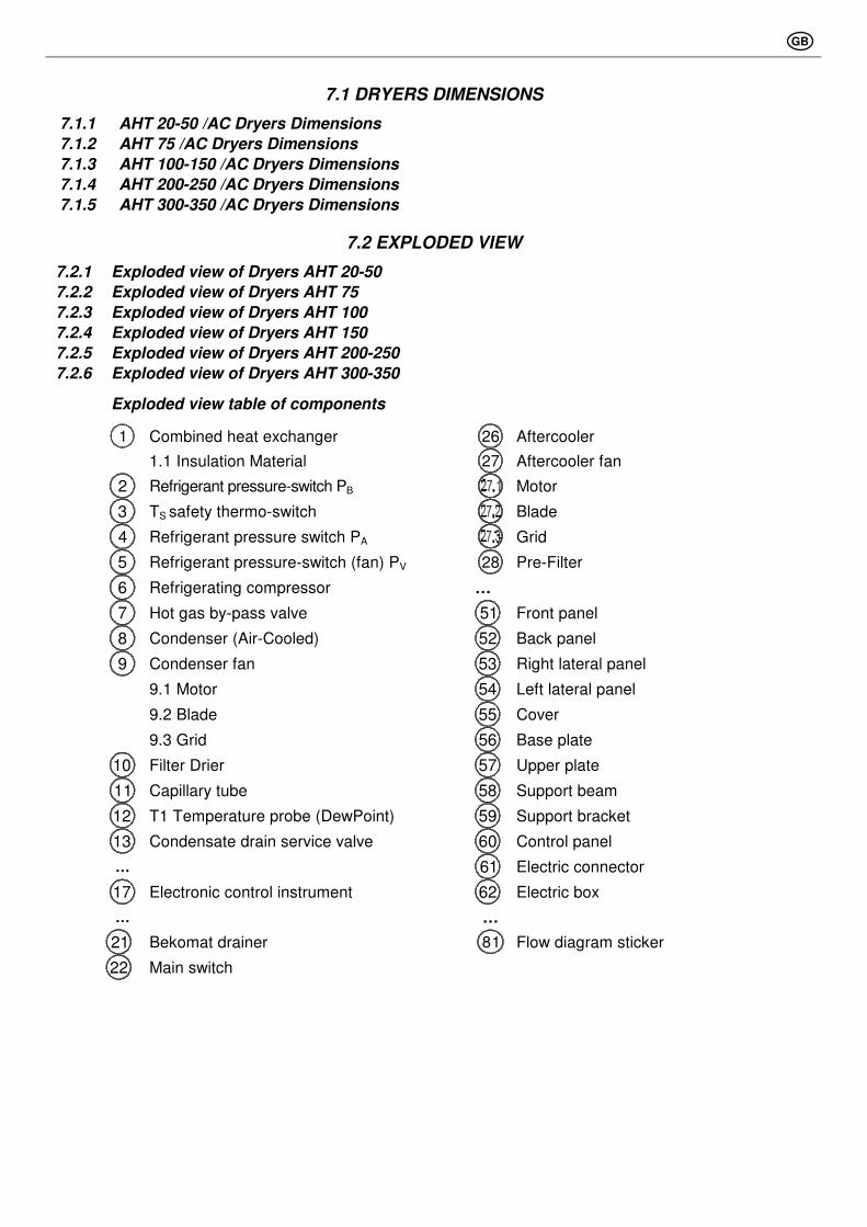
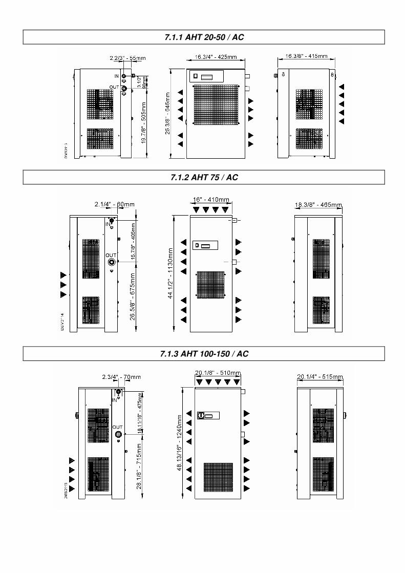
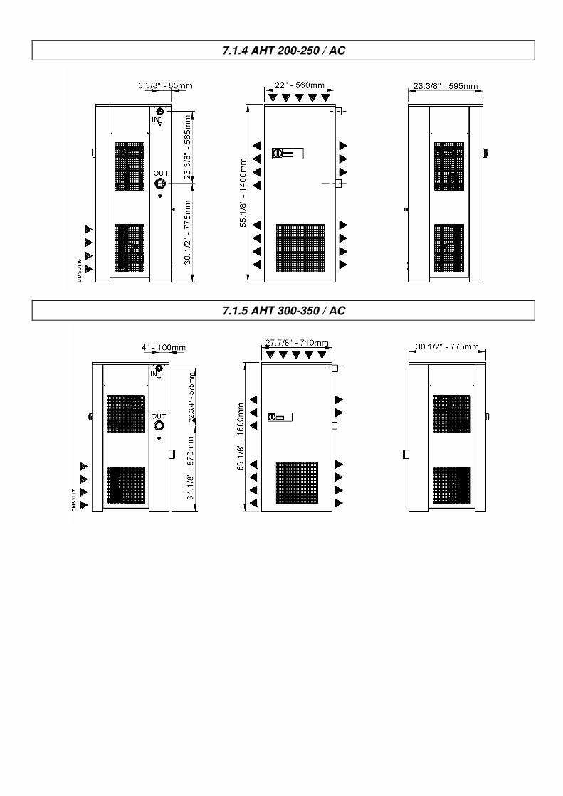
7.1 DRYERS DIMENSIONS
7.1.1 AHT 20-50 /AC Dryers Dimensions
7.1.2 AHT 75 /AC Dryers Dimensions
7.1.3 AHT 100-150 /AC Dryers Dimensions
7.1.4 AHT 200-250 /AC Dryers Dimensions
7.1.5 AHT 300-350 /AC Dryers Dimensions
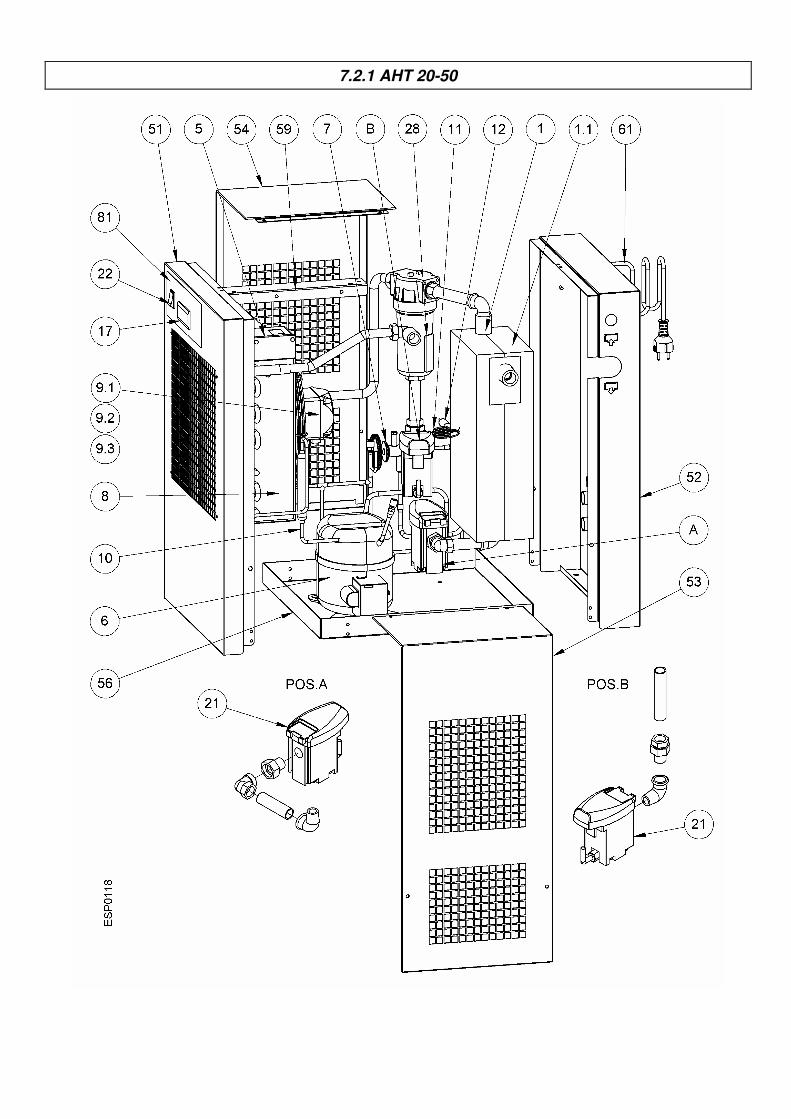
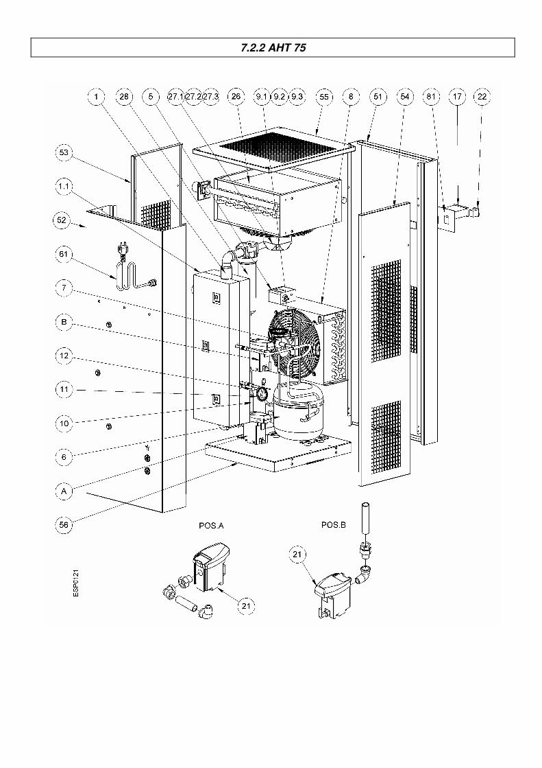
7.2 EXPLODED VIEW
7.2.1 Exploded view of Dryers AHT 20-50
7.2.2 Exploded view of Dryers AHT 75
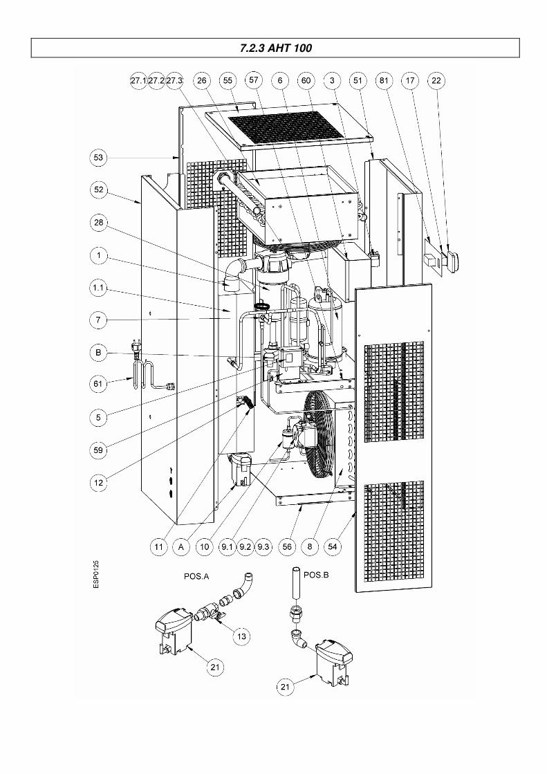
7.2.3 Exploded view of Dryers AHT 100
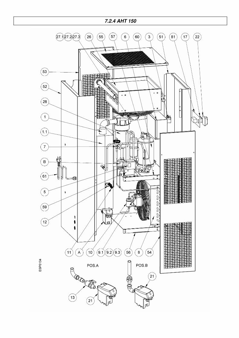
7.2.4 Exploded view of Dryers AHT 150
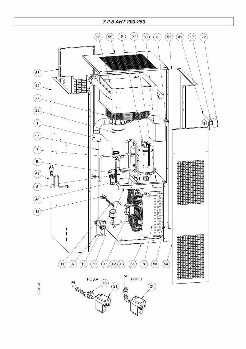
7.2.5 Exploded view of Dryers AHT 200-250
7.2.6 Exploded view of Dryers AHT 300-350
Exploded view table of components
1 Combined heat exchanger 26 Aftercooler
1.1 Insulation Material 27 Aftercooler fan
2 Refrigerant pressure-switch PB Motor
3 TS safety thermo-switch Blade
4 Refrigerant pressure switch PA Grid
5 Refrigerant pressure-switch (fan) PV 28 Pre-Filter
6 Refrigerating compressor …
7 Hot gas by-pass valve 51 Front panel
8 Condenser (Air-Cooled) 52 Back panel
9 Condenser fan 53 Right lateral panel
9.1 Motor 54 Left lateral panel
9.2 Blade 55 Cover
9.3 Grid 56 Base plate
10 Filter Drier 57 Upper plate
11 Capillary tube 58 Support beam
12 T1 Temperature probe (DewPoint) 59 Support bracket
13 Condensate drain service valve 60 Control panel
… 61 Electric connector
17 Electronic control instrument 62 Electric box
… …
21 Bekomat drainer 81 Flow diagram sticker
22 Main switch
GB
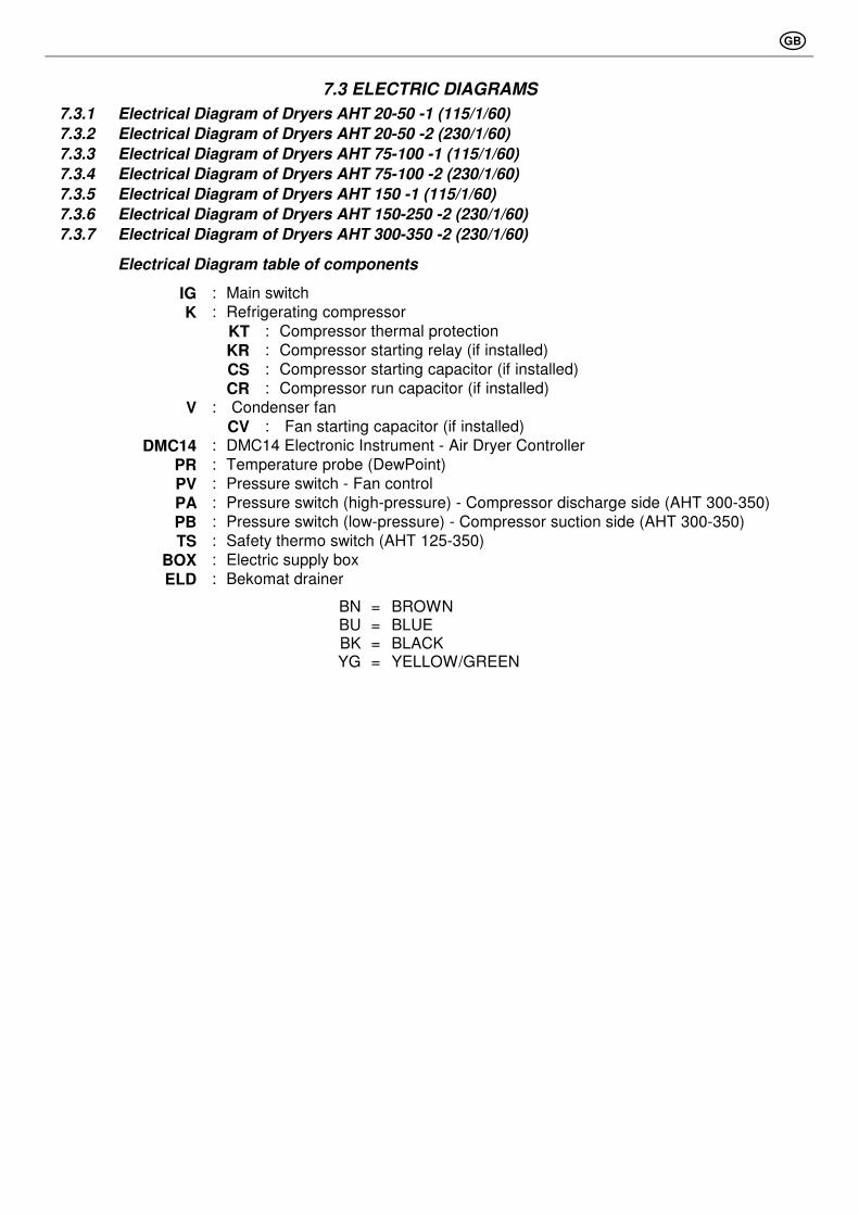
7.3 ELECTRIC DIAGRAMS
7.3.1 Electrical Diagram of Dryers AHT 20-50 -1 (115/1/60)
7.3.2 Electrical Diagram of Dryers AHT 20-50 -2 (230/1/60)
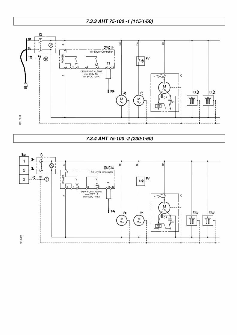
7.3.3 Electrical Diagram of Dryers AHT 75-100 -1 (115/1/60)
7.3.4 Electrical Diagram of Dryers AHT 75-100 -2 (230/1/60)
7.3.5 Electrical Diagram of Dryers AHT 150 -1 (115/1/60)
7.3.6 Electrical Diagram of Dryers AHT 150-250 -2 (230/1/60)
7.3.7 Electrical Diagram of Dryers AHT 300-350 -2 (230/1/60)
Electrical Diagram table of components
IG : Main switch
K : Refrigerating compressor
KT : Compressor thermal protection
KR : Compressor starting relay (if installed)
CS : Compressor starting capacitor (if installed)
CR : Compressor run capacitor (if installed)
V : Condenser fan
CV : Fan starting capacitor (if installed)
DMC14 : DMC14 Electronic Instrument - Air Dryer Controller
PR : Temperature probe (DewPoint)
PV : Pressure switch - Fan control
PA : Pressure switch (high-pressure) - Compressor discharge side (AHT 300-350)
PB : Pressure switch (low-pressure) - Compressor suction side (AHT 300-350)
TS : Safety thermo switch (AHT 125-350)
BOX : Electric supply box
ELD : Bekomat drainer
BN = BROWN BU = BLUE BK = BLACK YG = YELLOW/GREEN

7425MUM020_AT Rev00
ATTACHMENTS
ANNEXES
GB GB
F F
7.1.1 AHT 20-50 / AC
7.1.2 AHT 75 / AC
7.1.3 AHT 100-150 / AC
7.1.4 AHT 200-250 / AC
7.1.5 AHT 300-350 / AC
7.2.1 AHT 20-50
7.2.2 AHT 75
7.2.3 AHT 100
7.2.4 AHT 150
7.2.5 AHT 200-250

7.2.6 AHT 300-350

7.3.1 AHT 20-50 -1 (115/1/60)
DEW-POINT ALARM
PO
WE
R2
2 4 53
3
min 5VDC 10mA
8 9
T111 12
M
KR
CR
M
A P
C
KT
CS
Bn
Air Dryer Controller
Bn
SE
L0
05
0
max 250V 1A
7.3.2 AHT 20-50 -2 (230/1/60)
DEW-POINT ALARM
PO
WE
R2
2 4 5
3
3
min 5VDC 10mA
8 9
T111 12
M
KR
CR
M
A P
C
KT
CS
Bn
Air Dryer Controller
Bn
SE
L005
7
max 250V 1A
2
3
1
7.3.3 AHT 75-100 -1 (115/1/60)
DEW-POINT ALARM
PO
WE
R2
2 4 5
3
3
8 9
T111 12
M
KR
CR
M
A P
C
KT
CS
Bn
Air Dryer Controller
Bn
Bn
M
SE
L0051
min 5VDC 10mAmax 250V 1A
7.3.4 AHT 75-100 -2 (230/1/60)
DEW-POINT ALARM
PO
WE
R2
2 4 5
3
3
8 9
T111 12
M
KR
CR
M
A P
C
KT
CS
Bn
Air Dryer Controller
Bn
Bn
M
SE
L0
05
8
min 5VDC 10mAmax 250V 1A
2
3
1

7.3.5 AHT 150 -1 (115/1/60)
DEW-POINT ALARM
PO
WE
R2
2 4 5
3
3
CVC
8 9
T111 12
M MC
KT
CS
Bn
Air Dryer Controller
Bn
C
SR
M
Bn
CVA
SE
L00
52
min 5VDC 10mAmax 250V 1A
7.3.6 AHT 150-250 -2 (230/1/60)
DEW-POINT ALARM
PO
WE
R2
2 4 5
3
3
CVC
8 9
T111 12
M MC
KT
CS
Bn
Air Dryer Controller
Bn
C
SR
M
Bn
CVA
SE
L0059
min 5VDC 10mAmax 250V 1A
2
3
1
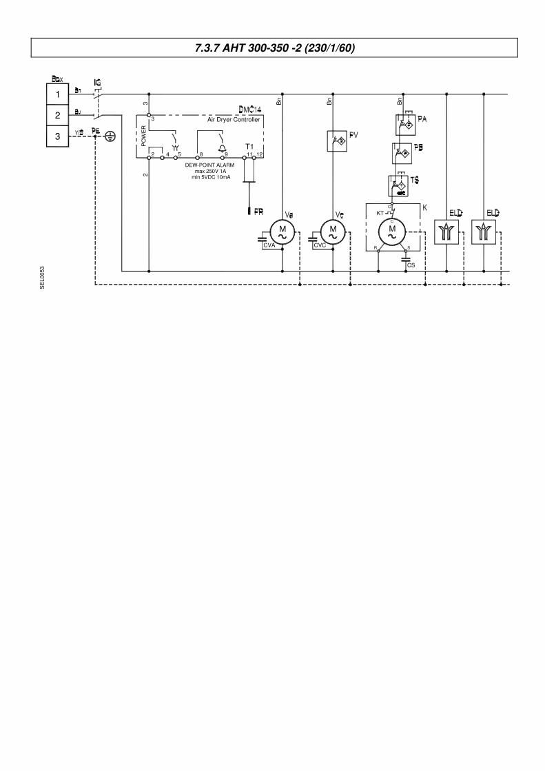
7.3.7 AHT 300-350 -2 (230/1/60)
Air Dryer Controller3
3
2 4 5 11 12
2P
OW
ER
M
CVC
Bn
Bn
3
2
1
9
DEW-POINT ALARM
T18
KT
R
CS
S
MC
C
M
Bn
CVA
SE
L005
3
min 5VDC 10mAmax 250V 1A