Embed Size (px)
Citation preview

AHM-6xx0 User Manual 1
AHM-6xx0
User Manual
Release Date Revision
Oct 2010 V1.0
Feb 2012 V1.1
®2010 Aplex Technology, Inc. All Rights Reserved. Published in Taiwan
Aplex Technology, Inc.
15F-1, No.186, Jian Yi Road, Zhonghe District, New Taipei City 235, Taiwan
Tel: 886-2-82262881 Fax: 886-2-82262883 E-mail: [email protected] URL:
www.aplex.com.tw

AHM-6xx0 User Manual 2
Warning!___________________________________
This equipment generates, uses and can radiate radio frequency energy and if not installed and
used in accordance with the instructions manual, it may cause interference to radio communications.
It has been tested and found to comply with the limits for a Class A computing device pursuant to
FCC Rules, which are designed to provide reasonable protection against such interference when
operated in a commercial environment. Operation of this equipment in a residential area is likely
to cause interference in which case the user at his own expense will be required to take whatever
measures may be required to correct the interference.
Disclaimer
This information in this document is subject to change without notice. In no event shall Aplex Technology
Inc. be liable for damages of any kind, whether incidental or consequential, arising from either the use or
misuse of information in this document or in any related materials.
Electric Shock Hazard – Do not operate the machine with its back cover removed. There are
dangerous high voltages inside.

AHM-6xx0 User Manual 3
Packing List
Accessories (as ticked) included in this package are: □ AC power cable □ 12V/60W Power adapter □ Driver & manual CD disc □ Other.___________________(please specify)
Safety Precautions Follow the messages below to prevent your systems from damage:
◆ Avoid your system from static electricity on all occasions.
◆ Prevent electric shock. Don‘t touch any components of this card when the card is
power-on. Always disconnect power when the system is not in use.
◆ Disconnect power when you change any hardware devices. For instance, when you
connect a jumper or install any cards, a surge of power may damage the electronic
components or the whole system.

AHM-6xx0 User Manual 4
Table of Contents______________________
Warning!…………………………………………………………………………….……..….2 Disclaimer………………………………………………………………….…………………2 Packing List…………………………………………………………………………………..3 Safety Precautions…………………………………………………………………………..3
Chapter 1 Getting Started
1.1 & 1.2 Specifications..…….……………………………………..…..…...…5 1.3 Brief Description of AHM-6xx0…………….…..…………………………..6 1.4 Mainboard…………...…………………………………………………..…..7 1.5 Chassis Dimensions…………………………………………………..……8 1.6 Mounting Type……………………………………………………………..13
Chapter 2 I/O Definitions
2.1 I/O Definitions…………………..………………….………………...........15
Figures
Figure 1.1: Front View of AHM-6xx0…………………………………..……….6 Figure 1.2: Rear View of AHM-6100…………….……….…………………….6 Figure 1.3: Bird Eye’s View of Mainboard…..…………..……………………..7 Figure 1.4:Dimensions of the AHM-6050..……………………...……………..8 Figure 1.5: Dimensions of the AHM-6080……………………………………...9 Figure 1.6: Dimensions of the AHM-6100…………………………………….10 Figure 1.7: Dimensions of the AHM-6120…………………………………….11 Figure 1.8: Dimensions of the AHM-6150…………………………………….12 Figure 1.9: Panel mounting of AHM-6xx0…………………………………….13 Figure 1.10: VESA mounting of AHM-6xx0….......……………………...…..14
Appendix
SBC-7102 new Boot loader/ OS image update by SD card.……………….25

AHM-6xx0 User Manual 5
Chapter 1 System 1. Brief Hardware Specifications
1.1 System Architectures
Model AHM-6050 AHM-6080 AHM-6010 AHM-6121 AHM-6151
Display 5.7” 8” TFT LCD 10.4” TFT LCD 12.1” TFT LCD 15” TFT LCD
Resolution
Luminance
(cd/m²)
640x480
400
800x600
400
640x480
250
800x600
350
1024x768
300
CPU Samsung S3C2440A-40 400Mhz
Memory 128MB SDRAM , 16MB Video Memory
Storage 128MB NAND Flash, 2MB NOR Flash, 32KB FRAM
1 x SD slot (support SD/SDHC card, up to 32GB, support Plug & Play)
Graphic Silicon Image SM502 (only for AHM-6050, AHM-6080, AHM-6120, AHM-6150)
Touch Panel Resister type
I/O port 2 x USB 1.1 Host connector
1 x RJ-45 LAN connector
1 x DB-9 RS232 (COM 1)
1 x DB-9 RS422/485, Default RS-485
1 x Line-out (for AHM-6100/6120/6150)
1 x 3-pin DC Power input terminal
Wireless LAN Q-COM LR802UKN3 USB module is integrated (Option)
Power Input DC 9-32V
Construction Plastic molding front panel and metal housing/Black
IP Rating NEMA 4/ IP 65 compliant front panel
Dimensions
(WxHxD/mm) 204x149x61mm 231x176x57mm 270x212x57mm 247x243x57mm 409x309x59mm
OS Support Windows® CE 5.0
1.2 Environment Operating temp.
humidity 0~50℃, 10~90% @40˚C non-condensing
Storage temp.
humidity -20~60℃, 10~90% @40˚C non-condensing
Vibration 1G/5-500Hz (Random) / Operation
Shock 15G peak acceleration (11msec. duration) / Operation
Certificate Meet CE/FCC Class A
Waterproof Front Panel IP65
Specs

AHM-6xx0 User Manual 6
1.3 Brief Description of the AHM-6xx0
The AHM-6xx0 is built around the Samsung S3C2440A-40 CPU with a clock rate of 400MHz. The
models come with an 8-inch TFT LCD display with luminance of 400 cd/m²/a 10.4-inch TFT LCD
display with 400 cd/m²/a 12.1-inch display with 250 cd/m², 15-inch display with 300 cd/m²a NEMA
4/IP65 compliant front panel, a SD slot, a DC 9-32V power input, and so forth. This industrial HMI
series also features two COM ports, two USB ports and one LAN port. It is ideal for use as a PC-based
controller for Automotive, Logistic Process, Materials Handling, and Kiosk applications.
Figure 1.1: Front View of AHM-6xx0
Figure 1.2: Rear View of AHM-6100

AHM-6xx0 User Manual 7
1.4 Mainboard
Figure 1.3: Bird’s Eyeview of Mainboard
AHM-6xx0 User Manual 8
1.5 Chassis Dimensions
Figure 1.4: Dimensions of the AHM-6050

AHM-6xx0 User Manual 9
Figure 1.5: Dimensions of the AHM-6080

AHM-6xx0 User Manual 10
Figure 1.6: Dimensions of the AHM-6100

AHM-6xx0 User Manual 11
Figure 1.7: Dimensions of the AHM-6120

AHM-6xx0 User Manual 12
Figure 1.8: Dimensions of the AHM-6150
AHM-6xx0 User Manual 13
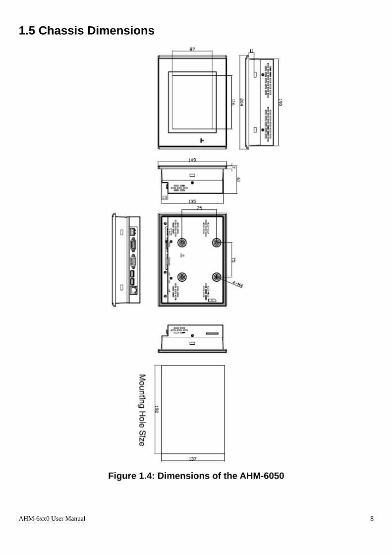
1.6 Mounting Type
A. Panel Mounting:
The AHM-6xx0 HMI Controller is designed to be panel-mounted as shown in Figure. Just carefully
place the unit through the hole and tighten the given 9 screws from the rear to secure the mounting.
Figure 1.9: Panel mounting of AHM-6xx0

AHM-6xx0 User Manual 14
B. VESA Mounting
The AHM-6xx0 display monitor is mounted by means of VESA. Just carefully mount the arm onto the
rear of the unit by fastening the given four screws as shown in Figure
Figure 1.10: VESA mounting of AHM-6xx0

AHM-6xx0 User Manual 15
Chapter 2 I/O Definitions SBC- 7102 Block Diagram: SBC-7102 is designed 4”, EPIC SBC with build-in SAMSUNG RISC-based S3C2440A(ARM920T
core)as SoC computing engine with add- on SM502 graphic- controller may enable up to 1024x 768
resolution of 18-/ 24-bit LVDS panel target to green-/ embedded application market
SBC- 7102 Board Overview of SBC- 7102 PCB

AHM-6xx0 User Manual 16

AHM-6xx0 User Manual 17

AHM-6xx0 User Manual 18

AHM-6xx0 User Manual 19

AHM-6xx0 User Manual 20

AHM-6xx0 User Manual 21

AHM-6xx0 User Manual 22
AHM-6xx0 User Manual 23

AHM-6xx0 User Manual 24

AHM-6xx0 User Manual 25
Appendix
SBC-7102 new Bootloader/ OS image update by SD card
3.1, Update Process:
4.1. New update OS or customized LOGO form SD card process on Aplex AHM-6xx0 family.
3.2, SD Card update steps:
1st. step to check and store all of your new Update Bootloader files onto your SD card,
2nd. step to put Your SD Card inside our SBC-7102 SD card slot.
3rd. step, Before system Power ON, you may connect Pin 7 & 8 together on COM1, DB9 socket
as closed-loop, or you may remake a DB9 plug with wired both Pin 7 & 8 as your personal key as
tooling.

AHM-6xx0 User Manual 26
3.3, SD Card update flow:
3.4, SD Card update process description:
3.4.1. Check loop-back:
Our new Aplex Bootloader for AHM-6xx0 family, will auto-detect the SBC-7102 COM 1 pin 7 &
pin 8, If they are open- loop status, system will generate beep once, and go to normal power- on
process. If they are closed-loop status, system is going to “ SD Update” mode, then auto detect
inside the SD card where new bootloader as well as new OS image will be update automatically.
3.4.2. Check SD Card:
Aplex designed SD slot onto SBC-7102 forAHM-6xx0 family may support SD2.0 like SDHC ( up
to 32GB) standard,only support FAT16 / FAT32,but NOT support NTFS format, please note!
3.4.3. Check if new Image?
System will auto-detect SD card inside if any file named ” Logo.BMP ” or “NK.bin” ? please note,
these files need to put direct on the root directory of SD files!
“Logo.BMP” if this file adapt display size and resolution and as same format of 24bpp,it will
be updated file and reboot with new LOGO like your Logo.BMP.
“NK.bin” as WinCE 5.0 OS image,if it matched format, system will auto update it from next

AHM-6xx0 User Manual 27
bootup.
3.4.4. Update failed:
If there are some errors happened as follow list, system will generate a continuous long beep
sound as warning to the user to remove your action before, and power-on like before again.
3.4.4.1, Like no SD card found…
3.4.4.2, If detected SD card fails…
3.4.4.3, Found no OS image inside SD Card…
3.4.4.4, OS image updated but failure from any undefined reason, boot fails etc…
3.4.5. Boot New OS:
If above update process and flow correct and OK, system will be power-on with new OS boot。
After new OS boot success, please remove the closed-loop on Pin 7 & 8 of COM1, DB9 port ,to
avoid any update as mistake of next boot-up like update new OS image again…