Embed Size (px)
Citation preview

Rank Brothers Ltd
Issue 1a June 2017
Manufactured by: Rank Brothers Ltd
56 High Street, Bottisham, Cambridge CB25 9DA, England Tel: +44 (0)1223 811369 Fax: +44 (0)1223 811441
Website: http://www.rankbrothers.co.uk/
Agrochemical Emulsion Tester AET100
Operating Manual
Agrochemical Emulsion Tester AET100
2
Contents 1. Getting Started ................................................................................................................. 5
1.1 Do Not ........................................................................................................................ 5
1.2 Do ............................................................................................................................... 5
1.3 Connection to your Mains Supply .............................................................................. 5
2. Controls ............................................................................................................................ 6
2.1 On/Off Switch ............................................................................................................. 6
2.2 Laser Supply Switch .................................................................................................... 6
2.3 dc Switch .................................................................................................................... 6
2.4 Display ........................................................................................................................ 7
2.5 Recorder Output ........................................................................................................ 7
2.6 Overload Indicators .................................................................................................... 7
2.6.1 Turbidity .............................................................................................................. 7
2.6.2 Signal ................................................................................................................... 7
2.7 The Cell ....................................................................................................................... 7
2.8 The Validation Unit .................................................................................................... 8
3. Operation ......................................................................................................................... 8
3.1 Insertion of the Glass Capillary Tube ......................................................................... 8
3.2 Sample Flow Rates ..................................................................................................... 8
4. Theory of Operation ......................................................................................................... 9
5. Specifications ................................................................................................................. 10
5.1 Laser ......................................................................................................................... 10
5.2 General ..................................................................................................................... 10
5.3 Instrument Labels .................................................................................................... 11
MT 183 THE USE OF THE AGROCHEMICAL EMULSION TESTER (AET) FOR THE DETERMINATION OF THE STABILITY OF DILUTE EMULSIONS ............................................ 12
SCOPE ............................................................................................................................. 12
OUTLINE OF METHOD .................................................................................................... 12
REAGENTS ...................................................................................................................... 12
APPARATUS .................................................................................................................... 12
Rank Brothers Ltd
3
PROCEDURE ................................................................................................................... 13
(a) Instrument validation ........................................................................................... 13
(b) Setting up the AET for analysis ............................................................................. 13
(c) Preparation of dilute emulsions for measurement............................................... 14
(d) Obtaining an AET reading for a dilute emulsion ................................................... 15
Agrochemical Emulsion Tester AET100
4
Warranty We guarantee the manufacture of the instrument and parts against faults for a period of twelve months from the invoice date.
If a fault should occur within this period then we undertake to either:
Supply free of charge replacement parts for you to fit to the instrument.
Upon return of the item at your expense, repair or replace (at our discretion) the instrument free of charge and return it to you at our expense.
Rank Brothers Ltd
5
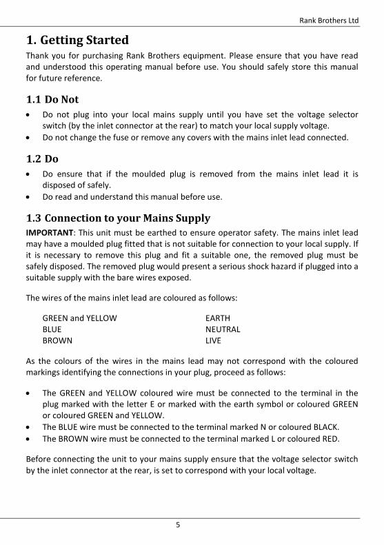
1. Getting Started Thank you for purchasing Rank Brothers equipment. Please ensure that you have read and understood this operating manual before use. You should safely store this manual for future reference.
1.1 Do Not
Do not plug into your local mains supply until you have set the voltage selector switch (by the inlet connector at the rear) to match your local supply voltage.
Do not change the fuse or remove any covers with the mains inlet lead connected.
1.2 Do
Do ensure that if the moulded plug is removed from the mains inlet lead it is disposed of safely.
Do read and understand this manual before use.
1.3 Connection to your Mains Supply
IMPORTANT: This unit must be earthed to ensure operator safety. The mains inlet lead may have a moulded plug fitted that is not suitable for connection to your local supply. If it is necessary to remove this plug and fit a suitable one, the removed plug must be safely disposed. The removed plug would present a serious shock hazard if plugged into a suitable supply with the bare wires exposed.
The wires of the mains inlet lead are coloured as follows:
GREEN and YELLOW EARTH BLUE NEUTRAL BROWN LIVE
As the colours of the wires in the mains lead may not correspond with the coloured markings identifying the connections in your plug, proceed as follows:
The GREEN and YELLOW coloured wire must be connected to the terminal in the plug marked with the letter E or marked with the earth symbol or coloured GREEN or coloured GREEN and YELLOW.
The BLUE wire must be connected to the terminal marked N or coloured BLACK.
The BROWN wire must be connected to the terminal marked L or coloured RED.
Before connecting the unit to your mains supply ensure that the voltage selector switch by the inlet connector at the rear, is set to correspond with your local voltage.
Agrochemical Emulsion Tester AET100
6
For operator safety only the correct fuse must be used, failure to comply will result in reduced protection of the operator to fault conditions. Before changing a fuse disconnect the mains inlet lead from the instrument. The correct fuse is as follows:
220/240 V T160mA 110/120 V T200mA
WARNING: This unit contains a Class II (CDRH) Class 2 (IEC) Laser. Do not stare into the beam. (This hazard only exists with the cover removed and the fibre optic removed from the laser module.)
CAUTION: Use of controls, adjustments or performance of procedures other than those specified in this manual may result in hazardous radiation exposure.
The unit contains no user serviceable parts. The cover should be removed by competent personnel only, after first switching off the power supply and disconnecting the mains inlet lead.
For any servicing or repairs, the unit should be returned to the manufacturer with a covering letter. Please ensure the unit is carefully packaged to avoid damage during shipment.
2. Controls The instrument is designed to be as simple to use as possible and thus has the minimum controls necessary.
2.1 On/Off Switch
The on/off switch is located at the rear of the instrument, above the power inlet connector. The display is illuminated when the instrument is switched on.
2.2 Laser Supply Switch
This switch is located on the front of the instrument. It is a push button switch and is illuminated red when the laser is switched on. The laser should be switched off while changing the cell capillary or inserting the validation unit to minimise any possible laser radiation hazard. Note the Turbidity Overload indictor will be illuminated while the laser is switched off.
2.3 dc Switch
This switch is located on the front panel and displays the dc voltage from the first amplifier stage of the instrument. The dc voltage is set to a nominal 10 V when clean water is flowing through the cell. This value will be reduced with a sample in the cell, the reduction giving an indication of the turbidity. Should the dc value drop below 80 mV,
Rank Brothers Ltd
7
the Turbidity Overload indicator will be illuminated, showing that there is insufficient light being received to obtain a reading. If the dc value, with clean water flowing, drops below 5 V then the cell should be cleaned or replaced.
2.4 Display
The display shows the ac component of the signal from the receiving electronics. The value gives an indication of the stability of an emulsion. The value increases dramatically with increases in droplet size, and less significantly by increasing the concentration, thus poor emulsions will give high readings. Typically, readings below 0.50 with 1% dilutions indicate a stable emulsion, although this reading varies from one formulation to another, and will need to be confirmed by correlation with the manual test.
2.5 Recorder Output
This BNC socket is connected in parallel to the display and has a 0 to 13 V output that may be connected to a chart recorder or data logger.
2.6 Overload Indicators
These two indicators illuminate to warn the user that the reading displayed is not accurate. Note no damage will occur to the instrument if operated with either or both indicators illuminated.
2.6.1 Turbidity
This indicator as mentioned above will illuminate when the dc voltage drops below 80 mV. This will occur if the turbidity of the sample is too high and/or the sample tube is very contaminated. The electronics maintains the dc at 80 mV and thus if the signal drops below this value the readings displayed will not be accurate.
2.6.2 Signal
This indicator illuminates when the ac component of the signal is very large causing the 'rms to dc' circuit to overload giving inaccurate readings. The commonest cause of this indicator illuminating is when air bubbles pass through the cell. In normal circumstances, if the sample causes the indicator to illuminate then the reading would be very high (over 5.00) and the emulsion would likely be extremely unstable.
2.7 The Cell
The cell has a simple clamp to hold the glass capillary section. The knurled screw should be rotated in the direction of the arrows to either open or close the movable jaw. The glass capillary should be clamped reasonably tight by inserting it into the vertical slot in the movable jaw and then closing the jaw. The capillary should be held so that the flexible connecting tube touches the bottom of the clamping jaw, reducing the possibility of kinking. The capillary supplied is precision bore tube, and should be replaced only by
Agrochemical Emulsion Tester AET100
8
an equivalent size, available from us. Using capillary of the wrong bore diameter will alter the calibration of the instrument.
2.8 The Validation Unit
The validation unit is held in its storage clamp on the right-hand side of the instrument. It should be removed from the clamp and inserted in the cell. The cell clamping jaw will need to be fully open, so that the unit can locate into both the fixed and clamping jaw. Close the clamping jaw tightly and plug the unit into the validation unit socket to the left of the cell. The instrument will now settle to a stable reading, which should be noted. Deviations of more than 5% from the validation unit's stated reading would indicate that the instrument will need recalibrating. Note the validation unit only detects problems with either the gain of the electronics or problems with the optical system. Obviously, it is not able to detect incorrect capillary size.
After taking a reading, return the validation unit to its storage clamp, using the hole on the underside to retain the plug. The glass capillary can now be reclamped into the cell.
3. Operation The instrument should prove to be simple and easy to operate. The following instructions detail the main operations.
3.1 Insertion of the Glass Capillary Tube
To open the movable cell jaw and remove the old cell, rotate the knurled ring on the cell in the direction of the open arrow. The new capillary can now be inserted in the vertical slot of the movable jaw and the knurled ring rotated in the opposite direction until the capillary is clamped tight in the cell. The ring can be clamped reasonable tight without damage to the capillary and should hold it tight enough to prevent slipping in the slot. Note slight sideways movement may occur, as the slot is intentionally slightly wider than the diameter of the capillary.
The instrument is supplied with 2 mm bore silicone tubing to connect to the capillary. This tubing carries the sample from the sample vessel, through the instrument, to waste. It is preferable to have the capillary as high as possible in the cell to avoid kinking the silicone tube.
3.2 Sample Flow Rates
The instrument has been designed to work with a sample flow rate of 10 ml per minute. The rate should be controlled to within 10% of this value. The simplest way to achieve this is to allow the sample to siphon from one beaker to another with a head of 20 to 30 cm. Then the flow rate can be controlled by using a screw clamp on the tube, restricting the flow to the correct rate. The clamp should be on the silicone tube
Rank Brothers Ltd
9
between the instrument and the waste beaker to ensure the sample is not altered by passing through the restriction.
It may be found that varying the flow rate outside the 9–11 ml range does not give any difference in the rms reading. The electronics however, have been optimised to give the most accurate results with rates of at least 5 ml per minute. At higher flow rates than 11 ml per minute, formulations may be damaged by the high shearing in the capillary tube. The above flow rate should thus he used to ensure the maximum accuracy of the readings.
4. Theory of Operation The instrument uses a laser diode module to illuminate emulsion droplets (or particles) flowing in the glass capillary cell. The light passing through the sample is then converted to an electrical signal by a photodiode detector. The resultant voltage signal consists of a fluctuating signal offset from zero volts. The smoothed signal gives an average value (the dc value) and the fluctuating component (the rms or ac value).
The signal from the detector is amplified so that the dc value is typically 10 volts with clean water in the cell, and the rms value should be under 0.1 volts (depending on the quality of the water). The signal is then attenuated to a fixed voltage (about 80 millivolts) so that the dc remains constant, regardless of sample turbidity. The signal is then ac coupled to remove the dc component, amplified and converted to an equivalent dc value (rms value). The resultant signal is then fed to the display.
The dc signal is kept constant to ensure that the rms signal is independent of cell wall contamination and laser intensity. If this circuit was not used, and the laser intensity dropped by, say 50%, then both the dc and rms would also drop by 50%, thus the rms signal alone would not be sufficient, however because the attenuator circuit holds the dc constant, the rms value will remain constant.
The dc value gives an indication of the turbidity of the sample but will not provide much useful information. The rms value is very sensitive to particle size, and less sensitive to particle concentration. Thus if the concentration of the sample remains the same, then the rms value increases dramatically with increased particle size, the dc will also increase slightly. The instrument is most sensitive to droplets between 0.5 microns and 100 microns although this is dependent on their refractive index relative to water.
Stable emulsions are ones that completely emulsify, resulting in a uniform droplet size as small as possible for the particular formulation. The AET will thus give low readings (typically below 0.5) for stable emulsions, increasing dramatically as the emulsion stability decreases (this is due to the formation of oil droplets and cream). Results show that the droplets form very quickly. Readings can be taken as soon as the formulation is diluted; these give good correlation to the manual 1 hour and 24 hour visual tests.
Agrochemical Emulsion Tester AET100
10
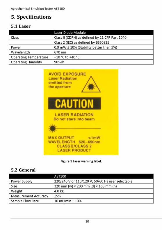
5. Specifications
5.1 Laser
Laser Diode Module
Class Class II (CDRH) as defined by 21 CFR Part 1040
Class 2 (IEC) as defined by BS60825
Power 0.9 mW ± 10% (Stability better than 5%)
Wavelength 670 nm
Operating Temperature −10 °C to +40 °C
Operating Humidity 90%rh
Figure 1 Laser warning label.
5.2 General
AET100
Power Supply 220/240 V or 110/120 V; 50/60 Hz user selectable
Size 320 mm (w) × 200 mm (d) × 165 mm (h)
Weight 4.0 kg
Measurement Accuracy ±5%
Sample Flow Rate 10 mL/min ± 10%
Rank Brothers Ltd
11
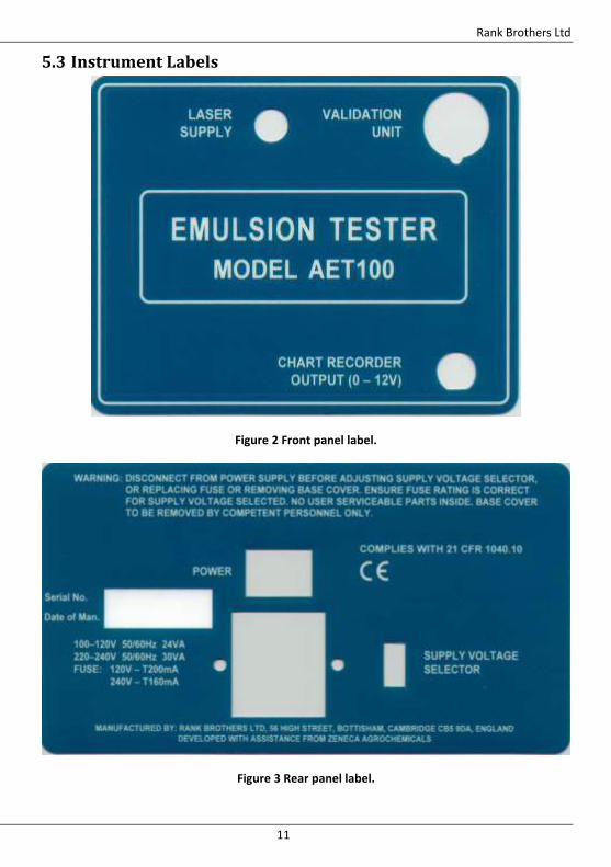
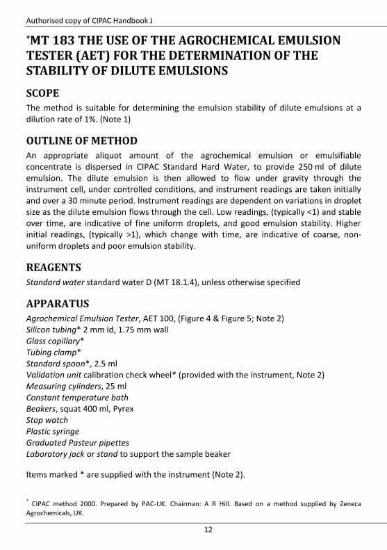
5.3 Instrument Labels
Figure 2 Front panel label.
Figure 3 Rear panel label.
Authorised copy of CIPAC Handbook J
12
*MT 183 THE USE OF THE AGROCHEMICAL EMULSION TESTER (AET) FOR THE DETERMINATION OF THE STABILITY OF DILUTE EMULSIONS
SCOPE
The method is suitable for determining the emulsion stability of dilute emulsions at a dilution rate of 1%. (Note 1)
OUTLINE OF METHOD
An appropriate aliquot amount of the agrochemical emulsion or emulsifiable concentrate is dispersed in CIPAC Standard Hard Water, to provide 250 ml of dilute emulsion. The dilute emulsion is then allowed to flow under gravity through the instrument cell, under controlled conditions, and instrument readings are taken initially and over a 30 minute period. Instrument readings are dependent on variations in droplet size as the dilute emulsion flows through the cell. Low readings, (typically <1) and stable over time, are indicative of fine uniform droplets, and good emulsion stability. Higher initial readings, (typically >1), which change with time, are indicative of coarse, non-uniform droplets and poor emulsion stability.
REAGENTS
Standard water standard water D (MT 18.1.4), unless otherwise specified
APPARATUS
Agrochemical Emulsion Tester, AET 100, (Figure 4 & Figure 5; Note 2) Silicon tubing* 2 mm id, 1.75 mm wall Glass capillary* Tubing clamp* Standard spoon*, 2.5 ml Validation unit calibration check wheel* (provided with the instrument, Note 2) Measuring cylinders, 25 ml Constant temperature bath Beakers, squat 400 ml, Pyrex Stop watch Plastic syringe Graduated Pasteur pipettes Laboratory jack or stand to support the sample beaker
Items marked * are supplied with the instrument (Note 2).
* CIPAC method 2000. Prepared by PAC-UK. Chairman: A R Hill. Based on a method supplied by Zeneca Agrochemicals, UK.
Authorised copy of CIPAC Handbook J
13
PROCEDURE
(a) Instrument validation
Prior to use the AET must be switched on. The on/off switch is located at the rear of the machine above the power socket. A 30 minute warm-up period is required before use. The AET may be left on overnight, but each time the instrument is switched off, a 30 minute warm up period is required. The AET will require a single validation check each day, using the supplied validation unit, before it is ready to measure emulsion stability. Figure 4 illustrates the AET and its components. (i) Fitting of the validation unit. After the warm up period switch off the instrument and insert the validation unit immediately. The cell clamping jaw will need to be fully opened to allow the validation unit to be inserted in the correct position. Remove the validation unit from its storage bracket on the right hand side of the instrument and remove the plug from the underside. Remove the plastic cover and insert the validation unit into the cell (see Figure 5). Close the clamping jaw finger tight and plug the validation unit into the 'Validation Unit' socket to the left of the cell. (ii) Obtaining an AC reading for validation. Plug in the AET and switch on the machine from the on/off switch located on back of the instrument. Allow the instrument to settle for a period of 2 minutes, until a stable AC reading is attained. Note this value. A validation AC reading should be obtained on a daily basis. The actual AC reading will be unique for a particular instrument and validation unit. If the default AC value rises or falls by more than ±0.1 units then this value should be recorded and the machine not used until the problem has been corrected. (iii) Removal of the validation unit. To remove the validation unit, switch off the instrument then unplug the unit from the ‘Validation Unit’ socket. Open the clamping jaw and remove the validation unit. Replace the protective plastic cover for the spoke window and return the unit to the storage bracket at the right hand end of the instrument. The plug can be inserted in the hole on the underside of the bracket.
(b) Setting up the AET for analysis
(i) Inserting the 1 mm bore glass capillary tube. It is important to ensure that the glass tube is clean and handled only by the ends, so that dirt or grease on the capillary do not obscure the laser light. To insert the capillary, rotate the knurled ring on the cell in the direction of the ‘O’ arrow to ‘open’ the cell clamping jaw. The new capillary can now be inserted in the vertical slot of the movable clamping jaw. The knurled ring should now be rotated in the opposite direction until the capillary is held firmly in the cell. The capillary should be clamped reasonably tightly, to prevent it slipping in the cell. This should not damage the tube.
Authorised copy of CIPAC Handbook J
14
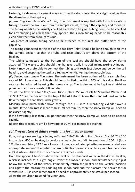
Note slight sideways movement may occur, as the slot is intentionally slightly wider than the diameter of the capillary. (ii) Inserting 2 mm bore silicon tubing. The instrument is supplied with 2 mm bore silicon tubing to carry the emulsion from the sample vessel, through the capillary and to waste. The tubing needs to be visually checked each day. The glass tubing needs to be checked for any chipping or cracks that may appear. The silicon tubing needs to be reasonably clean and free from product residue. Two pieces of silicon tubing need to be attached to the inlet and outlet sides of the capillary. The tubing connected to the top of the capillary (inlet) should be long enough to fit into the sample beaker, so that the tube end rests about 1 cm above the bottom of the beaker. The tubing connected to the bottom of the capillary should have the screw clamp attached. This waste tubing should then hang vertically into a 25 ml measuring cylinder. Note It may be preferable to connect the tubing so it rests just above and below the cell head to avoid snapping the capillary tubing when tightening the movable jaw. (iii) Setting the sample flow rates. The instrument has been optimised for a sample flow rate of 10 ml per minute. This should be controlled to within ±10% of this value. The flow rate can be adjusted by using the screw clamp. The tubing must be kept as straight as possible to ensure a constant flow rate. To set the flow rate for 1% v/v emulsions, place 250 ml of CIPAC Standard Water D at 30 °C ± 2 °C in the beaker on the top of the AET stand. Allow the standard hard water to flow through the capillary under gravity. Measure how much water flows through the AET into a measuring cylinder over 1 minute. If the flow rate is more than 11 ml per minute, then the screw clamp will need to be closed slightly. If the flow rate is less than 9 ml per minute then the screw clamp will need to be opened slightly. Repeat this procedure until a flow rate of 10 ml per minute is obtained.
(c) Preparation of dilute emulsions for measurement
Pour, using a measuring cylinder, sufficient CIPAC Standard Hard Water D at 30 °C ± 2 °C into a clean 400 ml beaker, to produce a final volume of dilute emulsion of 250 ml (for a 1% dilute emulsion, 247.5 ml of water). Using a graduated pipette, measure carefully an appropriate amount of emulsion or emulsifiable concentrate on to a clean teaspoon (for a 1% dilute emulsion 2.5 ml of concentrate is measured). Hold the spoon, 1 to 2 cm above the level of the standard water in the 400 ml beaker, which is inclined at a slight angle. Invert the loaded spoon, and simultaneously dip it below the surface of the water. Immediately return the beaker to the vertical position and agitate the mixture by paddling the spoon back and forth across the beaker for 20 strokes (i.e. 10 in each direction) at a speed of approximately one stroke per second. Allow the emulsion to stand for 2 minutes.
Authorised copy of CIPAC Handbook J
15
Repeat the paddling for a further 20 strokes as above.
(d) Obtaining an AET reading for a dilute emulsion
Immediately place the beaker on top of the laboratory jack which is situated on the shelf behind the AET. Immerse the tubing into the beaker so that the tube end rests about 1 cm above the bottom of the beaker. Place the waste tubing vertically into a waste beaker and allow the sample to flow through the capillary under gravity at the fixed flow rate of 10 ml per minute. When a steady reading is obtained on the display (within 20 seconds of preparing the emulsion), record the AC value. Remove the tubing from the emulsion and repeat the process after 5, 10, 15 and 30 minute intervals to get an indication of time dependence. The resultant values will provide an indication of emulsion stability over time. Similar readings over 30 minutes, coupled with a low initial AC value (generally <1) will indicate good stability. Conversely, readings which vary over 30 minutes, and where the initial reading is high (generally ≥ 1) will indicate poor stability. Where emulsion stability is checked with time, it is recommended that the beaker containing the emulsion is returned to a water bath maintained at 30 °C ± 2 °C after each reading has been taken. When complete, clean the tubing and capillary by replacing the sample beaker with a beaker containing clean standard hard water. Allow this to flush through the system into the waste beaker. The glass and silicon tubing will be clean when a reading of less than 0.05 is attained.
Note 1 Other rates down to 0.1% have also been tested successfully, but would need to be checked for specific applications
Note 2 Obtainable from: Rank Brothers Ltd 56 High Street, Bottisham, Cambridge, CB25 9DA England Telephone: +44 (0)1223 811369 Fax: +44 (0)1223 811441 E-mail: [email protected] Website: www.rankbrothers.co.uk
Authorised copy of CIPAC Handbook J
16
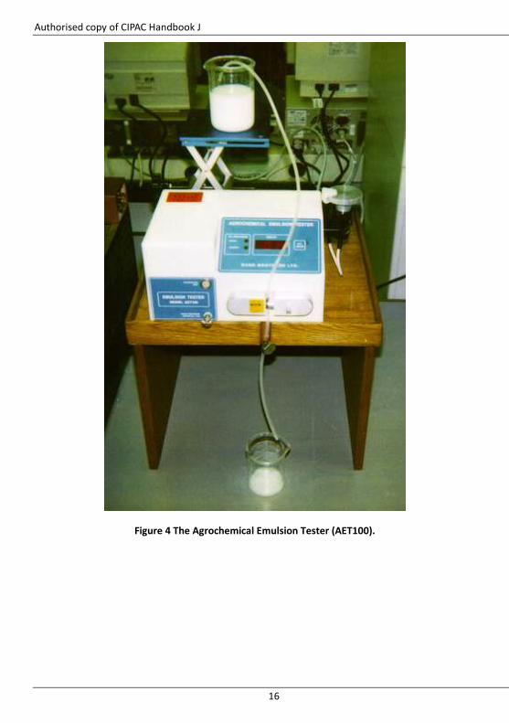
Figure 4 The Agrochemical Emulsion Tester (AET100).
Authorised copy of CIPAC Handbook J
17
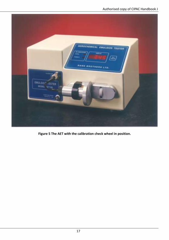
Figure 5 The AET with the calibration check wheel in position.