Embed Size (px)
Citation preview
AgilentHSDPA RF Measurements for User Equipment
Application Note
2
Introduction . . . . . . . . . . . . . . . . . . . . . . . . . . . . . . . . . . . . . . . . . . . . . . . . . . . . . . . . . . . . . . . .3
Why Test HSDPA User Equipment? . . . . . . . . . . . . . . . . . . . . . . . . . . . . . . . . . . . . . . . . . . . .4
HSDPA UE RF Conformance Tests . . . . . . . . . . . . . . . . . . . . . . . . . . . . . . . . . . . . . . . . . . . . .10
General Test Configuration and Metrics . . . . . . . . . . . . . . . . . . . . . . . . . . . . . . . . . . . . . . .10
HSDPA Transmitter Conformance Tests(3GPP TS 34.121 Sections 5.2A, 5.7A, 5.9A, 5.10A, and 5.13.1A) . . . . . . . . . . . . . . . . .15
HSDPA Receiver Conformance Test (3GPP TS 34.121 Section 6.3A) . . . . . . . . . . . . . . . .23
HSDPA Performance Requirement Tests . . . . . . . . . . . . . . . . . . . . . . . . . . . . . . . . . . . . . . .25Demodulation of HS-DSCH (3GPP TS 34.121 Section 9.2) . . . . . . . . . . . . . . . . . . . . . . .27Reporting of CQI (3GPP TS 34.121 Section 9.3) . . . . . . . . . . . . . . . . . . . . . . . . . . . . . . . .35HS-SCCH Detection Performance (3GPP TS 34.121 Section 9.4) . . . . . . . . . . . . . . . . . .45
Agilent HSDPA Solutions . . . . . . . . . . . . . . . . . . . . . . . . . . . . . . . . . . . . . . . . . . . . . . . . . . . .48
Summary . . . . . . . . . . . . . . . . . . . . . . . . . . . . . . . . . . . . . . . . . . . . . . . . . . . . . . . . . . . . . . . . .57
Appendix . . . . . . . . . . . . . . . . . . . . . . . . . . . . . . . . . . . . . . . . . . . . . . . . . . . . . . . . . . . . . . . . .58
Acronym Glossary . . . . . . . . . . . . . . . . . . . . . . . . . . . . . . . . . . . . . . . . . . . . . . . . . . . . . . . . . .61
Reference Specification Documents . . . . . . . . . . . . . . . . . . . . . . . . . . . . . . . . . . . . . . . . . .62
Additional References . . . . . . . . . . . . . . . . . . . . . . . . . . . . . . . . . . . . . . . . . . . . . . . . . . . . . .63
Related Information . . . . . . . . . . . . . . . . . . . . . . . . . . . . . . . . . . . . . . . . . . . . . . . . . . . . . . . .63
Table of Contents
3
High speed downlink packet access (HSDPA) is a new packet-based service in the ThirdGeneration Partnership Project (3GPP) Wideband-Code Division Multiple Access (W-CDMA)radio format. Designed to provide higher data throughput on the downlink, it was firstintroduced in Release 5 of the 3GPP specifications. HSDPA employs adaptive modulationand coding to continually reconfigure the downlink, optimizing data throughput for eachuser depending on the instantaneous quality of the link. The new service is backwards-compatible with 3GPP Release 99 and can be used in conjunction with other services tothe same user equipment (UE). Voice and data applications developed for W-CDMARelease 99 can still be run on the upgraded Release 5 networks, and the same radio channel will support W-CDMA and HSDPA services simultaneously.
The changes that HSDPA introduces have test implications in many different areas,including the radio frequency (RF). New UE transmitter and receiver characteristic requirements and a whole new section for UE HSDPA performance requirements havebeen added to the Release 5 and Release 6 RF conformance test specifications.
This application note explains the meaning and the purpose of the new RF conformancetests for HSDPA-capable UE. The test solutions from Agilent for the different stages ofHSDPA UE research and development (R&D) and manufacturing are also introduced.
To get the most from this application note, you should have knowledge of the basic concepts of HSDPA technology. This information is available in the application note“Concepts of High Speed Downlink Packet Access: Bringing Increased Throughput andEfficiency to W-CDMA” (literature number 5989-2365EN). You also should have a goodunderstanding of W-CDMA concepts and measurements.
Please note that a complete listing of the 3GPP specifications mentioned in this applicationnote is provided in the Reference Specification Documents section of this note. Other references that appear in brackets [] are listed in the section Other References.
Introduction
4
Although HSDPA is primarily a baseband or signaling extension to W-CDMA, manyaspects of the new service require specialized testing.
The main aspects of HSDPA technology that have implications for physical layer testingof the UE are the following:
• The new uplink high speed dedicated physical control channel (HS-DPCCH)increases the peak-to-average power ratio (PAR).
• The uplink HS-DPCCH is not usually transmitted continuously and can be offset intime from the dedicated physical control channel (DPCCH).
• The new 16QAM format in the downlink high speed physical data shared channel(HS-PDSCH) has less margin for UE receiver impairments than does QPSK.
• Decoding the downlink high speed data shared channel (HS-DSCH) involvescomplex new functionality.
• Accurate channel quality reporting is crucial to overall system performance.
• Without correct detection of the high speed shared control channel (HS-SCCH)downlink control information, HSDPA communication is not possible.
Each of these areas of change and the implications for testing are next discussed briefly.
HS-DPCCH increases uplink peak-to-average power ratio (PAR)
The biggest change on the uplink is the addition of the high speed dedicated physicalcontrol channel (HS-DPCCH).
The standard Release 99 W-CDMA uplink signal, which consists of the dedicated physicaldata channel (DPDCH) and the DPCCH, can have a peak-to-average power ratio (PAR) at0.1% from about 3.1 dB to about 3.6 dB, depending on the signal configuration. The newcode channel (HS-DPCCH) can add up to ~1 dB to the PAR (at 0.1%) of the uplink signal [1].
Because the HS-DPCCH is not usually transmitted continuously, the PAR increases onlywhen the acknowledgement/negative acknowledgement (ACK/NACK) or the channelquality indicator (CQI) fields are transmitted. The exact increase in the PAR depends onthe beta factors ßc, ßd, and ßhs, which correspond to the relative power levels of theuplink DPCCH, DPDCH, and HS-DPCCH.
A higher PAR can increase the distortion generated by the transmitter, and particularly bythe power amplifier, resulting in higher out-of-channel interference and poorer modulationquality. So that Release 99 power amplifiers will work correctly with this higher PAR signal,the maximum output power requirement is reduced when the HS-DPCCH is on.
Why Test HSDPA User Equipment?
5
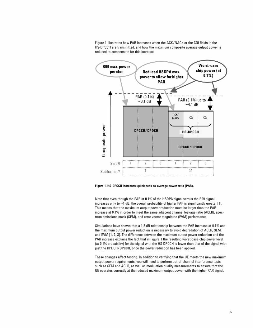
Figure 1 illustrates how PAR increases when the ACK/NACK or the CQI fields in the HS-DPCCH are transmitted, and how the maximum composite average output power isreduced to compensate for this increase.
Figure 1. HS-DPCCH increases uplink peak-to-average power ratio (PAR).
Note that even though the PAR at 0.1% of the HSDPA signal versus the R99 signalincreases only to ~1 dB, the overall probability of higher PAR is significantly greater [1].This means that the maximum output power reduction must be larger than the PARincrease at 0.1% in order to meet the same adjacent channel leakage ratio (ACLR), spec-trum emissions mask (SEM), and error vector magnitude (EVM) performance.
Simulations have shown that a 1:2 dB relationship between the PAR increase at 0.1% andthe maximum output power reduction is necessary to avoid degradation of ACLR, SEM,and EVM [1, 2, 3]. The difference between the maximum output power reduction and thePAR increase explains the fact that in Figure 1 the resulting worst-case chip power level(at 0.1% probability) for the signal with the HS-DPCCH is lower than that of the signal withjust the DPDCH/DPCCH, once the power reduction has been applied.
These changes affect testing. In addition to verifying that the UE meets the new maximumoutput power requirements, you will need to perform out-of-channel interference tests,such as SEM and ACLR, as well as modulation quality measurements to ensure that theUE operates correctly at the reduced maximum output power with the higher PAR signal.
6
The uplink HS-DPCCH is not usually transmitted continuously andcan be offset in time from the DPCCH
As noted earlier, the HS-DPCCH is not usually transmitted continuously and can be offsetin time from the DPCCH. Turning the HS-DPCCH on and off can cause power steps of upto 7 dB, depending on the beta factors.
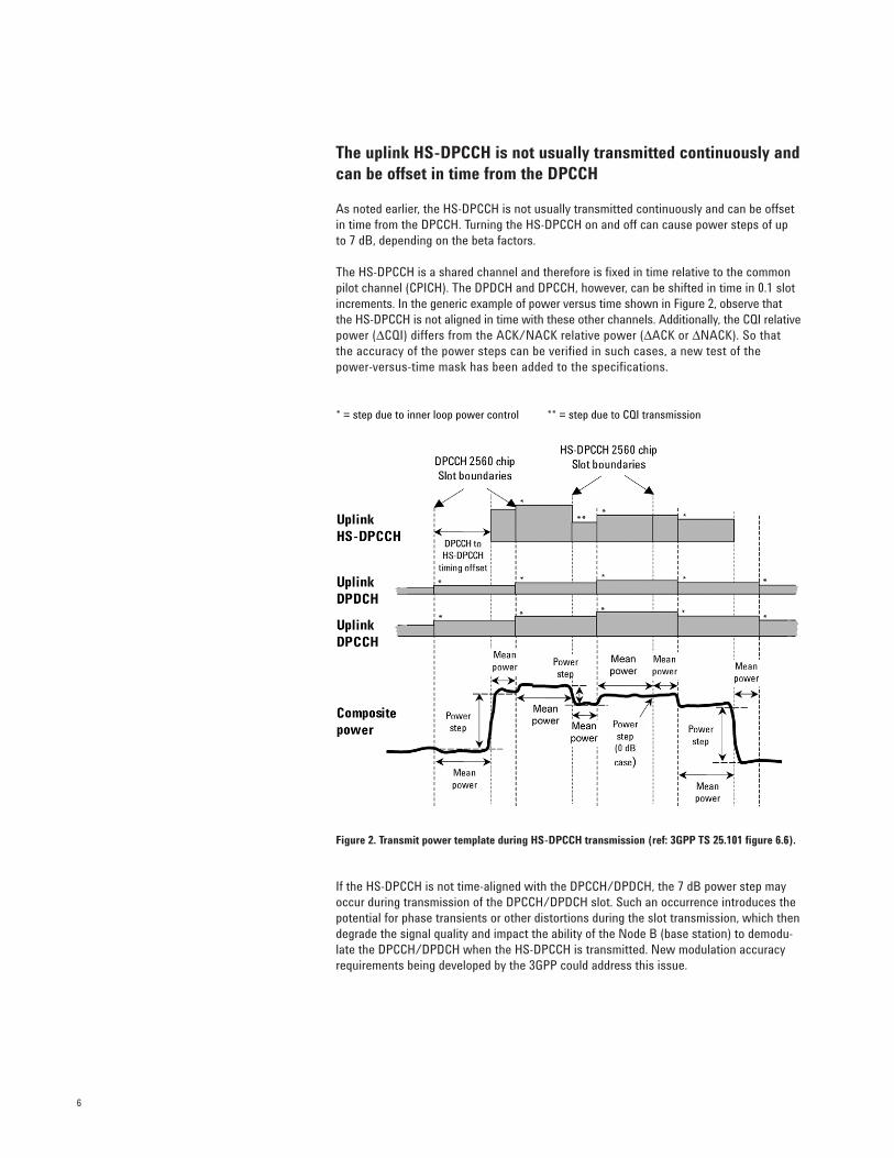
The HS-DPCCH is a shared channel and therefore is fixed in time relative to the commonpilot channel (CPICH). The DPDCH and DPCCH, however, can be shifted in time in 0.1 slotincrements. In the generic example of power versus time shown in Figure 2, observe thatthe HS-DPCCH is not aligned in time with these other channels. Additionally, the CQI relativepower (∆CQI) differs from the ACK/NACK relative power (∆ACK or ∆NACK). So that the accuracy of the power steps can be verified in such cases, a new test of the power-versus-time mask has been added to the specifications.
Figure 2. Transmit power template during HS-DPCCH transmission (ref: 3GPP TS 25.101 figure 6.6).
If the HS-DPCCH is not time-aligned with the DPCCH/DPDCH, the 7 dB power step mayoccur during transmission of the DPCCH/DPDCH slot. Such an occurrence introduces thepotential for phase transients or other distortions during the slot transmission, which thendegrade the signal quality and impact the ability of the Node B (base station) to demodu-late the DPCCH/DPDCH when the HS-DPCCH is transmitted. New modulation accuracyrequirements being developed by the 3GPP could address this issue.
* = step due to inner loop power control ** = step due to CQI transmission
7
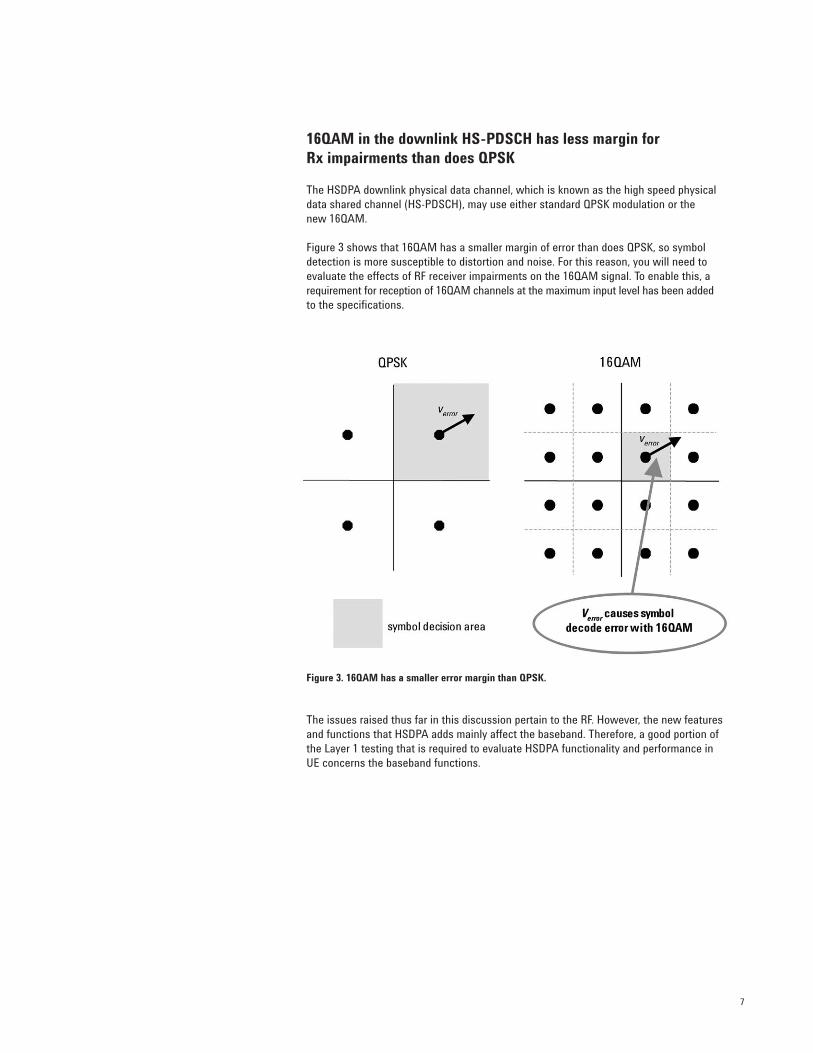
16QAM in the downlink HS-PDSCH has less margin for Rx impairments than does QPSK
The HSDPA downlink physical data channel, which is known as the high speed physicaldata shared channel (HS-PDSCH), may use either standard QPSK modulation or the new 16QAM.
Figure 3 shows that 16QAM has a smaller margin of error than does QPSK, so symboldetection is more susceptible to distortion and noise. For this reason, you will need toevaluate the effects of RF receiver impairments on the 16QAM signal. To enable this, arequirement for reception of 16QAM channels at the maximum input level has been added to the specifications.
Figure 3. 16QAM has a smaller error margin than QPSK.
The issues raised thus far in this discussion pertain to the RF. However, the new featuresand functions that HSDPA adds mainly affect the baseband. Therefore, a good portion ofthe Layer 1 testing that is required to evaluate HSDPA functionality and performance inUE concerns the baseband functions.
8
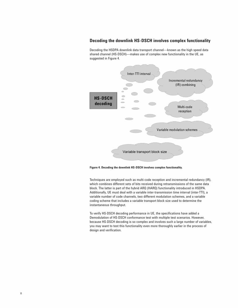
Decoding the downlink HS-DSCH involves complex functionality
Decoding the HSDPA downlink data transport channel—known as the high speed datashared channel (HS-DSCH)—makes use of complex new functionality in the UE, as suggested in Figure 4.
Figure 4. Decoding the downlink HS-DSCH involves complex functionality.
Techniques are employed such as multi-code reception and incremental redundancy (IR),which combines different sets of bits received during retransmissions of the same datablock. The latter is part of the hybrid ARQ (HARQ) functionality introduced in HSDPA.Additionally, UE must deal with a variable inter-transmission time interval (inter-TTI), avariable number of code channels, two different modulation schemes, and a variable coding scheme that includes a variable transport block size used to determine the instantaneous throughput.
To verify HS-DSCH decoding performance in UE, the specifications have added aDemodulation of HS-DSCH conformance test with multiple test scenarios. However,because HS-DSCH decoding is so complex and involves such a large number of variables,you may want to test this functionality even more thoroughly earlier in the process ofdesign and verification.
9
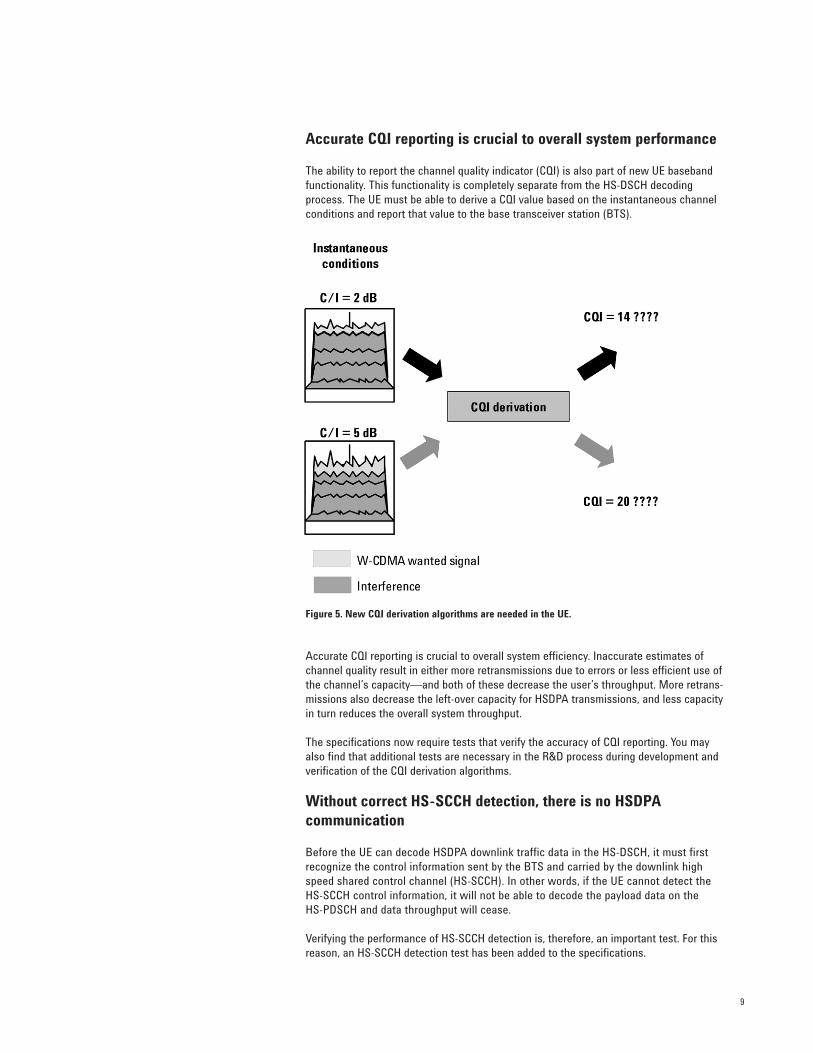
Accurate CQI reporting is crucial to overall system performance
The ability to report the channel quality indicator (CQI) is also part of new UE basebandfunctionality. This functionality is completely separate from the HS-DSCH decodingprocess. The UE must be able to derive a CQI value based on the instantaneous channelconditions and report that value to the base transceiver station (BTS).
Figure 5. New CQI derivation algorithms are needed in the UE.
Accurate CQI reporting is crucial to overall system efficiency. Inaccurate estimates ofchannel quality result in either more retransmissions due to errors or less efficient use ofthe channel’s capacity—and both of these decrease the user’s throughput. More retrans-missions also decrease the left-over capacity for HSDPA transmissions, and less capacityin turn reduces the overall system throughput.
The specifications now require tests that verify the accuracy of CQI reporting. You mayalso find that additional tests are necessary in the R&D process during development andverification of the CQI derivation algorithms.
Without correct HS-SCCH detection, there is no HSDPA communication
Before the UE can decode HSDPA downlink traffic data in the HS-DSCH, it must first recognize the control information sent by the BTS and carried by the downlink highspeed shared control channel (HS-SCCH). In other words, if the UE cannot detect the HS-SCCH control information, it will not be able to decode the payload data on the HS-PDSCH and data throughput will cease.
Verifying the performance of HS-SCCH detection is, therefore, an important test. For thisreason, an HS-SCCH detection test has been added to the specifications.
10
To address the challenges introduced by HSDPA, a number of HSDPA-related tests havebeen added to the UE RF conformance tests (3GPP TS 34.121) in Release 5 and Release 6.Note that there are five new transmitter tests required in 34.121 Section 5:
• Maximum Output Power With HS-DPCCH (34.121 5.2A)• Transmit ON/OFF Power – HS-DPCCH (34.121 5.7A)• SEM (34.121 5.9A)• ACLR (34.121 5.10A) • EVM (34.121 5.13.1A)
One new test of receiver characteristics is required in 34.121 Section 6:
• Maximum Input Level for HS-PDSCH Reception Using 16QAM (34.121 6.3A)
A whole new section, HSDPA Performance Requirements (34.121 Section 9), covers threemain test areas:
• Demodulation of HS-DSCH (34.121 9.2)• Reporting of CQI (34.121 9.3)• HS-SCCH Detection Performance (34.121 9.4)
Before explaining the individual tests in detail, let’s discuss some of the general aspects ofHSDPA conformance testing, focusing on the most common downlink test configurationparameters and metrics.
General downlink test configuration
The downlink test configuration is similar for all the new HSDPA tests (transmitter, receiver,and performance requirements). It consists of the following channels:
• W-CDMA standard channels• orthogonal channel noise simulation (OCNS) channels• HS-DSCH and HS-SCCH
Among the W-CDMA standard channels, the basic W-CDMA control channels—primarycommon pilot channel (P-CPICH), primary common control physical channel (P-CCPCH),synchronization channel (SCH), and paging indicator channel (PICH)—are required toestablish and maintain a connection. A dedicated physical channel (DPCH) is configuredas the downlink 12.2 kbps reference measurement channel (RMC).
Six OCNS channels are transmitted to account for the energy transmitted to other users ina real BTS (see 3GPP TS 34.121 table E.5.5).
Depending on the test, the HS-DSCH configuration is either established as a fixed referencechannel (FRC) or based on a CQI value. Both of these configurations will be described inmore detail later in this application note.
Most of the tests use one HS-SCCH, with the exception of the HS-SCCH detection performance test, which uses four HS-SCCHs.
HSDPA UE RFConformance Tests
General Test Configuration and Metrics
11
It is important to note that all tests are based on a static configuration of the HS-DSCH, soadaptive modulation and coding (AMC) is not used in the system simulator (SS). No testsrely on the direct use of the received CQI report to dynamically configure the downlink HS-DSCH, because specifying UE performance independent of the test system’s behaviorhas proven to be too complicated. Thus the true throughput performance of the UE—thatis, the throughput performance that the UE would achieve in a real HSDPA system withAMC—is not tested.
With the exception of the Demodulation of HS-DSCH test, no tests require HARQ functionality in the SS. In other words, for most tests, the SS sends no retransmissionsbased on the received ACK/NACK report.
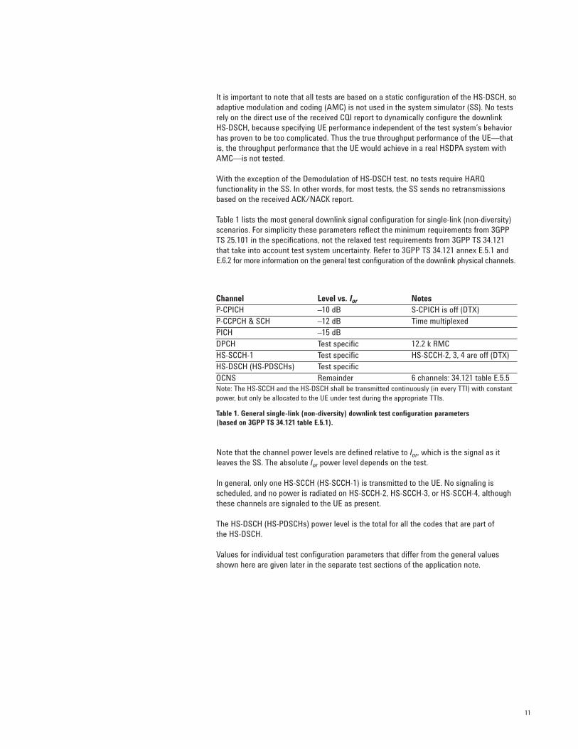
Table 1 lists the most general downlink signal configuration for single-link (non-diversity)scenarios. For simplicity these parameters reflect the minimum requirements from 3GPPTS 25.101 in the specifications, not the relaxed test requirements from 3GPP TS 34.121that take into account test system uncertainty. Refer to 3GPP TS 34.121 annex E.5.1 andE.6.2 for more information on the general test configuration of the downlink physical channels.
Table 1. General single-link (non-diversity) downlink test configuration parameters (based on 3GPP TS 34.121 table E.5.1).
Note that the channel power levels are defined relative to Ior, which is the signal as itleaves the SS. The absolute Ior power level depends on the test.
In general, only one HS-SCCH (HS-SCCH-1) is transmitted to the UE. No signaling isscheduled, and no power is radiated on HS-SCCH-2, HS-SCCH-3, or HS-SCCH-4, althoughthese channels are signaled to the UE as present.
The HS-DSCH (HS-PDSCHs) power level is the total for all the codes that are part of the HS-DSCH.
Values for individual test configuration parameters that differ from the general valuesshown here are given later in the separate test sections of the application note.
Channel Level vs. Ior NotesP-CPICH –10 dB S-CPICH is off (DTX)P-CCPCH & SCH –12 dB Time multiplexedPICH –15 dBDPCH Test specific 12.2 k RMCHS-SCCH-1 Test specific HS-SCCH-2, 3, 4 are off (DTX)HS-DSCH (HS-PDSCHs) Test specificOCNS Remainder 6 channels: 34.121 table E.5.5Note: The HS-SCCH and the HS-DSCH shall be transmitted continuously (in every TTI) with constantpower, but only be allocated to the UE under test during the appropriate TTIs.
12
Fixed reference channels
Fixed reference channel H-Sets (FRC H-Sets) are the HSDPA equivalent of the referencemeasurement channels (RMC) used for W-CDMA. The FRC H-Sets define the HS-DSCHconfigurations most often used for HSDPA conformance testing.
The term “fixed” refers to the static nature of the modulation and coding of these channels.As indicated earlier, AMC is not used because of the difficulty in isolating the performanceof the SS from that of the UE.
There are five FRC H-Sets (FRC H-Set 1 to 5) defined in Release 5. Another FRC H-Set(FRC H-Set 6) has been added in Release 6. For some of the tests, such as Demodulationof HS-DSCH, the UE category determines which FRC H-Set to use:
• FRC H-Set 1 for UE of HS-DSCH category 1 and 2• FRC H-Set 2 for UE of HS-DSCH category 3 and 4• FRC H-Set 3 for UE of HS-DSCH category 5 and 6• FRC H-Set 4 for UE of HS-DSCH category 11• FRC H-Set 5 for UE of HS-DSCH category 12• RC H-Set 6 (added in Release 6) and FRC H-Set 3 for UE of HS-DSCH category 7 and 8
Performance requirements, and thus FRC, have not yet been defined for UE categories 9and 10. Also, note that FRC H-Sets 1, 2, 3, and 6 each have two configurations, QPSK and16QAM.
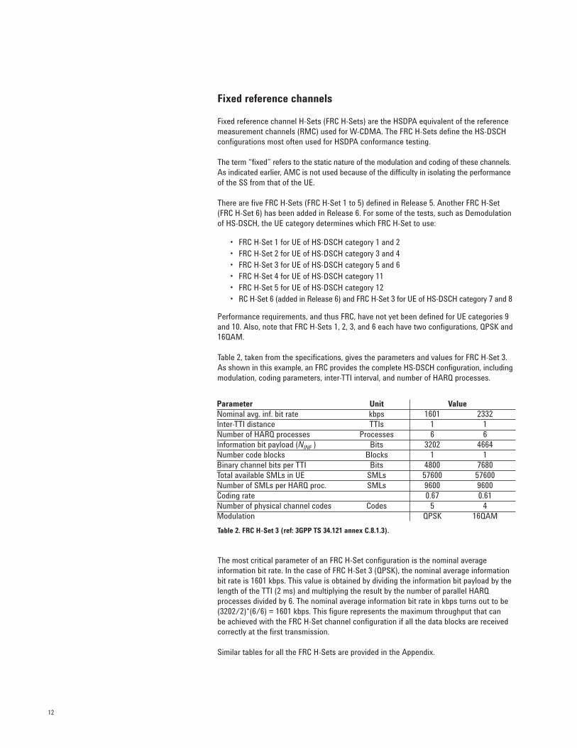
Table 2, taken from the specifications, gives the parameters and values for FRC H-Set 3.As shown in this example, an FRC provides the complete HS-DSCH configuration, includingmodulation, coding parameters, inter-TTI interval, and number of HARQ processes.
Table 2. FRC H-Set 3 (ref: 3GPP TS 34.121 annex C.8.1.3).
The most critical parameter of an FRC H-Set configuration is the nominal average information bit rate. In the case of FRC H-Set 3 (QPSK), the nominal average informationbit rate is 1601 kbps. This value is obtained by dividing the information bit payload by thelength of the TTI (2 ms) and multiplying the result by the number of parallel HARQprocesses divided by 6. The nominal average information bit rate in kbps turns out to be(3202/2)*(6/6) = 1601 kbps. This figure represents the maximum throughput that can be achieved with the FRC H-Set channel configuration if all the data blocks are receivedcorrectly at the first transmission.
Similar tables for all the FRC H-Sets are provided in the Appendix.
Parameter Unit ValueNominal avg. inf. bit rate kbps 1601 2332Inter-TTI distance TTIs 1 1Number of HARQ processes Processes 6 6Information bit payload (NINF ) Bits 3202 4664Number code blocks Blocks 1 1Binary channel bits per TTI Bits 4800 7680Total available SMLs in UE SMLs 57600 57600Number of SMLs per HARQ proc. SMLs 9600 9600Coding rate 0.67 0.61Number of physical channel codes Codes 5 4Modulation QPSK 16QAM
13
Relationship between t-put R and BLER
The most common metrics used in HSDPA receiver and performance requirement testingare throughput rate (t-put R) and block error rate (BLER).
Because HSDPA is an asymmetric service, you cannot loop the payload data back on the uplink for bit error rate (BER) analysis in the test system. The only data that can be“looped back” are the ACK/NACK and CQI data. Thus the only way to measure BER is toextract the payload data directly from the UE. Although BER is not an HSDPA conformancerequirement, it can be useful in R&D as a sensitive measure of receiver performance.
Most HSPDA receiver and performance tests instead specify the minimum requirementsin terms of information bit t-put R, which is calculated from the ACK/NACK report and isrelated to BLER.
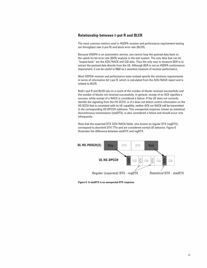
Both t-put R and BLER rely on a count of the number of blocks received successfully andthe number of blocks not received successfully. In general, receipt of an ACK signifies asuccess, while receipt of a NACK is considered a failure. If the UE does not correctlyidentify the signaling from the HS-SCCH, or if it does not detect control information on theHS-SCCH that is consistent with its UE capability, neither ACK nor NACK will be transmittedin the corresponding HS-DPCCH subframe. This unexpected response, known as statisticaldiscontinuous transmission (statDTX), is also considered a failure and should occur onlyinfrequently.
Note that the expected DTX ACK/NACK fields, also known as regular DTX (regDTX), correspond to downlink DTX TTIs and are considered normal UE behavior. Figure 6 illustrates the difference between statDTX and regDTX.
Figure 6. A statDTX is an unexpected DTX response.
DL HS-PDSCH(S)
UL HS-DPCCH
Regular (expected) DTX - regDTX Statistical DTX - statDTX
DTX DTX
CQI CQI CQI CQI
DataData
ACK
DTX
DTX
DTX
14
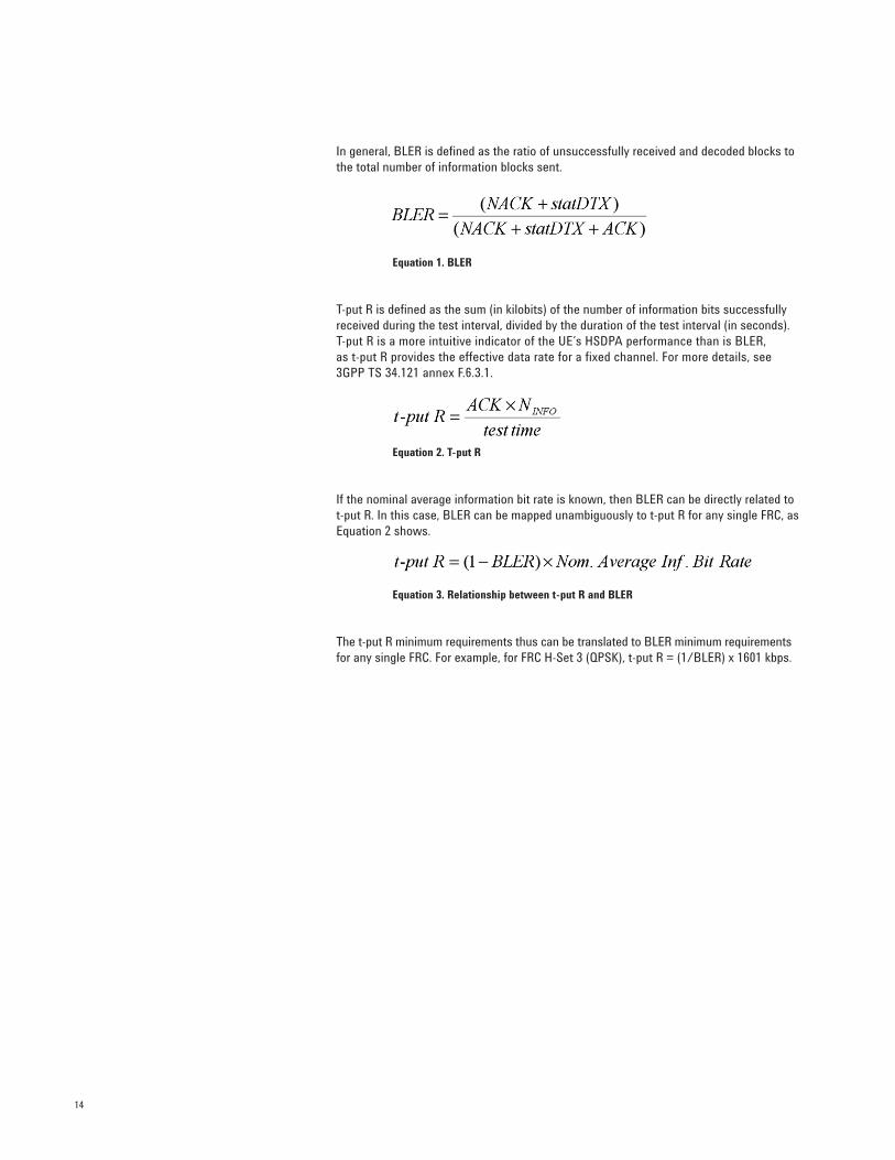
In general, BLER is defined as the ratio of unsuccessfully received and decoded blocks tothe total number of information blocks sent.
Equation 1. BLER
T-put R is defined as the sum (in kilobits) of the number of information bits successfullyreceived during the test interval, divided by the duration of the test interval (in seconds).T-put R is a more intuitive indicator of the UE’s HSDPA performance than is BLER, as t-put R provides the effective data rate for a fixed channel. For more details, see 3GPP TS 34.121 annex F.6.3.1.
Equation 2. T-put R
If the nominal average information bit rate is known, then BLER can be directly related tot-put R. In this case, BLER can be mapped unambiguously to t-put R for any single FRC, asEquation 2 shows.
Equation 3. Relationship between t-put R and BLER
The t-put R minimum requirements thus can be translated to BLER minimum requirementsfor any single FRC. For example, for FRC H-Set 3 (QPSK), t-put R = (1/BLER) x 1601 kbps.
15
Several tests of the transmitter characteristics have been added in the specifications to account for the addition of the HS-DPCCH in the uplink:
• Maximum Output Power with HS-DPCCH (34.121 5.2A)• Transmit On/Off Power – HS-DPCCH (34.121 5.7A)• SEM with HS-DPCCH (34.121 5.9A)• ACLR with HS-DPCCH (34.121 5.10A)• EVM with HS-DPCCH (34.121 5.13.1A)
The new HSDPA transmitter tests are mainly variations of R99 W-CDMA tests and areused to verify whether the transmitter can handle the addition of the uplink HS-DPCCH.Recall that the HS-DPCCH increases the PAR of the uplink signal, is not transmitted continuously in most cases, and can be offset in time from the DPCCH. These aspects of the HS-DPCCH pose some challenges for the transmitter.
The following HSDPA transmitter conformance tests must therefore be performed with the HS-DPCCH:
• Maximum Output Power test, similar to the standard R99 W-CDMA Maximum Output Power test, but with relaxed output power requirements to enable continued use of R99 power amplifiers with the higher PAR signal
• New power-versus-time mask to verify the accuracy of the uplink power steps when the bursted HS-DPCCH is transmitted (note that the actual test is called “Transmit On/Off Power – HS-DPCCH” in the specifications)
• SEM test and an ACLR test, similar to the standard R99 W-CDMA SEM and ACLR tests, to verify that the transmitter is operating correctly at the reduced maximum output power with the higher PAR signal
• EVM test to verify that the transmitter is operating correctly at the reduced maximumoutput power with the higher PAR signal. This test should also verify the impact of large HS-DPCCH power steps in the middle of DPCCH/DPDCH slots on the DPCCH/DPDCH signal quality
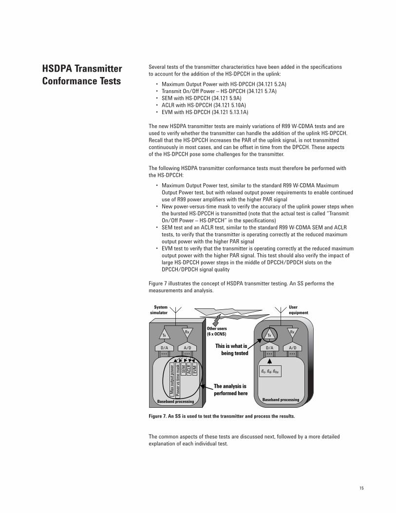
Figure 7 illustrates the concept of HSDPA transmitter testing. An SS performs the measurements and analysis.
Figure 7. An SS is used to test the transmitter and process the results.
The common aspects of these tests are discussed next, followed by a more detailed explanation of each individual test.
HSDPA TransmitterConformance Tests
ßc, ßd, ßhs
Tx
D/A A/D
Rx
Baseband processing
Userequipment
Tx
D/A A/D
Rx
Baseband processing
Systemsimulator
Max
out
put p
ower
Pow
er v
s tim
e m
ask
SEM
ACL
R
EVM
This is what is being tested
Other users(6 x OCNS)
The analysis is performed here
16
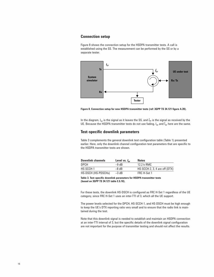
Connection setup
Figure 8 shows the connection setup for the HSDPA transmitter tests. A call is established using the SS. The measurement can be performed by the SS or by a separate tester.
Figure 8. Connection setup for new HSDPA transmitter tests (ref: 3GPP TS 34.121 figure A.20).
In the diagram, Ior is the signal as it leaves the SS, and Îor is the signal as received by theUE. Because the HSDPA transmitter tests do not use fading, Ior and Îor here are the same.
Test-specific downlink parameters
Table 3 complements the general downlink test configuration table (Table 1) presentedearlier. Here, only the downlink channel configuration test parameters that are specific tothe HSDPA transmitter tests are shown.
Table 3. Test-specific downlink parameters for HSDPA transmitter tests (based on 3GPP TS 34.121 table E.5.10).
For these tests, the downlink HS-DSCH is configured as FRC H-Set 1 regardless of the UEcategory, since FRC H-Set 1 uses an inter-TTI of 3, which all the UE support.
The power levels selected for the DPCH, HS-SCCH-1, and HS-DSCH must be high enoughto keep the UE’s DTX reporting ratio very small and to ensure that the radio link is main-tained during the test.
Note that this downlink signal is needed to establish and maintain an HSDPA connectionat an inter-TTI interval of 3, but the specific details of the downlink signal configurationare not important for the purpose of transmitter testing and should not affect the results.
Downlink channels Level vs. Ior NotesDPCH –9 dB 12.2 k RMCHS-SCCH-1 –8 dB HS-SCCH-2, 3, 4 are off (DTX)HS-DSCH (HS-PDSCHs) –3 dB FRC H-Set 1
Systemsimulator
Tx
Rx
Rx/Tx
UE under test
Tester
Ior
Ior
17
Uplink test configuration
All five HSDPA transmitter tests use a similar uplink configuration, which is defined in3GPP TS 34.121 appendix C.10. One of the objectives of the tests is to verify that HSDPAoperation does not interfere with standard operation. For this reason, all the HSDPA testsuse a DPCCH and a DPDCH, configured as a standard uplink 12.2 kbps RMC, in addition tothe HS-DPCCH.
In general, a single HS-DPCCH configuration is chosen for all UE categories to limit thenumber of variables without affecting the results. For example, an inter-TTI interval of 3 isselected because it is supported by all UE categories, even though many are capable ofreceiving blocks more frequently. A 50% (0.5 slot) time offset between the DPCCH and theHS-DPCCH is used for all tests because this time offset is required for some tests, eventhough it is unimportant to others.
The code power ratios between the channels in the uplink test configuration depend onwhich of the six sets of beta factors defined in 3GPP TS 34.121 table C.10.1.4 are used.
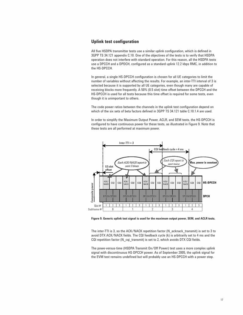
In order to simplify the Maximum Output Power, ACLR, and SEM tests, the HS-DPCCH isconfigured to have continuous power for these tests, as illustrated in Figure 9. Note thatthese tests are all performed at maximum power.
Figure 9. Generic uplink test signal is used for the maximum output power, SEM, and ACLR tests.
The inter-TTI is 3, so the ACK/NACK repetition factor (N_acknack_transmit) is set to 3 toavoid DTX ACK/NACK fields. The CQI feedback cycle (k) is arbitrarily set to 4 ms and theCQI repetition factor (N_cqi_transmit) is set to 2, which avoids DTX CQI fields.
The powe-versus-time (HSDPA Transmit On/Off Power) test uses a more complex uplinksignal with discontinuous HS-DPCCH power. As of September 2005, the uplink signal forthe EVM test remains undefined but will probably use an HS-DPCCH with a power step.
18
Maximum Output Power with HS-DPCCH (34.121 5.2A)
In Release 5 and Release 6, the maximum power specification of the UE transmitter isreduced to allow for the increase in PAR that results from the addition of the HS-DPCCH.
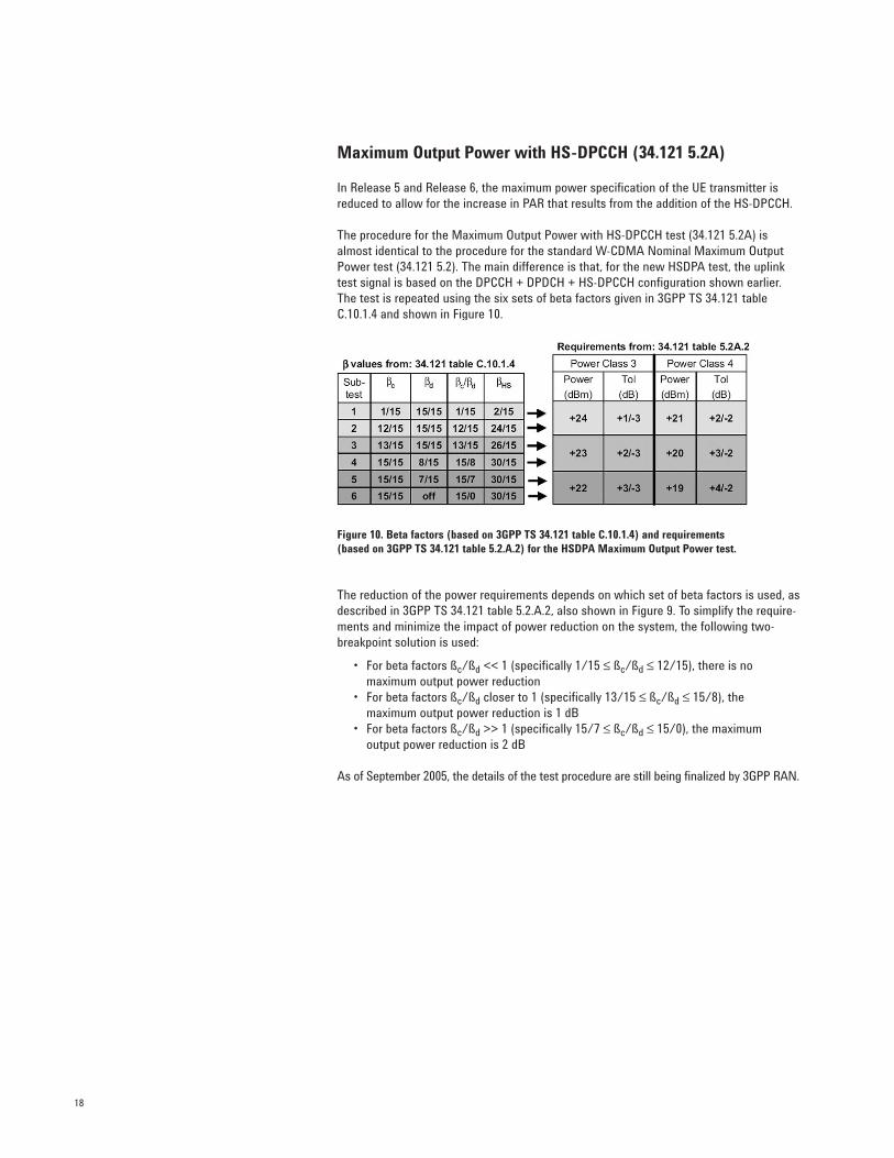
The procedure for the Maximum Output Power with HS-DPCCH test (34.121 5.2A) isalmost identical to the procedure for the standard W-CDMA Nominal Maximum OutputPower test (34.121 5.2). The main difference is that, for the new HSDPA test, the uplinktest signal is based on the DPCCH + DPDCH + HS-DPCCH configuration shown earlier.The test is repeated using the six sets of beta factors given in 3GPP TS 34.121 tableC.10.1.4 and shown in Figure 10.
Figure 10. Beta factors (based on 3GPP TS 34.121 table C.10.1.4) and requirements (based on 3GPP TS 34.121 table 5.2.A.2) for the HSDPA Maximum Output Power test.
The reduction of the power requirements depends on which set of beta factors is used, asdescribed in 3GPP TS 34.121 table 5.2.A.2, also shown in Figure 9. To simplify the require-ments and minimize the impact of power reduction on the system, the following two-breakpoint solution is used:
• For beta factors ßc/ßd << 1 (specifically 1/15 ≤ ßc/ßd ≤ 12/15), there is no maximum output power reduction
• For beta factors ßc/ßd closer to 1 (specifically 13/15 ≤ ßc/ßd ≤ 15/8), the maximum output power reduction is 1 dB
• For beta factors ßc/ßd >> 1 (specifically 15/7 ≤ ßc/ßd ≤ 15/0), the maximum output power reduction is 2 dB
As of September 2005, the details of the test procedure are still being finalized by 3GPP RAN.
19
Transmit On/Off Power – HS-DPCCH (34.121 5.7A)
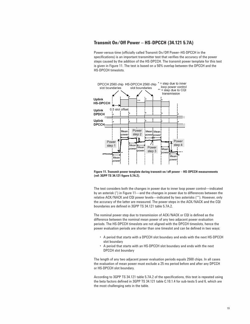
Power-versus-time (officially called Transmit On/Off Power–HS-DPCCH in the specifications) is an important transmitter test that verifies the accuracy of the powersteps caused by the addition of the HS-DPCCH. The transmit power template for this testis given in Figure 11. The test is based on a 50% overlap between the DPCCH and the HS-DPCCH timeslots.
Figure 11. Transmit power template during transmit on/off power – HS-DPCCH measurements(ref: 3GPP TS 34.121 figure 5.7A.2).
The test considers both the changes in power due to inner loop power control—indicatedby an asterisk (*) in Figure 11—and the changes in power due to differences between therelative ACK/NACK and CQI power levels—indicated by two asterisks (**). However, onlythe accuracy of the latter are measured. The power steps in the ACK/NACK and the CQIboundaries are defined in 3GPP TS 34.121 table 5.7A.2.
The nominal power step due to transmission of ACK/NACK or CQI is defined as the difference between the nominal mean power of any two adjacent power evaluation periods. The HS-DPCCH timeslots are not aligned with the DPCCH timeslots, hence thepower evaluation periods are shorter than one timeslot and can be defined in two ways:
• A period that starts with a DPCCH slot boundary and ends with the next HS-DPCCHslot boundary
• A period that starts with an HS-DPCCH slot boundary and ends with the next DPCCH slot boundary
The length of any two adjacent power evaluation periods equals 2560 chips. In all casesthe evaluation of mean power must exclude a 25 ms period before and after any DPCCH or HS-DPCCH slot boundary.
According to 3GPP TS 34.121 table 5.7A.2 of the specifications, this test is repeated usingthe beta factors defined in 3GPP TS 34.121 table C.10.1.4 for sub-tests 5 and 6, which arethe most challenging sets in the table.
20
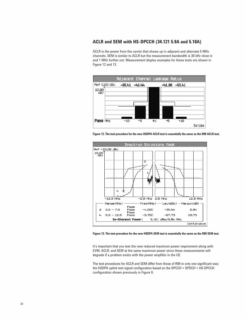
ACLR and SEM with HS-DPCCH (34.121 5.9A and 5.10A)
ACLR is the power from the carrier that shows up in adjacent and alternate 5 MHz channels. SEM is similar to ACLR but the measurement bandwidth is 30 kHz close in and 1 MHz further out. Measurement display examples for these tests are shown inFigure 12 and 13.
Figure 12. The test procedure for the new HSDPA ACLR test is essentially the same as the R99 ACLR test.
Figure 13. The test procedure for the new HSDPA SEM test is essentially the same as the R99 SEM test.
It’s important that you test the new reduced maximum power requirement along withEVM, ACLR, and SEM at the same maximum power since these measurements willdegrade if a problem exists with the power amplifier in the UE.
The test procedures for ACLR and SEM differ from those of R99 in only one significant way:the HSDPA uplink test signal configuration based on the DPCCH + DPDCH + HS-DPCCHconfiguration shown previously in Figure 9.
21
EVM with HS-DPCCH (34.121 5.13.1A) and phase discontinuity
The requirements for EVM and phase discontinuity for uplink transmissions with the HS-DPCCH are still being developed by 3GPP (as of September 2005).
One of the biggest challenges for HSDPA transmitters is to ensure that the UE is transmittingthe DPCCH + DPDCH correctly when the HS-DPCCH turns on or off during the DPCCH slot.A possible source of error is the AM to PM distortion caused by having a 7 dB stepchange in power during a DPCCH slot. If this power step occurs near the UE maximumpower level, distortion of the output phase may result, making demodulation by the BTSvery difficult. The 3GPP is considering a proposal to evaluate how much phase discontinuityis acceptable during the DPCCH/DPDCH slot.
Although the requirement for EVM has not yet been finalized, you can use the existing W-CDMA phase discontinuity measurement to give an indication of whether the perform-ance of a particular UE design is likely to be susceptible to HS-DPCCH power steps.
Under the current W-CDMA requirements, non-HSDPA phase discontinuity is determinedby measuring the change in phase between any two adjacent timeslots. Phase transientsof up to 30 degrees are allowed only at DPCCH/DPDCH slot boundaries. EVM is measuredfor each timeslot, excluding the transient periods of 25 µs on either side of the nominaltimeslot boundaries. The frequency, absolute phase, absolute amplitude, and chip clocktiming used to minimize the error vector are chosen independently for each timeslot. Thephase discontinuity result is defined as the difference between the absolute phase usedto calculate EVM for the preceding timeslot and the absolute phase used to calculateEVM for the succeeding timeslot.
The existing phase discontinuity requirement applies only for 1 dB changes in powerbetween the slots caused by inner loop power control. However, the power steps causedby HS-DPCCH transmission can be up to 7 dB. Figure 14 shows displays of the phase discontinuity measurement for two UEs with very different output phase performance versus 1 dB power steps.
22
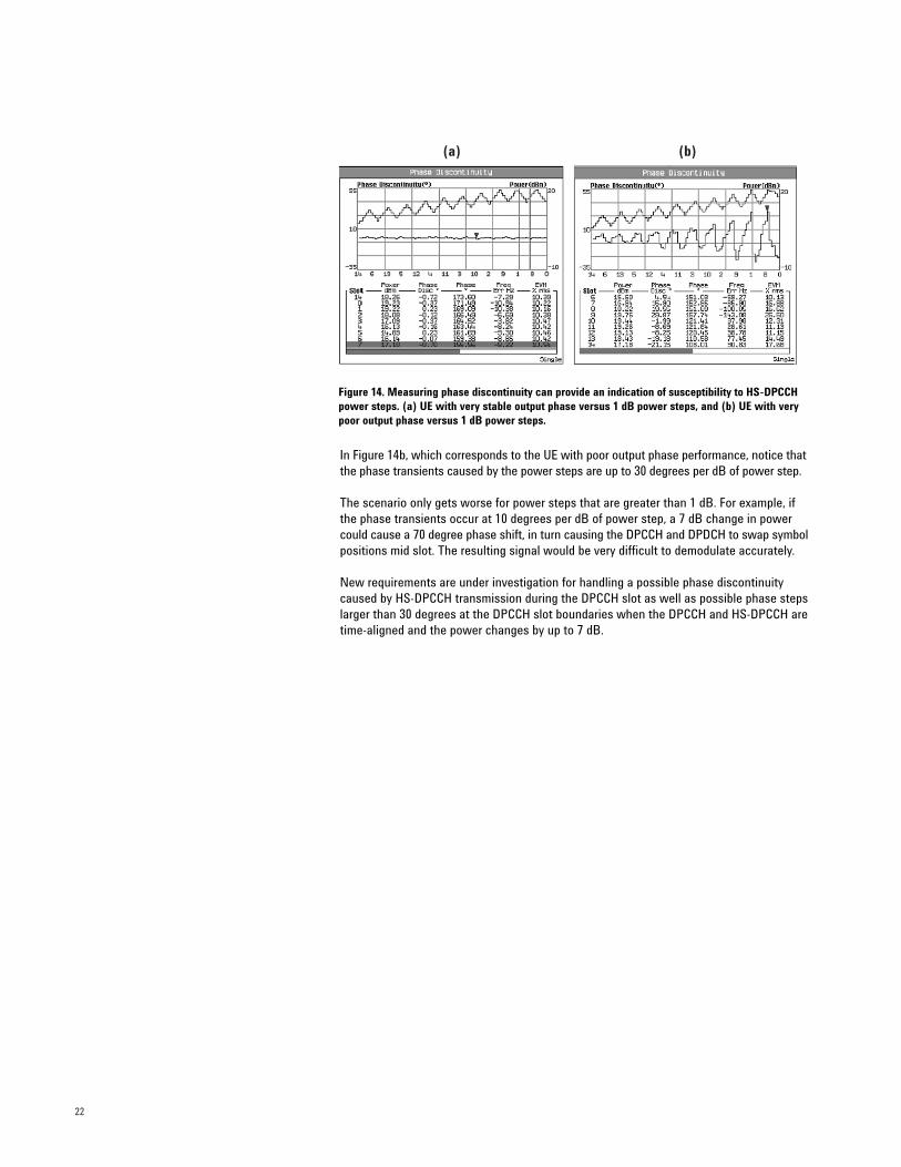
(a) (b)
Figure 14. Measuring phase discontinuity can provide an indication of susceptibility to HS-DPCCHpower steps. (a) UE with very stable output phase versus 1 dB power steps, and (b) UE with verypoor output phase versus 1 dB power steps.
In Figure 14b, which corresponds to the UE with poor output phase performance, notice thatthe phase transients caused by the power steps are up to 30 degrees per dB of power step.
The scenario only gets worse for power steps that are greater than 1 dB. For example, ifthe phase transients occur at 10 degrees per dB of power step, a 7 dB change in powercould cause a 70 degree phase shift, in turn causing the DPCCH and DPDCH to swap symbolpositions mid slot. The resulting signal would be very difficult to demodulate accurately.
New requirements are under investigation for handling a possible phase discontinuitycaused by HS-DPCCH transmission during the DPCCH slot as well as possible phase stepslarger than 30 degrees at the DPCCH slot boundaries when the DPCCH and HS-DPCCH aretime-aligned and the power changes by up to 7 dB.
23
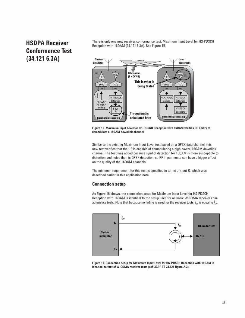
There is only one new receiver conformance test, Maximum Input Level for HS-PDSCHReception with 16QAM (34.121 6.3A). See Figure 15.
Figure 15. Maximum Input Level for HS-PDSCH Reception with 16QAM verifies UE ability todemodulate a 16QAM downlink channel.
Similar to the existing Maximum Input Level test based on a QPSK data channel, this new test verifies that the UE is capable of demodulating a high power, 16QAM downlinkchannel. The test was added because symbol detection for 16QAM is more susceptible todistortion and noise than is QPSK detection, so RF impairments can have a bigger effecton the quality of the 16QAM channels.
The minimum requirement for this test is specified in terms of t-put R, which wasdescribed earlier in this application note.
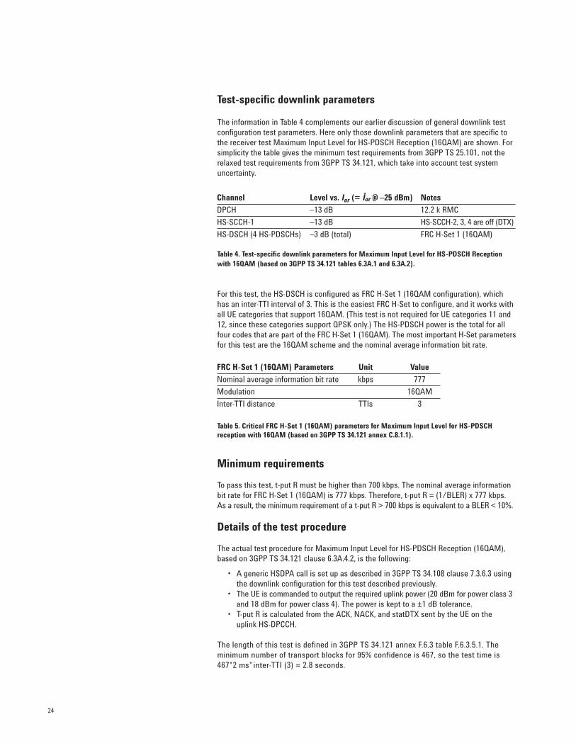
Connection setup
As Figure 16 shows, the connection setup for Maximum Input Level for HS-PDSCHReception with 16QAM is identical to the setup used for all basic W-CDMA receiver char-acteristics tests. Note that because no fading is used for the receiver tests, Ior is equal to Îor.
Figure 16. Connection setup for Maximum Input Level for HS-PDSCH Reception with 16QAM isidentical to that of W-CDMA receiver tests (ref: 3GPP TS 34.121 figure A.3).
HSDPA ReceiverConformance Test(34.121 6.3A)
ACK/NACKcoding
ACK/NACKdetection
HS-SCCHdetection
HS-DSCHdecoding
HS-SCCHHS-DSCH
coding T-putR
Tx
D/A A/D
Rx
Baseband processing
Userequipment
Tx
D/A A/D
Rx
Baseband processing
Systemsimulator
This is what isbeing tested
Other users(6 x OCNS)
Throughput is calculated here
Systemsimulator
Tx
Rx
Rx/Tx
UE under test
Ior
Ior
24
Test-specific downlink parameters
The information in Table 4 complements our earlier discussion of general downlink testconfiguration test parameters. Here only those downlink parameters that are specific tothe receiver test Maximum Input Level for HS-PDSCH Reception (16QAM) are shown. Forsimplicity the table gives the minimum test requirements from 3GPP TS 25.101, not therelaxed test requirements from 3GPP TS 34.121, which take into account test systemuncertainty.
Table 4. Test-specific downlink parameters for Maximum Input Level for HS-PDSCH Receptionwith 16QAM (based on 3GPP TS 34.121 tables 6.3A.1 and 6.3A.2).
For this test, the HS-DSCH is configured as FRC H-Set 1 (16QAM configuration), whichhas an inter-TTI interval of 3. This is the easiest FRC H-Set to configure, and it works withall UE categories that support 16QAM. (This test is not required for UE categories 11 and12, since these categories support QPSK only.) The HS-PDSCH power is the total for allfour codes that are part of the FRC H-Set 1 (16QAM). The most important H-Set parametersfor this test are the 16QAM scheme and the nominal average information bit rate.
Table 5. Critical FRC H-Set 1 (16QAM) parameters for Maximum Input Level for HS-PDSCH reception with 16QAM (based on 3GPP TS 34.121 annex C.8.1.1).
Minimum requirements
To pass this test, t-put R must be higher than 700 kbps. The nominal average informationbit rate for FRC H-Set 1 (16QAM) is 777 kbps. Therefore, t-put R = (1/BLER) x 777 kbps.As a result, the minimum requirement of a t-put R > 700 kbps is equivalent to a BLER < 10%.
Details of the test procedure
The actual test procedure for Maximum Input Level for HS-PDSCH Reception (16QAM),based on 3GPP TS 34.121 clause 6.3A.4.2, is the following:
• A generic HSDPA call is set up as described in 3GPP TS 34.108 clause 7.3.6.3 using the downlink configuration for this test described previously.
• The UE is commanded to output the required uplink power (20 dBm for power class 3and 18 dBm for power class 4). The power is kept to a ±1 dB tolerance.
• T-put R is calculated from the ACK, NACK, and statDTX sent by the UE on the uplink HS-DPCCH.
The length of this test is defined in 3GPP TS 34.121 annex F.6.3 table F.6.3.5.1. The minimum number of transport blocks for 95% confidence is 467, so the test time is 467*2 ms* inter-TTI (3) = 2.8 seconds.
Channel Level vs. Ior (= Îor @ –25 dBm) Notes
DPCH –13 dB 12.2 k RMC
HS-SCCH-1 –13 dB HS-SCCH-2, 3, 4 are off (DTX)
HS-DSCH (4 HS-PDSCHs) –3 dB (total) FRC H-Set 1 (16QAM)
FRC H-Set 1 (16QAM) Parameters Unit Value
Nominal average information bit rate kbps 777
Modulation 16QAM
Inter-TTI distance TTIs 3
25
The specifications define three performance requirements test sections for HSDPA:
• Demodulation of HS-DSCH (34.121 9.2)• Reporting of CQI (34.121 9.3)• HS-SCCH Detection (34.121 9.4)
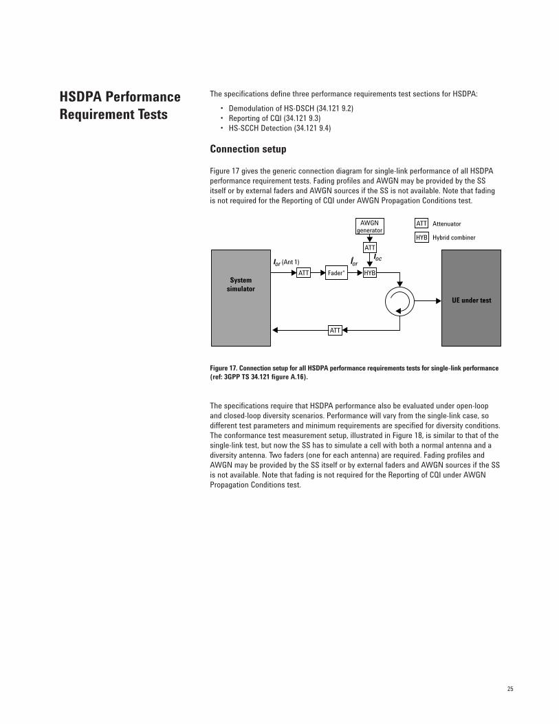
Connection setup
Figure 17 gives the generic connection diagram for single-link performance of all HSDPAperformance requirement tests. Fading profiles and AWGN may be provided by the SSitself or by external faders and AWGN sources if the SS is not available. Note that fadingis not required for the Reporting of CQI under AWGN Propagation Conditions test.
Figure 17. Connection setup for all HSDPA performance requirements tests for single-link performance(ref: 3GPP TS 34.121 figure A.16).
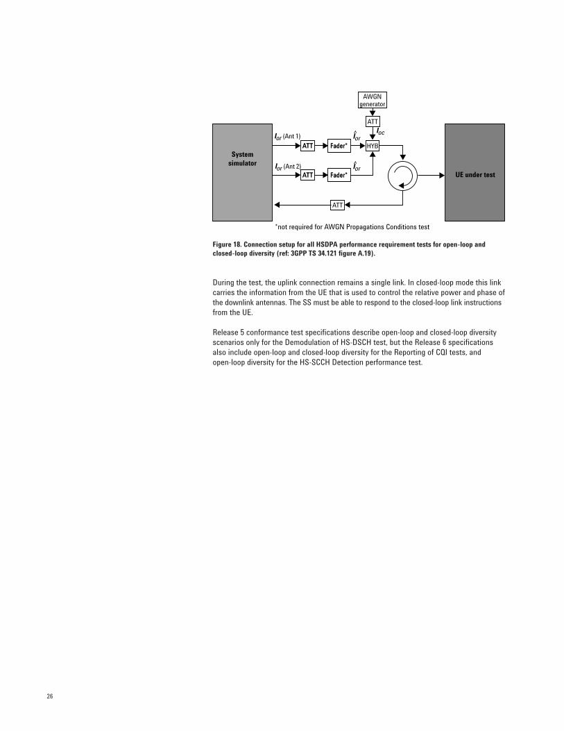
The specifications require that HSDPA performance also be evaluated under open-loopand closed-loop diversity scenarios. Performance will vary from the single-link case, sodifferent test parameters and minimum requirements are specified for diversity conditions.The conformance test measurement setup, illustrated in Figure 18, is similar to that of thesingle-link test, but now the SS has to simulate a cell with both a normal antenna and adiversity antenna. Two faders (one for each antenna) are required. Fading profiles andAWGN may be provided by the SS itself or by external faders and AWGN sources if the SSis not available. Note that fading is not required for the Reporting of CQI under AWGNPropagation Conditions test.
HSDPA PerformanceRequirement Tests
Systemsimulator
UE under test
Ior (Ant 1)IocIor
ATT
ATT
ATT
ATT
HYB
HYB
Fader*
AWGNgenerator
Attenuator
Hybrid combiner
26
Figure 18. Connection setup for all HSDPA performance requirement tests for open-loop andclosed-loop diversity (ref: 3GPP TS 34.121 figure A.19).
During the test, the uplink connection remains a single link. In closed-loop mode this linkcarries the information from the UE that is used to control the relative power and phase ofthe downlink antennas. The SS must be able to respond to the closed-loop link instructionsfrom the UE.
Release 5 conformance test specifications describe open-loop and closed-loop diversityscenarios only for the Demodulation of HS-DSCH test, but the Release 6 specificationsalso include open-loop and closed-loop diversity for the Reporting of CQI tests, and open-loop diversity for the HS-SCCH Detection performance test.
Systemsimulator
UE under test
Ior (Ant 1)Ioc
Ior (Ant 2)
Ior
Ior
ATT Fader*ATT
ATT
ATT
HYBFader*
AWGNgenerator
ATT Fader*ATT Fader*
*not required for AWGN Propagations Conditions test
27
Demodulation of HS-DSCH (34.121 9.2)
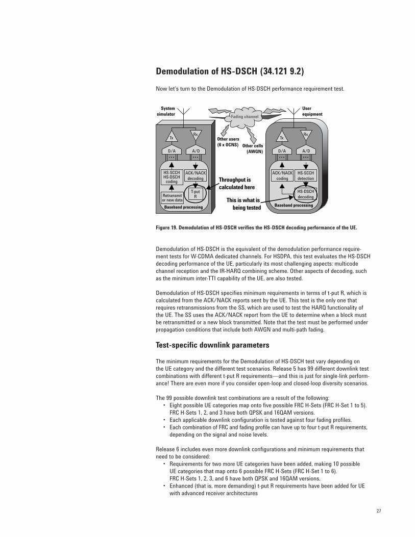
Now let’s turn to the Demodulation of HS-DSCH performance requirement test.
Figure 19. Demodulation of HS-DSCH verifies the HS-DSCH decoding performance of the UE.
Demodulation of HS-DSCH is the equivalent of the demodulation performance require-ment tests for W-CDMA dedicated channels. For HSDPA, this test evaluates the HS-DSCHdecoding performance of the UE, particularly its most challenging aspects: multicodechannel reception and the IR-HARQ combining scheme. Other aspects of decoding, suchas the minimum inter-TTI capability of the UE, are also tested.
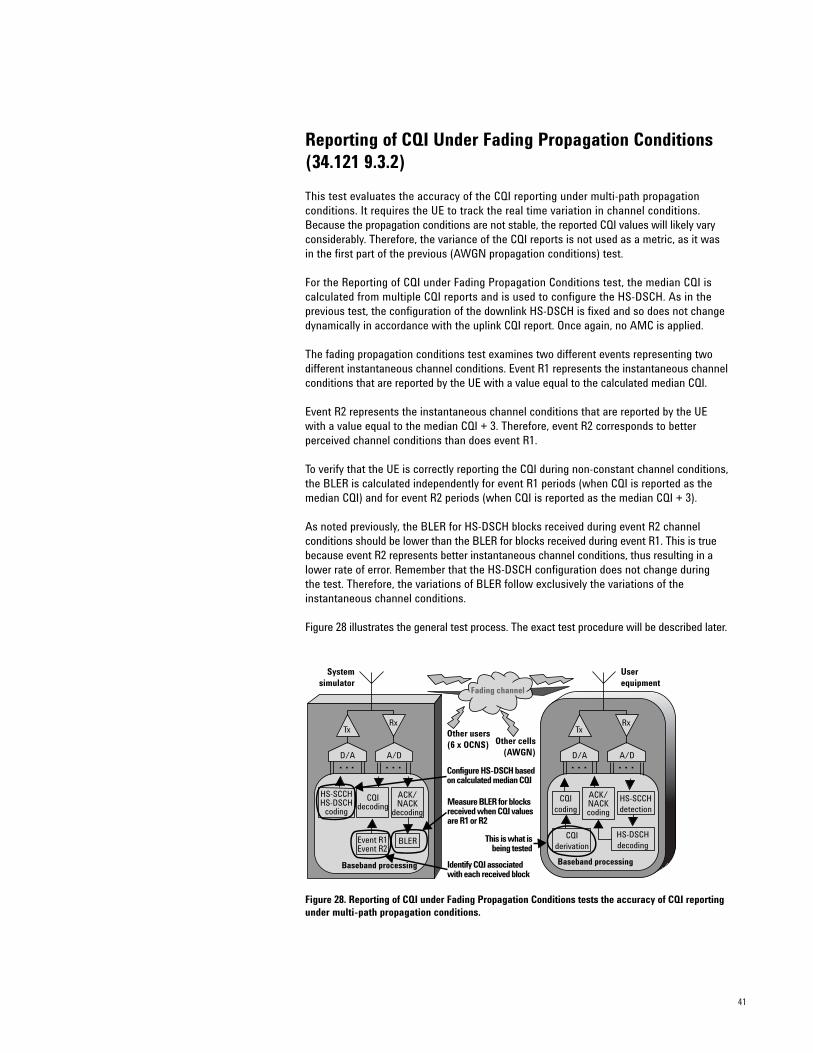
Demodulation of HS-DSCH specifies minimum requirements in terms of t-put R, which iscalculated from the ACK/NACK reports sent by the UE. This test is the only one thatrequires retransmissions from the SS, which are used to test the HARQ functionality ofthe UE. The SS uses the ACK/NACK report from the UE to determine when a block mustbe retransmitted or a new block transmitted. Note that the test must be performed underpropagation conditions that include both AWGN and multi-path fading.
Test-specific downlink parameters
The minimum requirements for the Demodulation of HS-DSCH test vary depending on the UE category and the different test scenarios. Release 5 has 99 different downlink testcombinations with different t-put R requirements—and this is just for single-link perform-ance! There are even more if you consider open-loop and closed-loop diversity scenarios.
The 99 possible downlink test combinations are a result of the following:• Eight possible UE categories map onto five possible FRC H-Sets (FRC H-Set 1 to 5).
FRC H-Sets 1, 2, and 3 have both QPSK and 16QAM versions. • Each applicable downlink configuration is tested against four fading profiles.• Each combination of FRC and fading profile can have up to four t-put R requirements,
depending on the signal and noise levels.
Release 6 includes even more downlink configurations and minimum requirements thatneed to be considered:
• Requirements for two more UE categories have been added, making 10 possible UE categories that map onto 6 possible FRC H-Sets (FRC H-Set 1 to 6). FRC H-Sets 1, 2, 3, and 6 have both QPSK and 16QAM versions.
• Enhanced (that is, more demanding) t-put R requirements have been added for UE with advanced receiver architectures
ACK/NACKcoding
ACK/NACKdecoding
HS-SCCHdetection
HS-DSCHdecoding
HS-SCCHHS-DSCH
coding
Retransmitor new data
T-putR
Fading channel
Other users(6 x OCNS) Other cells
(AWGN)
Tx
D/A A/D
Rx
Baseband processing
Userequipment
Tx
D/A A/D
Rx
Baseband processing
Systemsimulator
This is what is being tested
Throughput is calculated here
28
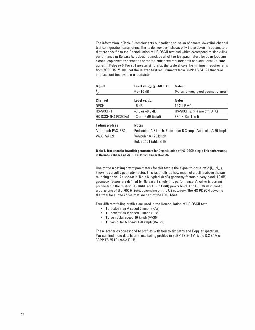
The information in Table 6 complements our earlier discussion of general downlink channeltest configuration parameters. This table, however, shows only those downlink parametersthat are specific to the Demodulation of HS-DSCH test and which correspond to single-linkperformance in Release 5. It does not include all of the test parameters for open-loop andclosed-loop diversity scenarios or for the enhanced requirements and additional UE cate-gories in Release 6. For still greater simplicity, the table shows the minimum requirementsfrom 3GPP TS 25.101, not the relaxed test requirements from 3GPP TS 34.121 that takeinto account test system uncertainty.
Table 6. Test-specific downlink parameters for Demodulation of HS-DSCH single link performancein Release 5 (based on 3GPP TS 34.121 clause 9.2.1.2).
One of the most important parameters for this test is the signal-to-noise ratio (Îor /Ioc),known as a cell’s geometry factor. This ratio tells us how much of a cell is above the sur-rounding noise. As shown in Table 6, typical (0 dB) geometry factors or very good (10 dB)geometry factors are defined for Release 5 single-link performance. Another importantparameter is the relative HS-DSCH (or HS-PDSCH) power level. The HS-DSCH is config-ured as one of the FRC H-Sets, depending on the UE category. The HS-PDSCH power isthe total for all the codes that are part of the FRC H-Set.
Four different fading profiles are used in the Demodulation of HS-DSCH test: • ITU pedestrian A speed 3 kmph (PA3)• ITU pedestrian B speed 3 kmph (PB3)• ITU vehicular speed 30 kmph (VA30)• ITU vehicular A speed 120 kmph (VA120)
These scenarios correspond to profiles with four to six paths and Doppler spectrum. You can find more details on these fading profiles in 3GPP TS 34.121 table D.2.2.1A or3GPP TS 25.101 table B.1B.
Signal Level vs. Ioc @ –60 dBm Notes
Îor 0 or 10 dB Typical or very good geometry factor
Channel Level vs. Ioc Notes
DPCH –5 dB 12.2 k RMC
HS-SCCH-1 –7.5 or –8.5 dB HS-SCCH-2, 3, 4 are off (DTX)
HS-DSCH (HS-PDSCHs) –3 or –6 dB (total) FRC H-Set 1 to 5
Fading profiles Notes
Multi-path PA3, PB3, Pedestrian A 3 kmph, Pedestrian B 3 kmph, Vehicular A 30 kmph,
VA30, VA120 Vehicular A 120 kmph
Ref: 25.101 table B.1B
29
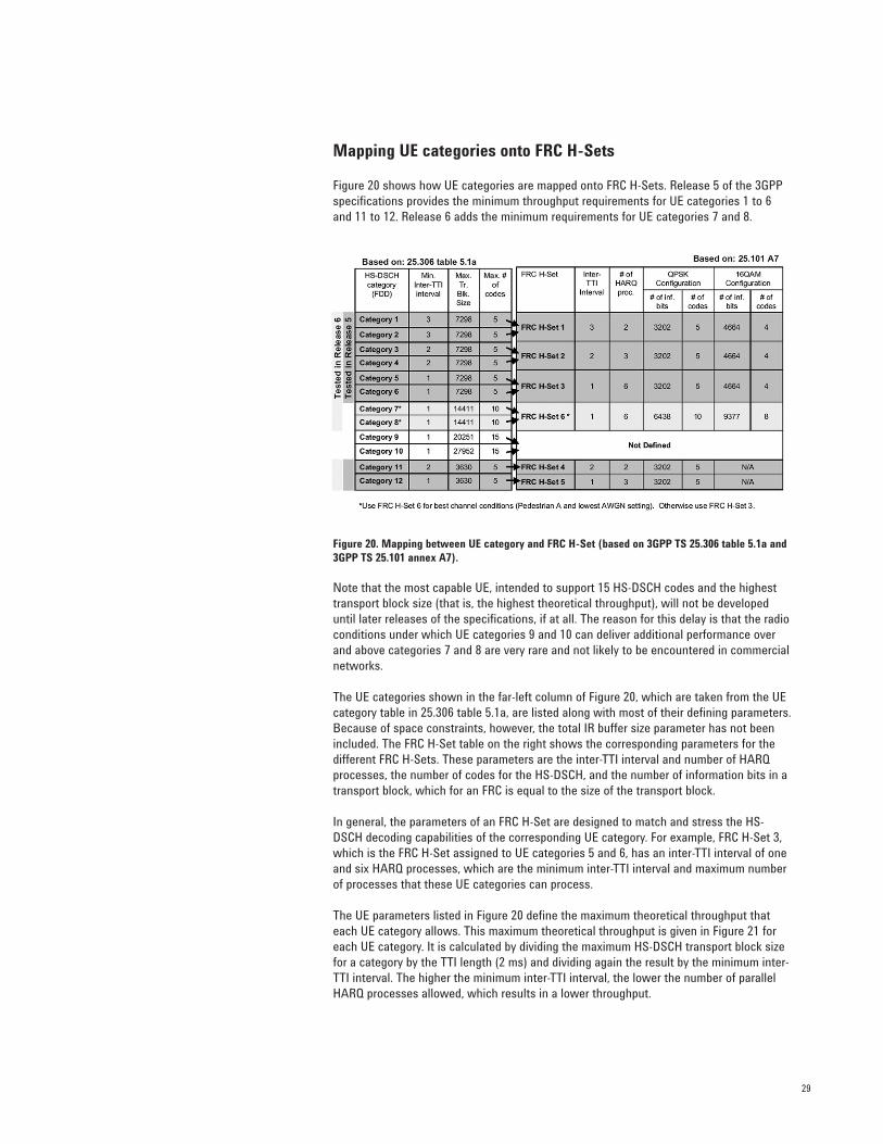
Mapping UE categories onto FRC H-Sets
Figure 20 shows how UE categories are mapped onto FRC H-Sets. Release 5 of the 3GPPspecifications provides the minimum throughput requirements for UE categories 1 to 6and 11 to 12. Release 6 adds the minimum requirements for UE categories 7 and 8.
Figure 20. Mapping between UE category and FRC H-Set (based on 3GPP TS 25.306 table 5.1a and3GPP TS 25.101 annex A7).
Note that the most capable UE, intended to support 15 HS-DSCH codes and the highesttransport block size (that is, the highest theoretical throughput), will not be developeduntil later releases of the specifications, if at all. The reason for this delay is that the radioconditions under which UE categories 9 and 10 can deliver additional performance overand above categories 7 and 8 are very rare and not likely to be encountered in commercialnetworks.
The UE categories shown in the far-left column of Figure 20, which are taken from the UEcategory table in 25.306 table 5.1a, are listed along with most of their defining parameters.Because of space constraints, however, the total IR buffer size parameter has not beenincluded. The FRC H-Set table on the right shows the corresponding parameters for thedifferent FRC H-Sets. These parameters are the inter-TTI interval and number of HARQprocesses, the number of codes for the HS-DSCH, and the number of information bits in atransport block, which for an FRC is equal to the size of the transport block.
In general, the parameters of an FRC H-Set are designed to match and stress the HS-DSCH decoding capabilities of the corresponding UE category. For example, FRC H-Set 3,which is the FRC H-Set assigned to UE categories 5 and 6, has an inter-TTI interval of oneand six HARQ processes, which are the minimum inter-TTI interval and maximum numberof processes that these UE categories can process.
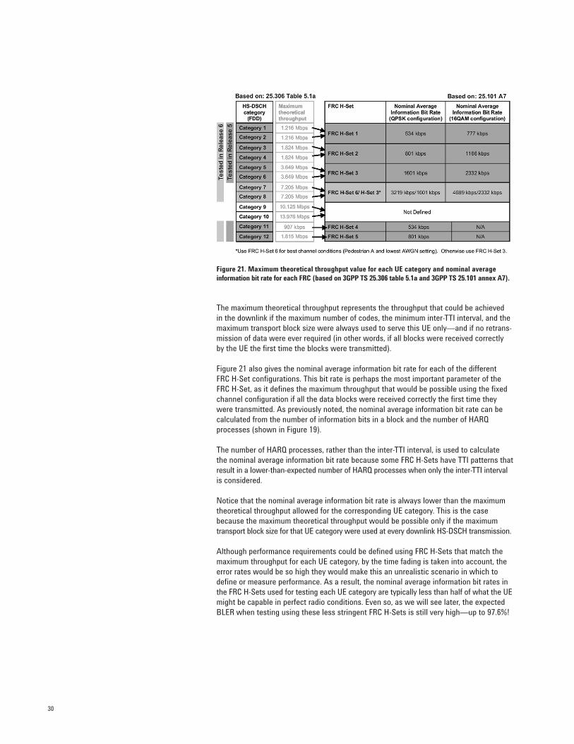
The UE parameters listed in Figure 20 define the maximum theoretical throughput thateach UE category allows. This maximum theoretical throughput is given in Figure 21 foreach UE category. It is calculated by dividing the maximum HS-DSCH transport block sizefor a category by the TTI length (2 ms) and dividing again the result by the minimum inter-TTI interval. The higher the minimum inter-TTI interval, the lower the number of parallelHARQ processes allowed, which results in a lower throughput.
30
Figure 21. Maximum theoretical throughput value for each UE category and nominal average information bit rate for each FRC (based on 3GPP TS 25.306 table 5.1a and 3GPP TS 25.101 annex A7).
The maximum theoretical throughput represents the throughput that could be achieved in the downlink if the maximum number of codes, the minimum inter-TTI interval, and themaximum transport block size were always used to serve this UE only—and if no retrans-mission of data were ever required (in other words, if all blocks were received correctly by the UE the first time the blocks were transmitted).
Figure 21 also gives the nominal average information bit rate for each of the different FRC H-Set configurations. This bit rate is perhaps the most important parameter of theFRC H-Set, as it defines the maximum throughput that would be possible using the fixedchannel configuration if all the data blocks were received correctly the first time theywere transmitted. As previously noted, the nominal average information bit rate can becalculated from the number of information bits in a block and the number of HARQprocesses (shown in Figure 19).
The number of HARQ processes, rather than the inter-TTI interval, is used to calculate the nominal average information bit rate because some FRC H-Sets have TTI patterns thatresult in a lower-than-expected number of HARQ processes when only the inter-TTI intervalis considered.
Notice that the nominal average information bit rate is always lower than the maximumtheoretical throughput allowed for the corresponding UE category. This is the casebecause the maximum theoretical throughput would be possible only if the maximumtransport block size for that UE category were used at every downlink HS-DSCH transmission.
Although performance requirements could be defined using FRC H-Sets that match themaximum throughput for each UE category, by the time fading is taken into account, theerror rates would be so high they would make this an unrealistic scenario in which todefine or measure performance. As a result, the nominal average information bit rates inthe FRC H-Sets used for testing each UE category are typically less than half of what the UEmight be capable in perfect radio conditions. Even so, as we will see later, the expectedBLER when testing using these less stringent FRC H-Sets is still very high—up to 97.6%!
31
Downlink configuration of HARQ transmissions
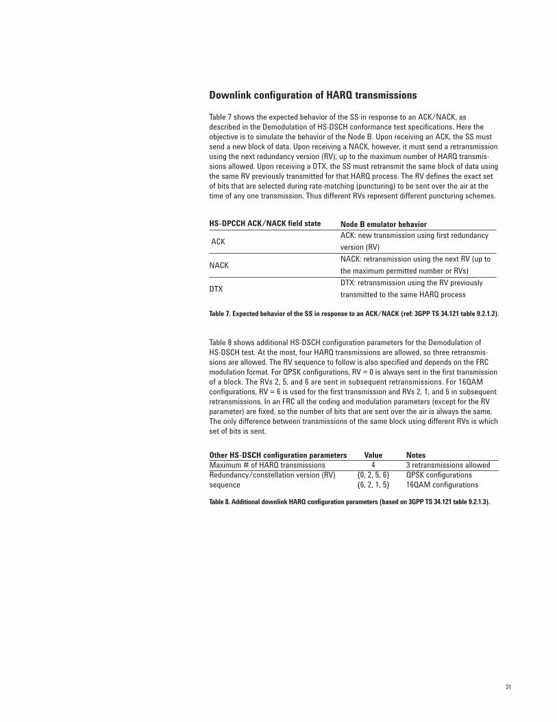
Table 7 shows the expected behavior of the SS in response to an ACK/NACK, asdescribed in the Demodulation of HS-DSCH conformance test specifications. Here theobjective is to simulate the behavior of the Node B. Upon receiving an ACK, the SS mustsend a new block of data. Upon receiving a NACK, however, it must send a retransmissionusing the next redundancy version (RV), up to the maximum number of HARQ transmis-sions allowed. Upon receiving a DTX, the SS must retransmit the same block of data usingthe same RV previously transmitted for that HARQ process. The RV defines the exact setof bits that are selected during rate-matching (puncturing) to be sent over the air at thetime of any one transmission. Thus different RVs represent different puncturing schemes.
Table 7. Expected behavior of the SS in response to an ACK/NACK (ref: 3GPP TS 34.121 table 9.2.1.2).
Table 8 shows additional HS-DSCH configuration parameters for the Demodulation of HS-DSCH test. At the most, four HARQ transmissions are allowed, so three retransmis-sions are allowed. The RV sequence to follow is also specified and depends on the FRCmodulation format. For QPSK configurations, RV = 0 is always sent in the first transmissionof a block. The RVs 2, 5, and 6 are sent in subsequent retransmissions. For 16QAM configurations, RV = 6 is used for the first transmission and RVs 2, 1, and 5 in subsequentretransmissions. In an FRC all the coding and modulation parameters (except for the RVparameter) are fixed, so the number of bits that are sent over the air is always the same.The only difference between transmissions of the same block using different RVs is whichset of bits is sent.
Table 8. Additional downlink HARQ configuration parameters (based on 3GPP TS 34.121 table 9.2.1.3).
HS-DPCCH ACK/NACK field state Node B emulator behavior
ACKACK: new transmission using first redundancy
version (RV)
NACKNACK: retransmission using the next RV (up to
the maximum permitted number or RVs)
DTXDTX: retransmission using the RV previously
transmitted to the same HARQ process
Other HS-DSCH configuration parameters Value NotesMaximum # of HARQ transmissions 4 3 retransmissions allowed Redundancy/constellation version (RV) {0, 2, 5, 6} QPSK configurationssequence {6, 2, 1, 5} 16QAM configurations
32
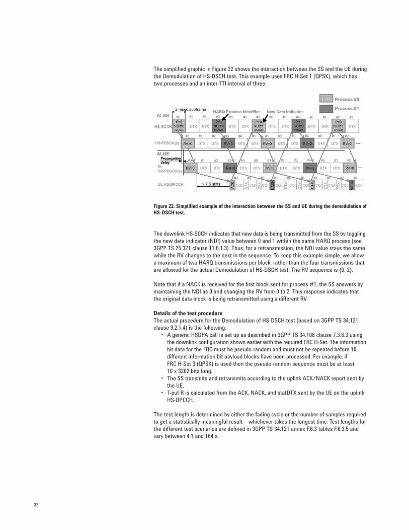
The simplified graphic in Figure 22 shows the interaction between the SS and the UE duringthe Demodulation of HS-DSCH test. This example uses FRC H-Set 1 (QPSK), which hastwo processes and an inter-TTI interval of three.
Figure 22. Simplified example of the interaction between the SS and UE during the demodulation ofHS-DSCH test.
The downlink HS-SCCH indicates that new data is being transmitted from the SS by togglingthe new data indicator (NDI) value between 0 and 1 within the same HARQ process (see3GPP TS 25.321 clause 11.6.1.3). Thus, for a retransmission, the NDI value stays the samewhile the RV changes to the next in the sequence. To keep this example simple, we allowa maximum of two HARQ transmissions per block, rather than the four transmissions thatare allowed for the actual Demodulation of HS-DSCH test. The RV sequence is {0, 2}.
Note that if a NACK is received for the first block sent for process #1, the SS answers bymaintaining the NDI as 0 and changing the RV from 0 to 2. This response indicates thatthe original data block is being retransmitted using a different RV.
Details of the test procedureThe actual procedure for the Demodulation of HS-DSCH test (based on 3GPP TS 34.121clause 9.2.1.4) is the following:
• A generic HSDPA call is set up as described in 3GPP TS 34.108 clause 7.3.6.3 using the downlink configuration shown earlier with the required FRC H-Set. The informationbit data for the FRC must be pseudo-random and must not be repeated before 10 different information bit payload blocks have been processed. For example, if FRC H-Set 3 (QPSK) is used then the pseudo-random sequence must be at least 10 x 3202 bits long.
• The SS transmits and retransmits according to the uplink ACK/NACK report sent by the UE.
• T-put R is calculated from the ACK, NACK, and statDTX sent by the UE on the uplink HS-DPCCH.
The test length is determined by either the fading cycle or the number of samples requiredto get a statistically meaningful result—whichever takes the longest time. Test lengths forthe different test scenarios are defined in 3GPP TS 34.121 annex F.6.3 tables F.6.3.5 andvary between 4.1 and 164 s.
33
Minimum requirement T-put R for Îor/Ioc = 0 dB
FRC H-Set 1 FRC H-Set 2 FRC H-Set 3
(QPSK) (QPSK) (QPSK)Propagation Ec/Ior
2 processes 3 processes 6 processesconditions (dB)
Nom. Avg. Inf. Bit Nom. Avg. Inf. Bit Nom. Avg. Inf. Bit
Rate = 534 kbps Rate = 801 kbps Rate = 1601 kbps
PA3 –6 65 kbps x 1.5 x 3
PB3–6 23 kbps x 1.5 x 3
–3 138 kbps x 1.5 x 3
VA30–6 22 kbps x 1.5 x 3
–3 142 kbps x 1.5 x 3
VA120–6 13 kbps x 1.5 x 3
–3 140 kbps x 1.5 x 3
BLER (%)
87.8
95.7
74.2
95.9
73.4
97.6
73.8
Typical macro cellgeometry factor Minimum
requirements are no
indication of real-life
performance with
AMC
Minimum requirements
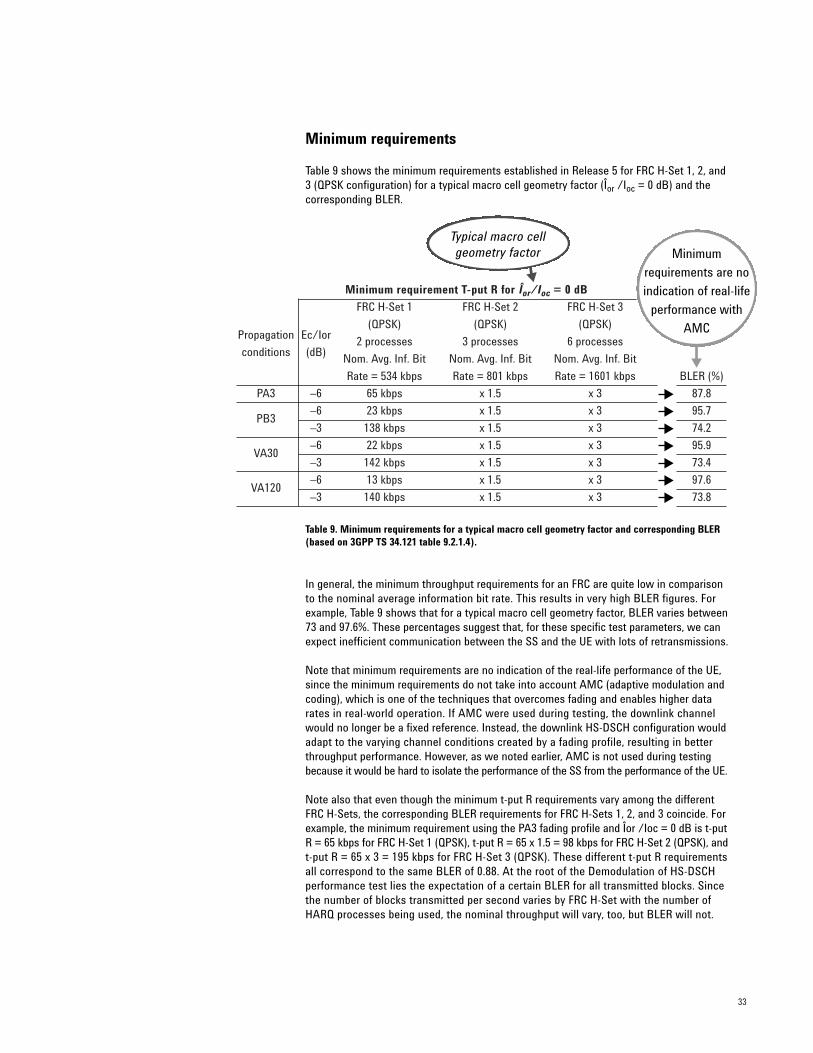
Table 9 shows the minimum requirements established in Release 5 for FRC H-Set 1, 2, and3 (QPSK configuration) for a typical macro cell geometry factor (Îor /Ioc = 0 dB) and thecorresponding BLER.
Table 9. Minimum requirements for a typical macro cell geometry factor and corresponding BLER(based on 3GPP TS 34.121 table 9.2.1.4).
In general, the minimum throughput requirements for an FRC are quite low in comparisonto the nominal average information bit rate. This results in very high BLER figures. Forexample, Table 9 shows that for a typical macro cell geometry factor, BLER varies between73 and 97.6%. These percentages suggest that, for these specific test parameters, we canexpect inefficient communication between the SS and the UE with lots of retransmissions.
Note that minimum requirements are no indication of the real-life performance of the UE,since the minimum requirements do not take into account AMC (adaptive modulation andcoding), which is one of the techniques that overcomes fading and enables higher datarates in real-world operation. If AMC were used during testing, the downlink channelwould no longer be a fixed reference. Instead, the downlink HS-DSCH configuration wouldadapt to the varying channel conditions created by a fading profile, resulting in betterthroughput performance. However, as we noted earlier, AMC is not used during testingbecause it would be hard to isolate the performance of the SS from the performance of the UE.
Note also that even though the minimum t-put R requirements vary among the differentFRC H-Sets, the corresponding BLER requirements for FRC H-Sets 1, 2, and 3 coincide. Forexample, the minimum requirement using the PA3 fading profile and Îor /Ioc = 0 dB is t-putR = 65 kbps for FRC H-Set 1 (QPSK), t-put R = 65 x 1.5 = 98 kbps for FRC H-Set 2 (QPSK), andt-put R = 65 x 3 = 195 kbps for FRC H-Set 3 (QPSK). These different t-put R requirementsall correspond to the same BLER of 0.88. At the root of the Demodulation of HS-DSCH performance test lies the expectation of a certain BLER for all transmitted blocks. Sincethe number of blocks transmitted per second varies by FRC H-Set with the number ofHARQ processes being used, the nominal throughput will vary, too, but BLER will not.
34
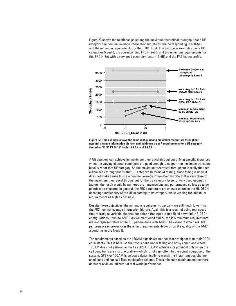
Figure 23 shows the relationships among the maximum theoretical throughput for a UEcategory, the nominal average information bit rate for the corresponding FRC H-Set, and the minimum requirements for that FRC H-Set. This particular example covers UE categories 5 and 6, the corresponding FRC H-Set 3, and the minimum requirements forthis FRC H-Set with a very good geometry factor (10 dB) and the PA3 fading profile.
Figure 23. This example shows the relationship among maximum theoretical throughput, nominal average information bit rate, and minimum t-put R requirements for a UE category(based on 3GPP TS 34.121 tables 9.2.1.4 and 9.2.1.6).
A UE category can achieve its maximum theoretical throughput only at specific instanceswhen the varying channel conditions are good enough to support the maximum transportblock size for that UE category. So the maximum theoretical throughput is really the theo-retical peak throughput for that UE category. In terms of testing, since fading is used, itdoes not make sense to use a nominal average information bit rate that is very close tothe maximum theoretical throughput for the UE category. Even for very good geometryfactors, the result would be numerous retransmissions and performance so low as to bepointless to measure. In general, the FRC parameters are chosen to stress the HS-DSCHdecoding functionality of the UE according to its category, while keeping the minimumrequirements as high as possible.
Despite these objectives, the minimum requirements typically are still much lower thanthe FRC nominal average information bit rate. Again this is a result of using test casesthat reproduce variable channel conditions (fading) but use fixed downlink HS-DSCH configurations (thus no AMC). As we mentioned earlier, the low minimum requirementsare not representative of real UE performance with AMC. The extent to which real lifeperformance improves over these test requirements depends on the quality of the AMCalgorithms in the Node B.
The requirements based on the 16QAM signals are not necessarily higher than their QPSKequivalents. This is because the test is done under fading and noisy conditions where16QAM does not perform as well as QPSK. 16QAM achieves its potential only when thecell conditions are most favorable—which is not very often. In the actual operation of thesystem, QPSK or 16QAM is selected dynamically to match the instantaneous channelconditions and not as a fixed modulation scheme. These minimum requirements thereforedo not provide an indicator of real-world performance.
35
Reporting of CQI (34.121 9.3)
The next category of HSDPA performance requirements tests is the Reporting of CQI(34.121 9.3). Two different tests are included under this heading: Reporting of CQI under AWGN Propagation Conditions (34.121 9.3.1) and Reporting of CQI under FadingPropagation Conditions (34.121 9.3.2). Although these tests have similar purposes, some differences exist in their procedures.
Reporting of CQI under AWGN Propagation Conditions (34.121 9.3.1)
This test evaluates the accuracy of the CQI reporting under stable propagation conditions.
The test procedure has two parts, each of which uses a different metric to evaluate a specific aspect of the reporting accuracy.
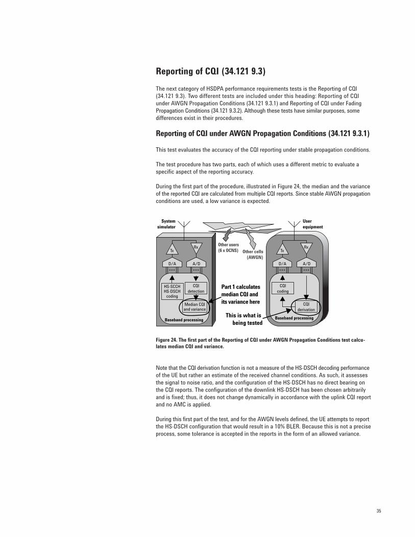
During the first part of the procedure, illustrated in Figure 24, the median and the varianceof the reported CQI are calculated from multiple CQI reports. Since stable AWGN propagationconditions are used, a low variance is expected.
Figure 24. The first part of the Reporting of CQI under AWGN Propagation Conditions test calcu-lates median CQI and variance.
Note that the CQI derivation function is not a measure of the HS-DSCH decoding performanceof the UE but rather an estimate of the received channel conditions. As such, it assessesthe signal to noise ratio, and the configuration of the HS-DSCH has no direct bearing onthe CQI reports. The configuration of the downlink HS-DSCH has been chosen arbitrarilyand is fixed; thus, it does not change dynamically in accordance with the uplink CQI reportand no AMC is applied.
During this first part of the test, and for the AWGN levels defined, the UE attempts to reportthe HS-DSCH configuration that would result in a 10% BLER. Because this is not a preciseprocess, some tolerance is accepted in the reports in the form of an allowed variance.
CQIcoding
CQIdetection
CQIderivation
HS-SCCHHS-DSCH
coding
Median CQIand variance
Tx
D/A A/D
Rx
Baseband processing
Userequipment
Tx
D/A A/D
Rx
Baseband processing
Systemsimulator
Other users(6 x OCNS)
Part 1 calculatesmedian CQI and its variance here
This is what is being tested
Other cells(AWGN)
36
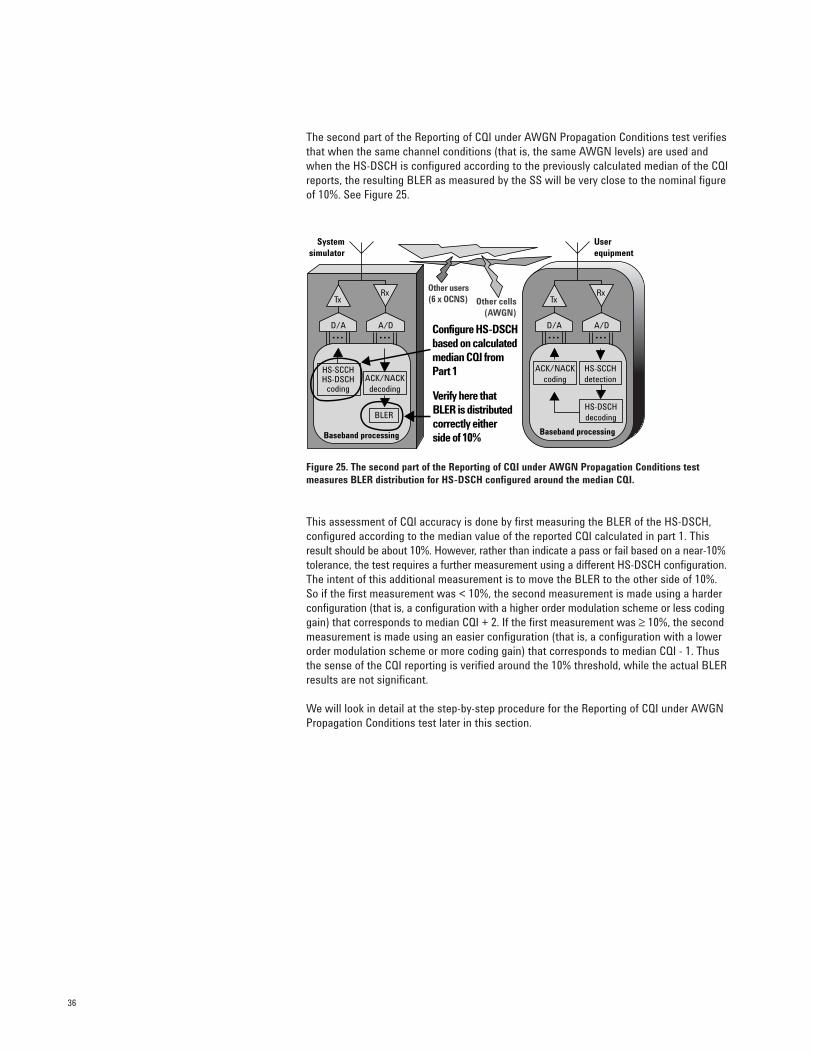
The second part of the Reporting of CQI under AWGN Propagation Conditions test verifiesthat when the same channel conditions (that is, the same AWGN levels) are used andwhen the HS-DSCH is configured according to the previously calculated median of the CQIreports, the resulting BLER as measured by the SS will be very close to the nominal figureof 10%. See Figure 25.
Figure 25. The second part of the Reporting of CQI under AWGN Propagation Conditions testmeasures BLER distribution for HS-DSCH configured around the median CQI.
This assessment of CQI accuracy is done by first measuring the BLER of the HS-DSCH,configured according to the median value of the reported CQI calculated in part 1. Thisresult should be about 10%. However, rather than indicate a pass or fail based on a near-10%tolerance, the test requires a further measurement using a different HS-DSCH configuration.The intent of this additional measurement is to move the BLER to the other side of 10%.So if the first measurement was < 10%, the second measurement is made using a harderconfiguration (that is, a configuration with a higher order modulation scheme or less codinggain) that corresponds to median CQI + 2. If the first measurement was ≥ 10%, the secondmeasurement is made using an easier configuration (that is, a configuration with a lowerorder modulation scheme or more coding gain) that corresponds to median CQI - 1. Thusthe sense of the CQI reporting is verified around the 10% threshold, while the actual BLERresults are not significant.
We will look in detail at the step-by-step procedure for the Reporting of CQI under AWGNPropagation Conditions test later in this section.
ACK/NACKcoding
HS-DSCHdecoding
HS-SCCHHS-DSCH
coding
BLER
ACK/NACKdecoding
HS-SCCHdetection
Tx
D/A A/D
Rx
Baseband processing
Userequipment
Tx
D/A A/D
Rx
Baseband processing
Systemsimulator
Other users(6 x OCNS)
Verify here that BLER is distributed correctly either side of 10%
Other cells(AWGN)
Configure HS-DSCHbased on calculatedmedian CQI from Part 1
37
Test-specific parameters
Table 10 shows the downlink channel configuration test parameters that are specific tothe Reporting of CQI under AWGN Propagation Conditions test. This table complementsthe general downlink test configuration table previously discussed. For simplicity, Table 10includes only those parameters that correspond to the single link performance specifiedin Release 5. The numerical values used in the table represent the minimum requirementsfrom 3GPP TS 25.101, not the relaxed test requirements from 3GPP TS 34.121 that takeinto account test system uncertainty.
Table 10. Test-specific downlink parameters for Reporting of CQI under AWGN PropagationConditions single link performance in Release 5 (based on 3GPP TS 34.121 table 9.3.1.1).
The most important parameter for this test is the signal-to-noise ratio or cell geometryfactor (Îor /Ioc). Since no fading is used in this test, the UE reports on stable channelconditions that are represented by the different geometry factors: typical (0 dB), good (5 dB),or very good (10 dB).
The HS-DSCH is configured for this test according to several CQI values. In the first partof the test, the HS-DSCH is arbitrarily configured for CQI = 16, as this value does notaffect the test results (that is, the reported CQI median and variance). For the second partof the test, the HS-DSCH is configured according to the previously calculated median CQIand either the median CQI + 2 or median CQI – 1.
The six-subframe HS-SCCH-1 signaling pattern for this test is defined as “…XOOXOO…,”wherein “X” indicates a TTI in which the HS-SCCH-1 uses the identity of the UE undertest, and “O” indicates a TTI in which the HS-SCCH-1 uses a different UE identity.Therefore, blocks intended for the UE under test appear every third TTI only, which all UEsupport.
Table 11 shows additional test configuration parameters that are important for this test.Note that the uplink CQI feedback cycle is 2 ms and the CQI repetition factor is 1, so anew CQI report is sent by the UE every subframe.
Table 11. Additional test parameters for Reporting of CQI under AWGN Propagation Conditions(based on 3GPP TS 34.121 table 9.3.1.1).
Signal Level vs. Ioc @ –60 dBm Notes
Îor 0, 5, or 10 dB Typical, good, or very good geometry factor
Channel Level vs. Ior Notes
DPCH –10 dB 12.2 k RMC
HS-SCCH-1 –10 dB TTI signalling pattern: “…XOOXOO…”
HS-SCCH-2, 3, 4 are off (DTX)
HS-DSCH (HS-PDSCHs) –3 dB total Configuration based on CQI = 16, median CQI,
median CQI + 2, or median CQI – 1
Other configuration parameters Value NotesCQI feedback cycle 2 ms CQI transmitted every 2 ms CQI repetition factor 1 CQI report is never repeated
38
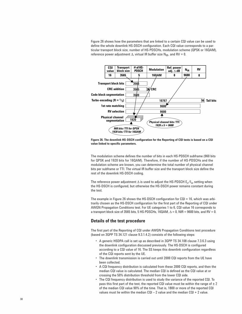
Figure 26 shows how the parameters that are linked to a certain CQI value can be used todefine the whole downlink HS-DSCH configuration. Each CQI value corresponds to a par-ticular transport block size, number of HS-PDSCHs, modulation scheme (QPSK or 16QAM),reference power adjustment ∆, virtual IR buffer size NIR, and RV = 0.
Figure 26. The downlink HS-DSCH configuration for the Reporting of CQI tests is based on a CQIvalue linked to specific parameters.
The modulation scheme defines the number of bits in each HS-PDSCH subframe (960 bitsfor QPSK and 1920 bits for 16QAM). Therefore, if the number of HS-PDSCHs and the modulation scheme are known, you can determine the total number of physical channelbits per subframe or TTI. The virtual IR buffer size and the transport block size define therest of the downlink HS-DSCH coding.
The reference power adjustment ∆ is used to adjust the HS-PDSCH Ec/Ior setting whenthe HS-DSCH is configured, but otherwise the HS-DSCH power remains constant duringthe test.
The example in Figure 26 shows the HS-DSCH configuration for CQI = 16, which was arbi-trarily chosen as the HS-DSCH configuration for the first part of the Reporting of CQI underAWGN Propagation Conditions test. For UE categories 1 to 6, CQI value 16 corresponds toa transport block size of 3565 bits, 5 HS-PDSCHs, 16QAM, ∆ = 0, NIR = 9600 bits, and RV = 0.
Details of the test procedure
The first part of the Reporting of CQI under AWGN Propagation Conditions test procedure(based on 3GPP TS 34.121 clause 9.3.1.4.2) consists of the following steps:
• A generic HSDPA call is set up as described in 3GPP TS 34.108 clause 7.3.6.3 using the downlink configuration discussed previously. The HS-DSCH is configured according to a CQI value of 16. The SS keeps this downlink configuration regardless of the CQI reports sent by the UE.
• The downlink transmission is carried out until 2000 CQI reports from the UE have been collected.
• A CQI frequency distribution is calculated from these 2000 CQI reports, and then the median CQI value is calculated. The median CQI is defined as the CQI value at or crossing the 50% distribution threshold from the lower CQI side.
• The CQI frequency distribution is used to study the variance of the reported CQI. To pass this first part of the test, the reported CQI value must be within the range of ± 2of the median CQI value 90% of the time. That is, 1800 or more of the reported CQI values must lie within the median CQI – 2 value and the median CQI + 2 value.
CQIvalue
# of HS-PDSCH
Transportblock size Modulation
Ref. poweradj. ∆ dB RVNIR
16 3565 5 16QAM 0 9600 0
Transport block bits
CRC addition
Code block segmentation
Turbo-encoding (R = 1/3)
1st rate matching
RV selection
Physical channel segmentation 1920
3565
3565
3589
10767
9600
9600
24 CRC
14 Tail bits
Physical channel bits/TTI:1920 x 5 = 9600
960 bits/TTI for QPSK1920 bits/TTI for 16QAM
Median CQI – 2 = 11 Median CQI + 2 = 15
CQI value
CQI frequency distribution
> 1800 reports betweenCQI = 11 and CQI = 15
PASSFollow part 2
800700600500400300200100
01 3 5 7 9 11 13 15 17 19 21 23 25 27 29
39
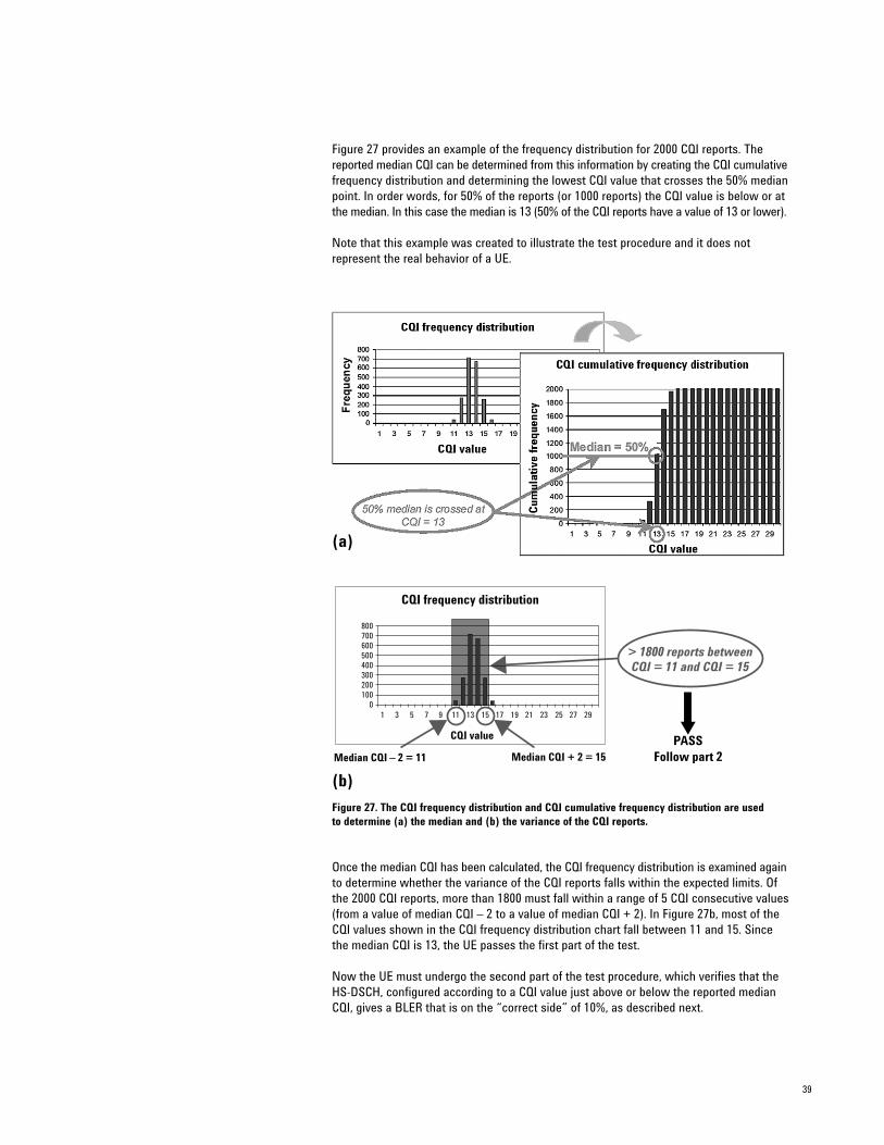
Figure 27 provides an example of the frequency distribution for 2000 CQI reports. Thereported median CQI can be determined from this information by creating the CQI cumulativefrequency distribution and determining the lowest CQI value that crosses the 50% medianpoint. In order words, for 50% of the reports (or 1000 reports) the CQI value is below or atthe median. In this case the median is 13 (50% of the CQI reports have a value of 13 or lower).
Note that this example was created to illustrate the test procedure and it does not represent the real behavior of a UE.
(a)
(b)
Figure 27. The CQI frequency distribution and CQI cumulative frequency distribution are used to determine (a) the median and (b) the variance of the CQI reports.
Once the median CQI has been calculated, the CQI frequency distribution is examined againto determine whether the variance of the CQI reports falls within the expected limits. Ofthe 2000 CQI reports, more than 1800 must fall within a range of 5 CQI consecutive values(from a value of median CQI – 2 to a value of median CQI + 2). In Figure 27b, most of theCQI values shown in the CQI frequency distribution chart fall between 11 and 15. Sincethe median CQI is 13, the UE passes the first part of the test.
Now the UE must undergo the second part of the test procedure, which verifies that theHS-DSCH, configured according to a CQI value just above or below the reported medianCQI, gives a BLER that is on the “correct side” of 10%, as described next.
40
The second part of the test (based on 3GPP TS 34.121 clause 9.3.1.4.2) proceeds as follows:
• The HS-DSCH is configured according to the median CQI value calculated during the first part of the test. The SS keeps this downlink configuration regardless of the CQI reports sent by the UE.
• BLER is calculated based on the ACK/NACK reports for 1000 blocks. • If BLER is less than 0.1, the HS-DSCH is configured according to a value of median
CQI + 2 and BLER is calculated again for another 1000 blocks. The purpose of this step is to verify that when a more difficult HS-DSCH configuration is used, the BLER will be at or above the 10% reference used for the UE’s calculation of the CQI report.
• If BLER is greater than 0.1, the HS-DSCH is configured according to a value of medianCQI + 1 and BLER is calculated again for another 1000 blocks. The purpose of this step is to verify that when an easier HS-DSCH configuration is used, the BLER will be below the 10% reference used for the UE’s calculation of the CQI report.
To summarize briefly the complete test procedure for CQI reporting under static (AWGN)conditions:
• Measure the median CQI using a specific AWGN level.• Verify that the CQI variance is within limits.• Measure the BLER using an HS-DSCH configured for the median CQI.• Verify one of the following:• If the measured BLER at median CQI is < 10%, verify that using a harder HS-DSCH
configuration produces BLER ≥ 10%.• If the measured BLER at median CQI is ≥ 10%, verify that using an easier HS-DSCH
configuration produces BLER < 10%.
Remember that the absolute CQI reports are of no consequence in this procedure. We areconcerned only with the CQI variance and the measured BLER using HS-DSCH configuredat or near the median CQI.
41
CQIcoding
CQIderivation
ACK/NACK
decoding
ACK/NACKcoding
CQIdecoding
HS-SCCHdetection
HS-DSCHdecoding
HS-SCCHHS-DSCH
coding
Event R1Event R2
BLER
Fading channel
Tx
D/A A/D
Rx
Baseband processing
Userequipment
Tx
D/A A/D
Rx
Baseband processing
Systemsimulator
This is what isbeing tested
Other users(6 x OCNS) Other cells
(AWGN)
Identify CQI associated with each received block
Measure BLER for blocks received when CQI values are R1 or R2
Configure HS-DSCH based on calculated median CQI
Reporting of CQI Under Fading Propagation Conditions(34.121 9.3.2)
This test evaluates the accuracy of the CQI reporting under multi-path propagation conditions. It requires the UE to track the real time variation in channel conditions.Because the propagation conditions are not stable, the reported CQI values will likely varyconsiderably. Therefore, the variance of the CQI reports is not used as a metric, as it wasin the first part of the previous (AWGN propagation conditions) test.
For the Reporting of CQI under Fading Propagation Conditions test, the median CQI is calculated from multiple CQI reports and is used to configure the HS-DSCH. As in the previous test, the configuration of the downlink HS-DSCH is fixed and so does not changedynamically in accordance with the uplink CQI report. Once again, no AMC is applied.
The fading propagation conditions test examines two different events representing twodifferent instantaneous channel conditions. Event R1 represents the instantaneous channelconditions that are reported by the UE with a value equal to the calculated median CQI.
Event R2 represents the instantaneous channel conditions that are reported by the UEwith a value equal to the median CQI + 3. Therefore, event R2 corresponds to better perceived channel conditions than does event R1.
To verify that the UE is correctly reporting the CQI during non-constant channel conditions,the BLER is calculated independently for event R1 periods (when CQI is reported as themedian CQI) and for event R2 periods (when CQI is reported as the median CQI + 3).
As noted previously, the BLER for HS-DSCH blocks received during event R2 channel conditions should be lower than the BLER for blocks received during event R1. This is truebecause event R2 represents better instantaneous channel conditions, thus resulting in alower rate of error. Remember that the HS-DSCH configuration does not change during the test. Therefore, the variations of BLER follow exclusively the variations of the instantaneous channel conditions.
Figure 28 illustrates the general test process. The exact test procedure will be described later.
Figure 28. Reporting of CQI under Fading Propagation Conditions tests the accuracy of CQI reportingunder multi-path propagation conditions.
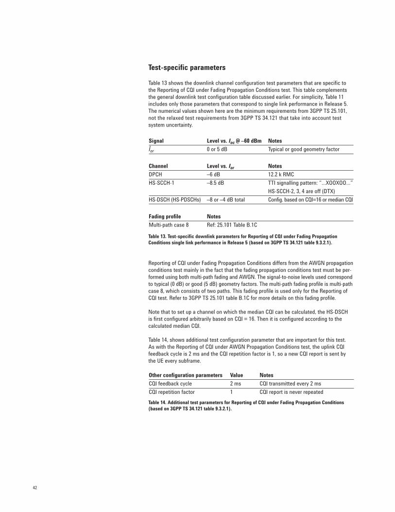
42
Test-specific parameters
Table 13 shows the downlink channel configuration test parameters that are specific tothe Reporting of CQI under Fading Propagation Conditions test. This table complementsthe general downlink test configuration table discussed earlier. For simplicity, Table 11includes only those parameters that correspond to single link performance in Release 5.The numerical values shown here are the minimum requirements from 3GPP TS 25.101,not the relaxed test requirements from 3GPP TS 34.121 that take into account test system uncertainty.
Table 13. Test-specific downlink parameters for Reporting of CQI under Fading PropagationConditions single link performance in Release 5 (based on 3GPP TS 34.121 table 9.3.2.1).
Reporting of CQI under Fading Propagation Conditions differs from the AWGN propagationconditions test mainly in the fact that the fading propagation conditions test must be per-formed using both multi-path fading and AWGN. The signal-to-noise levels used correspondto typical (0 dB) or good (5 dB) geometry factors. The multi-path fading profile is multi-pathcase 8, which consists of two paths. This fading profile is used only for the Reporting ofCQI test. Refer to 3GPP TS 25.101 table B.1C for more details on this fading profile.
Note that to set up a channel on which the median CQI can be calculated, the HS-DSCH is first configured arbitrarily based on CQI = 16. Then it is configured according to the calculated median CQI.
Table 14, shows additional test configuration parameter that are important for this test. As with the Reporting of CQI under AWGN Propagation Conditions test, the uplink CQIfeedback cycle is 2 ms and the CQI repetition factor is 1, so a new CQI report is sent bythe UE every subframe.
Table 14. Additional test parameters for Reporting of CQI under Fading Propagation Conditions(based on 3GPP TS 34.121 table 9.3.2.1).
Signal Level vs. Ioc @ –60 dBm Notes
Îor 0 or 5 dB Typical or good geometry factor
Channel Level vs. Ior Notes
DPCH –6 dB 12.2 k RMC
HS-SCCH-1 –8.5 dB TTI signalling pattern: “…XOOXOO…”
HS-SCCH-2, 3, 4 are off (DTX)
HS-DSCH (HS-PDSCHs) –8 or –4 dB total Config. based on CQI=16 or median CQI
Fading profile Notes
Multi-path case 8 Ref: 25.101 Table B.1C
Other configuration parameters Value Notes
CQI feedback cycle 2 ms CQI transmitted every 2 ms
CQI repetition factor 1 CQI report is never repeated

43
Details of the test procedure
The procedure for the Reporting of CQI under Fading Propagation Conditions test, basedon 3GPP TS 34.121 clause 9.3.2.4.2, consists of the following:
• A generic HSDPA call is set up as described in 3GPP TS 34.108 clause 7.3.6.3 using the downlink configuration shown earlier. The HS-DSCH is configured according to a CQI value of 16. The SS keeps this downlink configuration regardless of the CQI reports sent by the UE.
• The downlink transmission is continued until 2000 CQI reports are collected from the UE. A frequency distribution is calculated for the reported CQI values and then the median CQI is calculated.
• The downlink HS-DSCH is configured again, this time according to the calculated median CQI. The SS keeps this downlink configuration regardless of the CQI reports sent by the UE.
BLER is calculated for two different events:
• For 1000 blocks transmitted during event R1 instantaneous propagation conditions (when the reported CQI value is equal to the median CQI value calculated earlier). The BLER for event R1 must be lower than 60%.
• For 1000 blocks transmitted during event R2 instantaneous propagation conditions (when the reported CQI is equal to the median CQI + 3). The BLER for event R2 must be lower than 15%.
Figure 29 illustrates the procedure to calculate BLER for events R1 and R2. In this exam-ple, the median CQI has already been calculated and it is 17.
Figure 29. BLER is calculated for events R1 and R2.
The key to understanding the Reporting of CQI under Fading Propagation Conditions testlies in understanding both the definition of CQI found in the specifications (see 3GPP TS25.214 clause 6A.2) and the means of correctly associating the physical events with thereports from the UE.
44
According to the specifications, the CQI is derived for a three-slot reference period endingone slot before the start of the first slot in which the reported CQI value is transmitted. For the purposes of the BLER calculation, the associated HS-PDSCH subframes are thesubframes that start their transmission during these reference periods.
Event R1 occurs when the CQI report associated with a transmitted HS-PDSCH subframehas the same value as the previously calculated median CQI (17 in this case). The ACK/NACKreport must be collected for 1000 of these events and the BLER must be calculated. InFigure 28, for example, event R1 occurs only once. The ACK/NACK report for the associatedHS-DSCH block is a NACK, so the preliminary BLER count for event R1 in this example isBLER = 1/1.
Event R2 occurs when the CQI report associated with a transmitted HS-PDSCH subframehas the same value as the previously calculated median CQI + 3 (20 in this case). TheACK/NACK report must be collected for 1000 of these events and the BLER must be calculated. In Figure 28, event R2 occurs also only once. The ACK/NACK report for theassociated HS-DSCH block is an ACK, so the preliminary BLER count for event R2 in thisexample is BLER = 0/1.
The minimum requirements for this test (BLER < 60% for R1 and BLER < 15% for R2) arebased on the expectation discussed earlier that the BLER for event R2 will be much lowerthan the BLER for event R1. The blocks associated with event R2 are transmitted duringbetter link conditions, according to the CQI report—that is, the reported CQI value forevent R2 is higher than the reported CQI value for event R1.
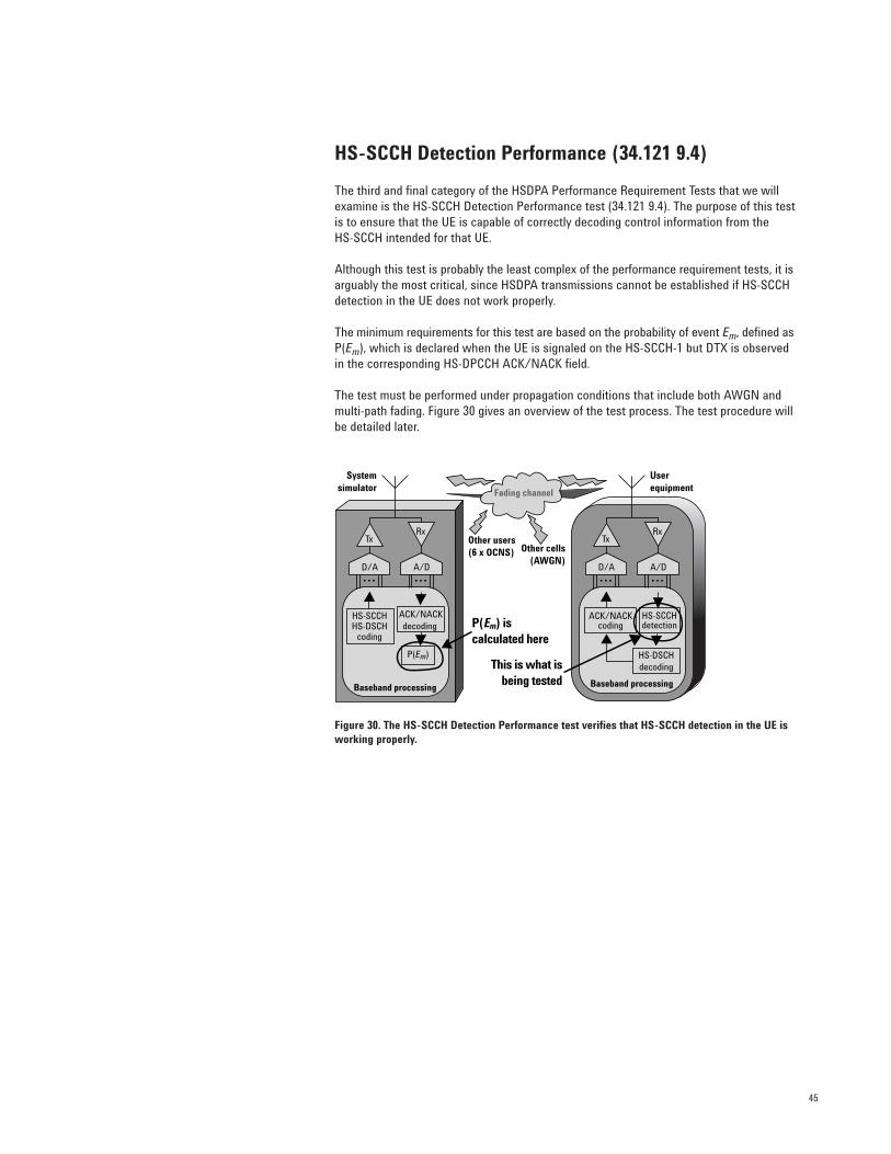
45
HS-SCCH Detection Performance (34.121 9.4)
The third and final category of the HSDPA Performance Requirement Tests that we willexamine is the HS-SCCH Detection Performance test (34.121 9.4). The purpose of this testis to ensure that the UE is capable of correctly decoding control information from the HS-SCCH intended for that UE.
Although this test is probably the least complex of the performance requirement tests, it isarguably the most critical, since HSDPA transmissions cannot be established if HS-SCCHdetection in the UE does not work properly.
The minimum requirements for this test are based on the probability of event Em, defined asP(Em), which is declared when the UE is signaled on the HS-SCCH-1 but DTX is observedin the corresponding HS-DPCCH ACK/NACK field.
The test must be performed under propagation conditions that include both AWGN andmulti-path fading. Figure 30 gives an overview of the test process. The test procedure willbe detailed later.
Figure 30. The HS-SCCH Detection Performance test verifies that HS-SCCH detection in the UE isworking properly.
ACK/NACKdecoding
HS-SCCHHS-DSCH
coding
P(Em)
Tx
D/A A/D
Rx
Baseband processing
Userequipment
Tx
D/A A/D
Rx
Baseband processing
Systemsimulator
P(Em) is calculated here
This is what isbeing tested
ACK/NACKcoding
HS-SCCHdetection
HS-DSCHdecoding
Fading channel
Other users(6 x OCNS) Other cells
(AWGN)
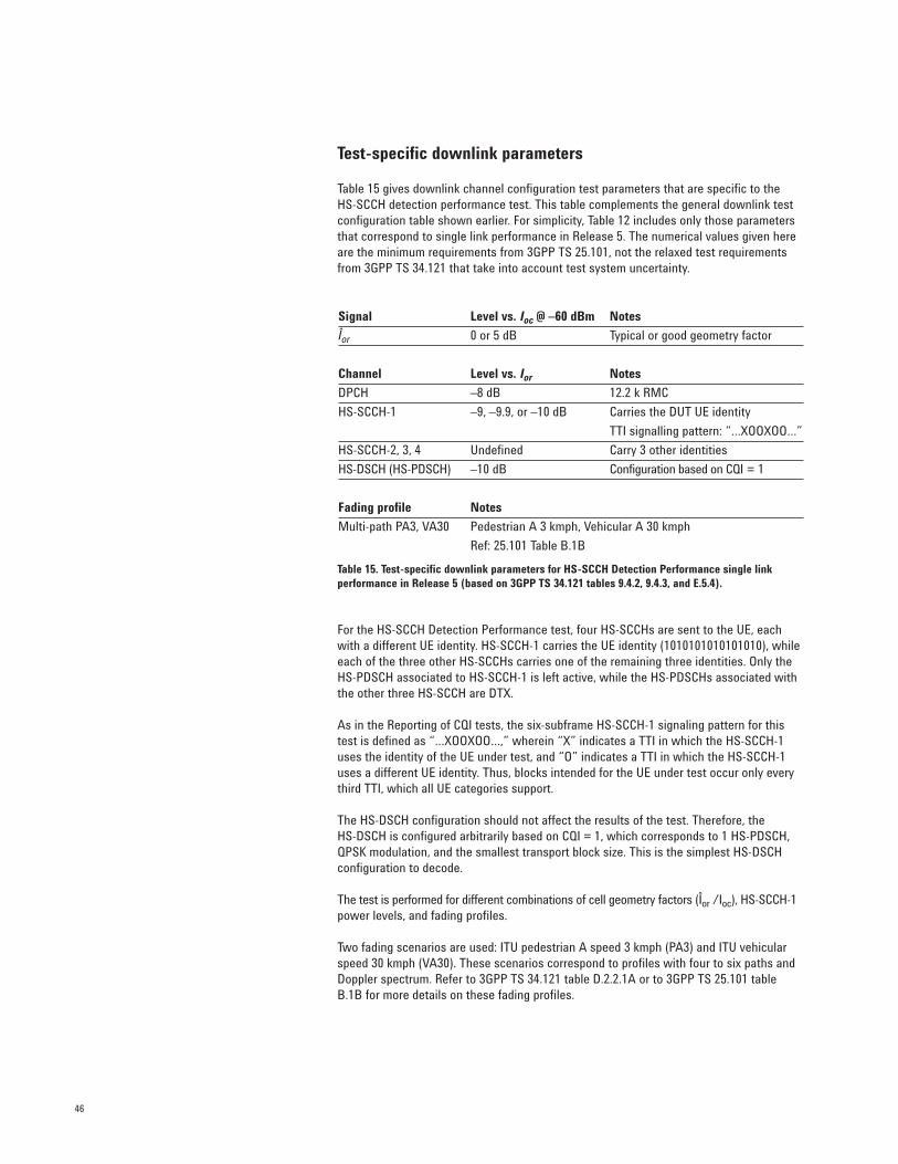
46
Test-specific downlink parameters
Table 15 gives downlink channel configuration test parameters that are specific to the HS-SCCH detection performance test. This table complements the general downlink testconfiguration table shown earlier. For simplicity, Table 12 includes only those parametersthat correspond to single link performance in Release 5. The numerical values given hereare the minimum requirements from 3GPP TS 25.101, not the relaxed test requirementsfrom 3GPP TS 34.121 that take into account test system uncertainty.
Table 15. Test-specific downlink parameters for HS-SCCH Detection Performance single link performance in Release 5 (based on 3GPP TS 34.121 tables 9.4.2, 9.4.3, and E.5.4).
For the HS-SCCH Detection Performance test, four HS-SCCHs are sent to the UE, eachwith a different UE identity. HS-SCCH-1 carries the UE identity (1010101010101010), whileeach of the three other HS-SCCHs carries one of the remaining three identities. Only theHS-PDSCH associated to HS-SCCH-1 is left active, while the HS-PDSCHs associated withthe other three HS-SCCH are DTX.
As in the Reporting of CQI tests, the six-subframe HS-SCCH-1 signaling pattern for thistest is defined as “…XOOXOO…,” wherein “X” indicates a TTI in which the HS-SCCH-1uses the identity of the UE under test, and “O” indicates a TTI in which the HS-SCCH-1uses a different UE identity. Thus, blocks intended for the UE under test occur only everythird TTI, which all UE categories support.
The HS-DSCH configuration should not affect the results of the test. Therefore, the HS-DSCH is configured arbitrarily based on CQI = 1, which corresponds to 1 HS-PDSCH,QPSK modulation, and the smallest transport block size. This is the simplest HS-DSCHconfiguration to decode.
The test is performed for different combinations of cell geometry factors (Îor /Ioc), HS-SCCH-1power levels, and fading profiles.
Two fading scenarios are used: ITU pedestrian A speed 3 kmph (PA3) and ITU vehicularspeed 30 kmph (VA30). These scenarios correspond to profiles with four to six paths andDoppler spectrum. Refer to 3GPP TS 34.121 table D.2.2.1A or to 3GPP TS 25.101 tableB.1B for more details on these fading profiles.
Signal Level vs. Ioc @ –60 dBm Notes
Îor 0 or 5 dB Typical or good geometry factor
Channel Level vs. Ior Notes
DPCH –8 dB 12.2 k RMC
HS-SCCH-1 –9, –9.9, or –10 dB Carries the DUT UE identity
TTI signalling pattern: “…XOOXOO…”
HS-SCCH-2, 3, 4 Undefined Carry 3 other identities
HS-DSCH (HS-PDSCH) –10 dB Configuration based on CQI = 1
Fading profile Notes
Multi-path PA3, VA30 Pedestrian A 3 kmph, Vehicular A 30 kmph
Ref: 25.101 Table B.1B
47
Details of the test procedure
The test procedure for HS-SCCH Detection Performance is based on 3GPP TS 34.121clause 9.4.2.2.2 and consists of the following:
• A generic HSDPA call is set up as described in 3GPP TS 34.108 clause 7.3.6.3. The downlink configuration includes four HS-SCCHs and the HS-DSCH configuration is based on a CQI value of 1.
• The SS transmits and retransmits according to the uplink ACK/NACK report sent by the UE.
• P(Em) is calculated from the ACK, NACK, and statDTX sent by the UE on the uplink HS-DPCCH. P(Em) is defined as the ratio between the number of failures and the total number of blocks measured. For this test, A statDTX is considered a failure, and an ACK or a NACK is considered a success. Therefore P(Em) = statDTX / (NACK + statDTX + ACK).
The test length is determined by either the fading cycle or the number of samples requiredto get a statistically meaningful result, whichever results in the longest time. The actualtest length for the different scenarios (in 3GPP TS 34.121 annex F.6.1.8 table F.6.1.8) is currently undefined.
Minimum requirements
StatDTX should occur much more infrequently than ACK or NACK. For this reason, theminimum requirements for P(Em) are on the order of 1% (from 0.01 to 0.05, depending onthe fading profile and test parameters), which is at least one order of magnitude smallerthan the minimum BLER requirements for other tests (from 0.1 to 0.97, depending on theactual test, UE category, fading profile, and test parameters).
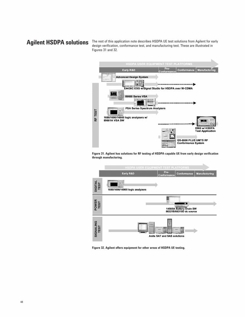
48
The rest of this application note describes HSDPA UE test solutions from Agilent for earlydesign verification, conformance test, and manufacturing test. These are illustrated inFigures 31 and 32.
Figure 31. Agilent has solutions for RF testing of HSDPA-capable UE from early design verificationthrough manufacturing.
Figure 32. Agilent offers equipment for other areas of HSDPA UE testing.
Agilent HSDPA solutions
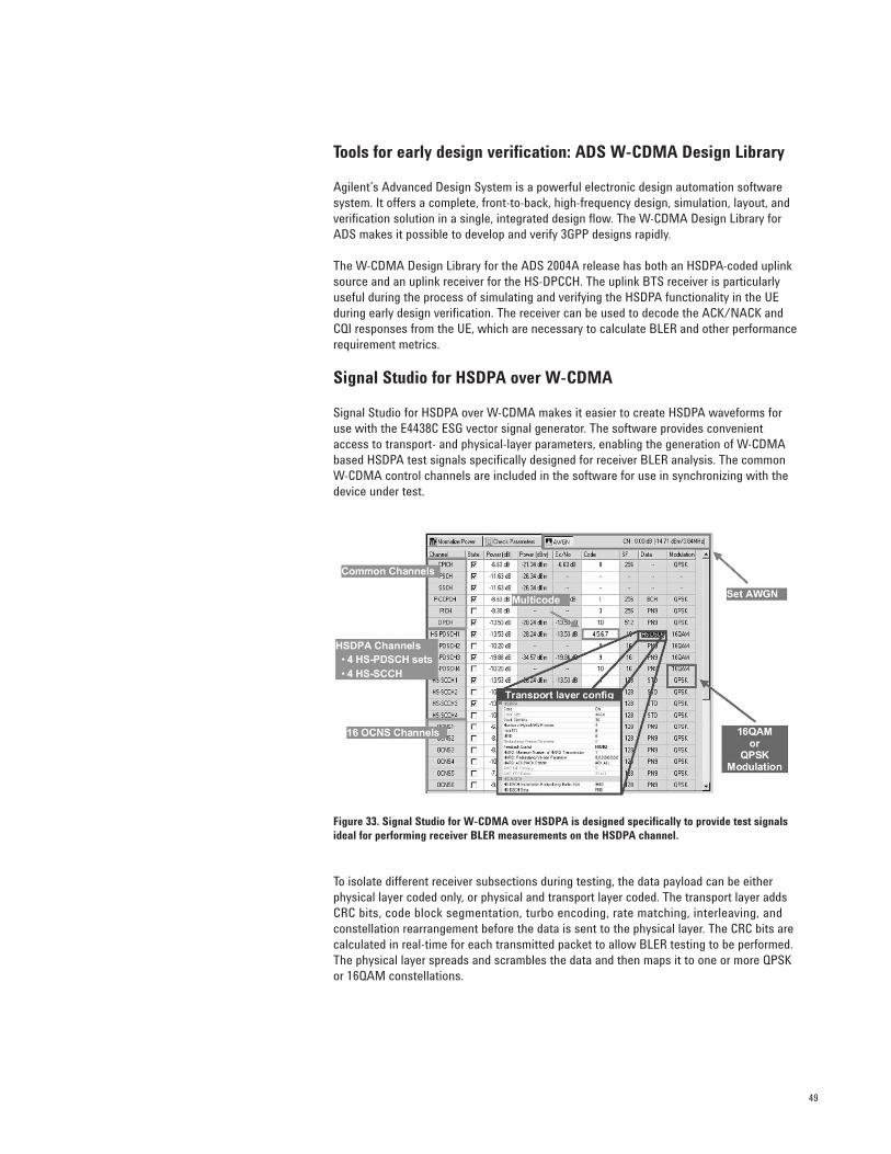
49
Tools for early design verification: ADS W-CDMA Design Library
Agilent’s Advanced Design System is a powerful electronic design automation softwaresystem. It offers a complete, front-to-back, high-frequency design, simulation, layout, andverification solution in a single, integrated design flow. The W-CDMA Design Library forADS makes it possible to develop and verify 3GPP designs rapidly.
The W-CDMA Design Library for the ADS 2004A release has both an HSDPA-coded uplinksource and an uplink receiver for the HS-DPCCH. The uplink BTS receiver is particularlyuseful during the process of simulating and verifying the HSDPA functionality in the UEduring early design verification. The receiver can be used to decode the ACK/NACK andCQI responses from the UE, which are necessary to calculate BLER and other performancerequirement metrics.
Signal Studio for HSDPA over W-CDMA
Signal Studio for HSDPA over W-CDMA makes it easier to create HSDPA waveforms foruse with the E4438C ESG vector signal generator. The software provides convenientaccess to transport- and physical-layer parameters, enabling the generation of W-CDMAbased HSDPA test signals specifically designed for receiver BLER analysis. The commonW-CDMA control channels are included in the software for use in synchronizing with thedevice under test.
Figure 33. Signal Studio for W-CDMA over HSDPA is designed specifically to provide test signalsideal for performing receiver BLER measurements on the HSDPA channel.
To isolate different receiver subsections during testing, the data payload can be eitherphysical layer coded only, or physical and transport layer coded. The transport layer addsCRC bits, code block segmentation, turbo encoding, rate matching, interleaving, and constellation rearrangement before the data is sent to the physical layer. The CRC bits arecalculated in real-time for each transmitted packet to allow BLER testing to be performed.The physical layer spreads and scrambles the data and then maps it to one or more QPSKor 16QAM constellations.
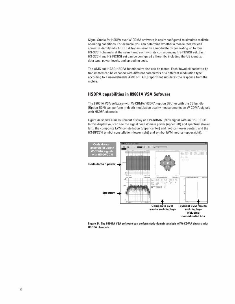
50
Signal Studio for HSDPA over W-CDMA software is easily configured to simulate realisticoperating conditions. For example, you can determine whether a mobile receiver can correctly identify which HSDPA transmission to demodulate by generating up to four HS-SCCH channels at the same time, each with its corresponding HS-PDSCH set. EachHS-SCCH and HS-PDSCH set can be configured differently, including the UE identity, data type, power levels, and spreading code.
The AMC and HARQ HSDPA functionality also can be tested. Each downlink packet to betransmitted can be encoded with different parameters or a different modulation typeaccording to a user-definable AMC or HARQ report that simulates the response from themobile.
HSDPA capabilities in 89601A VSA Software
The 89601A VSA software with W-CDMA/HSDPA (option B7U) or with the 3G bundle(Option B7N) can perform in-depth modulation quality measurements on W-CDMA signalswith HSDPA channels.
Figure 34 shows a measurement display of a W-CDMA uplink signal with an HS-DPCCH. In this display you can see the signal code domain power (upper left) and spectrum (lowerleft), the composite EVM constellation (upper center) and metrics (lower center), and theHS-DPCCH symbol constellation (lower right) and symbol EVM metrics (upper right).
Figure 34. The 89601A VSA software can perform code-domain analysis of W-CDMA signals withHSDPA channels.
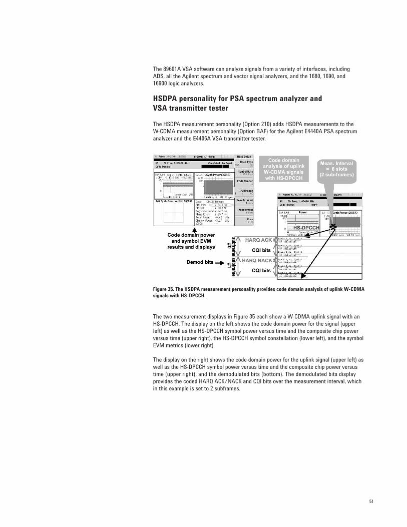
51
The 89601A VSA software can analyze signals from a variety of interfaces, including ADS, all the Agilent spectrum and vector signal analyzers, and the 1680, 1690, and 16900 logic analyzers.
HSDPA personality for PSA spectrum analyzer and VSA transmitter tester
The HSDPA measurement personality (Option 210) adds HSDPA measurements to the W-CDMA measurement personality (Option BAF) for the Agilent E4440A PSA spectrumanalyzer and the E4406A VSA transmitter tester.
Figure 35. The HSDPA measurement personality provides code domain analysis of uplink W-CDMAsignals with HS-DPCCH.
The two measurement displays in Figure 35 each show a W-CDMA uplink signal with anHS-DPCCH. The display on the left shows the code domain power for the signal (upperleft) as well as the HS-DPCCH symbol power versus time and the composite chip powerversus time (upper right), the HS-DPCCH symbol constellation (lower left), and the symbolEVM metrics (lower right).
The display on the right shows the code domain power for the uplink signal (upper left) aswell as the HS-DPCCH symbol power versus time and the composite chip power versustime (upper right), and the demodulated bits (bottom). The demodulated bits display provides the coded HARQ ACK/NACK and CQI bits over the measurement interval, whichin this example is set to 2 subframes.
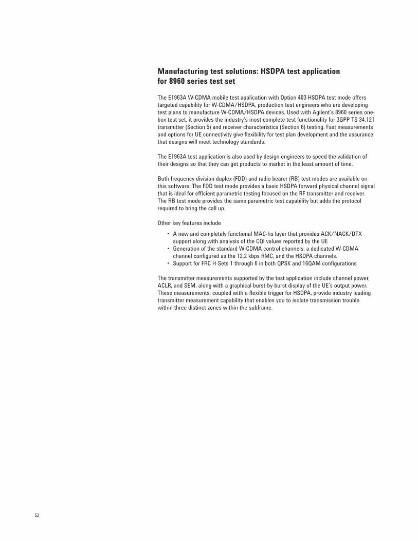
52
Manufacturing test solutions: HSDPA test application for 8960 series test set
The E1963A W-CDMA mobile test application with Option 403 HSDPA test mode offerstargeted capability for W-CDMA/HSDPA, production test engineers who are developingtest plans to manufacture W-CDMA/HSDPA devices. Used with Agilent’s 8960 series one-box test set, it provides the industry’s most complete test functionality for 3GPP TS 34.121transmitter (Section 5) and receiver characteristics (Section 6) testing. Fast measurementsand options for UE connectivity give flexibility for test plan development and the assurancethat designs will meet technology standards.
The E1963A test application is also used by design engineers to speed the validation oftheir designs so that they can get products to market in the least amount of time.
Both frequency division duplex (FDD) and radio bearer (RB) test modes are available onthis software. The FDD test mode provides a basic HSDPA forward physical channel signalthat is ideal for efficient parametric testing focused on the RF transmitter and receiver.The RB test mode provides the same parametric test capability but adds the protocolrequired to bring the call up.
Other key features include
• A new and completely functional MAC-hs layer that provides ACK/NACK/DTX support along with analysis of the CQI values reported by the UE
• Generation of the standard W-CDMA control channels, a dedicated W-CDMA channel configured as the 12.2 kbps RMC, and the HSDPA channels.
• Support for FRC H-Sets 1 through 6 in both QPSK and 16QAM configurations
The transmitter measurements supported by the test application include channel power,ACLR, and SEM, along with a graphical burst-by-burst display of the UE’s output power.These measurements, coupled with a flexible trigger for HSDPA, provide industry leadingtransmitter measurement capability that enables you to isolate transmission trouble within three distinct zones within the subframe.
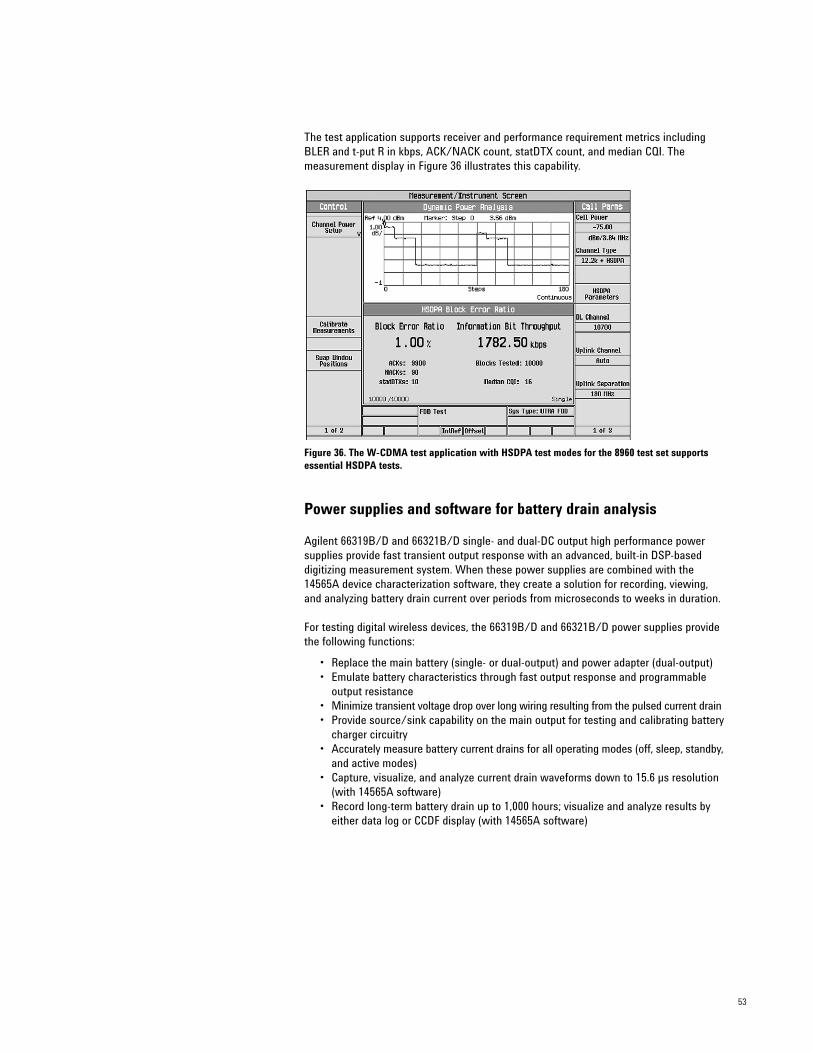
53
The test application supports receiver and performance requirement metrics includingBLER and t-put R in kbps, ACK/NACK count, statDTX count, and median CQI. The measurement display in Figure 36 illustrates this capability.
Figure 36. The W-CDMA test application with HSDPA test modes for the 8960 test set supportsessential HSDPA tests.
Power supplies and software for battery drain analysis
Agilent 66319B/D and 66321B/D single- and dual-DC output high performance powersupplies provide fast transient output response with an advanced, built-in DSP-baseddigitizing measurement system. When these power supplies are combined with the14565A device characterization software, they create a solution for recording, viewing,and analyzing battery drain current over periods from microseconds to weeks in duration.
For testing digital wireless devices, the 66319B/D and 66321B/D power supplies providethe following functions:
• Replace the main battery (single- or dual-output) and power adapter (dual-output)• Emulate battery characteristics through fast output response and programmable
output resistance• Minimize transient voltage drop over long wiring resulting from the pulsed current drain• Provide source/sink capability on the main output for testing and calibrating battery
charger circuitry• Accurately measure battery current drains for all operating modes (off, sleep, standby,
and active modes)• Capture, visualize, and analyze current drain waveforms down to 15.6 µs resolution
(with 14565A software)• Record long-term battery drain up to 1,000 hours; visualize and analyze results by
either data log or CCDF display (with 14565A software)

54
Pre-conformance and conformance RF test solutions
The GS-8800 is an RF design verification system for multiple radio technologies. It supportsW-CDMA, HSDPA, GSM, GPRS, EGPRS, cdma2000, 1xEVDO, and AMPS on a single hard-ware (8960 series) and software platform.
Based on this platform, the GS-8800 plus is a W-CDMA/HSDPA RF conformance systemthat supports the 3GPP TS 34.121 UE RF conformance test cases in Release 5. The GS-8800plus enhances the standard system with baseband processors and other instruments usedin conformance testing. These are located within the dotted lines in the block diagramshown in Figure 37.
Figure 37. GS-8800 standard and plus systems.
Two configurations are available for GS-8800 plus system. The first is the plus1 system for W-CDMA/HSDPA RF pre-conformance testing. The system is called “pre-compliance”because it limits test coverage to those cases that require only one 8960 test set in the system.
Signalanalysis
(E4445A PSA)
Out-of-bandinterference
(E8257D PSG)
In-bandinterference
(E4438C #1 ESG)
RF communicationstest set
(8960 #1 OBT)
Power supply(66311B)
RF fading simulatorwith AWGN
DUTRF
RF interface(N1961A)
GSM filter module(N1962A)
ATT/SW driver(87130A)
PC controller
In-bandinterference
(E4438C #2 ESG)
RF communications test set
(8960 #3 OBT)
Add-on RFinterface
BB processor(master)
BB processor(slave)
GS-8800 plus additional instruments
RF communicationstest set
(8960 #2 OBT)

Section Test description
5.2A Maximum output power with HS-DPCCH
5.9A Spectrum emission mask with HS-DPCCH
5.10A Adjacent channel leakage power ratio (ACLR) with HS-DPCCH
5.13.1A Error vector magnitude (EVM) with HS-DPCCH
6.3A Maximum input level for HS-PDSCH reception (16QAM)
9.2.1 Demodulation of HS-DSCH - single link performance
9.2.2 Demodulation of HS-DSCH - open loop diversity performance
9.2.3 Demodulation of HS-DSCH - closed loop diversity performance
9.3.1 Reporting of channel quality indicator - AWGN propagation conditions
9.3.2 Reporting of channel quality indicator - fading propagation conditions
9.4 HS-SCCH detection performance
Standard system
plus 1
plus 1
plus 2
plus system
GS-8800 TS 34.121 HSDPA tests
55
A second configuration, the plus2 system, is an RF conformance test system for W-CDMAand HSDPA. The system includes open loop and closed loop diversity test cases. SeeFigure 38.
Figure 38. The HSDPA test cases supported by the GS-8800 standard, plus1, and plus2 systems.
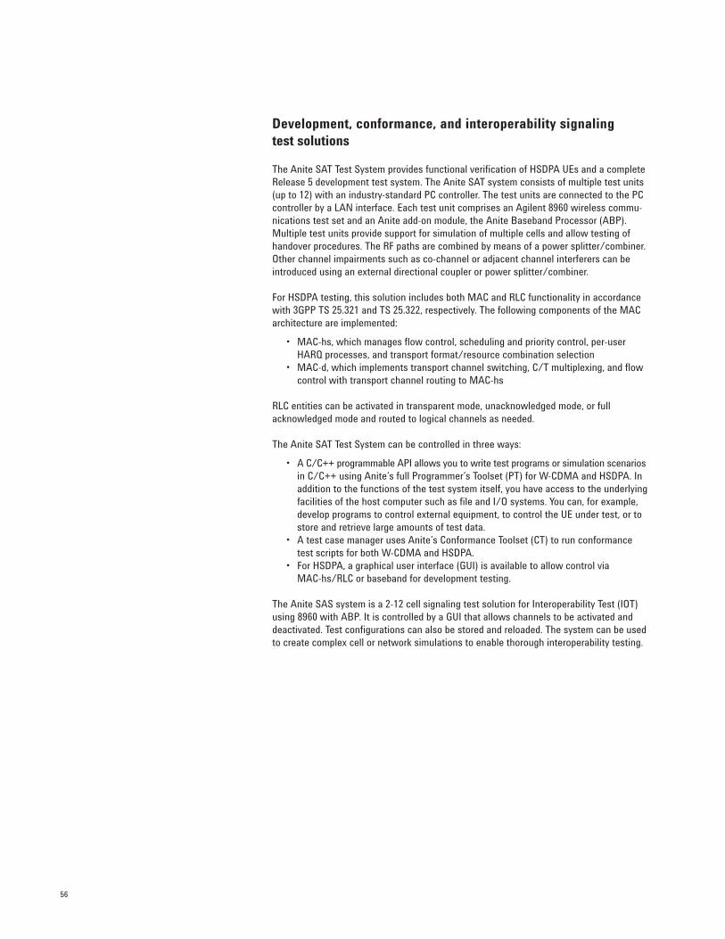
56
Development, conformance, and interoperability signaling test solutions
The Anite SAT Test System provides functional verification of HSDPA UEs and a completeRelease 5 development test system. The Anite SAT system consists of multiple test units(up to 12) with an industry-standard PC controller. The test units are connected to the PCcontroller by a LAN interface. Each test unit comprises an Agilent 8960 wireless commu-nications test set and an Anite add-on module, the Anite Baseband Processor (ABP).Multiple test units provide support for simulation of multiple cells and allow testing ofhandover procedures. The RF paths are combined by means of a power splitter/combiner.Other channel impairments such as co-channel or adjacent channel interferers can beintroduced using an external directional coupler or power splitter/combiner.
For HSDPA testing, this solution includes both MAC and RLC functionality in accordancewith 3GPP TS 25.321 and TS 25.322, respectively. The following components of the MACarchitecture are implemented:
• MAC-hs, which manages flow control, scheduling and priority control, per-user HARQ processes, and transport format/resource combination selection
• MAC-d, which implements transport channel switching, C/T multiplexing, and flow control with transport channel routing to MAC-hs
RLC entities can be activated in transparent mode, unacknowledged mode, or fullacknowledged mode and routed to logical channels as needed.
The Anite SAT Test System can be controlled in three ways:
• A C/C++ programmable API allows you to write test programs or simulation scenarios in C/C++ using Anite’s full Programmer’s Toolset (PT) for W-CDMA and HSDPA. In addition to the functions of the test system itself, you have access to the underlyingfacilities of the host computer such as file and I/O systems. You can, for example, develop programs to control external equipment, to control the UE under test, or to store and retrieve large amounts of test data.
• A test case manager uses Anite’s Conformance Toolset (CT) to run conformance test scripts for both W-CDMA and HSDPA.
• For HSDPA, a graphical user interface (GUI) is available to allow control via MAC-hs/RLC or baseband for development testing.
The Anite SAS system is a 2-12 cell signaling test solution for Interoperability Test (IOT)using 8960 with ABP. It is controlled by a GUI that allows channels to be activated anddeactivated. Test configurations can also be stored and reloaded. The system can be usedto create complex cell or network simulations to enable thorough interoperability testing.
57
Several aspects of HSDPA technology affect UE functionality and performance. TheHSDPA conformance tests that have been added to Release 5 and Release 6 of the 3GPPspecifications address the main areas that require testing.
New transmitter tests verify that the UE meets the reduced maximum output powerrequirements when the HS-DPCCH is added, and that the uplink ACLR, SEM, and EVM per-formance at this reduced maximum output power does not degrade significantly. A powerversus time mask has been introduced to verify the accuracy of the power steps caused bythe addition of the HS-DPCCH.
A new receiver test verifies that the UE can demodulate high-power downlink channelswith 16QAM.
The new HSDPA performance requirements tests cover three main areas that addresssome of the most challenging aspects of the new HSDPA functions:
• HS-DSCH decoding (including the multi-code demodulation capability and the HARQ functions—such as the IR combining—that take place during the decoding process)
• CQI reporting• Detection of the HS-SCCH
To meet a wide range of development needs, Agilent provides HSDPA solutions that testUE from early design verification through manufacturing.
Summary
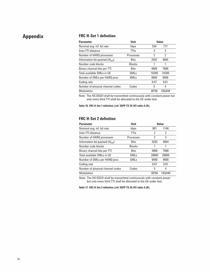
58
FRC H-Set 1 definition
Table 16. FRC H-Set 1 definition (ref: 3GPP TS 25.101 table A.25).
FRC H-Set 2 definition
Table 17. FRC H-Set 2 definition (ref: 3GPP TS 25.101 table A.26).
AppendixParameter Unit Value
Nominal avg. inf. bit rate kbps 534 777
Inter-TTI distance TTIs 3 3
Number of HARQ processes Processes 2 2
Information bit payload (NINF) Bits 3202 4664
Number code blocks Blocks 1 1
Binary channel bits per TTI Bits 4800 7680
Total available SMLs in UE SMLs 19200 19200
Number of SMLs per HARQ proc. SMLs 9600 9600
Coding rate 0.67 0.61
Number of physical channel codes Codes 5 4
Modulation QPSK 16QAM
Note: The HS-DSCH shall be transmitted continuously with constant power but only every third TTI shall be allocated to the UE under test.
Parameter Unit Value
Nominal avg. inf. bit rate kbps 801 1166
Inter-TTI distance TTIs 2 2
Number of HARQ processes Processes 3 3
Information bit payload (NINF) Bits 3202 4664
Number code blocks Blocks 1 1
Binary channel bits per TTI Bits 4800 7680
Total available SMLs in UE SMLs 28800 28800
Number of SMLs per HARQ proc. SMLs 9600 9600
Coding rate 0.67 0.61
Number of physical channel codes Codes 5 4
Modulation QPSK 16QAM
Note: The HS-DSCH shall be transmitted continuously with constant power but only every third TTI shall be allocated to the UE under test.
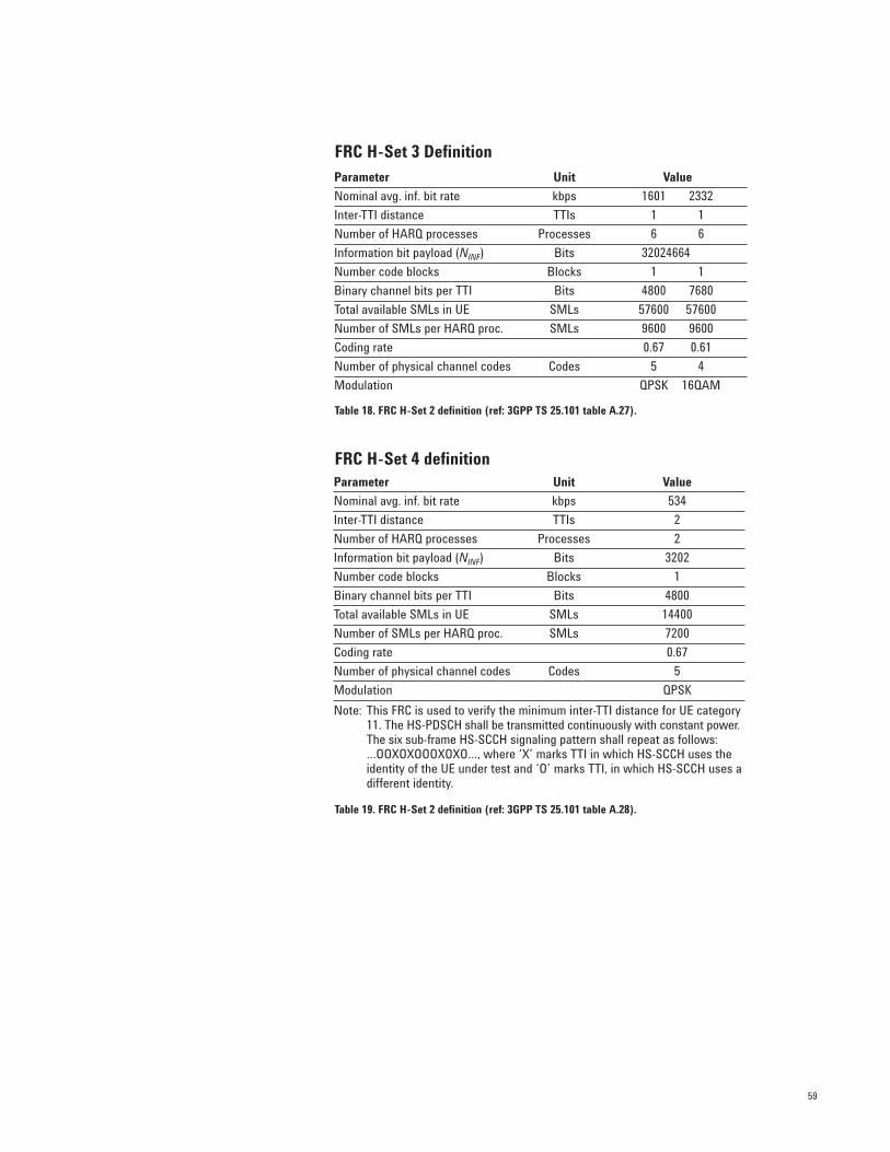
59
FRC H-Set 3 Definition
Table 18. FRC H-Set 2 definition (ref: 3GPP TS 25.101 table A.27).
FRC H-Set 4 definition
Table 19. FRC H-Set 2 definition (ref: 3GPP TS 25.101 table A.28).
Parameter Unit Value
Nominal avg. inf. bit rate kbps 534
Inter-TTI distance TTIs 2
Number of HARQ processes Processes 2
Information bit payload (NINF) Bits 3202
Number code blocks Blocks 1
Binary channel bits per TTI Bits 4800
Total available SMLs in UE SMLs 14400
Number of SMLs per HARQ proc. SMLs 7200
Coding rate 0.67
Number of physical channel codes Codes 5
Modulation QPSK
Note: This FRC is used to verify the minimum inter-TTI distance for UE category11. The HS-PDSCH shall be transmitted continuously with constant power.The six sub-frame HS-SCCH signaling pattern shall repeat as follows:…OOXOXOOOXOXO…, where ‘X’ marks TTI in which HS-SCCH uses theidentity of the UE under test and ‘O’ marks TTI, in which HS-SCCH uses adifferent identity.
Parameter Unit Value
Nominal avg. inf. bit rate kbps 1601 2332
Inter-TTI distance TTIs 1 1
Number of HARQ processes Processes 6 6
Information bit payload (NINF) Bits 32024664
Number code blocks Blocks 1 1
Binary channel bits per TTI Bits 4800 7680
Total available SMLs in UE SMLs 57600 57600
Number of SMLs per HARQ proc. SMLs 9600 9600
Coding rate 0.67 0.61
Number of physical channel codes Codes 5 4
Modulation QPSK 16QAM
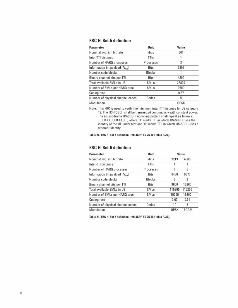
60
FRC H-Set 5 definition
Table 20. FRC H-Set 2 definition (ref: 3GPP TS 25.101 table A.29).
FRC H-Set 6 definition
Table 21. FRC H-Set 2 definition (ref: 3GPP TS 25.101 table A.30).
Parameter Unit Value
Nominal avg. inf. bit rate kbps 801
Inter-TTI distance TTIs 1
Number of HARQ processes Processes 3
Information bit payload (NINF) Bits 3202
Number code blocks Blocks 1
Binary channel bits per TTI Bits 4800
Total available SMLs in UE SMLs 28800
Number of SMLs per HARQ proc. SMLs 9600
Coding rate 0.67
Number of physical channel codes Codes 5
Modulation QPSK
Note: This FRC is used to verify the minimum inter-TTI distance for UE category12. The HS-PDSCH shall be transmitted continuously with constant power.The six sub-frame HS-SCCH signalling pattern shall repeat as follows:…OOXXXOOOXXXO…, where ‘X’ marks TTI in which HS-SCCH uses the identity of the UE under test and ‘O’ marks TTI, in which HS-SCCH uses adifferent identity.
Parameter Unit Value
Nominal avg. inf. bit rate kbps 3219 4689
Inter-TTI distance TTIs 1 1
Number of HARQ processes Processes 6 6
Information bit payload (NINF) Bits 6438 9377
Number code blocks Blocks 2 2
Binary channel bits per TTI Bits 9600 15360
Total available SMLs in UE SMLs 115200 115200
Number of SMLs per HARQ proc. SMLs 19200 19200
Coding rate 0.67 0.61
Number of physical channel codes Codes 10 8
Modulation QPSK 16QAM
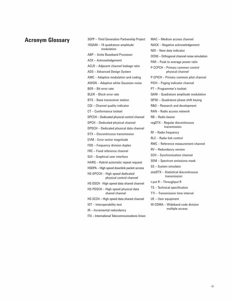
61
3GPP – Third Generation Partnership Project
16QAM – 16 quadrature amplitude modulation
ABP – Anite Baseband Processor
ACK – Acknowledgement
ACLR – Adjacent channel leakage ratio
ADS – Advanced Design System
AMC – Adaptive modulation and coding
AWGN – Adaptive white Gaussian noise
BER – Bit error rate
BLER – Block error rate
BTS – Base transceiver station
CQI – Channel quality indicator
CT – Conformance toolset
DPCCH – Dedicated physical control channel
DPCH – Dedicated physical channel
DPDCH – Dedicated physical data channel
DTX – Discontinuous transmission
EVM – Error vector magnitude
FDD – Frequency division duplex
FRC – Fixed reference channel
GUI – Graphical user interface
HARQ – Hybrid automatic repeat request
HSDPA – High speed downlink packet access
HS-DPCCH – High speed dedicated physical control channel
HS-DSCH - High speed data shared channel
HS-PDSCH – High speed physical data shared channel
HS-SCCH – High speed data shared channel
IOT – Interoperability test
IR – Incremental redundancy
ITU – International Telecommunications Union
MAC – Medium access channel
NACK – Negative acknowledgement
NDI – New data indicator
OCNS – Orthogonal channel noise simulation
PAR – Peak-to-average power ratio
P-CCPCH – Primary common control physical channel
P-CPICH – Primary common pilot channel
PICH – Paging indicator channel
PT – Programmer’s toolset
QAM – Quadrature amplitude modulation
QPSK – Quadrature phase shift keying
R&D – Research and development
RAN – Radio access network
RB – Radio bearer
regDTX – Regular discontinuous transmission
RF – Radio frequency
RLC – Radio link control
RMC – Reference measurement channel
RV – Redundancy version
SCH – Synchronization channel
SEM – Spectrum emissions mask
SS – System simulator
statDTX – Statistical discontinuous transmission
t-put R – Throughput R
TS – Technical specification
TTI – Transmission time interval
UE – User equipment
W-CDMA – Wideband code division multiple access
Acronym Glossary
62
3GPP TS 25.101 V.6.9.0UE Radio Transmission and Reception (FDD)
3GPP TS 34.121 V.6.2.0Terminal Conformance Specification. Radio Transmission and Reception (FDD)
3GPP TS 25.211 V.5.7.0Physical Channels and Mapping of Transport Channels onto Physical Channels (FDD)
3GPP TS 25.212 V.5.a.0Multiplexing and Channel Coding (FDD)
3GPP TS 25.213 V.5.6.0Spreading and Modulation (FDD)
3GPP TS 25.214 V.5.b.0Physical Layer Procedures (FDD)
3GPP TS 25.306 V.5.c.0UE Radio Access Capabilities
3GPP TS 25.308 V.5.7.0HSDPA Overall Description
3GPP TS 25.321 V.5.c.0Medium Access Control (MAC) Protocol Specification
3GPP TR 25.858 V.5.0.0High Speed Downlink Packet Access Physical Layer Aspects
3GPP TR 25.877 V.5.1.0High Speed Downlink Packet Access: lub/lur Protocol Aspects
3GPP TR 25.950 V.4.0.0UTRA High Speed Downlink Packet Access
Reference SpecificationDocuments (www.3gpp.org)
63
[1] 3GPP R4-021607, UE maximum output power with HS-DPCCH, Nokia
[2] 3GPP R4-030796, ACLR requirements under HSDPA operation, Sony Ericsson Mobile Communications
[3] 3GPP R4-031037, PAR increase of UE transmit signal with HS-DPCCH
Information on Agilent’s HSDPA solutions: www.agilent.com/find/hsdpa
Concepts of High Speed Downlink Packet Access: Bringing Increased Throughput andEfficiency to W-CDMA, application note, Agilent literature number 5989-2365EN
Designing and Testing 3GPP W-CDMA User Equipment, application note 1356, Agilent literature number 5980-1238E
HSDPA in the Agilent Technologies 8960 Wireless Communications Test Set, application note, Agilent literature number 5989-3444EN
Additional References(www.3gpp.org)
Related Information
Agilent Email Updates
Agilent Direct
AgilentOpen
Remove all doubt
Our repair and calibration services will get
your equipment back to you, performing
like new, when promised. You will get
full value out of your Agilent equipment
throughout its lifetime. Your equipment
will be serviced by Agilent-trained techni-
cians using the latest factory calibration
procedures, automated repair diagnostics
and genuine parts. You will always have the
utmost confidence in your measurements.
Agilent offers a wide range of additional
expert test and measurement services for
your equipment, including initial start-up
assistance onsite education and training,
as well as design, system integration, and
project management.
For more information on repair and
calibration services, go to
www.agilent.com/find/removealldoubt
www.agilent.com
For more information on Agilent
Technologies’ products, applications
or services, please contact your local
Agilent office. The complete list is
available at:
www.agilent.com/find/contactus
Phone or Fax
United States:(tel) 800 829 4444(fax) 800 829 4433
Canada:(tel) 877 894 4414(fax) 800 746 4866
China:(tel) 800 810 0189(fax) 800 820 2816
Europe:(tel) 31 20 547 2111
Japan:(tel) (81) 426 56 7832(fax) (81) 426 56 7840
Korea:(tel) (080) 769 0800(fax) (080) 769 0900
Latin America:(tel) (305) 269 7500
Taiwan:(tel) 0800 047 866 (fax) 0800 286 331
Other Asia Pacific Countries:(tel) (65) 6375 8100 (fax) (65) 6755 0042Email: [email protected]: 11/08/06
Product specifications and descriptions
in this document subject to change
without notice.
© Agilent Technologies, Inc. 2005, 2007
Printed in USA, January 18, 2007
5989-4099EN
www.agilent.com/find/emailupdates
Get the latest information on the products
and applications you select.
www.agilent.com/find/agilentdirect
Quickly choose and use your test
equipment solutions with confidence.
www.agilent.com/find/open
Agilent Open simplifies the process of
connecting and programming test systems
to help engineers design, validate and
manufacture electronic products. Agilent
offers open connectivity for a broad range
of system-ready instruments, open industry
software, PC-standard I/O and global sup-
port, which are combined to more easily
integrate test system development.