Embed Size (px)
Citation preview
DATA SHEET
AGENT STORAGE CONTAINERS WITH ECARO-25®ECARO-25 is also known by its ASHRAE designation HFC-125
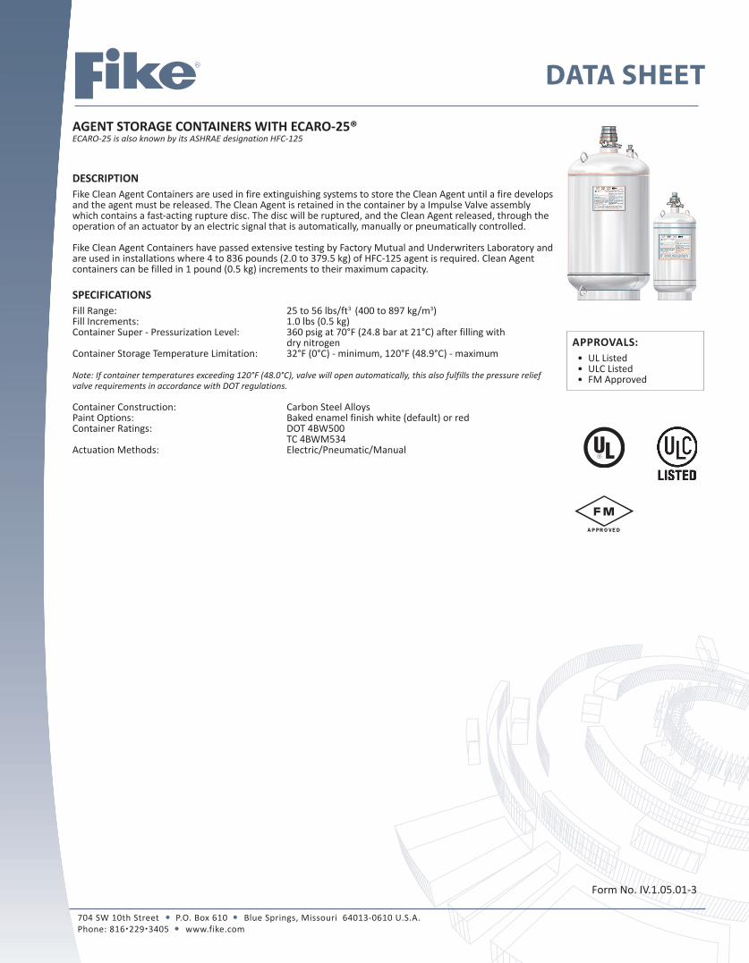
DESCRIPTIONFike Clean Agent Containers are used in fire extinguishing systems to store the Clean Agent until a fire develops and the agent must be released. The Clean Agent is retained in the container by a Impulse Valve assembly which contains a fast-acting rupture disc. The disc will be ruptured, and the Clean Agent released, through the operation of an actuator by an electric signal that is automatically, manually or pneumatically controlled.
Fike Clean Agent Containers have passed extensive testing by Factory Mutual and Underwriters Laboratory and are used in installations where 4 to 836 pounds (2.0 to 379.5 kg) of HFC-125 agent is required. Clean Agent containers can be filled in 1 pound (0.5 kg) increments to their maximum capacity.
SPECIFICATIONSFill Range: 25 to 56 lbs/ft3 (400 to 897 kg/m3)Fill Increments: 1.0 lbs (0.5 kg)Container Super - Pressurization Level: 360 psig at 70°F (24.8 bar at 21°C) after filling with dry nitrogen Container Storage Temperature Limitation: 32°F (0°C) - minimum, 120°F (48.9°C) - maximum
Note: If container temperatures exceeding 120°F (48.0°C), valve will open automatically, this also fulfills the pressure relief valve requirements in accordance with DOT regulations.
Container Construction: Carbon Steel AlloysPaint Options: Baked enamel finish white (default) or redContainer Ratings: DOT 4BW500 TC 4BWM534 Actuation Methods: Electric/Pneumatic/Manual
Form No. IV.1.05.01-3
704 SW 10th Street P.O. Box 610 Blue Springs, Missouri 64013-0610 U.S.A. Phone: 8162293405 www.fike.com
APPROVALS:• UL Listed• ULC Listed• FM Approved

2 of 7
CONTAINER DATA/SPECIFICATIONS
Container Fill rangeValve Size Tare Weight
Dimensions (approximate) Mounting
PositionSizeP/N
Minimum Maximum Diameter Height
Lb. (L) lbs. (kg) lbs. (kg) IN (mm) lbs. (kg) IN (mm) IN (mm)
5 (2) 70-272 4
(2.0)4
(2.0)1
(25)11
(5.0)4.2
(102)16.2
(411.5)Upright
(Valve Up)
10 (4) 70-273 4
(2.0)8
(3.5)1
(25)15
(6.8)4.2
(102)27.24
(691.9)Upright
(Valve Up)
20(8.5) 70-263 8
(3.5)16
(7.5)1
(25)22
(10.0)7.0
(178)22.50
(571.5)Upright -
Horizontal
35 (15) 70-264 14
(6.5)30
(13.5)1
(25)32.5
(14.7)7.0
(178)33.75
(857.3)Upright -
Horizontal
60(27) 70-265 25
(11.5)54
(24.5)1
(25)52.5
(23.8)10.75(273)
28.13(714.4)
Upright -Horizontal
100(44) 70-266 39
(18.0)87
(39.0)1
(25)77
(34.9)10.75(273)
39.63(1006.5)
Upright (Valve Up)
150/150i(61) 70-267 54
(24.5)120
(54.5)3
(80)118/114
(53.5/51.7)20.0 (508)
24.25(616.0) Upright/Inverted
215(88) 70-268 78
(35.5)173
(78.5)3
(80)146
(66.2)20.0(508)
30.13 (765.2)
Upright(Valve Up)
375(153) 70-269 136
(61.5)302
(137.0)3
(80)213
(96.6)20.0(508)
43.38(1101.7)
Upright(Valve Up)
650(267) 70-270 236
(107.0)528
(239.5)3
(80)373
(169.2)24.0 (610)
50.50(1282.7)
Upright (Valve Up)
1000(423) 70-271 374
(169.5)836
(379.5)3
(80)535
(242.7)24.0(610)
71.88(1825.6)
Upright(Valve Up)

3 of 7
ITEMS SUPPLIED WITH CONTAINER ASSEMBLY
Item Number Description Data Sheet
1 Victaulic Coupling & Nipple IV.1.19.01
2 Impulse Valve IV.1.14.01
3 Pressure Gauge IV.1.13.01
4 Liquid Level Indicator (LLi) C.1.40.01
5 LLi Boss (see note 1) n/a
6 Nameplate (see note 2) n/a
7 Siphone Tube (see note 3) n/a
8 Mounting Straps & Brackets IV.1.18.01 Notes:1) 100 thru 1000 lb. (44 thru 423 L) containers are equipped with a LLi Boss.
2) Fike nameplate provides the information that is specific to each container: Assembly and serial number of the container, weight information: tare, gross and agent and installation, operation and safety information. All containers filled either by the factory or by an Approved Initial Fill Station are provided with a name plate bearing the UL & FM markings.
3) Fike Clean Agent containers [except the 150i (Inverted)] are equipped with a siphon tube. The 20, 35 & 60 lb. containers have bent siphon tubes and the 5, 10 and 100 – 1000 lb. containers have straight siphon tubes. All containers with siphon tubes can be mounted upright. The 20, 35 & 60 lb containers can also be mounted horizontally. The 150 container can only be mounted upright and the 150i can only be mounted inverted.

4 of 7
OPTIONAL ITEMS FOR CONTAINERThe following container accessory items must be ordered separately.
ACTUATION COMPONENTS• Electric / Manual Actuation – Impulse Valve Operator (IVO) (For detailed information, refer to the IVO Data Sheet IV.1.09.01)
• Pneumatic Actuation – Impulse Valve Pneumatic Operator (IVPO) (For detailed information, refer to the IVPO Data Sheet IV.1.10.01)
ACTUATION METHODSClean Agent containers with an Impulse Valve can be actuated by the following methods:
• Method 1 – Electric Actuation – Single Container System w/ IVO & IRM• Method 2 – Electric Actuation – Multi-Containers System w / IVO & IRM• Method 3 – Electric & Pneumatic Actuation – Two Container System w/ IVO & IVPO • Method 4 – Electric & Pneumatic Actuation – Multi Container System w/ IVO & IVPO
For detailed information on actuation methods, refer to the Impulse Valve Operator (IVO) data sheet IV.1.09.01. These devices provide the force required to extend a pin that will open the rupture disc, allowing the agent to be released from the container.
5 of 7
LOW PRESSURE SWITCHThe Low Pressure Switch provides a means to continuously monitoring the container pressure for a low-pressure condition.
If the pressure inside the container drops below 288 psig (1986 kPa), the switch contacts will transfer and invoke a “trouble” indication on the control panel.
The Low Pressure Switch (P/N 02-12533) has a single pole, double-throw switch that can be wired for normally open or normally closed.
For detailed information, refer to the Low Pressure Switch Data Sheet IV.1.13.01.
INSTALLATION The system installation must comply with the requirements of this manual; NFPA 2001, latest edition; all applicable local codes, regulations, and standards and the authority having jurisdiction (AHJ).
Warning: DO NOT start system installation until the final design of the total system has been verified using Fike’s Engineered Flow Calculation. Warning: The Actuator shall always be the last component installed on a Fike Clean Agent Fire Suppression system to avoid accidental discharge.
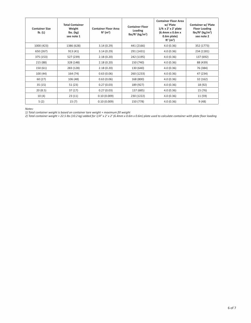
Factors to Consider - Container LocationMounting Surface: Container brackets must be mounted securely to solid load-bearing surfaces that will support the container load. Some installations may require additional mounting support not supplied by Fike.Environmental Effects: Container(s) should be located in clean, dry, and relatively vibration-free areas. Avoid aisle ways and other high traffic areas where physical damage or tampering is more likely. Container(s) should never be mounted where the container could potentially be splashed with, or submerged in any liquid. Do not locate containers where they would be subject to physical damage, exposure to corrosive chemicals, or harsh weather conditions.Temperature Range: Container locations must be between 32 to 120°F (0 to 48.9°C).Temperatures outside of this range may result in the system not supplying the desired quantity of agent or accidental discharge.Serviceability: In general, the larger the container, the more difficult it will be to remove it from the system for maintenance and service. However, smaller containers that are located in a sub-floor space, under a computer bank, or above the ceiling over the same computer bank can be difficult as well.Floor Space: Consideration should be given to the space available to install the container(s). For example, a 900 lb. (408 kg) system could be stored in (2) 650 lb. (267 L) containers located on the floor. However, if floor space is a problem, the system could be designed to utilize (6) 150i lb. (61 L) Inverted Containers mounted on the wall(s).Floor Loading: Floor loading must be considered when selecting a container location. The floor must be able to support the total weight of the Fike container(s) as they are moved into position. Consult raised floor manufacturer for floor loading limitation. The following guidelines are recommended: • Raised floor loading is a function of the manufacturer’s load specification and the positioning of the container(s) on the raised floor grid. Note: Fike cannot assume responsibility for determining the suitability of a particular raised floor system; the following does provide information to help determine installation requirements. • When clean agent containers are located on a raised floor, floor integrity must be considered to determine if the type of tile and vertical floor support can handle the increased load. If necessary additional floor supports can be added. Option: To help distribute the container weight over a greater area, a ¼” steel plate can be placed under the container(s), sized to span multiple floor supports. If container spans multiple floor tiles, add additional floor supports (Minimum of 4 floor supports, 1 per corner, must be used). Excessive floor loading may require relocating the container(s) to a more suitable location. For floor loading information refer to the table on page 6 or to Fike’s ECARO-25 Flow Calculation program for container size and actual fill weight being supplied.
6 of 7
Container Sizelb. (L)
Total Container Weight lbs. (kg)
see note 1
Container Floor Areaft2 (m2)
Container Floor Loading
lbs/ft2 (kg/m2)
Container Floor Area w/ Plate
1/4: x 2’ x 2’ plate(6.4mm x 0.6m x
0.6m plate) ft2 (m2)
Container w/ Plate Floor Loadinglbs/ft2 (kg/m2)
see note 2
1000 (423) 1386 (628) 3.14 (0.29) 441 (2166) 4.0 (0.36) 352 (1773)
650 (267) 913 (41) 3.14 (0.29) 291 (1431) 4.0 (0.36) 234 (1181)
375 (153) 527 (239) 2.18 (0.20) 242 (1195) 4.0 (0.36) 137 (692)
215 (88) 328 (148) 2.18 (0.20) 150 (740) 4.0 (0.36) 88 (439)
150 (61) 283 (128) 2.18 (0.20) 130 (640) 4.0 (0.36) 76 (384)
100 (44) 164 (74) 0.63 (0.06) 260 (1233) 4.0 (0.36) 47 (234)
60 (27) 106 (48) 0.63 (0.06) 168 (800) 4.0 (0.36) 32 (162)
35 (15) 51 (23) 0.27 (0.03) 189 (927) 4.0 (0.36) 18 (92)
20 (8.5) 37 (17) 0.27 (0.03) 137 (685) 4.0 (0.36) 15 (76)
10 (4) 23 (11) 0.10 (0.009) 230 (1222) 4.0 (0.36) 11 (59)
5 (2) 15 (7) 0.10 (0.009) 150 (778) 4.0 (0.36) 9 (48)
Notes:1) Total container weight is based on container tare weight + maximum fill weight2) Total container weight + 22.5 lbs (10.2 kg) added for 1/4” x 2’ x 2’ (6.4mm x 0.6m x 0.6m) plate used to calculate container with plate floor loading

Copyright © Fike Corporation All Rights Reserved.Form No. IV.1.05.01-3, February 2012. Specifications are subject to change without notice.
7 of 7
RECHARGE ITEMS – 1 IN (25) & 3 IN (80) VALVE (Must Order Separate)After a system has been discharged, the following items must be replaced before a container can be recharged. For a detailed procedure on recharging a Fike container with an Impulse Valve refer to Fike’s Recharge Manual (p/n 06-290).
Item Description
1 IN (25mm) Recharge Kit (P/N 85-047) includes the
following:
3 IN (80mm) Recharge Kit (P/N 85-048 includes the
following:
Part Number Part Number
1 Friction Ring 70-2060 70-2063
2 Disc Assembly 70-247 70-248
3 O-Ring 02-11987 02-11989
4 Valve Core-Fill Port (not shown) 02-4161 02-4161
5 Reconditioning Instructions (not shown) 06-567 Note: 1 IN Recharge Kit is used on 5, 10, 20, 35, 60 & 100 lb. (2, 4, 8, 15, 27 & 44 L) containers 3 IN Recharge Kit is used on 150, 150i, 215, 375, 650 & 1000 lb. (61, 61i, 88, 153, 267 & 423 L) containers