Embed Size (px)
Citation preview
Tube Axial FanPage
Introduction . . . . . . . . . . . . . . . . . . . . . . . . . . . . . . . . . . . . . . . . . . . 2Construction Features . . . . . . . . . . . . . . . . . . . . . . . . . . . . . . . . . . . 3Information . . . . . . . . . . . . . . . . . . . . . . . . . . . . . . . . . . . . . . . . . . . 4Specifications & Dimension Data AFD-C (Tube Axial Fan Direct Drive) . . . . . . . . . . . . . . . . . . . . . . . 5AFB-C (Tube Axial Fan Belt Drive) . . . . . . . . . . . . . . . . . . . . . . . . . 6AFB-H (Tube Axial Fan High Temperature Belt Drive) . . . . . . . . . . 7AFB-S (Tube Axial Fan Stainless Steel Belt Drive) . . . . . . . . . . . . . 8Accessories . . . . . . . . . . . . . . . . . . . . . . . . . . . . . . . . . . . . . . . 9 - 10Performance Data AFD-C and AFDV-C . . . . . . . . . . . . . . . . . . . . . . . . . . . . . . . . . . . 1112 -60 AFB-C / AFBV-C. . . . . . . . . . . . . . . . . . . . . . . . . . . . . . 12-2212 -36 AFB-H / AFB-S / AFBV-H / AFBV-S . . . . . . . . . . . . . . . 23-31Air Density and Temperature Factors . . . . . . . . . . . . . . . . . . . . . . 32
2
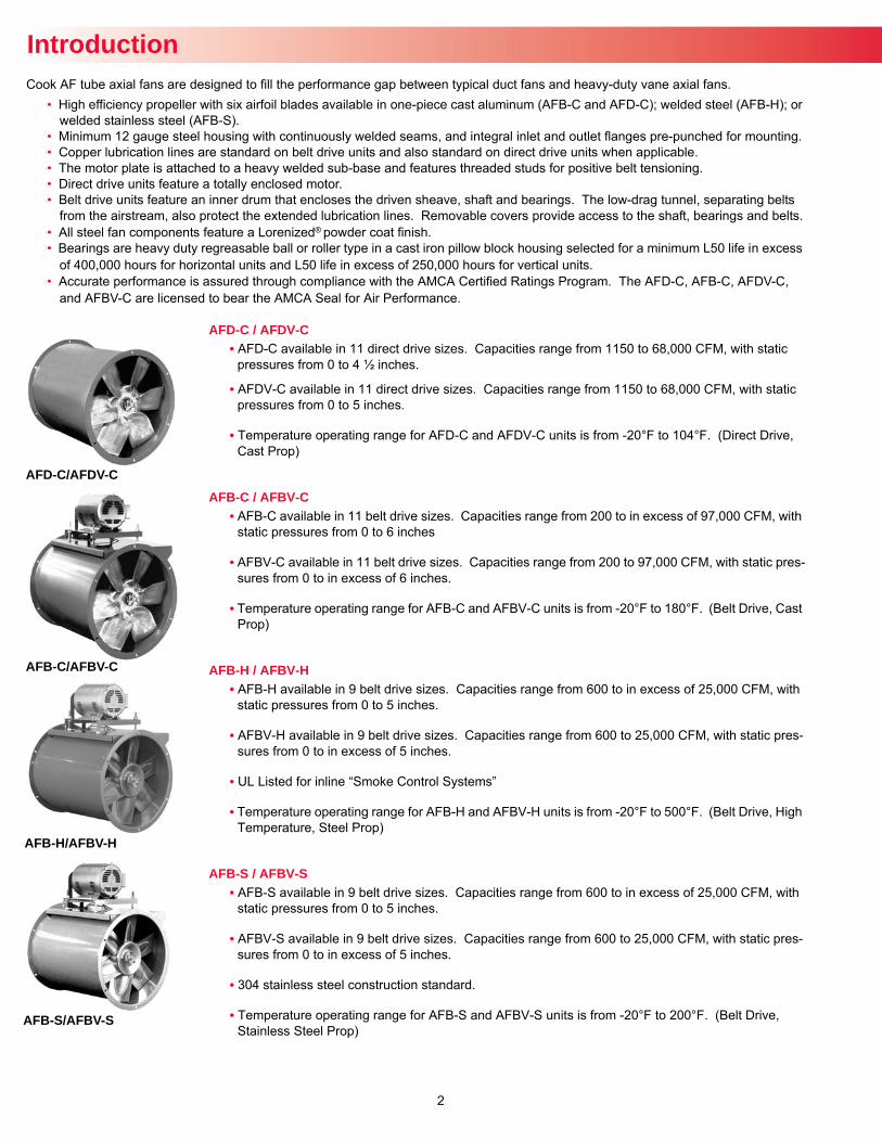
AFD-C / AFDV-C• AFD-C available in 11 direct drive sizes. Capacities range from 1150 to 68,000 CFM, with static
pressures from 0 to 4 ½ inches.
• AFDV-C available in 11 direct drive sizes. Capacities range from 1150 to 68,000 CFM, with static pressures from 0 to 5 inches.
• Temperature operating range for AFD-C and AFDV-C units is from -20°F to 104°F. (Direct Drive, Cast Prop)
AFB-C / AFBV-C• AFB-C available in 11 belt drive sizes. Capacities range from 200 to in excess of 97,000 CFM, with
static pressures from 0 to 6 inches
• AFBV-C available in 11 belt drive sizes. Capacities range from 200 to 97,000 CFM, with static pres-sures from 0 to in excess of 6 inches.
• Temperature operating range for AFB-C and AFBV-C units is from -20°F to 180°F. (Belt Drive, Cast Prop)
AFB-H / AFBV-H• AFB-H available in 9 belt drive sizes. Capacities range from 600 to in excess of 25,000 CFM, with
static pressures from 0 to 5 inches.
• AFBV-H available in 9 belt drive sizes. Capacities range from 600 to 25,000 CFM, with static pres-sures from 0 to in excess of 5 inches.
• UL Listed for inline “Smoke Control Systems”
• Temperature operating range for AFB-H and AFBV-H units is from -20°F to 500°F. (Belt Drive, High Temperature, Steel Prop)
AFB-S / AFBV-S• AFB-S available in 9 belt drive sizes. Capacities range from 600 to in excess of 25,000 CFM, with
static pressures from 0 to 5 inches.
• AFBV-S available in 9 belt drive sizes. Capacities range from 600 to 25,000 CFM, with static pres-sures from 0 to in excess of 5 inches.
• 304 stainless steel construction standard.
• Temperature operating range for AFB-S and AFBV-S units is from -20°F to 200°F. (Belt Drive, Stainless Steel Prop)
Introduction
AFD-C/AFDV-C
AFB-C/AFBV-C
AFB-S/AFBV-S
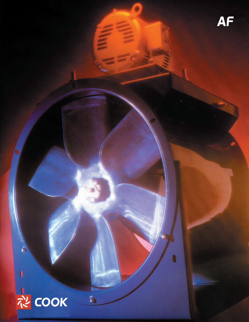
Cook AF tube axial fans are designed to fill the performance gap between typical duct fans and heavy-duty vane axial fans.• High efficiency propeller with six airfoil blades available in one-piece cast aluminum (AFB-C and AFD-C); welded steel (AFB-H); or
welded stainless steel (AFB-S).• Minimum 12 gauge steel housing with continuously welded seams, and integral inlet and outlet flanges pre-punched for mounting.• Copper lubrication lines are standard on belt drive units and also standard on direct drive units when applicable.• The motor plate is attached to a heavy welded sub-base and features threaded studs for positive belt tensioning.• Direct drive units feature a totally enclosed motor.• Belt drive units feature an inner drum that encloses the driven sheave, shaft and bearings. The low-drag tunnel, separating belts
from the airstream, also protect the extended lubrication lines. Removable covers provide access to the shaft, bearings and belts.• All steel fan components feature a Lorenized® powder coat finish.• Bearings are heavy duty regreasable ball or roller type in a cast iron pillow block housing selected for a minimum L50 life in excess
of 400,000 hours for horizontal units and L50 life in excess of 250,000 hours for vertical units. • Accurate performance is assured through compliance with the AMCA Certified Ratings Program. The AFD-C, AFB-C, AFDV-C,
and AFBV-C are licensed to bear the AMCA Seal for Air Performance.
AFB-H/AFBV-H
3
Construction Features
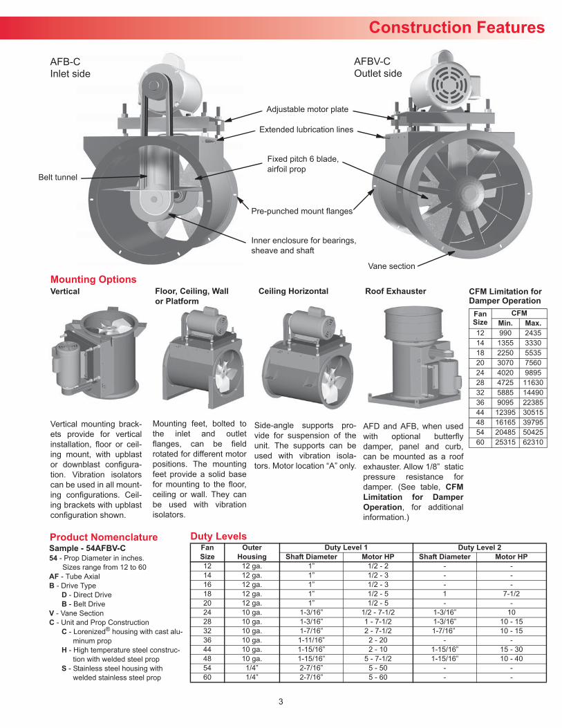
Side-angle supports pro-vide for suspension of theunit. The supports can beused with vibration isola-tors. Motor location “A” only.
Roof ExhausterMounting OptionsVertical Floor, Ceiling, Wall
or PlatformCeiling Horizontal
Vertical mounting brack-ets provide for verticalinstallation, floor or ceil-ing mount, with upblastor downblast configura-tion. Vibration isolatorscan be used in all mount-ing configurations. Ceil-ing brackets with upblastconfiguration shown.
Mounting feet, bolted tothe inlet and outletflanges, can be fieldrotated for different motorpositions. The mountingfeet provide a solid basefor mounting to the floor,ceiling or wall. They canbe used with vibrationisolators.
AFD and AFB, when usedwith optional butterflydamper, panel and curb,can be mounted as a roofexhauster. Allow 1/8” staticpressure resistance fordamper. (See table, CFMLimitation for DamperOperation, for additionalinformation.)
CFM Limitation for Damper Operation
FanSize
CFMMin. Max.
12 990 243514 1355 333018 2250 553520 3070 756024 4020 989528 4725 1163032 5885 1449036 9095 2238544 12395 3051548 16165 3979554 20485 5042560 25315 62310
Extended lubrication lines
Fixed pitch 6 blade,airfoil prop
Pre-punched mount flanges
Inner enclosure for bearings,sheave and shaft
Belt tunnel
Adjustable motor plate
AFB-CInlet side
Vane section
AFBV-COutlet side
Product NomenclatureSample - 54AFBV-C54 - Prop Diameter in inches.
Sizes range from 12 to 60AF - Tube AxialB - Drive Type
D - Direct DriveB - Belt Drive
V - Vane SectionC - Unit and Prop Construction
C - Lorenized® housing with cast alu-minum prop
H - High temperature steel construc-tion with welded steel prop
S - Stainless steel housing with welded stainless steel prop
Duty LevelsFanSize
OuterHousing
Duty Level 1 Duty Level 2Shaft Diameter Motor HP Shaft Diameter Motor HP
12 12 ga. 1” 1/2 - 2 - -14 12 ga. 1” 1/2 - 3 - -16 12 ga. 1” 1/2 - 3 - -18 12 ga. 1” 1/2 - 5 1 7-1/220 12 ga. 1” 1/2 - 5 - -24 10 ga. 1-3/16” 1/2 - 7-1/2 1-3/16” 1028 10 ga. 1-3/16” 1 - 7-1/2 1-3/16” 10 - 1532 10 ga. 1-7/16” 2 - 7-1/2 1-7/16” 10 - 1536 10 ga. 1-11/16” 2 - 20 - -44 10 ga. 1-15/16” 2 - 10 1-15/16” 15 - 3048 10 ga. 1-15/16” 5 - 7-1/2 1-15/16” 10 - 4054 1/4” 2-7/16” 5 - 50 - -60 1/4” 2-7/16” 5 - 60 - -
4
Information
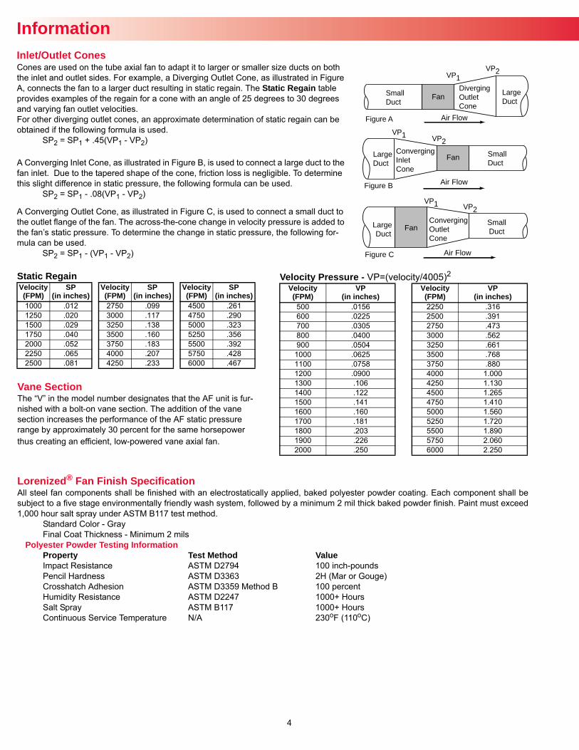
Cones are used on the tube axial fan to adapt it to larger or smaller size ducts on both the inlet and outlet sides. For example, a Diverging Outlet Cone, as illustrated in Figure A, connects the fan to a larger duct resulting in static regain. The Static Regain table provides examples of the regain for a cone with an angle of 25 degrees to 30 degrees and varying fan outlet velocities. For other diverging outlet cones, an approximate determination of static regain can be obtained if the following formula is used.
SP2 = SP1 + .45(VP1 - VP2) A Converging Inlet Cone, as illustrated in Figure B, is used to connect a large duct to the fan inlet. Due to the tapered shape of the cone, friction loss is negligible. To determine this slight difference in static pressure, the following formula can be used.
SP2 = SP1 - .08(VP1 - VP2)
A Converging Outlet Cone, as illustrated in Figure C, is used to connect a small duct to the outlet flange of the fan. The across-the-cone change in velocity pressure is added to the fan’s static pressure. To determine the change in static pressure, the following for-mula can be used.
SP2 = SP1 - (VP1 - VP2)
Figure B
Small Duct
Converging Inlet Cone
Large Duct
Air Flow
Fan
VP2
VP2
VP1
VP1
Figure C Air Flow
Converging Outlet Cone
Large Duct
FanSmallDuct
Figure A
Small Duct
Diverging Outlet Cone
Large Duct
Air Flow
Fan
VP1VP2
Inlet/Outlet Cones
Static Regain Velocity(FPM)
SP(in inches)
Velocity(FPM)
SP(in inches)
Velocity(FPM)
SP(in inches)
1000 .012 2750 .099 4500 .2611250 .020 3000 .117 4750 .2901500 .029 3250 .138 5000 .3231750 .040 3500 .160 5250 .3562000 .052 3750 .183 5500 .3922250 .065 4000 .207 5750 .4282500 .081 4250 .233 6000 .467
Velocity Pressure - VP=(velocity/4005)2 Velocity(FPM)
VP(in inches)
Velocity(FPM)
VP(in inches)
500 .0156 2250 .316600 .0225 2500 .391700 .0305 2750 .473800 .0400 3000 .562900 .0504 3250 .6611000 .0625 3500 .7681100 .0758 3750 .8801200 .0900 4000 1.0001300 .106 4250 1.1301400 .122 4500 1.2651500 .141 4750 1.4101600 .160 5000 1.5601700 .181 5250 1.7201800 .203 5500 1.8901900 .226 5750 2.0602000 .250 6000 2.250
Vane SectionThe “V” in the model number designates that the AF unit is fur-nished with a bolt-on vane section. The addition of the vane section increases the performance of the AF static pressure range by approximately 30 percent for the same horsepower thus creating an efficient, low-powered vane axial fan.
Lorenized® Fan Finish SpecificationAll steel fan components shall be finished with an electrostatically applied, baked polyester powder coating. Each component shall besubject to a five stage environmentally friendly wash system, followed by a minimum 2 mil thick baked powder finish. Paint must exceed1,000 hour salt spray under ASTM B117 test method.
Standard Color - GrayFinal Coat Thickness - Minimum 2 mils
Polyester Powder Testing InformationProperty Test Method ValueImpact Resistance ASTM D2794 100 inch-poundsPencil Hardness ASTM D3363 2H (Mar or Gouge)Crosshatch Adhesion ASTM D3359 Method B 100 percentHumidity Resistance ASTM D2247 1000+ HoursSalt Spray ASTM B117 1000+ HoursContinuous Service Temperature N/A 230oF (110oC)
5
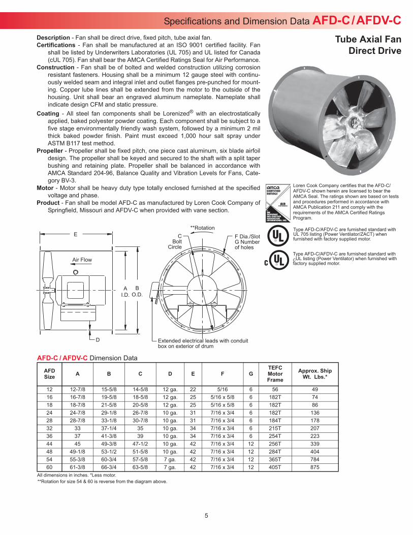
**RotationC
BoltCircle
F Dia./SlotG Numberof holes
AI.D.
BO.D.
Air Flow
Extended electrical leads with conduitbox on exterior of drum
D
E
Description - Fan shall be direct drive, fixed pitch, tube axial fan.Certifications - Fan shall be manufactured at an ISO 9001 certified facility. Fan
shall be listed by Underwriters Laboratories (UL 705) and UL listed for Canada(cUL 705). Fan shall bear the AMCA Certified Ratings Seal for Air Performance.
Construction - Fan shall be of bolted and welded construction utilizing corrosionresistant fasteners. Housing shall be a minimum 12 gauge steel with continu-ously welded seam and integral inlet and outlet flanges pre-punched for mount-ing. Copper lube lines shall be extended from the motor to the outside of thehousing. Unit shall bear an engraved aluminum nameplate. Nameplate shallindicate design CFM and static pressure.
Coating - All steel fan components shall be Lorenized® with an electrostaticallyapplied, baked polyester powder coating. Each component shall be subject to afive stage environmentally friendly wash system, followed by a minimum 2 milthick baked powder finish. Paint must exceed 1,000 hour salt spray underASTM B117 test method.
Propeller - Propeller shall be fixed pitch, one piece cast aluminum, six blade airfoildesign. The propeller shall be keyed and secured to the shaft with a split taperbushing and retaining plate. Propeller shall be balanced in accordance withAMCA Standard 204-96, Balance Quality and Vibration Levels for Fans, Cate-gory BV-3.
Motor - Motor shall be heavy duty type totally enclosed furnished at the specifiedvoltage and phase.
Product - Fan shall be model AFD-C as manufactured by Loren Cook Company ofSpringfield, Missouri and AFDV-C when provided with vane section.
Specifications and Dimension Data AFD-C/AFDV-CTube Axial Fan
Direct Drive
Type AFD-C/AFDV-C are furnished standard with UL 705 listing (Power Ventilator/ZACT) when furnished with factory supplied motor.
Type AFD-C/AFDV-C are furnished standard with CUL listing (Power Ventilator) when furnished with factory supplied motor.
Loren Cook Company certifies that the AFD-C/ AFDV-C shown herein are licensed to bear the AMCA Seal. The ratings shown are based on tests and procedures performed in accordance with AMCA Publication 211 and comply with the requirements of the AMCA Certified Ratings Program.
AFD-C / AFDV-C Dimension Data
All dimensions in inches. *Less motor.
AFDSize A B C D E F G
TEFCMotorFrame
Approx. ShipWt. Lbs.*
12 12-7/8 15-5/8 14-5/8 12 ga. 22 5/16 6 56 4916 16-7/8 19-5/8 18-5/8 12 ga. 25 5/16 x 5/8 6 182T 7418 18-7/8 21-5/8 20-5/8 12 ga. 25 5/16 x 5/8 6 182T 8624 24-7/8 29-1/8 26-7/8 10 ga. 31 7/16 x 3/4 6 182T 13628 28-7/8 33-1/8 30-7/8 10 ga. 31 7/16 x 3/4 6 184T 17832 33 37-1/4 35 10 ga. 34 7/16 x 3/4 6 215T 20736 37 41-3/8 39 10 ga. 34 7/16 x 3/4 6 254T 22344 45 49-3/8 47-1/2 10 ga. 42 7/16 x 3/4 12 256T 33948 49-1/8 53-1/2 51-5/8 10 ga. 42 7/16 x 3/4 12 284T 40454 55-3/8 60-3/4 57-5/8 7 ga. 42 7/16 x 3/4 12 365T 78460 61-3/8 66-3/4 63-5/8 7 ga. 42 7/16 x 3/4 12 405T 875
**Rotation for size 54 & 60 is reverse from the diagram above.
6
Type AFB-C/AFBV-C are furnished standard with UL 705 listing (Power Ventilator/ZACT) when furnished with factory supplied motor.
Type AFB-C/AFBV-C are furnished standard with CUL listing (Power Ventilator) when furnished with factory supplied motor.
Loren Cook Company certifies that the AFB-C/AFBV-C shown herein are licensed to bear the AMCA Seal. The ratings shown are based on tests and procedures performed in accordance with AMCA Publication 211 and comply with the requirements of the AMCA Certified Ratings Program.
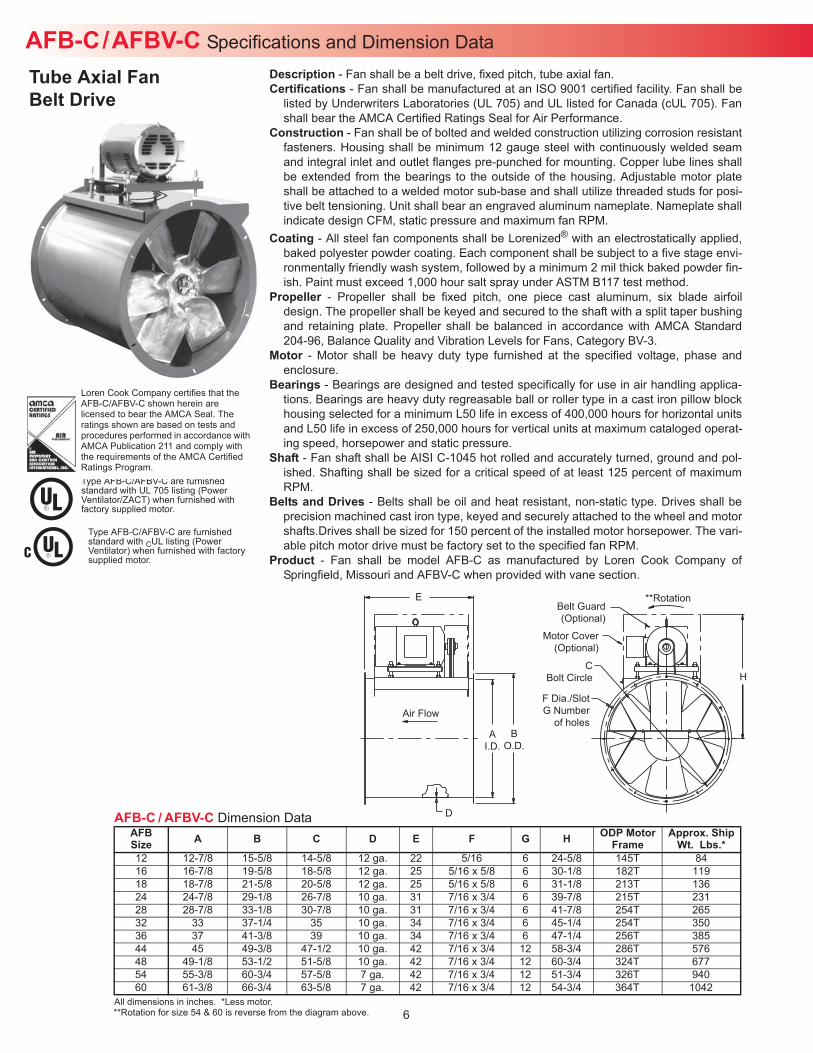
AFB-C/AFBV-C Specifications and Dimension DataDescription - Fan shall be a belt drive, fixed pitch, tube axial fan.Certifications - Fan shall be manufactured at an ISO 9001 certified facility. Fan shall be
listed by Underwriters Laboratories (UL 705) and UL listed for Canada (cUL 705). Fanshall bear the AMCA Certified Ratings Seal for Air Performance.
Construction - Fan shall be of bolted and welded construction utilizing corrosion resistantfasteners. Housing shall be minimum 12 gauge steel with continuously welded seamand integral inlet and outlet flanges pre-punched for mounting. Copper lube lines shallbe extended from the bearings to the outside of the housing. Adjustable motor plateshall be attached to a welded motor sub-base and shall utilize threaded studs for posi-tive belt tensioning. Unit shall bear an engraved aluminum nameplate. Nameplate shallindicate design CFM, static pressure and maximum fan RPM.
Coating - All steel fan components shall be Lorenized® with an electrostatically applied,baked polyester powder coating. Each component shall be subject to a five stage envi-ronmentally friendly wash system, followed by a minimum 2 mil thick baked powder fin-ish. Paint must exceed 1,000 hour salt spray under ASTM B117 test method.
Propeller - Propeller shall be fixed pitch, one piece cast aluminum, six blade airfoildesign. The propeller shall be keyed and secured to the shaft with a split taper bushingand retaining plate. Propeller shall be balanced in accordance with AMCA Standard204-96, Balance Quality and Vibration Levels for Fans, Category BV-3.
Motor - Motor shall be heavy duty type furnished at the specified voltage, phase andenclosure.
Bearings - Bearings are designed and tested specifically for use in air handling applica-tions. Bearings are heavy duty regreasable ball or roller type in a cast iron pillow blockhousing selected for a minimum L50 life in excess of 400,000 hours for horizontal unitsand L50 life in excess of 250,000 hours for vertical units at maximum cataloged operat-ing speed, horsepower and static pressure.
Shaft - Fan shaft shall be AISI C-1045 hot rolled and accurately turned, ground and pol-ished. Shafting shall be sized for a critical speed of at least 125 percent of maximumRPM.
Belts and Drives - Belts shall be oil and heat resistant, non-static type. Drives shall beprecision machined cast iron type, keyed and securely attached to the wheel and motorshafts.Drives shall be sized for 150 percent of the installed motor horsepower. The vari-able pitch motor drive must be factory set to the specified fan RPM.
Product - Fan shall be model AFB-C as manufactured by Loren Cook Company ofSpringfield, Missouri and AFBV-C when provided with vane section.
Tube Axial FanBelt Drive
AFB-C / AFBV-C Dimension Data
All dimensions in inches. *Less motor.
AFBSize A B C D E F G H ODP Motor
FrameApprox. Ship
Wt. Lbs.*12 12-7/8 15-5/8 14-5/8 12 ga. 22 5/16 6 24-5/8 145T 8416 16-7/8 19-5/8 18-5/8 12 ga. 25 5/16 x 5/8 6 30-1/8 182T 11918 18-7/8 21-5/8 20-5/8 12 ga. 25 5/16 x 5/8 6 31-1/8 213T 13624 24-7/8 29-1/8 26-7/8 10 ga. 31 7/16 x 3/4 6 39-7/8 215T 23128 28-7/8 33-1/8 30-7/8 10 ga. 31 7/16 x 3/4 6 41-7/8 254T 26532 33 37-1/4 35 10 ga. 34 7/16 x 3/4 6 45-1/4 254T 35036 37 41-3/8 39 10 ga. 34 7/16 x 3/4 6 47-1/4 256T 38544 45 49-3/8 47-1/2 10 ga. 42 7/16 x 3/4 12 58-3/4 286T 57648 49-1/8 53-1/2 51-5/8 10 ga. 42 7/16 x 3/4 12 60-3/4 324T 67754 55-3/8 60-3/4 57-5/8 7 ga. 42 7/16 x 3/4 12 51-3/4 326T 94060 61-3/8 66-3/4 63-5/8 7 ga. 42 7/16 x 3/4 12 54-3/4 364T 1042
E
D
**Rotation
Motor Cover(Optional)
CBolt Circle
F Dia./SlotG Number
of holesA
I.D.B
O.D.
Air Flow
Belt Guard(Optional)
H
**Rotation for size 54 & 60 is reverse from the diagram above.
7
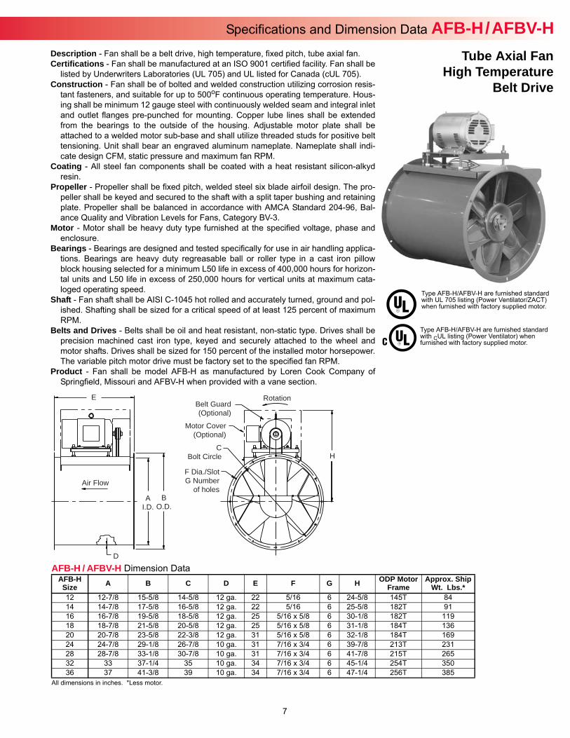
Specifications and Dimension Data AFB-H / AFBV-HDescription - Fan shall be a belt drive, high temperature, fixed pitch, tube axial fan.Certifications - Fan shall be manufactured at an ISO 9001 certified facility. Fan shall be
listed by Underwriters Laboratories (UL 705) and UL listed for Canada (cUL 705). Construction - Fan shall be of bolted and welded construction utilizing corrosion resis-
tant fasteners, and suitable for up to 500oF continuous operating temperature. Hous-ing shall be minimum 12 gauge steel with continuously welded seam and integral inletand outlet flanges pre-punched for mounting. Copper lube lines shall be extendedfrom the bearings to the outside of the housing. Adjustable motor plate shall beattached to a welded motor sub-base and shall utilize threaded studs for positive belttensioning. Unit shall bear an engraved aluminum nameplate. Nameplate shall indi-cate design CFM, static pressure and maximum fan RPM.
Coating - All steel fan components shall be coated with a heat resistant silicon-alkydresin.
Propeller - Propeller shall be fixed pitch, welded steel six blade airfoil design. The pro-peller shall be keyed and secured to the shaft with a split taper bushing and retainingplate. Propeller shall be balanced in accordance with AMCA Standard 204-96, Bal-ance Quality and Vibration Levels for Fans, Category BV-3.
Motor - Motor shall be heavy duty type furnished at the specified voltage, phase andenclosure.
Bearings - Bearings are designed and tested specifically for use in air handling applica-tions. Bearings are heavy duty regreasable ball or roller type in a cast iron pillowblock housing selected for a minimum L50 life in excess of 400,000 hours for horizon-tal units and L50 life in excess of 250,000 hours for vertical units at maximum cata-loged operating speed.
Shaft - Fan shaft shall be AISI C-1045 hot rolled and accurately turned, ground and pol-ished. Shafting shall be sized for a critical speed of at least 125 percent of maximumRPM.
Belts and Drives - Belts shall be oil and heat resistant, non-static type. Drives shall beprecision machined cast iron type, keyed and securely attached to the wheel andmotor shafts. Drives shall be sized for 150 percent of the installed motor horsepower.The variable pitch motor drive must be factory set to the specified fan RPM.
Product - Fan shall be model AFB-H as manufactured by Loren Cook Company ofSpringfield, Missouri and AFBV-H when provided with a vane section.
Tube Axial FanHigh Temperature
Belt Drive
Type AFB-H/AFBV-H are furnished standard with UL 705 listing (Power Ventilator/ZACT) when furnished with factory supplied motor.
Type AFB-H/AFBV-H are furnished standard with CUL listing (Power Ventilator) when furnished with factory supplied motor.
AFB-H / AFBV-H Dimension Data
All dimensions in inches. *Less motor.
AFB-HSize A B C D E F G H ODP Motor
FrameApprox. Ship
Wt. Lbs.*12 12-7/8 15-5/8 14-5/8 12 ga. 22 5/16 6 24-5/8 145T 8414 14-7/8 17-5/8 16-5/8 12 ga. 22 5/16 6 25-5/8 182T 9116 16-7/8 19-5/8 18-5/8 12 ga. 25 5/16 x 5/8 6 30-1/8 182T 11918 18-7/8 21-5/8 20-5/8 12 ga. 25 5/16 x 5/8 6 31-1/8 184T 13620 20-7/8 23-5/8 22-3/8 12 ga. 31 5/16 x 5/8 6 32-1/8 184T 16924 24-7/8 29-1/8 26-7/8 10 ga. 31 7/16 x 3/4 6 39-7/8 213T 23128 28-7/8 33-1/8 30-7/8 10 ga. 31 7/16 x 3/4 6 41-7/8 215T 26532 33 37-1/4 35 10 ga. 34 7/16 x 3/4 6 45-1/4 254T 35036 37 41-3/8 39 10 ga. 34 7/16 x 3/4 6 47-1/4 256T 385
E
D
Rotation
Motor Cover(Optional)
CBolt Circle
F Dia./SlotG Number
of holesA
I.D.B
O.D.
Air Flow
Belt Guard(Optional)
H
8
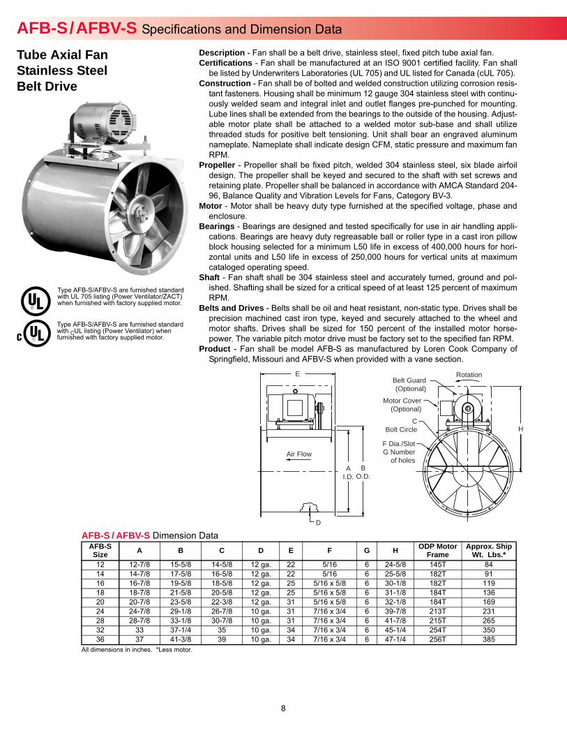
AFB-S / AFBV-S Specifications and Dimension Data
Type AFB-S/AFBV-S are furnished standard with UL 705 listing (Power Ventilator/ZACT) when furnished with factory supplied motor.
Type AFB-S/AFBV-S are furnished standard with CUL listing (Power Ventilator) when furnished with factory supplied motor.
Description - Fan shall be a belt drive, stainless steel, fixed pitch tube axial fan.Certifications - Fan shall be manufactured at an ISO 9001 certified facility. Fan shall
be listed by Underwriters Laboratories (UL 705) and UL listed for Canada (cUL 705). Construction - Fan shall be of bolted and welded construction utilizing corrosion resis-
tant fasteners. Housing shall be minimum 12 gauge 304 stainless steel with continu-ously welded seam and integral inlet and outlet flanges pre-punched for mounting.Lube lines shall be extended from the bearings to the outside of the housing. Adjust-able motor plate shall be attached to a welded motor sub-base and shall utilizethreaded studs for positive belt tensioning. Unit shall bear an engraved aluminumnameplate. Nameplate shall indicate design CFM, static pressure and maximum fanRPM.
Propeller - Propeller shall be fixed pitch, welded 304 stainless steel, six blade airfoildesign. The propeller shall be keyed and secured to the shaft with set screws andretaining plate. Propeller shall be balanced in accordance with AMCA Standard 204-96, Balance Quality and Vibration Levels for Fans, Category BV-3.
Motor - Motor shall be heavy duty type furnished at the specified voltage, phase andenclosure.
Bearings - Bearings are designed and tested specifically for use in air handling appli-cations. Bearings are heavy duty regreasable ball or roller type in a cast iron pillowblock housing selected for a minimum L50 life in excess of 400,000 hours for hori-zontal units and L50 life in excess of 250,000 hours for vertical units at maximumcataloged operating speed.
Shaft - Fan shaft shall be 304 stainless steel and accurately turned, ground and pol-ished. Shafting shall be sized for a critical speed of at least 125 percent of maximumRPM.
Belts and Drives - Belts shall be oil and heat resistant, non-static type. Drives shall beprecision machined cast iron type, keyed and securely attached to the wheel andmotor shafts. Drives shall be sized for 150 percent of the installed motor horse-power. The variable pitch motor drive must be factory set to the specified fan RPM.
Product - Fan shall be model AFB-S as manufactured by Loren Cook Company ofSpringfield, Missouri and AFBV-S when provided with a vane section.
Tube Axial FanStainless SteelBelt Drive
E
D
Rotation
Motor Cover(Optional)
CBolt Circle
F Dia./SlotG Number
of holesA
I.D.B
O.D.
Air Flow
Belt Guard(Optional)
H
AFB-S / AFBV-S Dimension Data
All dimensions in inches. *Less motor.
AFB-SSize A B C D E F G H ODP Motor
FrameApprox. Ship
Wt. Lbs.*12 12-7/8 15-5/8 14-5/8 12 ga. 22 5/16 6 24-5/8 145T 8414 14-7/8 17-5/8 16-5/8 12 ga. 22 5/16 6 25-5/8 182T 9116 16-7/8 19-5/8 18-5/8 12 ga. 25 5/16 x 5/8 6 30-1/8 182T 11918 18-7/8 21-5/8 20-5/8 12 ga. 25 5/16 x 5/8 6 31-1/8 184T 13620 20-7/8 23-5/8 22-3/8 12 ga. 31 5/16 x 5/8 6 32-1/8 184T 16924 24-7/8 29-1/8 26-7/8 10 ga. 31 7/16 x 3/4 6 39-7/8 213T 23128 28-7/8 33-1/8 30-7/8 10 ga. 31 7/16 x 3/4 6 41-7/8 215T 26532 33 37-1/4 35 10 ga. 34 7/16 x 3/4 6 45-1/4 254T 35036 37 41-3/8 39 10 ga. 34 7/16 x 3/4 6 47-1/4 256T 385
9
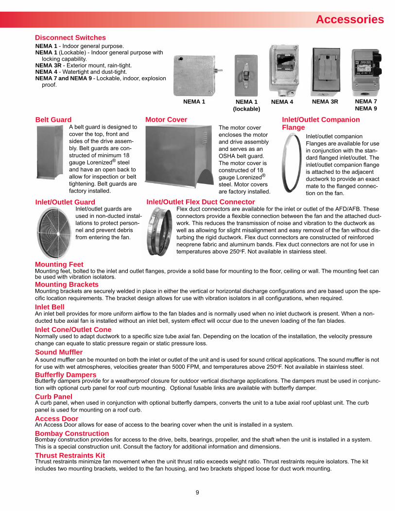
Accessories
Inlet/Outlet Guard
A belt guard is designed to cover the top, front and sides of the drive assem-bly. Belt guards are con-structed of minimum 18 gauge Lorenized® steel and have an open back to allow for inspection or belt tightening. Belt guards are factory installed.
The motor cover encloses the motor and drive assembly and serves as an OSHA belt guard. The motor cover is constructed of 18 gauge Lorenized® steel. Motor covers are factory installed.
Motor Cover Inlet/Outlet Companion Flange
Inlet/outlet companion Flanges are available for use in conjunction with the stan-dard flanged inlet/outlet. The inlet/outlet companion flange is attached to the adjacent ductwork to provide an exact mate to the flanged connec-tion on the fan.
Inlet/outlet guards are used in non-ducted instal-lations to protect person-nel and prevent debris from entering the fan.
Inlet/Outlet Flex Duct Connector
NEMA 1 - Indoor general purpose.NEMA 1 (Lockable) - Indoor general purpose with
locking capability.NEMA 3R - Exterior mount, rain-tight.NEMA 4 - Watertight and dust-tight.NEMA 7 and NEMA 9 - Lockable, indoor, explosion
proof.
Disconnect Switches
NEMA 1 NEMA 1(lockable)
NEMA 3RNEMA 4 NEMA 7NEMA 9
Belt Guard
Flex duct connectors are available for the inlet or outlet of the AFD/AFB. These connectors provide a flexible connection between the fan and the attached duct-work. This reduces the transmission of noise and vibration to the ductwork as well as allowing for slight misalignment and easy removal of the fan without dis-turbing the rigid ductwork. Flex duct connectors are constructed of reinforced neoprene fabric and aluminum bands. Flex duct connectors are not for use in temperatures above 250oF. Not available in stainless steel.
Mounting FeetMounting feet, bolted to the inlet and outlet flanges, provide a solid base for mounting to the floor, ceiling or wall. The mounting feet can be used with vibration isolators.Mounting BracketsMounting brackets are securely welded in place in either the vertical or horizontal discharge configurations and are based upon the spe-cific location requirements. The bracket design allows for use with vibration isolators in all configurations, when required.Inlet BellAn inlet bell provides for more uniform airflow to the fan blades and is normally used when no inlet ductwork is present. When a non-ducted tube axial fan is installed without an inlet bell, system effect will occur due to the uneven loading of the fan blades.Inlet Cone/Outlet ConeNormally used to adapt ductwork to a specific size tube axial fan. Depending on the location of the installation, the velocity pressure change can equate to static pressure regain or static pressure loss.Sound MufflerA sound muffler can be mounted on both the inlet or outlet of the unit and is used for sound critical applications. The sound muffler is not for use with wet atmospheres, velocities greater than 5000 FPM, and temperatures above 250oF. Not available in stainless steel.Bufferfly DampersButterfly dampers provide for a weatherproof closure for outdoor vertical discharge applications. The dampers must be used in conjunc-tion with optional curb panel for roof curb mounting. Optional fusable links are available with butterfly damper.Curb PanelA curb panel, when used in conjunction with optional butterfly dampers, converts the unit to a tube axial roof upblast unit. The curb panel is used for mounting on a roof curb. Access DoorAn Access Door allows for ease of access to the bearing cover when the unit is installed in a system.Bombay ConstructionBombay construction provides for access to the drive, belts, bearings, propeller, and the shaft when the unit is installed in a system. This is a special construction unit. Consult the factory for additional information and dimensions.Thrust Restraints KitThrust restraints minimize fan movement when the unit thrust ratio exceeds weight ratio. Thrust restraints require isolators. The kit includes two mounting brackets, welded to the fan housing, and two brackets shipped loose for duct work mounting.

10All dimensions in inches. Isolators listed are designed to provide a minimum of 50 percent of overload capacity.
Unit Rated Load(lbs.)
Spring. Rate(lbs./in.) A B C D E F Approx. Ship
Wt. Lbs.HF-120 120 98 6-1/8 5-5/8 5/16 2-1/8 3-1/2 3/8 2HF-220 220 196 6-1/8 5-5/8 5/16 2-1/8 3-1/2 3/8 2HF-320 320 302 6-1/8 5-5/8 5/16 2-1/8 3-1/2 3/8 2HF-370 370 366 6-1/8 5-5/8 5/16 2-1/8 3-1/2 3/8 2HF-500 500 500 6-1/8 5-5/8 5/16 2-1/8 3-1/2 3/8 2HF-700 700 700 6-1/8 5-5/8 5/16 2-1/8 3-1/2 3/8 2HF-800 800 588 9 7-1/2 7/16 3-1/2 5 5/8 13HF-1000 1000 826 9 7-1/2 7/16 3-1/2 5 5/8 13
Accessories
All dimensions in inches.
Unit Rated Load(lbs.) A B C D E F Approx. Ship
Wt. Lbs. RC-75 75 2-5/32 1-1/2 2-23/32 11/16 15/32 3/8 1RC-125 125 2-5/32 1-1/2 2-23/32 11/16 15/32 3/8 1RC-175 175 3-5/32 2-1/4 5-11/16 3/4 1-31/64 3/4 2RC-300 300 3-5/32 2-1/4 5-11/16 3/4 1-31/64 3/4 2RC-450 450 3-5/32 2-1/4 5-11/16 3/4 1-31/64 3/4 2RC-700 700 4 4-3/4 8 3/4 1-1/2 3/4 3RC-1100 1100 4 4-3/4 8 3/4 1-1/2 3/4 5
AB
E
D
Cslot
F boltdia.
C Oper. HeightE Free Height B
F
A
GD
D Dia. rodFDia.
EC
BA
Rubber-in-Shear Isolator - Ceiling Mounted
All dimensions in inches.
Unit Rated Load(lbs.) A B C D E F G Approx. Ship
Wt. Lbs. RF-55 55 1-13/16 3-3/16 1-7/64 5/16 NC 1-1/2 2-3/8 11/32 1
RF-120 120 2-3/8 3-7/8 1-1/4 3/8 NC 1-3/4 3 11/32 1RF-220 220 2-3/8 3-7/8 1-1/4 3/8 NC 1-3/4 3 11/32 1RF-375 375 2-3/8 3-7/8 1-1/4 3/8 NC 1-3/4 3 11/32 1RF-600 600 3-1/4 5-1/2 2 1/2 NC 2-1/2 4-1/8 9/16 2RF-1100 1100 3-1/4 5-1/2 2 1/2 NC 2-1/2 4-1/8 9/16 2
Rubber-in-Shear Isolator - Floor Mounted
Housed Spring Isolator - Floor Mounted
AB
Choledia.
Fboltdia.E
D
All dimensions in inches.
Unit Rated Load(lbs.)
Spring. Rate(lbs./in.) A B C D Approx. Ship Wt.
Lbs.SC-35 35 23 3-11/16 2-1/4 5-1/4 1/2 2SC-70 70 51 3-11/16 2-1/4 5-1/4 1/2 2
SC-125 125 100 3-11/16 2-1/4 5-1/4 1/2 2SC-245 245 206 3-11/16 2-1/4 5-1/4 1/2 2SC-370 370 370 3-11/16 2-1/4 5-1/4 1/2 2SC-500 500 500 3-11/16 2-1/4 5-1/4 5/8 2
SC-1000 1000 870 5-9/16 3-5/8 8-9/16 3/4 5
All dimensions in inches. Isolators listed are designed to provide a minimum of 50 percent of overload capacity. A single hole is provided at the center of the plate.
Unit Rated Load(lbs.)
Spring. Rate(lbs./in.) A B C D E F Approx. Ship Wt.
Lbs.SF-70 70 51 2-5/8 ** 11/16 2-5/8 3-1/2 3/8 2
SF-120 120 98 4-1/2 3-1/2 9/16 2-1/2 3-1/2 3/8 2SF-220 220 196 4-1/2 3-1/2 9/16 2-1/2 3-1/2 3/8 2SF-370 370 366 4-1/2 3-1/2 9/16 2-1/2 3-1/2 3/8 2SF-625 625 419 7 5-1/2 11/16 4 4-1/2 3/8 4
SF-1250 1250 1096 7 5-1/2 11/16 4 4-3/4 3/8 5
Spring Isolator - Ceiling Mounted
Free Standing Spring Isolator - Floor Mounted
AB
D
E
Fboltdia.
Choledia.
All dimensions in inches. Isolators listed are designed to provide a minimum of 50 percent of overload.
Unit Rated Load(lbs.)
Spring. Rate(lbs./in.) A B C D E F Approx. Ship
Wt. Lbs.RS-70 70 51 4-3/4 3-3/4 7/16 3 5 1/2 3RS-120 120 98 4-3/4 3-3/4 7/16 3 5 1/2 3RS-220 220 196 4-3/4 3-3/4 7/16 3 5 1/2 3RS-370 370 366 4-3/4 3-3/4 7/16 3 5 1/2 3RS-625 625 419 8 6-1/2 11/16 4 7-1/2 5/8 6RS-1250 1250 1096 8 6-1/2 11/16 4 7-1/2 5/8 7
Restrained Spring Isolator - Floor Mounted
AB
C
D Dia. rod

11
Data AFD-C / AFDV-CAFD-C
Performance shown is for installation type D: ducted inlet, ducted outlet. Performance ratings do not include the effects of appurtenances in the airstream.
Unit MaxBHP RPM Mtr.
HPCFM vs. Static Pressure
0.000” SP 0.500” SP 1.000” SP 1.500” SP 2.000” SP 2.500” SP 3.000” SP 3.500” SP 4.000” SP 4.500” SP 5.000” SP12AF17D-C 0.10 1725 1/4 1154 22312AF34D-C 0.57 3450 1/2 2308 2035 171616AF17D-C 0.50 1725 1/2 2875 2392 121116AF34D-C 3.28 3450 3 5750 5523 5290 5047 4783 448118AF11D-C 0.20 1140 1/4 2656 82018AF17D-C 0.81 1725 3/4 4019 3345 1497 82924AF08D-C 0.35 860 1/3 4459 143824AF11D-C 0.89 1140 1 5911 4515 158628AF08D-C 0.96 860 1 7155 3852 139328AF11D-C 2.06 1140 2 9484 7990 4386 255032AF08D-C 2.20 860 2 10663 8184 3445 126532AF11D-C 5.02 1160 5 14383 12671 10537 5776 4043 229836AF08D-C 3.10 870 3 15041 12492 6428 348536AF11D-C 8.04 1160 7-1/2 20055 18345 16109 10746 7495 5269 353944AF05D-C 1.67 575 2 17969 1217444AF06D-C 4.49 690 5 21562 17747 9370 541244AF08D-C 7.86 870 7-1/2 27187 24494 20574 12440 905444AF11D-C 14.96 1170 15 36562 34712 32475 29719 25856 1811448AF06D-C 4.63 690 5 27876 23920 1438148AF08D-C 10.37 850 10 34341 31402 27347 18005 1344948AF11D-C 25.60 1170 25 47269 45282 42961 40186 36890 31170 23105 2006054AF06D-C 9.23 690 10 39488 35284 28942 1712754AF08D-C 21.57 870 20 49789 46685 42747 37640 25775 20647 1653054AF11D-C 42.17 1160 40 66386 64166 61633 58788 55466 51638 45913 35142 3032260AF06D-C 25.35 690 25 53945 49451 43300 29279 21648 15997 11516 731260AF08D-C 42.36 870 40 68018 64647 60587 55603 49008 34506 28914 24354 19661 16344
AFDV-C
Unit MaxBHP RPM Mtr.
HPCFM vs. Static Pressure
0.000” SP 0.500” SP 1.000” SP 1.500” SP 2.000” SP 2.500” SP 3.000” SP 3.500” SP 4.000” SP 4.500” SP 5.000” SP12AF17DV-C 0.09 1725 1/4 1157 33712AF34DV-C 0.52 3450 1/2 2313 2058 176316AF17DV-C 0.42 1725 1/2 2836 2353 130116AF34DV-C 3.30 3450 3 5671 5420 5187 4956 4705 4421 4095 364118AF11DV-C 0.19 1140 1/4 2619 113618AF17DV-C 0.79 1725 3/4 3963 3390 2072 109924AF08DV-C 0.31 860 1/3 4427 195424AF11DV-C 0.81 1140 1 5869 4621 210028AF08DV-C 0.92 860 1 7052 5188 182328AF11DV-C 1.86 1140 2 9348 8101 6327 314332AF08DV-C 2.12 860 2 10557 8489 3896 166832AF11DV-C 4.76 1160 5 14240 12775 11112 8367 4421 285936AF08DV-C 2.96 870 3 14941 12693 9596 439836AF11DV-C 7.77 1160 7-1/2 19922 18353 16511 14400 10224 6559 474044AF05DV-C 1.65 575 2 17981 1354244AF06DV-C 5.48 690 5 21577 18277 12361 6075 294844AF08DV-C 7.14 870 7-1/2 27206 24758 21625 17023 1031744AF11DV-C 15.59 1170 15 36588 34836 32909 30690 27978 24657 1934048AF06DV-C 5.48 690 5 27896 24412 19233 1050248AF08DV-C 9.38 850 10 34365 31664 28373 23880 1604148AF11DV-C 25.24 1170 25 47302 45407 43359 41098 38461 35335 31605 25856 1998054AF06DV-C 10.26 690 10 39516 35715 30722 22554 1362354AF08DV-C 19.59 870 20 49824 46915 43621 39575 34414 25979 1883354AF11DV-C 41.87 1160 40 66432 64299 62037 59607 56940 53884 50376 46371 41455 3378460AF06DV-C 26.82 690 25 53983 49844 44842 38076 26368 18154 12882 8764 508960AF08DV-C 43.59 870 40 68066 64869 61362 57346 52462 46513 37330 27928 22649 18306 14617
12
FLOW (CFM)
STAT
IC P
RES
SUR
E (In
W.G
.)
0 600 1200 1800 2400 3000
5.00
4.00
3.00
2.00
1.00
0
3997 RPM M
ax
.5 HP 319 RPM
.75 HP
3600 RPM
1 HP
3200 RPM 1.5 HP
2800 RPM 2 HP
2400 RPM 2000 RPM 1500 RPM 1100 RPM
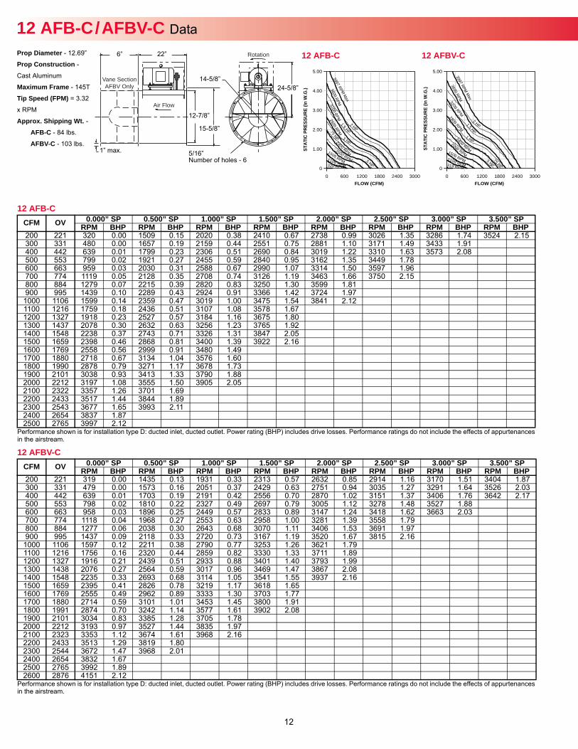
12 AFBV-CProp Diameter - 12.69”
Prop Construction -
Cast Aluminum
Maximum Frame - 145T
Tip Speed (FPM) = 3.32
x RPM
Approx. Shipping Wt. -AFB-C - 84 lbs.
AFBV-C - 103 lbs.
Rotation
Air Flow
Vane SectionAFBV Only
12 AFB-C
Performance shown is for installation type D: ducted inlet, ducted outlet. Power rating (BHP) includes drive losses. Performance ratings do not include the effects of appurtenances in the airstream.
CFM OV 0.000” SP 0.500” SP 1.000” SP 1.500” SP 2.000” SP 2.500” SP 3.000” SP 3.500” SPRPM BHP RPM BHP RPM BHP RPM BHP RPM BHP RPM BHP RPM BHP RPM BHP
200 221 320 0.00 1509 0.15 2020 0.38 2410 0.67 2738 0.99 3026 1.35 3286 1.74 3524 2.15300 331 480 0.00 1657 0.19 2159 0.44 2551 0.75 2881 1.10 3171 1.49 3433 1.91400 442 639 0.01 1799 0.23 2306 0.51 2690 0.84 3019 1.22 3310 1.63 3573 2.08500 553 799 0.02 1921 0.27 2455 0.59 2840 0.95 3162 1.35 3449 1.78600 663 959 0.03 2030 0.31 2588 0.67 2990 1.07 3314 1.50 3597 1.96700 774 1119 0.05 2128 0.35 2708 0.74 3126 1.19 3463 1.66 3750 2.15800 884 1279 0.07 2215 0.39 2820 0.83 3250 1.30 3599 1.81900 995 1439 0.10 2289 0.43 2924 0.91 3366 1.42 3724 1.971000 1106 1599 0.14 2359 0.47 3019 1.00 3475 1.54 3841 2.121100 1216 1759 0.18 2436 0.51 3107 1.08 3578 1.671200 1327 1918 0.23 2527 0.57 3184 1.16 3675 1.801300 1437 2078 0.30 2632 0.63 3256 1.23 3765 1.921400 1548 2238 0.37 2743 0.71 3326 1.31 3847 2.051500 1659 2398 0.46 2868 0.81 3400 1.39 3922 2.161600 1769 2558 0.56 2999 0.91 3480 1.491700 1880 2718 0.67 3134 1.04 3576 1.601800 1990 2878 0.79 3271 1.17 3678 1.731900 2101 3038 0.93 3413 1.33 3790 1.882000 2212 3197 1.08 3555 1.50 3905 2.052100 2322 3357 1.26 3701 1.692200 2433 3517 1.44 3844 1.892300 2543 3677 1.65 3993 2.112400 2654 3837 1.872500 2765 3997 2.12
FLOW (CFM)
STAT
IC P
RES
SUR
E (In
W.G
.)
0 600 1200 1800 2400 3000
5.00
4.00
3.00
2.00
1.00
0
Mx
3997 RPMa
.5 HP 320 RPM
.75 HP 3600 RPM
1 HP
3200 RPM 1.5 HP
2800 RPM
2 HP
2400 RPM 2000 RPM
1500 RPM 1100 RPM
12 AFB-C / AFBV-C Data 22”
12-7/8”
15-5/8”
14-5/8”24-5/8”
6”
1” max.
12 AFBV-C
Performance shown is for installation type D: ducted inlet, ducted outlet. Power rating (BHP) includes drive losses. Performance ratings do not include the effects of appurtenances in the airstream.
CFM OV 0.000” SP 0.500” SP 1.000” SP 1.500” SP 2.000” SP 2.500” SP 3.000” SP 3.500” SPRPM BHP RPM BHP RPM BHP RPM BHP RPM BHP RPM BHP RPM BHP RPM BHP
200 221 319 0.00 1435 0.13 1931 0.33 2313 0.57 2632 0.85 2914 1.16 3170 1.51 3404 1.87300 331 479 0.00 1573 0.16 2051 0.37 2429 0.63 2751 0.94 3035 1.27 3291 1.64 3526 2.03400 442 639 0.01 1703 0.19 2191 0.42 2556 0.70 2870 1.02 3151 1.37 3406 1.76 3642 2.17500 553 798 0.02 1810 0.22 2327 0.49 2697 0.79 3005 1.12 3278 1.48 3527 1.88600 663 958 0.03 1896 0.25 2449 0.57 2833 0.89 3147 1.24 3418 1.62 3663 2.03700 774 1118 0.04 1968 0.27 2553 0.63 2958 1.00 3281 1.39 3558 1.79800 884 1277 0.06 2038 0.30 2643 0.68 3070 1.11 3406 1.53 3691 1.97900 995 1437 0.09 2118 0.33 2720 0.73 3167 1.19 3520 1.67 3815 2.16
1000 1106 1597 0.12 2211 0.38 2790 0.77 3253 1.26 3621 1.791100 1216 1756 0.16 2320 0.44 2859 0.82 3330 1.33 3711 1.891200 1327 1916 0.21 2439 0.51 2933 0.88 3401 1.40 3793 1.991300 1438 2076 0.27 2564 0.59 3017 0.96 3469 1.47 3867 2.081400 1548 2235 0.33 2693 0.68 3114 1.05 3541 1.55 3937 2.161500 1659 2395 0.41 2826 0.78 3219 1.17 3618 1.651600 1769 2555 0.49 2962 0.89 3333 1.30 3703 1.771700 1880 2714 0.59 3101 1.01 3453 1.45 3800 1.911800 1991 2874 0.70 3242 1.14 3577 1.61 3902 2.081900 2101 3034 0.83 3385 1.28 3705 1.782000 2212 3193 0.97 3527 1.44 3835 1.972100 2323 3353 1.12 3674 1.61 3968 2.162200 2433 3513 1.29 3819 1.802300 2544 3672 1.47 3968 2.012400 2654 3832 1.672500 2765 3992 1.892600 2876 4151 2.12
12 AFB-C
5/16” Number of holes - 6
13
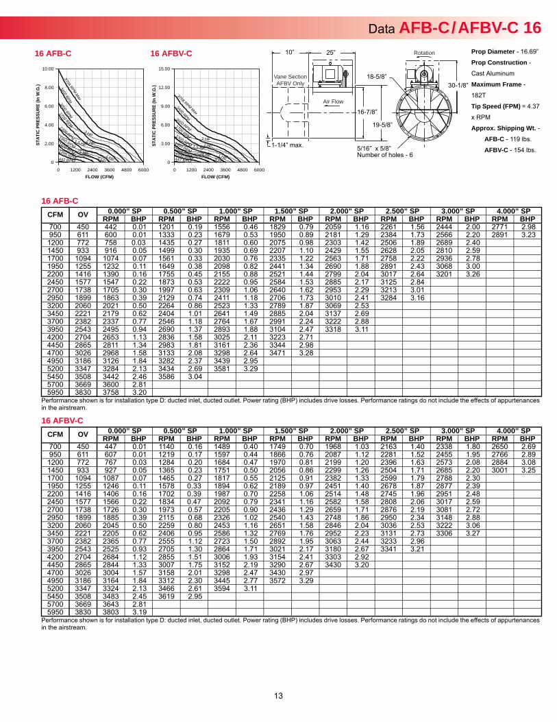
Data AFB-C / AFBV-C 16Prop Diameter - 16.69”
Prop Construction -
Cast Aluminum
Maximum Frame -
182T
Tip Speed (FPM) = 4.37
x RPM
Approx. Shipping Wt. -AFB-C - 119 lbs.
AFBV-C - 154 lbs.
Rotation
Air Flow
Vane SectionAFBV Only
25”
16-7/8”
19-5/8”
18-5/8”30-1/8”
5/16” x 5/8”Number of holes - 6
10”
1-1/4” max.
16 AFBV-C
Performance shown is for installation type D: ducted inlet, ducted outlet. Power rating (BHP) includes drive losses. Performance ratings do not include the effects of appurtenances in the airstream.
CFM OV 0.000” SP 0.500” SP 1.000” SP 1.500” SP 2.000” SP 2.500” SP 3.000” SP 4.000” SPRPM BHP RPM BHP RPM BHP RPM BHP RPM BHP RPM BHP RPM BHP RPM BHP
700 450 447 0.01 1140 0.16 1489 0.40 1749 0.70 1968 1.03 2163 1.40 2338 1.80 2650 2.69950 611 607 0.01 1219 0.17 1597 0.44 1866 0.76 2087 1.12 2281 1.52 2455 1.95 2766 2.89
1200 772 767 0.03 1284 0.20 1684 0.47 1970 0.81 2199 1.20 2396 1.63 2573 2.08 2884 3.081450 933 927 0.05 1365 0.23 1751 0.50 2056 0.86 2299 1.26 2504 1.71 2685 2.20 3001 3.251700 1094 1087 0.07 1465 0.27 1817 0.55 2125 0.91 2382 1.33 2599 1.79 2788 2.301950 1255 1246 0.11 1578 0.33 1894 0.62 2189 0.97 2451 1.40 2678 1.87 2877 2.392200 1416 1406 0.16 1702 0.39 1987 0.70 2258 1.06 2514 1.48 2745 1.96 2951 2.482450 1577 1566 0.22 1834 0.47 2092 0.79 2341 1.16 2582 1.58 2808 2.06 3017 2.592700 1738 1726 0.30 1973 0.57 2205 0.90 2436 1.29 2659 1.71 2876 2.19 3081 2.722950 1899 1885 0.39 2115 0.68 2326 1.02 2540 1.43 2748 1.86 2950 2.34 3148 2.883200 2060 2045 0.50 2259 0.80 2453 1.16 2651 1.58 2846 2.04 3036 2.53 3222 3.063450 2221 2205 0.62 2406 0.95 2586 1.32 2769 1.76 2952 2.23 3131 2.73 3306 3.273700 2382 2365 0.77 2555 1.12 2723 1.50 2892 1.95 3063 2.44 3233 2.963950 2543 2525 0.93 2705 1.30 2864 1.71 3021 2.17 3180 2.67 3341 3.214200 2704 2684 1.12 2855 1.51 3006 1.93 3154 2.41 3303 2.924450 2865 2844 1.33 3007 1.75 3152 2.19 3290 2.67 3430 3.204700 3026 3004 1.57 3158 2.01 3298 2.47 3430 2.974950 3186 3164 1.84 3312 2.30 3445 2.77 3572 3.295200 3347 3324 2.13 3466 2.61 3594 3.115450 3508 3483 2.45 3619 2.955700 3669 3643 2.815950 3830 3803 3.19
FLOW (CFM)
STAT
IC P
RES
SUR
E (In
W.G
.)
0 1200 2400 3600 4800 6000
15.00
12.00
9.00
6.00
3.00
0
3758 RPM Max
.5 HP 447 RPM
.75 HP
3400 RPM
1 HP
3000 RPM
1.5 HP
2700 RPM
2 HP
2300 RPM 3 HP
1900 RPM 1600 RPM 1200 RPM
16 AFBV-C
FLOW (CFM)
STAT
IC P
RES
SUR
E (In
W.G
.)
0 1200 2400 3600 4800 6000
10.00
8.00
6.00
4.00
2.00
0
3758 RPM Max
.5 HP 442 RPM
.75 HP
3400 RPM
1 HP
3000 RPM
1.5 HP
2700 RPM
2 HP
2300 RPM 3 HP 1900 RPM
1600 RPM 1200 RPM
16 AFB-C
16 AFB-C
Performance shown is for installation type D: ducted inlet, ducted outlet. Power rating (BHP) includes drive losses. Performance ratings do not include the effects of appurtenances in the airstream.
CFM OV 0.000” SP 0.500” SP 1.000” SP 1.500” SP 2.000” SP 2.500” SP 3.000” SP 4.000” SPRPM BHP RPM BHP RPM BHP RPM BHP RPM BHP RPM BHP RPM BHP RPM BHP
700 450 442 0.01 1201 0.19 1556 0.46 1829 0.79 2059 1.16 2261 1.56 2444 2.00 2771 2.98950 611 600 0.01 1333 0.23 1679 0.53 1950 0.89 2181 1.29 2384 1.73 2566 2.20 2891 3.231200 772 758 0.03 1435 0.27 1811 0.60 2075 0.98 2303 1.42 2506 1.89 2689 2.401450 933 916 0.05 1499 0.30 1935 0.69 2207 1.10 2429 1.55 2628 2.05 2810 2.591700 1094 1074 0.07 1561 0.33 2030 0.76 2335 1.22 2563 1.71 2758 2.22 2936 2.781950 1255 1232 0.11 1649 0.38 2098 0.82 2441 1.34 2690 1.88 2891 2.43 3068 3.002200 1416 1390 0.16 1755 0.45 2155 0.88 2521 1.44 2799 2.04 3017 2.64 3201 3.262450 1577 1547 0.22 1873 0.53 2222 0.95 2584 1.53 2885 2.17 3125 2.842700 1738 1705 0.30 1997 0.63 2309 1.06 2640 1.62 2953 2.29 3213 3.012950 1899 1863 0.39 2129 0.74 2411 1.18 2706 1.73 3010 2.41 3284 3.163200 2060 2021 0.50 2264 0.86 2523 1.33 2789 1.87 3069 2.533450 2221 2179 0.62 2404 1.01 2641 1.49 2885 2.04 3137 2.693700 2382 2337 0.77 2546 1.18 2764 1.67 2991 2.24 3222 2.883950 2543 2495 0.94 2690 1.37 2893 1.88 3104 2.47 3318 3.114200 2704 2653 1.13 2836 1.58 3025 2.11 3223 2.714450 2865 2811 1.34 2983 1.81 3161 2.36 3344 2.984700 3026 2968 1.58 3133 2.08 3298 2.64 3471 3.284950 3186 3126 1.84 3282 2.37 3439 2.955200 3347 3284 2.13 3434 2.69 3581 3.295450 3508 3442 2.46 3586 3.045700 3669 3600 2.815950 3830 3758 3.20
14
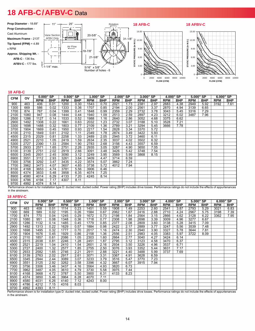
18 AFB-C / AFBV-C Data Prop Diameter - 18.69”
Prop Construction -
Cast Aluminum
Maximum Frame - 213T
Tip Speed (FPM) = 4.89
x RPM
Approx. Shipping Wt. -AFB-C - 136 lbs.
AFBV-C - 177 lbs.
Rotation
Air Flow
Vane SectionAFBV Only
25”
18-7/8”
21-5/8”
20-5/8”31-1/8”
11”
1-1/4” max.
18 AFB-C
Performance shown is for installation type D: ducted inlet, ducted outlet. Power rating (BHP) includes drive losses. Performance ratings do not include the effects of appurtenances in the airstream.
CFM OV 0.000” SP 0.500” SP 1.000” SP 2.000” SP 3.000” SP 4.000” SP 5.000” SP 6.000” SPRPM BHP RPM BHP RPM BHP RPM BHP RPM BHP RPM BHP RPM BHP RPM BHP
900 463 406 0.01 1200 0.30 1543 0.70 2021 1.73 2381 2.97 2683 4.38 2949 5.92 3192 7.611300 669 586 0.02 1333 0.36 1707 0.85 2194 2.00 2561 3.37 2870 4.94 3139 6.651700 874 767 0.04 1399 0.41 1848 0.99 2359 2.29 2732 3.78 3043 5.45 3316 7.292100 1080 947 0.08 1444 0.44 1940 1.09 2513 2.59 2897 4.23 3212 6.02 3487 7.962500 1286 1127 0.14 1533 0.52 1988 1.16 2640 2.86 3052 4.68 3375 6.622900 1492 1308 0.22 1661 0.63 2032 1.23 2732 3.07 3188 5.10 3528 7.213300 1698 1488 0.32 1803 0.77 2109 1.36 2789 3.21 3294 5.45 3666 7.783700 1904 1669 0.45 1950 0.93 2217 1.54 2828 3.34 3370 5.724100 2110 1849 0.61 2102 1.11 2349 1.78 2874 3.49 3422 5.934500 2315 2029 0.81 2258 1.33 2489 2.05 2945 3.72 3460 6.114900 2521 2210 1.05 2419 1.59 2634 2.35 3037 4.02 3502 6.325300 2727 2390 1.33 2584 1.90 2783 2.68 3156 4.43 3557 6.595700 2933 2571 1.65 2751 2.26 2935 3.05 3287 4.90 3650 7.056100 3139 2751 2.02 2919 2.66 3091 3.48 3426 5.42 3748 7.546500 3345 2931 2.45 3090 3.12 3249 3.95 3569 5.99 3868 8.156900 3551 3112 2.93 3261 3.64 3409 4.47 3714 6.597300 3756 3292 3.47 3435 4.22 3574 5.07 3862 7.247700 3962 3473 4.07 3607 4.85 3738 5.72 4012 7.948100 4168 3653 4.74 3781 5.56 3906 6.468500 4374 3833 5.48 3958 6.35 4074 7.258900 4580 4014 6.29 4133 7.20 4245 8.149300 4786 4194 7.17 4307 8.119700 4992 4374 8.14
18 AFBV-C
Performance shown is for installation type D: ducted inlet, ducted outlet. Power rating (BHP) includes drive losses. Performance ratings do not include the effects of appurtenances in the airstream.
CFM OV 0.000” SP 0.500” SP 1.000” SP 2.000” SP 3.000” SP 4.000” SP 5.000” SP 6.000” SPRPM BHP RPM BHP RPM BHP RPM BHP RPM BHP RPM BHP RPM BHP RPM BHP
900 463 408 0.01 1114 0.23 1451 0.59 1908 1.49 2253 2.60 2541 3.87 2793 5.29 3021 6.831300 669 589 0.02 1195 0.26 1584 0.67 2062 1.67 2416 2.88 2710 4.24 2967 5.75 3198 7.391700 874 770 0.04 1245 0.29 1672 0.73 2198 1.84 2564 3.15 2866 4.62 3128 6.22 3362 7.952100 1080 951 0.08 1348 0.36 1718 0.77 2308 1.98 2698 3.39 3009 4.96 3277 6.672500 1286 1132 0.14 1485 0.45 1779 0.85 2377 2.08 2809 3.60 3138 5.28 3415 7.092900 1492 1313 0.22 1629 0.57 1884 0.98 2422 2.17 2889 3.77 3247 5.56 3539 7.483300 1698 1495 0.32 1777 0.70 2017 1.16 2474 2.30 2940 3.90 3327 5.78 3644 7.813700 1904 1676 0.45 1929 0.86 2158 1.36 2556 2.51 2983 4.05 3383 5.97 3722 8.094100 2110 1857 0.61 2086 1.05 2303 1.60 2664 2.77 3040 4.27 3424 6.144500 2315 2038 0.81 2246 1.28 2451 1.87 2795 3.12 3123 4.58 3470 6.374900 2521 2219 1.04 2410 1.54 2601 2.16 2934 3.50 3226 4.96 3537 6.715300 2727 2400 1.32 2577 1.85 2755 2.50 3076 3.93 3352 5.44 3631 7.175700 2933 2582 1.65 2746 2.21 2911 2.88 3221 4.40 3488 5.99 3737 7.696100 3139 2763 2.02 2917 2.61 3071 3.31 3367 4.91 3628 6.596500 3345 2944 2.44 3089 3.07 3233 3.79 3516 5.47 3770 7.236900 3551 3125 2.92 3262 3.58 3396 4.32 3667 6.07 3915 7.947300 3756 3306 3.46 3437 4.16 3564 4.93 3820 6.737700 3962 3487 4.05 3610 4.79 3730 5.58 3975 7.448100 4168 3668 4.72 3787 5.50 3900 6.31 4133 8.238500 4374 3850 5.46 3964 6.28 4070 7.118900 4580 4031 6.26 4140 7.12 4243 8.009300 4786 4212 7.15 4316 8.039700 4992 4393 8.11
5/16” x 5/8”Number of holes - 6
FLOW (CFM)
STAT
IC P
RES
SUR
E (In
W.G
.)
0 2000 4000 6000 8000 10000
15.00
12.00
9.00
6.00
3.00
0
4374 RPM M
ax
408 RPM
3900 RPM 3500 RPM
1 HP
3100 RPM
1.5 HP
2600 RPM
2 HP
2200 RPM 3 HP 1700 RPM
5 HP
1300 RPM
7.5 HP
18 AFBV-C
FLOW (CFM)
STAT
IC P
RES
SUR
E (In
W.G
.)
0 2000 4000 6000 8000 10000
15.00
12.00
9.00
6.00
3.00
0
4374 RPM M
ax
406 RPM
3900 RPM 3500 RPM
1 HP
3100 RPM
1.5 HP
2600 RPM 2 HP
2200 RPM 3 HP 1700 RPM
5 HP
1300 RPM
7.5 HP
18 AFB-C
15
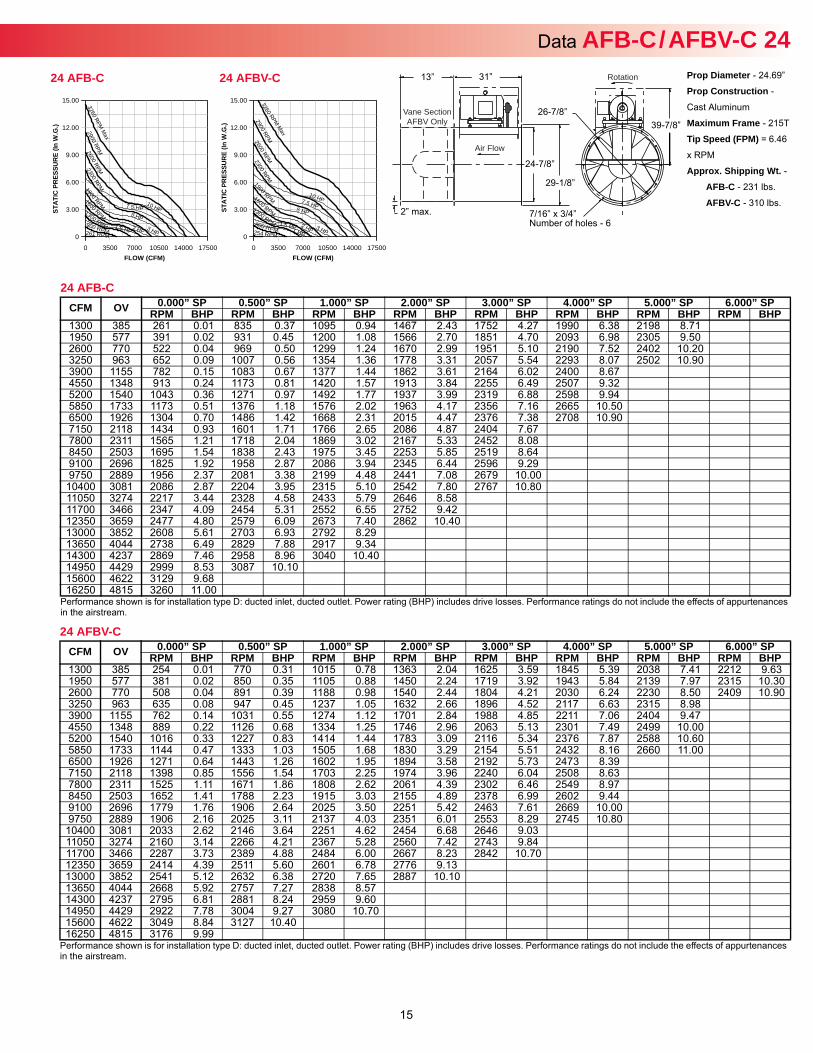
Data AFB-C / AFBV-C 24Prop Diameter - 24.69”
Prop Construction -
Cast Aluminum
Maximum Frame - 215T
Tip Speed (FPM) = 6.46
x RPM
Approx. Shipping Wt. -AFB-C - 231 lbs.
AFBV-C - 310 lbs.
Rotation
Air Flow
Vane SectionAFBV Only
31”
24-7/8”
29-1/8”
26-7/8”39-7/8”
7/16” x 3/4” Number of holes - 6
13”
2” max.
24 AFB-C
Performance shown is for installation type D: ducted inlet, ducted outlet. Power rating (BHP) includes drive losses. Performance ratings do not include the effects of appurtenances in the airstream.
CFM OV 0.000” SP 0.500” SP 1.000” SP 2.000” SP 3.000” SP 4.000” SP 5.000” SP 6.000” SPRPM BHP RPM BHP RPM BHP RPM BHP RPM BHP RPM BHP RPM BHP RPM BHP
1300 385 261 0.01 835 0.37 1095 0.94 1467 2.43 1752 4.27 1990 6.38 2198 8.711950 577 391 0.02 931 0.45 1200 1.08 1566 2.70 1851 4.70 2093 6.98 2305 9.502600 770 522 0.04 969 0.50 1299 1.24 1670 2.99 1951 5.10 2190 7.52 2402 10.203250 963 652 0.09 1007 0.56 1354 1.36 1778 3.31 2057 5.54 2293 8.07 2502 10.903900 1155 782 0.15 1083 0.67 1377 1.44 1862 3.61 2164 6.02 2400 8.674550 1348 913 0.24 1173 0.81 1420 1.57 1913 3.84 2255 6.49 2507 9.325200 1540 1043 0.36 1271 0.97 1492 1.77 1937 3.99 2319 6.88 2598 9.945850 1733 1173 0.51 1376 1.18 1576 2.02 1963 4.17 2356 7.16 2665 10.506500 1926 1304 0.70 1486 1.42 1668 2.31 2015 4.47 2376 7.38 2708 10.907150 2118 1434 0.93 1601 1.71 1766 2.65 2086 4.87 2404 7.677800 2311 1565 1.21 1718 2.04 1869 3.02 2167 5.33 2452 8.088450 2503 1695 1.54 1838 2.43 1975 3.45 2253 5.85 2519 8.649100 2696 1825 1.92 1958 2.87 2086 3.94 2345 6.44 2596 9.299750 2889 1956 2.37 2081 3.38 2199 4.48 2441 7.08 2679 10.00
10400 3081 2086 2.87 2204 3.95 2315 5.10 2542 7.80 2767 10.8011050 3274 2217 3.44 2328 4.58 2433 5.79 2646 8.5811700 3466 2347 4.09 2454 5.31 2552 6.55 2752 9.4212350 3659 2477 4.80 2579 6.09 2673 7.40 2862 10.4013000 3852 2608 5.61 2703 6.93 2792 8.2913650 4044 2738 6.49 2829 7.88 2917 9.3414300 4237 2869 7.46 2958 8.96 3040 10.4014950 4429 2999 8.53 3087 10.1015600 4622 3129 9.6816250 4815 3260 11.00
24 AFBV-C
Performance shown is for installation type D: ducted inlet, ducted outlet. Power rating (BHP) includes drive losses. Performance ratings do not include the effects of appurtenances in the airstream.
CFM OV 0.000” SP 0.500” SP 1.000” SP 2.000” SP 3.000” SP 4.000” SP 5.000” SP 6.000” SPRPM BHP RPM BHP RPM BHP RPM BHP RPM BHP RPM BHP RPM BHP RPM BHP
1300 385 254 0.01 770 0.31 1015 0.78 1363 2.04 1625 3.59 1845 5.39 2038 7.41 2212 9.631950 577 381 0.02 850 0.35 1105 0.88 1450 2.24 1719 3.92 1943 5.84 2139 7.97 2315 10.302600 770 508 0.04 891 0.39 1188 0.98 1540 2.44 1804 4.21 2030 6.24 2230 8.50 2409 10.903250 963 635 0.08 947 0.45 1237 1.05 1632 2.66 1896 4.52 2117 6.63 2315 8.983900 1155 762 0.14 1031 0.55 1274 1.12 1701 2.84 1988 4.85 2211 7.06 2404 9.474550 1348 889 0.22 1126 0.68 1334 1.25 1746 2.96 2063 5.13 2301 7.49 2499 10.005200 1540 1016 0.33 1227 0.83 1414 1.44 1783 3.09 2116 5.34 2376 7.87 2588 10.605850 1733 1144 0.47 1333 1.03 1505 1.68 1830 3.29 2154 5.51 2432 8.16 2660 11.006500 1926 1271 0.64 1443 1.26 1602 1.95 1894 3.58 2192 5.73 2473 8.397150 2118 1398 0.85 1556 1.54 1703 2.25 1974 3.96 2240 6.04 2508 8.637800 2311 1525 1.11 1671 1.86 1808 2.62 2061 4.39 2302 6.46 2549 8.978450 2503 1652 1.41 1788 2.23 1915 3.03 2155 4.89 2378 6.99 2602 9.449100 2696 1779 1.76 1906 2.64 2025 3.50 2251 5.42 2463 7.61 2669 10.009750 2889 1906 2.16 2025 3.11 2137 4.03 2351 6.01 2553 8.29 2745 10.80
10400 3081 2033 2.62 2146 3.64 2251 4.62 2454 6.68 2646 9.0311050 3274 2160 3.14 2266 4.21 2367 5.28 2560 7.42 2743 9.8411700 3466 2287 3.73 2389 4.88 2484 6.00 2667 8.23 2842 10.7012350 3659 2414 4.39 2511 5.60 2601 6.78 2776 9.1313000 3852 2541 5.12 2632 6.38 2720 7.65 2887 10.1013650 4044 2668 5.92 2757 7.27 2838 8.5714300 4237 2795 6.81 2881 8.24 2959 9.6014950 4429 2922 7.78 3004 9.27 3080 10.7015600 4622 3049 8.84 3127 10.4016250 4815 3176 9.99
FLOW (CFM)
STAT
IC P
RES
SUR
E (In
W.G
.)
0 3500 7000 10500 14000 17500
15.00
12.00
9.00
6.00
3.00
0
3260 RPM M
ax
254 RPM
2900 RPM
1 HP
2600 RPM
1.5 HP
2300 RPM
2 HP
1900 RPM
3 HP
1600 RPM 5 HP 1300 RPM
7.5 HP
900 RPM
10 HP
24 AFBV-C
FLOW (CFM)
STAT
IC P
RES
SUR
E (In
W.G
.)
0 3500 7000 10500 14000 17500
15.00
12.00
9.00
6.00
3.00
0
3260 RPM M
ax
261 RPM
2900 RPM 2600 RPM 2300 RPM
2 HP
1900 RPM
3 HP
1600 RPM 5 HP 1300 RPM
7.5 HP
900 RPM
10 HP
1.5 HP
24 AFB-C
16
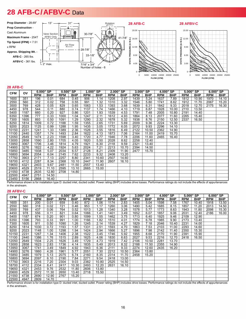
Prop Diameter - 28.69”
Prop Construction -
Cast Aluminum
Maximum Frame - 254T
Tip Speed (FPM) = 7.51
x RPM
Approx. Shipping Wt. -AFB-C - 265 lbs.
AFBV-C - 361 lbs.
28 AFB-C / AFBV-C Data Rotation
Air Flow
Vane SectionAFBV Only
31”
28-7/8”
33-1/8”
30-7/8”41-7/8”
7/16” x 3/4” Number of holes - 6
13”
2” max.
28 AFB-C
Performance shown is for installation type D: ducted inlet, ducted outlet. Power rating (BHP) includes drive losses. Performance ratings do not include the effects of appurtenances in the airstream.
CFM OV 0.000” SP 0.500” SP 1.000” SP 2.000” SP 3.000” SP 4.000” SP 5.000” SP 6.000” SPRPM BHP RPM BHP RPM BHP RPM BHP RPM BHP RPM BHP RPM BHP RPM BHP
1600 351 196 0.01 684 0.45 906 1.14 1208 2.97 1439 5.24 1637 7.89 1812 10.90 1970 14.102550 560 312 0.02 758 0.55 991 1.32 1310 3.32 1546 5.80 1741 8.62 1912 11.70 2067 15.203500 769 428 0.05 829 0.65 1063 1.53 1393 3.68 1639 6.31 1842 9.33 2018 12.70 2175 16.304450 978 544 0.11 880 0.74 1137 1.74 1466 4.10 1719 6.87 1928 10.00 2110 13.505400 1187 660 0.20 927 0.86 1201 1.93 1539 4.53 1791 7.48 2005 10.80 2191 14.406350 1396 777 0.33 1000 1.04 1247 2.11 1612 4.93 1864 8.13 2077 11.60 2265 15.407300 1605 893 0.50 1091 1.29 1290 2.32 1678 5.32 1938 8.76 2150 12.50 2337 16.508250 1814 1009 0.72 1188 1.59 1355 2.65 1731 5.69 2009 9.36 2224 13.309200 2023 1125 0.99 1288 1.95 1435 3.05 1772 6.05 2072 9.93 2296 14.10
10150 2231 1241 1.33 1389 2.36 1526 3.55 1816 6.49 2122 10.50 2362 14.9011100 2440 1357 1.74 1493 2.84 1622 4.13 1873 7.06 2164 11.00 2419 15.7012050 2649 1474 2.23 1598 3.40 1720 4.77 1946 7.78 2206 11.60 2465 16.4013000 2858 1590 2.80 1705 4.05 1820 5.50 2028 8.62 2258 12.4013950 3067 1706 3.46 1814 4.79 1921 6.30 2118 9.59 2321 13.4014900 3276 1822 4.22 1924 5.63 2024 7.21 2213 10.70 2394 14.5015850 3485 1938 5.07 2034 6.57 2128 8.21 2309 11.90 2477 15.7016800 3694 2054 6.04 2145 7.62 2233 9.32 2408 13.2017750 3903 2171 7.13 2257 8.80 2341 10.60 2507 14.6018700 4112 2287 8.34 2368 10.10 2447 11.90 2607 16.1019650 4321 2403 9.67 2481 11.50 2557 13.4020600 4529 2519 11.10 2595 13.10 2665 15.0021550 4738 2635 12.80 2708 14.8022500 4947 2751 14.5023450 5156 2868 16.40
28 AFBV-C
Performance shown is for installation type D: ducted inlet, ducted outlet. Power rating (BHP) includes drive losses. Performance ratings do not include the effects of appurtenances in the airstream.
CFM OV 0.000” SP 0.500” SP 1.000” SP 2.000” SP 3.000” SP 4.000” SP 5.000” SP 6.000” SPRPM BHP RPM BHP RPM BHP RPM BHP RPM BHP RPM BHP RPM BHP RPM BHP
1600 351 200 0.01 659 0.40 872 1.06 1174 2.83 1405 5.04 1598 7.58 1767 10.40 1918 13.502550 560 318 0.02 721 0.46 953 1.17 1260 3.06 1490 5.42 1685 8.15 1857 11.20 2013 14.503500 769 437 0.06 764 0.52 1013 1.28 1340 3.28 1578 5.77 1773 8.63 1943 11.80 2098 15.304450 978 556 0.11 821 0.64 1066 1.41 1401 3.49 1652 6.07 1857 9.06 2031 12.40 2186 16.005400 1187 674 0.20 901 0.80 1099 1.55 1462 3.75 1713 6.40 1925 9.46 2109 12.906350 1396 793 0.33 991 1.00 1166 1.82 1510 4.01 1774 6.78 1985 9.90 2173 13.407300 1605 911 0.50 1090 1.26 1245 2.14 1539 4.27 1829 7.18 2046 10.40 2231 14.008250 1814 1030 0.72 1193 1.57 1331 2.51 1593 4.70 1863 7.53 2103 11.00 2293 14.609200 2023 1148 1.00 1298 1.94 1424 2.94 1666 5.27 1896 7.98 2142 11.40 2350 15.30
10150 2231 1267 1.34 1406 2.38 1522 3.45 1746 5.92 1955 8.68 2170 11.90 2391 15.9011100 2440 1386 1.76 1515 2.89 1625 4.06 1830 6.63 2027 9.53 2216 12.70 2418 16.5012050 2649 1504 2.25 1626 3.49 1729 4.73 1919 7.42 2106 10.50 2281 13.7013000 2858 1623 2.83 1736 4.14 1835 5.49 2013 8.32 2188 11.50 2355 14.9013950 3067 1741 3.49 1849 4.92 1943 6.36 2111 9.33 2274 12.60 2435 16.2014900 3276 1860 4.26 1961 5.77 2051 7.30 2212 10.50 2364 13.8015850 3485 1979 5.13 2075 6.74 2160 8.35 2314 11.70 2458 15.2016800 3694 2097 6.10 2190 7.84 2271 9.54 2418 13.0017750 3903 2216 7.20 2304 9.03 2382 10.80 2525 14.5018700 4112 2334 8.41 2417 10.30 2493 12.20 2631 16.1019650 4321 2453 9.76 2532 11.80 2606 13.8020600 4529 2572 11.30 2650 13.40 2718 15.5021550 4738 2690 12.90 2767 15.2022500 4947 2809 14.70
FLOW (CFM)
STAT
IC P
RES
SUR
E (In
W.G
.)
0 5000 10000 15000 20000 25000
15.00
12.00
9.00
6.00
3.00
0
2868 RPM M
ax
200 RPM
2600 RPM
2 HP
2300 RPM
3 HP
2000 RPM
5 HP
1700 RPM 7.5 HP
1400 RPM
10 HP 1100 RPM
15 HP
800 RPM
28 AFBV-C
FLOW (CFM)
STAT
IC P
RES
SUR
E (In
W.G
.)
0 5000 10000 15000 20000 25000
20.00
16.00
12.00
8.00
4.00
0
P
2868 RM Max
196 RPM
2600 RPM 2300 RPM
3 HP
2000 RPM
5 HP
1700 RPM
7.5 HP
1400 RPM
10 HP 1100 RPM
15 HP
800 RPM
28 AFB-C
17
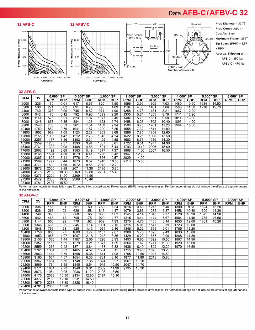
Data AFB-C / AFBV-C 32Prop Diameter - 32.75”
Prop Construction -
Cast Aluminum
Maximum Frame - 254T
Tip Speed (FPM) = 8.57
x RPM
Approx. Shipping Wt. -AFB-C - 350 lbs.
AFBV-C - 470 lbs.
Rotation
Air Flow
Vane SectionAFBV Only
34”
33”
37-1/4”
35”45-1/4”
7/16” x 3/4” Number of holes - 6
15”
2” max.
32 AFB-C
Performance shown is for installation type D: ducted inlet, ducted outlet. Power rating (BHP) includes drive losses. Performance ratings do not include the effects of appurtenances in the airstream.
CFM OV 0.000” SP 0.500” SP 1.000” SP 2.000” SP 3.000” SP 4.000” SP 5.000” SP 6.000” SPRPM BHP RPM BHP RPM BHP RPM BHP RPM BHP RPM BHP RPM BHP RPM BHP
2000 336 170 0.01 617 0.57 820 1.50 1096 3.96 1305 7.03 1480 10.60 1634 14.503200 538 271 0.02 691 0.70 895 1.69 1184 4.35 1401 7.66 1580 11.50 1736 15.704400 740 373 0.06 745 0.82 971 1.96 1258 4.73 1481 8.21 1667 12.205600 942 475 0.12 792 0.96 1029 2.20 1335 5.24 1553 8.79 1741 12.906800 1144 576 0.21 823 1.07 1077 2.45 1404 5.78 1631 9.58 1814 13.808000 1346 678 0.35 884 1.26 1123 2.74 1458 6.26 1702 10.40 1893 14.909200 1548 780 0.53 961 1.54 1150 2.94 1506 6.75 1761 11.20 1964 16.00
10400 1750 882 0.76 1041 1.87 1200 3.25 1555 7.32 1811 11.9011600 1952 983 1.05 1125 2.28 1268 3.69 1596 7.85 1858 12.6012800 2155 1085 1.42 1212 2.76 1345 4.24 1622 8.25 1906 13.5014000 2357 1187 1.86 1302 3.31 1425 4.88 1663 8.78 1949 14.3015200 2559 1288 2.37 1393 3.94 1507 5.61 1722 9.51 1977 14.9016400 2761 1390 2.98 1488 4.68 1591 6.44 1793 10.40 2006 15.6017600 2963 1492 3.69 1583 5.49 1677 7.37 1868 11.50 2057 16.5018800 3165 1594 4.50 1679 6.41 1766 8.42 1947 12.7020000 3367 1695 5.41 1776 7.44 1856 9.57 2029 14.0021200 3569 1797 6.44 1873 8.57 1948 10.80 2110 15.5022400 3771 1899 7.60 1972 9.86 2042 12.2023600 3973 2000 8.88 2071 11.30 2136 13.8024800 4175 2102 10.30 2169 12.80 2231 15.4026000 4377 2204 11.90 2269 14.5027200 4579 2306 13.60 2369 16.4028400 4781 2407 15.50
32 AFBV-C
Performance shown is for installation type D: ducted inlet, ducted outlet. Power rating (BHP) includes drive losses. Performance ratings do not include the effects of appurtenances in the airstream.
CFM OV 0.000” SP 0.500” SP 1.000” SP 2.000” SP 3.000” SP 4.000” SP 5.000” SP 6.000” SPRPM BHP RPM BHP RPM BHP RPM BHP RPM BHP RPM BHP RPM BHP RPM BHP
2000 336 166 .01 561 .50 750 1.34 1016 3.60 1215 6.40 1380 9.61 1524 13.203200 538 266 .02 629 .58 815 1.47 1079 3.86 1285 6.87 1458 10.40 1609 14.304400 740 366 .06 668 .65 883 1.63 1145 4.14 1348 7.27 1520 10.90 1673 14.905600 942 466 .12 705 .75 929 1.77 1215 4.44 1414 7.67 1584 11.40 1735 15.606800 1144 566 .22 770 .92 959 1.93 1275 4.75 1485 8.14 1653 12.00 1801 16.208000 1346 666 .35 845 1.14 1001 2.15 1315 5.01 1547 8.59 1723 12.609200 1548 765 .53 925 1.43 1064 2.46 1345 5.32 1593 9.01 1785 13.20
10400 1750 865 .77 1009 1.77 1137 2.87 1380 5.70 1626 9.43 1833 13.8011600 1953 965 1.07 1097 2.18 1213 3.36 1429 6.20 1655 9.90 1868 14.3012800 2155 1065 1.44 1187 2.65 1293 3.93 1493 6.85 1692 10.50 1897 14.9014000 2357 1165 1.89 1279 3.21 1377 4.59 1564 7.62 1741 11.30 1929 15.6015200 2559 1265 2.42 1371 3.84 1463 5.32 1638 8.49 1802 12.20 1970 16.5016400 2761 1364 3.03 1465 4.57 1551 6.15 1715 9.48 1870 13.2017600 2963 1464 3.75 1558 5.38 1641 7.08 1795 10.60 1943 14.5018800 3165 1564 4.57 1654 6.33 1731 8.10 1877 11.80 2018 15.8020000 3367 1664 5.50 1748 7.35 1824 9.27 1961 13.2021200 3569 1764 6.55 1845 8.54 1916 10.50 2047 14.7022400 3771 1864 7.73 1940 9.81 2009 11.90 2135 16.3023600 3973 1964 9.05 2036 11.20 2103 13.5024800 4175 2063 10.50 2134 12.80 2197 15.1026000 4377 2163 12.10 2231 14.5027200 4579 2263 13.80 2328 16.4028400 4781 2363 15.80
FLOW (CFM)
STAT
IC P
RES
SUR
E (In
W.G
.)
0 6000 12000 18000 24000 30000
15.00
12.00
9.00
6.00
3.00
0
2407 RPM M
ax
2 HP 166 RPM 3 HP
2200 RPM
5 HP
1900 RPM
7.5 HP
1700 RPM
10 HP
1400 RPM 15 HP
1200 RPM 900 RPM 700 RPM
32 AFBV-C
FLOW (CFM)
STAT
IC P
RES
SUR
E (In
W.G
.)
0 6000 12000 18000 24000 30000
15.00
12.00
9.00
6.00
3.00
0
2407 RPM M
ax
2 HP 170 RPM
3 HP
2200 RPM
5 HP
1900 RPM
7.5 HP
1700 RPM
10 HP
1400 RPM
15 HP
1200 RPM 900 RPM 700 RPM
32 AFB-C
18
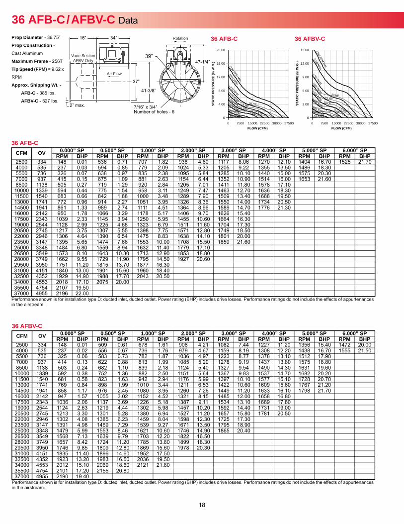
Prop Diameter - 36.75”
Prop Construction -
Cast Aluminum
Maximum Frame - 256T
Tip Speed (FPM) = 9.62 x
RPM
Approx. Shipping Wt. -AFB-C - 385 lbs.
AFBV-C - 527 lbs.
36 AFB-C / AFBV-C Data Rotation
Air Flow
Vane SectionAFBV Only
34”
37”
41-3/8”
39”47-1/4”
7/16” x 3/4” Number of holes - 6
16”
2” max.
36 AFB-C
Performance shown is for installation type D: ducted inlet, ducted outlet. Power rating (BHP) includes drive losses. Performance ratings do not include the effects of appurtenances in the airstream.
CFM OV 0.000” SP 0.500” SP 1.000” SP 2.000” SP 3.000” SP 4.000” SP 5.000” SP 6.000” SPRPM BHP RPM BHP RPM BHP RPM BHP RPM BHP RPM BHP RPM BHP RPM BHP
2500 334 148 0.01 536 0.71 707 1.82 938 4.60 1117 8.06 1270 12.10 1404 16.70 1525 21.704000 535 237 0.03 594 0.85 779 2.09 1024 5.33 1205 9.22 1355 13.50 1486 18.305500 736 326 0.07 638 0.97 835 2.38 1095 5.84 1285 10.10 1440 15.00 1575 20.307000 937 415 0.15 675 1.09 881 2.63 1154 6.44 1352 10.90 1514 16.00 1653 21.608500 1138 505 0.27 719 1.29 920 2.84 1205 7.01 1411 11.80 1578 17.10
10000 1339 594 0.44 775 1.54 958 3.11 1249 7.47 1463 12.70 1636 18.3011500 1540 683 0.66 842 1.88 1000 3.48 1289 7.90 1509 13.40 1688 19.5013000 1741 772 0.96 914 2.27 1051 3.95 1326 8.36 1550 14.00 1734 20.5014500 1941 861 1.33 989 2.74 1111 4.51 1364 8.96 1589 14.70 1776 21.3016000 2142 950 1.78 1066 3.29 1178 5.17 1406 9.70 1626 15.4017500 2343 1039 2.33 1145 3.94 1250 5.95 1455 10.60 1664 16.3019000 2544 1128 2.99 1225 4.68 1323 6.79 1511 11.60 1704 17.3020500 2745 1217 3.75 1307 5.55 1398 7.75 1571 12.80 1749 18.5022000 2946 1306 4.64 1390 6.54 1475 8.83 1638 14.10 1801 20.0023500 3147 1395 5.65 1474 7.66 1553 10.00 1708 15.50 1859 21.6025000 3348 1484 6.80 1559 8.94 1632 11.40 1779 17.1026500 3549 1573 8.10 1643 10.30 1713 12.90 1853 18.8028000 3749 1662 9.55 1729 11.90 1795 14.50 1927 20.6029500 3950 1751 11.20 1815 13.70 1877 16.3031000 4151 1840 13.00 1901 15.60 1960 18.4032500 4352 1929 14.90 1988 17.70 2043 20.5034000 4553 2018 17.10 2075 20.0035500 4754 2107 19.5037000 4955 2196 22.00
36 AFBV-C
Performance shown is for installation type D: ducted inlet, ducted outlet. Power rating (BHP) includes drive losses. Performance ratings do not include the effects of appurtenances in the airstream.
CFM OV 0.000” SP 0.500” SP 1.000” SP 2.000” SP 3.000” SP 4.000” SP 5.000” SP 6.000” SPRPM BHP RPM BHP RPM BHP RPM BHP RPM BHP RPM BHP RPM BHP RPM BHP
2500 334 148 0.01 509 0.61 678 1.61 908 4.21 1082 7.44 1227 11.20 1356 15.40 1472 20.004000 535 237 0.02 556 0.67 736 1.76 979 4.67 1159 8.19 1308 12.20 1438 16.70 1555 21.505500 736 325 0.06 583 0.73 782 1.87 1036 4.97 1223 8.77 1378 13.10 1512 17.907000 937 414 0.13 622 0.88 813 1.99 1085 5.20 1278 9.19 1437 13.80 1575 18.808500 1138 503 0.24 682 1.10 839 2.18 1124 5.40 1327 9.54 1490 14.30 1631 19.60
10000 1339 592 0.38 752 1.36 882 2.50 1151 5.64 1367 9.83 1537 14.70 1682 20.2011500 1540 681 0.58 823 1.63 942 2.94 1176 5.99 1397 10.10 1577 15.10 1728 20.7013000 1741 769 0.84 898 1.99 1010 3.44 1211 6.53 1422 10.60 1609 15.60 1767 21.2014500 1941 858 1.17 976 2.45 1080 3.95 1260 7.26 1449 11.20 1633 16.10 1798 21.7016000 2142 947 1.57 1055 3.02 1152 4.52 1321 8.15 1485 12.00 1658 16.8017500 2343 1036 2.06 1137 3.69 1226 5.18 1387 9.11 1534 13.10 1689 17.8019000 2544 1124 2.63 1219 4.44 1302 5.98 1457 10.20 1592 14.40 1731 19.0020500 2745 1213 3.30 1301 5.28 1380 6.94 1527 11.20 1657 15.80 1781 20.5022000 2946 1302 4.08 1385 6.23 1459 8.04 1598 12.30 1725 17.3023500 3147 1391 4.98 1469 7.29 1539 9.27 1671 13.50 1795 18.9025000 3348 1479 5.99 1553 8.46 1621 10.60 1746 14.90 1865 20.4026500 3549 1568 7.13 1639 9.79 1703 12.20 1822 16.5028000 3749 1657 8.42 1724 11.20 1785 13.80 1899 18.3029500 3950 1746 9.85 1809 12.80 1869 15.60 1978 20.3031000 4151 1835 11.40 1896 14.60 1952 17.5032500 4352 1923 13.20 1983 16.50 2036 19.5034000 4553 2012 15.10 2069 18.60 2121 21.8035500 4754 2101 17.20 2155 20.8037000 4955 2190 19.40
FLOW (CFM)
STAT
IC P
RES
SUR
E (In
W.G
.)
0 7500 15000 22500 30000 37500
15.00
12.00
9.00
6.00
3.00
0
2196 RPM M
ax
2 HP 148 RPM
3 HP
2000 RPM
5 HP
1700 RPM
7.5 HP
1500 RPM
10 HP
1300 RPM 15 HP 1100 RPM
20 HP
800 RPM 600 RPM
36 AFBV-C
FLOW (CFM)
STAT
IC P
RES
SUR
E (In
W.G
.)
0 7500 15000 22500 30000 37500
20.00
16.00
12.00
8.00
4.00
0
2196 RPM Max
148 RPM
2000 RPM
5 HP
1700 RPM
7.5 HP
1500 RPM
10 HP
1300 RPM 15 HP 1100 RPM
20 HP
800 RPMP
600 R M
36 AFB-C
Size no
t ava
ilable
19
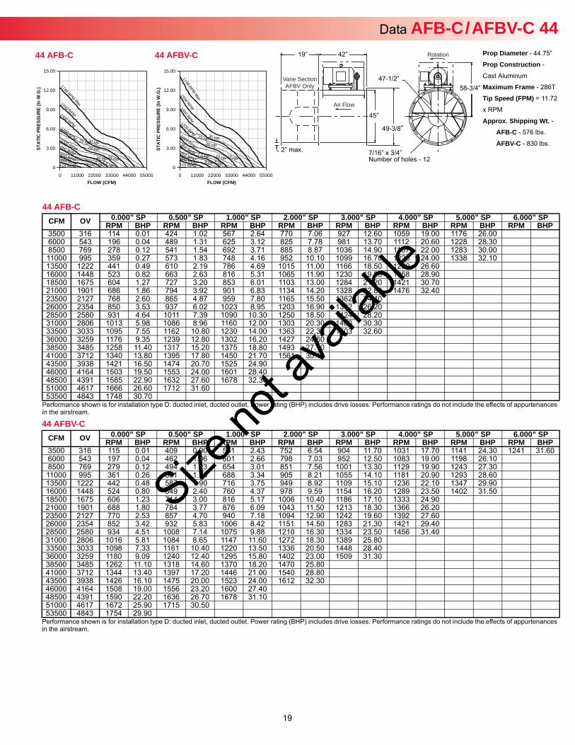
Data AFB-C / AFBV-C 44Prop Diameter - 44.75”
Prop Construction -
Cast Aluminum
Maximum Frame - 286T
Tip Speed (FPM) = 11.72
x RPM
Approx. Shipping Wt. -AFB-C - 576 lbs.
AFBV-C - 830 lbs.
Rotation
Air Flow
Vane SectionAFBV Only
42”
45”
49-3/8”
47-1/2”58-3/4”
7/16” x 3/4” Number of holes - 12
19”
2” max.
44 AFB-C
Performance shown is for installation type D: ducted inlet, ducted outlet. Power rating (BHP) includes drive losses. Performance ratings do not include the effects of appurtenances in the airstream.
CFM OV 0.000” SP 0.500” SP 1.000” SP 2.000” SP 3.000” SP 4.000” SP 5.000” SP 6.000” SPRPM BHP RPM BHP RPM BHP RPM BHP RPM BHP RPM BHP RPM BHP RPM BHP
3500 316 114 0.01 424 1.02 567 2.64 770 7.06 927 12.60 1059 19.00 1176 26.006000 543 196 0.04 489 1.31 625 3.12 825 7.78 981 13.70 1112 20.60 1228 28.308500 769 278 0.12 541 1.54 692 3.71 885 8.87 1036 14.90 1167 22.00 1283 30.0011000 995 359 0.27 573 1.83 748 4.16 952 10.10 1099 16.70 1225 24.00 1338 32.1013500 1222 441 0.49 610 2.19 786 4.69 1015 11.00 1166 18.50 1290 26.6016000 1448 523 0.82 663 2.63 816 5.31 1065 11.90 1230 19.90 1358 28.9018500 1675 604 1.27 727 3.20 853 6.01 1103 13.00 1284 21.20 1421 30.7021000 1901 686 1.86 794 3.92 901 6.83 1134 14.20 1328 22.80 1476 32.4023500 2127 768 2.60 865 4.87 959 7.80 1165 15.50 1362 24.4026000 2354 850 3.53 937 6.02 1023 8.95 1203 16.90 1392 26.2028500 2580 931 4.64 1011 7.39 1090 10.30 1250 18.50 1424 28.2031000 2806 1013 5.98 1086 8.96 1160 12.00 1303 20.30 1460 30.3033500 3033 1095 7.55 1162 10.80 1230 14.00 1363 22.30 1503 32.6036000 3259 1176 9.35 1239 12.80 1302 16.20 1427 24.6038500 3485 1258 11.40 1317 15.20 1375 18.80 1493 27.1041000 3712 1340 13.80 1395 17.80 1450 21.70 1561 30.1043500 3938 1421 16.50 1474 20.70 1525 24.9046000 4164 1503 19.50 1553 24.00 1601 28.4048500 4391 1585 22.90 1632 27.60 1678 32.3051000 4617 1666 26.60 1712 31.6053500 4843 1748 30.70
44 AFBV-C
Performance shown is for installation type D: ducted inlet, ducted outlet. Power rating (BHP) includes drive losses. Performance ratings do not include the effects of appurtenances in the airstream.
CFM OV 0.000” SP 0.500” SP 1.000” SP 2.000” SP 3.000” SP 4.000” SP 5.000” SP 6.000” SPRPM BHP RPM BHP RPM BHP RPM BHP RPM BHP RPM BHP RPM BHP RPM BHP
3500 316 115 0.01 409 0.90 551 2.43 752 6.54 904 11.70 1031 17.70 1141 24.30 1241 31.606000 543 197 0.04 462 1.06 601 2.66 798 7.03 952 12.50 1083 19.00 1198 26.108500 769 279 0.12 494 1.23 654 3.01 851 7.56 1001 13.30 1129 19.90 1243 27.3011000 995 361 0.26 531 1.50 688 3.34 905 8.21 1055 14.10 1181 20.90 1293 28.6013500 1222 442 0.48 587 1.90 716 3.75 949 8.92 1109 15.10 1236 22.10 1347 29.9016000 1448 524 0.80 649 2.40 760 4.37 978 9.59 1154 16.20 1289 23.50 1402 31.5018500 1675 606 1.23 714 3.00 816 5.17 1006 10.40 1186 17.10 1333 24.9021000 1901 688 1.80 784 3.77 876 6.09 1043 11.50 1213 18.30 1366 26.2023500 2127 770 2.53 857 4.70 940 7.18 1094 12.90 1242 19.60 1392 27.6026000 2354 852 3.42 932 5.83 1006 8.42 1151 14.50 1283 21.30 1421 29.4028500 2580 934 4.51 1008 7.14 1075 9.88 1210 16.30 1334 23.50 1456 31.4031000 2806 1016 5.81 1084 8.65 1147 11.60 1272 18.30 1389 25.8033500 3033 1098 7.33 1161 10.40 1220 13.50 1336 20.50 1448 28.4036000 3259 1180 9.09 1240 12.40 1295 15.80 1402 23.00 1509 31.3038500 3485 1262 11.10 1318 14.60 1370 18.20 1470 25.8041000 3712 1344 13.40 1397 17.20 1446 21.00 1540 28.8043500 3938 1426 16.10 1475 20.00 1523 24.00 1612 32.3046000 4164 1508 19.00 1556 23.20 1600 27.4048500 4391 1590 22.20 1636 26.70 1678 31.1051000 4617 1672 25.90 1715 30.5053500 4843 1754 29.90
FLOW (CFM)
STAT
IC P
RES
SUR
E (In
W.G
.)
0 11000 22000 33000 44000 55000
15.00
12.00
9.00
6.00
3.00
0
1748 RPM Max
115 RPM 3 HP
1550 RPM
5 HP
1400 RPM
7.5 HP
1200 RPM
10 HP
1000 RPM
15 HP
850 RPM
20 HP
650 RPM
25 HP
500 RPM
30 HP
44 AFBV-C
FLOW (CFM)
STAT
IC P
RES
SUR
E (In
W.G
.)
0 11000 22000 33000 44000 55000
15.00
12.00
9.00
6.00
3.00
0
1748 RPM Max
114 RPM 3 HP
1550 RPM
5 HP
1400 RPM
7.5 HP
1200 RPM
10 HP
1000 RPM
15 HP
850 RPM 20 HP
650 RPM
25 HP
450 RPM
30 HP
44 AFB-C
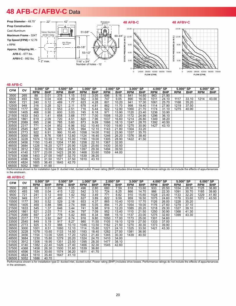
20
Prop Diameter - 48.75”
Prop Construction -
Cast Aluminum
Maximum Frame - 324T
Tip Speed (FPM) = 12.76
x RPM
Approx. Shipping Wt. -AFB-C - 677 lbs.
AFBV-C - 992 lbs.
Rotation
Air Flow
Vane SectionAFBV Only
42”
49-1/8”
53-1/2”
51-5/8”60-3/4”
7/16” x 3/4” Number of holes - 12
22”
2” max.
48 AFB-C / AFBV-C Data
48 AFB-C
Performance shown is for installation type D: ducted inlet, ducted outlet. Power rating (BHP) includes drive losses. Performance ratings do not include the effects of appurtenances in the airstream.
CFM OV 0.000” SP 0.500” SP 1.000” SP 2.000” SP 3.000” SP 4.000” SP 5.000” SP 6.000” SPRPM BHP RPM BHP RPM BHP RPM BHP RPM BHP RPM BHP RPM BHP RPM BHP
3500 265 88 0.01 378 1.15 510 3.05 696 8.16 841 14.60 963 21.906500 493 164 0.04 436 1.49 562 3.56 747 9.05 890 16.00 1011 24.10 1117 33.10 1214 43.009500 721 240 0.12 489 1.77 623 4.28 801 10.20 941 17.30 1061 25.70 1168 35.20
12500 949 316 0.28 521 2.11 678 4.81 862 11.70 998 19.40 1114 27.90 1219 37.5015500 1177 392 0.53 553 2.51 716 5.44 922 12.90 1060 21.70 1174 31.10 1275 40.9018500 1405 468 0.90 600 3.03 745 6.18 971 13.90 1120 23.40 1236 33.9021500 1633 543 1.41 658 3.68 777 7.00 1008 15.20 1172 24.90 1296 36.1024500 1861 619 2.09 720 4.51 820 7.96 1037 16.60 1214 26.80 1349 38.2027500 2089 695 2.96 785 5.60 873 9.09 1066 18.10 1247 28.70 1392 40.5030500 2317 771 4.04 852 6.96 932 10.40 1100 19.80 1275 30.90 1427 43.1033500 2545 847 5.36 920 8.55 994 12.10 1143 21.80 1304 33.2036500 2773 922 6.91 990 10.40 1058 14.00 1192 23.90 1337 35.7039500 3000 998 8.76 1061 12.60 1124 16.40 1246 26.20 1376 38.4042500 3228 1074 10.90 1132 15.00 1190 19.00 1305 28.90 1422 41.5045500 3456 1150 13.40 1204 17.80 1258 22.10 1367 32.0048500 3684 1226 16.20 1277 20.90 1328 25.60 1430 35.5051500 3912 1302 19.50 1350 24.50 1397 29.30 1494 39.5054500 4140 1377 23.00 1423 28.30 1468 33.60 1559 44.0057500 4368 1453 27.00 1497 32.70 1539 38.2060500 4596 1529 31.50 1571 37.50 1610 43.1063500 4824 1605 36.40 1645 42.7066500 5052 1681 41.90
48 AFBV-C
Performance shown is for installation type D: ducted inlet, ducted outlet. Power rating (BHP) includes drive losses. Performance ratings do not include the effects of appurtenances in the airstream.
CFM OV 0.000” SP 0.500” SP 1.000” SP 2.000” SP 3.000” SP 4.000” SP 5.000” SP 6.000” SPRPM BHP RPM BHP RPM BHP RPM BHP RPM BHP RPM BHP RPM BHP RPM BHP
3500 265 89 0.01 366 1.05 496 2.80 680 7.59 818 13.60 933 20.50 1034 28.30 1125 36.806500 493 165 0.04 415 1.22 542 3.10 724 8.25 866 14.70 986 22.30 1091 30.70 1185 39.809500 721 241 0.12 449 1.42 592 3.49 771 8.82 910 15.60 1028 23.40 1133 32.20 1229 41.80
12500 949 317 0.27 480 1.71 627 3.89 822 9.59 959 16.50 1075 24.60 1178 33.60 1272 43.5015500 1177 393 0.52 529 2.16 653 4.37 865 10.40 1010 17.70 1126 26.00 1228 35.2018500 1405 469 0.88 586 2.74 690 5.05 894 11.20 1054 19.00 1176 27.60 1279 37.1021500 1633 545 1.37 646 3.44 741 5.98 919 12.20 1085 20.20 1218 29.30 1327 39.1024500 1861 621 2.03 711 4.34 797 7.09 952 13.40 1110 21.50 1250 30.90 1368 41.3027500 2089 697 2.87 778 5.42 855 8.34 998 15.10 1137 23.00 1275 32.60 1399 43.3030500 2317 773 3.92 847 6.74 916 9.80 1050 17.00 1173 25.00 1301 34.6033500 2545 849 5.19 917 8.27 980 11.50 1105 19.10 1219 27.50 1333 37.0036500 2773 925 6.72 988 10.10 1046 13.50 1162 21.50 1270 30.30 1373 39.9039500 3000 1001 8.51 1060 12.10 1114 15.80 1221 24.10 1325 33.50 1421 43.3042500 3228 1078 10.60 1133 14.50 1183 18.40 1282 27.00 1381 36.9045500 3456 1154 13.00 1205 17.20 1253 21.40 1345 30.30 1439 40.5048500 3684 1230 15.80 1279 20.20 1324 24.70 1410 34.0051500 3912 1306 18.90 1351 23.50 1395 28.30 1477 38.1054500 4140 1382 22.40 1426 27.40 1466 32.30 1545 42.6057500 4368 1458 26.30 1500 31.60 1539 36.8060500 4596 1534 30.60 1574 36.20 1611 41.7063500 4824 1610 35.40 1647 41.1066500 5052 1686 40.70
FLOW (CFM)
STAT
IC P
RES
SUR
E (In
W.G
.)
0 14000 28000 42000 56000 70000
15.00
12.00
9.00
6.00
3.00
0
1681 RPM Max
5 HP 89 RPM
7.5 HP
1500 RPM
10 HP
1350 RPM
15 HP
1150 RPM
20 HP
950 RPM 25 HP 800 RPM
30 HP
600 RPM
40 HP
450 RPM
48 AFBV-C
FLOW (CFM)
STAT
IC P
RES
SUR
E (In
W.G
.)
0 14000 28000 42000 56000 70000
15.00
12.00
9.00
6.00
3.00
0
1681 RPM Max
5 HP 88 RPM 7.5 HP
1500 RPM
10 HP
1350 RPM
15 HP
1150 RPM
20 HP
950 RPM 25 HP 800 RPM
30 HP
600 RPM
40 HP
450 RPM
48 AFB-C
21
Rotation
Air Flow
Vane SectionAFBV Only
42”
55-3/8”
60-3/4”
57-5/8”51-3/4”
7/16” x 3/4” Number of holes - 12
23”
2-1/2” max.
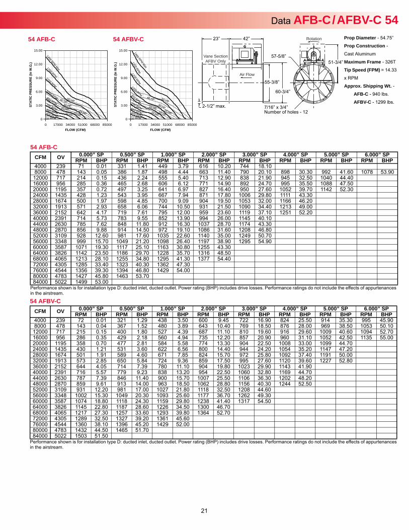
Data AFB-C / AFBV-C 54Prop Diameter - 54.75”
Prop Construction -
Cast Aluminum
Maximum Frame - 326T
Tip Speed (FPM) = 14.33
x RPM
Approx. Shipping Wt. -AFB-C - 940 lbs.
AFBV-C - 1299 lbs.
54 AFB-C
Performance shown is for installation type D: ducted inlet, ducted outlet. Power rating (BHP) includes drive losses. Performance ratings do not include the effects of appurtenances in the airstream.
CFM OV 0.000” SP 0.500” SP 1.000” SP 2.000” SP 3.000” SP 4.000” SP 5.000” SP 6.000” SPRPM BHP RPM BHP RPM BHP RPM BHP RPM BHP RPM BHP RPM BHP RPM BHP
4000 239 71 0.01 331 1.41 449 3.79 616 10.20 744 18.108000 478 143 0.05 386 1.87 498 4.44 663 11.40 790 20.10 898 30.30 992 41.60 1078 53.90
12000 717 214 0.15 436 2.24 555 5.40 713 12.90 838 21.90 945 32.50 1040 44.4016000 956 285 0.36 465 2.68 606 6.12 771 14.90 892 24.70 995 35.50 1088 47.5020000 1195 357 0.72 497 3.25 641 6.97 827 16.40 950 27.60 1052 39.70 1142 52.3024000 1435 428 1.23 543 3.95 667 7.94 871 17.80 1006 29.80 1111 43.3028000 1674 500 1.97 598 4.85 700 9.09 904 19.50 1053 32.00 1166 46.2032000 1913 571 2.93 658 6.06 744 10.50 931 21.50 1090 34.40 1213 49.0036000 2152 642 4.17 719 7.61 795 12.00 959 23.60 1119 37.10 1251 52.2040000 2391 714 5.73 783 9.55 852 13.90 994 26.00 1145 40.1044000 2630 785 7.62 848 11.80 912 16.30 1037 28.70 1174 43.3048000 2870 856 9.88 914 14.50 972 19.10 1086 31.60 1208 46.8052000 3109 928 12.60 981 17.60 1035 22.60 1140 35.00 1249 50.7056000 3348 999 15.70 1049 21.20 1098 26.40 1197 38.90 1295 54.9060000 3587 1071 19.30 1117 25.10 1163 30.80 1255 43.3064000 3826 1142 23.50 1186 29.70 1228 35.70 1316 48.5068000 4065 1213 28.10 1255 34.80 1295 41.30 1377 54.4072000 4305 1285 33.40 1323 40.30 1362 47.3076000 4544 1356 39.30 1394 46.80 1429 54.0080000 4783 1427 45.80 1463 53.7084000 5022 1499 53.00
54 AFBV-C
Performance shown is for installation type D: ducted inlet, ducted outlet. Power rating (BHP) includes drive losses. Performance ratings do not include the effects of appurtenances in the airstream.
CFM OV 0.000” SP 0.500” SP 1.000” SP 2.000” SP 3.000” SP 4.000” SP 5.000” SP 6.000” SPRPM BHP RPM BHP RPM BHP RPM BHP RPM BHP RPM BHP RPM BHP RPM BHP
4000 239 72 0.01 321 1.29 438 3.50 600 9.45 722 16.90 824 25.50 914 35.30 995 45.908000 478 143 0.04 367 1.52 480 3.89 643 10.40 769 18.50 876 28.00 969 38.50 1053 50.10
12000 717 215 0.15 400 1.80 527 4.39 687 11.10 810 19.60 916 29.60 1009 40.60 1094 52.7016000 956 286 0.35 429 2.18 560 4.94 735 12.20 857 20.90 960 31.10 1052 42.50 1135 55.0020000 1195 358 0.70 477 2.81 584 5.58 774 13.30 904 22.50 1008 33.00 1099 44.7024000 1435 430 1.21 531 3.60 622 6.56 800 14.40 944 24.20 1054 35.20 1147 47.2028000 1674 501 1.91 589 4.60 671 7.85 824 15.70 972 25.80 1092 37.40 1191 50.0032000 1913 573 2.85 650 5.84 724 9.36 859 17.50 995 27.60 1120 39.60 1227 52.8036000 2152 644 4.05 714 7.39 780 11.10 904 19.80 1023 29.90 1143 41.9040000 2391 716 5.57 779 9.23 838 13.20 954 22.50 1060 32.80 1169 44.7044000 2630 787 7.39 846 11.40 900 15.70 1007 25.50 1106 36.30 1202 48.2048000 2870 859 9.61 913 14.00 963 18.50 1062 28.80 1156 40.30 1244 52.5052000 3109 931 12.20 981 17.00 1027 21.80 1118 32.50 1208 44.6056000 3348 1002 15.30 1049 20.30 1093 25.60 1177 36.70 1262 49.3060000 3587 1074 18.80 1118 24.30 1159 29.80 1238 41.40 1317 54.5064000 3826 1145 22.80 1187 28.60 1226 34.50 1300 46.7068000 4065 1217 27.30 1257 33.60 1293 39.80 1364 52.7072000 4305 1289 32.50 1327 39.20 1361 45.6076000 4544 1360 38.10 1396 45.20 1429 52.0080000 4783 1432 44.50 1465 51.7084000 5022 1503 51.50
FLOW (CFM)
STAT
IC P
RES
SUR
E (In
W.G
.)
0 17000 34000 51000 68000 85000
15.00
12.00
9.00
6.00
3.00
0
1499 RPM Max
72 RPM
1350 RPM
10 HP
1200 RPM
15 HP
1000 RPM
20 HP
850 RPM
25 HP
700 RPM 30 HP 550 RPM
40 HP
400 RPM
50 HP
54 AFBV-C
FLOW (CFM)
STAT
IC P
RES
SUR
E (In
W.G
.)
0 17000 34000 51000 68000 85000
15.00
12.00
9.00
6.00
3.00
0
1499 RPM Max
71 RPM
1350 RPM
10 HP
1200 RPM
15 HP
1000 RPM
20 HP
850 RPM
25 HP
700 RPM 30 HP
550 RPM
40 HP
400 RPM
50 HP
54 AFB-C
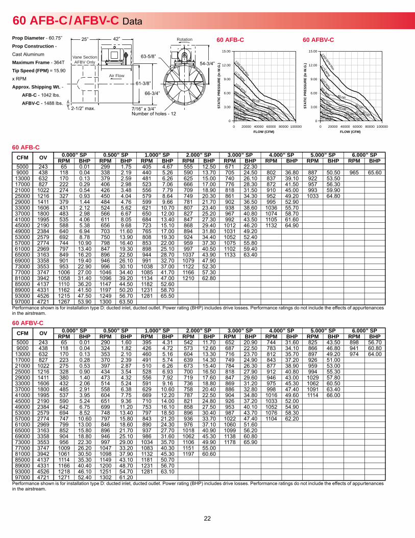
22
60 AFB-C / AFBV-C Data Prop Diameter - 60.75”
Prop Construction -
Cast Aluminum
Maximum Frame - 364T
Tip Speed (FPM) = 15.90
x RPM
Approx. Shipping Wt. -AFB-C - 1042 lbs.
AFBV-C - 1488 lbs.
60 AFB-C
Performance shown is for installation type D: ducted inlet, ducted outlet. Power rating (BHP) includes drive losses. Performance ratings do not include the effects of appurtenances in the airstream.
CFM OV 0.000” SP 0.500” SP 1.000” SP 2.000” SP 3.000” SP 4.000” SP 5.000” SP 6.000” SPRPM BHP RPM BHP RPM BHP RPM BHP RPM BHP RPM BHP RPM BHP RPM BHP
5000 243 65 0.01 299 1.75 405 4.67 555 12.50 671 22.309000 438 118 0.04 338 2.19 440 5.26 590 13.70 705 24.50 802 36.80 887 50.50 965 65.60
13000 632 170 0.13 379 2.59 481 6.26 625 15.00 740 26.10 837 39.10 922 53.5017000 827 222 0.29 406 2.98 523 7.06 666 17.00 776 28.30 872 41.50 957 56.3021000 1022 274 0.54 426 3.48 556 7.79 709 18.90 818 31.50 910 45.00 993 59.9025000 1216 327 0.93 450 4.04 579 8.64 749 20.30 861 34.30 952 49.20 1033 64.8029000 1411 379 1.44 484 4.76 599 9.66 781 21.70 902 36.50 995 52.9033000 1606 431 2.12 524 5.62 621 10.70 807 23.40 938 38.60 1036 55.7037000 1800 483 2.98 566 6.67 650 12.00 827 25.20 967 40.80 1074 58.7041000 1995 535 4.06 611 8.05 684 13.40 847 27.30 992 43.50 1105 61.6045000 2190 588 5.38 656 9.68 723 15.10 868 29.40 1012 46.20 1132 64.9049000 2384 640 6.94 703 11.60 765 17.00 894 31.80 1031 49.2053000 2579 692 8.78 750 13.90 808 19.30 924 34.40 1052 52.4057000 2774 744 10.90 798 16.40 853 22.00 959 37.30 1075 55.8061000 2969 797 13.40 847 19.30 898 25.10 997 40.50 1102 59.4065000 3163 849 16.20 896 22.50 944 28.70 1037 43.90 1133 63.4069000 3358 901 19.40 946 26.10 991 32.70 1079 47.9073000 3553 953 22.90 996 30.10 1038 37.00 1122 52.3077000 3747 1006 27.00 1046 34.40 1085 41.70 1166 57.3081000 3942 1058 31.40 1096 39.20 1134 47.00 1210 62.8085000 4137 1110 36.20 1147 44.50 1182 52.6089000 4331 1162 41.50 1197 50.20 1231 58.7093000 4526 1215 47.50 1249 56.70 1281 65.5097000 4721 1267 53.90 1300 63.50
60 AFBV-C
Performance shown is for installation type D: ducted inlet, ducted outlet. Power rating (BHP) includes drive losses. Performance ratings do not include the effects of appurtenances in the airstream.
CFM OV 0.000” SP 0.500” SP 1.000” SP 2.000” SP 3.000” SP 4.000” SP 5.000” SP 6.000” SPRPM BHP RPM BHP RPM BHP RPM BHP RPM BHP RPM BHP RPM BHP RPM BHP
5000 243 65 0.01 290 1.60 395 4.31 542 11.70 652 20.90 744 31.60 825 43.50 898 56.709000 438 118 0.04 324 1.82 426 4.72 573 12.60 687 22.50 783 34.10 866 46.80 941 60.80
13000 632 170 0.13 353 2.10 460 5.16 604 13.30 716 23.70 812 35.70 897 49.20 974 64.0017000 827 223 0.28 370 2.39 491 5.74 639 14.30 749 24.90 843 37.20 926 51.0021000 1022 275 0.53 397 2.87 510 6.26 673 15.40 784 26.30 877 38.90 959 53.0025000 1216 328 0.90 434 3.54 528 6.93 700 16.50 818 27.90 912 40.80 994 55.3029000 1411 380 1.40 473 4.32 556 7.92 719 17.60 847 29.60 946 43.00 1029 57.8033000 1606 432 2.06 514 5.24 591 9.16 736 18.80 869 31.20 975 45.30 1062 60.5037000 1800 485 2.91 558 6.38 629 10.60 758 20.40 886 32.80 998 47.40 1091 63.4041000 1995 537 3.95 604 7.75 669 12.20 787 22.50 904 34.80 1016 49.60 1114 66.0045000 2190 590 5.24 651 9.36 710 14.00 821 24.80 926 37.20 1033 52.0049000 2384 642 6.75 699 11.20 753 16.10 858 27.50 953 40.10 1052 54.9053000 2579 694 8.52 748 13.40 797 18.50 896 30.40 987 43.70 1076 58.3057000 2774 747 10.60 797 15.80 843 21.20 936 33.70 1022 47.40 1104 62.2061000 2969 799 13.00 846 18.60 890 24.30 976 37.10 1060 51.6065000 3163 852 15.80 896 21.70 937 27.70 1018 40.90 1099 56.2069000 3358 904 18.80 946 25.10 986 31.60 1062 45.30 1138 60.8073000 3553 956 22.30 997 29.00 1034 35.70 1106 49.90 1178 65.9077000 3747 1009 26.20 1047 33.20 1083 40.30 1151 55.0081000 3942 1061 30.50 1098 37.90 1132 45.30 1197 60.6085000 4137 1114 35.30 1149 43.10 1181 50.7089000 4331 1166 40.40 1200 48.70 1231 56.7093000 4526 1218 46.10 1251 54.70 1281 63.1097000 4721 1271 52.40 1302 61.20
Rotation
Air Flow
Vane SectionAFBV Only
42”
61-3/8”
66-3/4”
63-5/8”54-3/4”
7/16” x 3/4” Number of holes - 12
25”
2-1/2” max.
FLOW (CFM)
STAT
IC P
RES
SUR
E (In
W.G
.)
0 20000 40000 60000 80000 100000
15.00
12.00
9.00
6.00
3.00
0
1300 RPM Max
65 RPM
1175 RPM
10 HP
1025 RPM
15 HP
900 RPM
20 HP
750 RPM 25 HP
625 RPM 30 HP 475 RPM
40 HP 350 RPM
50 HP
60 HP
60 AFBV-C
FLOW (CFM)
STAT
IC P
RES
SUR
E (In
W.G
.)
0 20000 40000 60000 80000 100000
15.00
12.00
9.00
6.00
3.00
0
1300 RPM Max
65 RPM
1175 RPM
10 HP
1025 RPM
15 HP
900 RPM
20 HP
750 RPM 25 HP
625 RPM 30 HP 475 RPM
40 HP
350 RPM
50 HP
60 HP
60 AFB-C
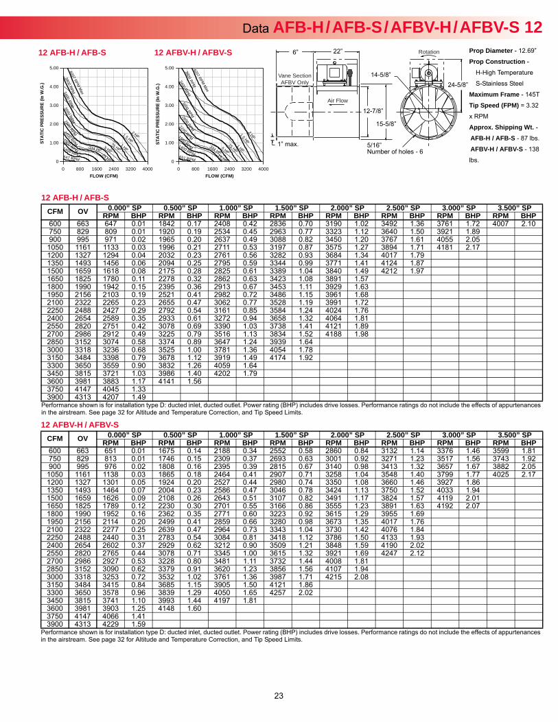
23
Prop Diameter - 12.69”
Prop Construction -
H-High Temperature
S-Stainless Steel
Maximum Frame - 145T
Tip Speed (FPM) = 3.32
x RPM
Approx. Shipping Wt. -AFB-H / AFB-S - 87 lbs.
AFBV-H / AFBV-S - 138
lbs.
Rotation
Air Flow
Vane SectionAFBV Only
22”
12-7/8”
15-5/8”
14-5/8”24-5/8”
5/16” Number of holes - 6
6”
1” max.
Data AFB-H / AFB-S / AFBV-H / AFBV-S 12
12 AFB-H / AFB-S
Performance shown is for installation type D: ducted inlet, ducted outlet. Power rating (BHP) includes drive losses. Performance ratings do not include the effects of appurtenances in the airstream. See page 32 for Altitude and Temperature Correction, and Tip Speed Limits.
CFM OV 0.000” SP 0.500” SP 1.000” SP 1.500” SP 2.000” SP 2.500” SP 3.000” SP 3.500” SPRPM BHP RPM BHP RPM BHP RPM BHP RPM BHP RPM BHP RPM BHP RPM BHP
600 663 647 0.01 1842 0.17 2408 0.42 2836 0.70 3190 1.02 3492 1.36 3761 1.72 4007 2.10750 829 809 0.01 1920 0.19 2534 0.45 2963 0.77 3323 1.12 3640 1.50 3921 1.89900 995 971 0.02 1965 0.20 2637 0.49 3088 0.82 3450 1.20 3767 1.61 4055 2.05
1050 1161 1133 0.03 1996 0.21 2711 0.53 3197 0.87 3575 1.27 3894 1.71 4181 2.171200 1327 1294 0.04 2032 0.23 2761 0.56 3282 0.93 3684 1.34 4017 1.791350 1493 1456 0.06 2094 0.25 2795 0.59 3344 0.99 3771 1.41 4124 1.871500 1659 1618 0.08 2175 0.28 2825 0.61 3389 1.04 3840 1.49 4212 1.971650 1825 1780 0.11 2278 0.32 2862 0.63 3423 1.08 3891 1.571800 1990 1942 0.15 2395 0.36 2913 0.67 3453 1.11 3929 1.631950 2156 2103 0.19 2521 0.41 2982 0.72 3486 1.15 3961 1.682100 2322 2265 0.23 2655 0.47 3062 0.77 3528 1.19 3991 1.722250 2488 2427 0.29 2792 0.54 3161 0.85 3584 1.24 4024 1.762400 2654 2589 0.35 2933 0.61 3272 0.94 3658 1.32 4064 1.812550 2820 2751 0.42 3078 0.69 3390 1.03 3738 1.41 4121 1.892700 2986 2912 0.49 3225 0.79 3516 1.13 3834 1.52 4188 1.982850 3152 3074 0.58 3374 0.89 3647 1.24 3939 1.643000 3318 3236 0.68 3525 1.00 3781 1.36 4054 1.783150 3484 3398 0.79 3678 1.12 3919 1.49 4174 1.923300 3650 3559 0.90 3832 1.26 4059 1.643450 3815 3721 1.03 3986 1.40 4202 1.793600 3981 3883 1.17 4141 1.563750 4147 4045 1.333900 4313 4207 1.49
12 AFBV-H / AFBV-S
Performance shown is for installation type D: ducted inlet, ducted outlet. Power rating (BHP) includes drive losses. Performance ratings do not include the effects of appurtenances in the airstream. See page 32 for Altitude and Temperature Correction, and Tip Speed Limits.
CFM OV 0.000” SP 0.500” SP 1.000” SP 1.500” SP 2.000” SP 2.500” SP 3.000” SP 3.500” SPRPM BHP RPM BHP RPM BHP RPM BHP RPM BHP RPM BHP RPM BHP RPM BHP
600 663 651 0.01 1675 0.14 2188 0.34 2552 0.58 2860 0.84 3132 1.14 3376 1.46 3599 1.81750 829 813 0.01 1746 0.15 2309 0.37 2693 0.63 3001 0.92 3271 1.23 3517 1.56 3743 1.92900 995 976 0.02 1808 0.16 2395 0.39 2815 0.67 3140 0.98 3413 1.32 3657 1.67 3882 2.05
1050 1161 1138 0.03 1865 0.18 2464 0.41 2907 0.71 3258 1.04 3548 1.40 3799 1.77 4025 2.171200 1327 1301 0.05 1924 0.20 2527 0.44 2980 0.74 3350 1.08 3660 1.46 3927 1.861350 1493 1464 0.07 2004 0.23 2586 0.47 3046 0.78 3424 1.13 3750 1.52 4033 1.941500 1659 1626 0.09 2108 0.26 2643 0.51 3107 0.82 3491 1.17 3824 1.57 4119 2.011650 1825 1789 0.12 2230 0.30 2701 0.55 3166 0.86 3555 1.23 3891 1.63 4192 2.071800 1990 1952 0.16 2362 0.35 2771 0.60 3223 0.92 3615 1.29 3955 1.691950 2156 2114 0.20 2499 0.41 2859 0.66 3280 0.98 3673 1.35 4017 1.762100 2322 2277 0.25 2639 0.47 2964 0.73 3343 1.04 3730 1.42 4076 1.842250 2488 2440 0.31 2783 0.54 3084 0.81 3418 1.12 3786 1.50 4133 1.932400 2654 2602 0.37 2929 0.62 3212 0.90 3509 1.21 3848 1.59 4190 2.022550 2820 2765 0.44 3078 0.71 3345 1.00 3615 1.32 3921 1.69 4247 2.122700 2986 2927 0.53 3228 0.80 3481 1.11 3732 1.44 4008 1.812850 3152 3090 0.62 3379 0.91 3620 1.23 3856 1.56 4107 1.943000 3318 3253 0.72 3532 1.02 3761 1.36 3987 1.71 4215 2.083150 3484 3415 0.84 3685 1.15 3905 1.50 4121 1.863300 3650 3578 0.96 3839 1.29 4050 1.65 4257 2.023450 3815 3741 1.10 3993 1.44 4197 1.813600 3981 3903 1.25 4148 1.603750 4147 4066 1.413900 4313 4229 1.59
FLOW (CFM)
STAT
IC P
RES
SUR
E (In
W.G
.)
0 800 1600 2400 3200 4000
5.00
4.00
3.00
2.00
1.00
0
4207 RPM M
ax
.25 HP 651 RPM
.334 HP
3800 RPM
.5 HP
3400 RPM
.75 HP
3000 RPM
1 HP
2600 RPM
1.5 HP
2200 RPM
2 HP 1800 RPM 1400 RPM
12 AFBV-H / AFBV-S
FLOW (CFM)
STAT
IC P
RES
SUR
E (In
W.G
.)
0 800 1600 2400 3200 4000
5.00
4.00
3.00
2.00
1.00
0
4207 RPM M
ax
.25 HP 647 RPM
.334 HP
3800 RPM
.5 HP
3400 RPM
.75 HP
3000 RPM
1 HP
2600 RPM 1.5 HP
2200 RPM
2 HP 1800 RPM 1400 RPM
12 AFB-H / AFB-S
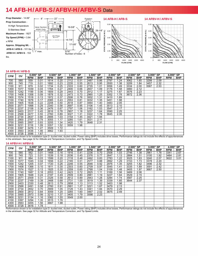
24
14 AFB-H / AFB-S / AFBV-H / AFBV-S Data Prop Diameter - 14.69”
Prop Construction -
H-High Temperature
S-Stainless Steel
Maximum Frame - 182T
Tip Speed (FPM) = 3.84
x RPM
Approx. Shipping Wt. -AFB-H / AFB-S - 101 lbs.
AFBV-H / AFBV-S - 153
lbs.
Rotation
Air Flow
Vane SectionAFBV Only
22”
14-7/8”
17-5/8”
16-5/8”28-1/8”
5/16” Number of holes - 6
8”
1” max.
14 AFB-H / AFB-S
Performance shown is for installation type D: ducted inlet, ducted outlet. Power rating (BHP) includes drive losses. Performance ratings do not include the effects of appurtenances in the airstream. See page 32 for Altitude and Temperature Correction, and Tip Speed Limits.
CFM OV 0.000” SP 0.500” SP 1.000” SP 1.500” SP 2.000” SP 2.500” SP 3.000” SP 4.000” SPRPM BHP RPM BHP RPM BHP RPM BHP RPM BHP RPM BHP RPM BHP RPM BHP
700 580 559 0.01 1614 0.20 2112 0.51 2487 0.86 2797 1.24 3062 1.65 3299 2.09900 745 719 0.01 1692 0.23 2235 0.55 2613 0.95 2930 1.38 3209 1.84 3457 2.321100 911 879 0.02 1734 0.25 2333 0.60 2735 1.01 3056 1.49 3334 2.00 3587 2.531300 1077 1039 0.04 1764 0.27 2400 0.66 2837 1.09 3176 1.58 3460 2.121500 1242 1199 0.06 1809 0.29 2443 0.70 2912 1.17 3275 1.67 3576 2.231700 1408 1358 0.09 1878 0.32 2473 0.73 2965 1.25 3352 1.78 3672 2.361900 1574 1518 0.13 1972 0.37 2506 0.76 3002 1.31 3410 1.892100 1740 1678 0.17 2085 0.43 2553 0.81 3032 1.35 3451 1.982300 1905 1838 0.22 2208 0.50 2618 0.87 3064 1.40 3483 2.052500 2071 1998 0.29 2340 0.58 2697 0.95 3106 1.45 3513 2.102700 2237 2158 0.36 2476 0.67 2797 1.06 3162 1.53 3547 2.172900 2403 2317 0.45 2616 0.78 2907 1.18 3237 1.64 3590 2.253100 2568 2477 0.55 2760 0.89 3027 1.31 3322 1.78 3645 2.353300 2734 2637 0.66 2906 1.03 3154 1.45 3421 1.943500 2900 2797 0.79 3055 1.17 3285 1.61 3531 2.113700 3065 2957 0.93 3205 1.34 3420 1.79 3648 2.313900 3231 3116 1.09 3357 1.52 3559 1.984100 3397 3276 1.27 3509 1.724300 3563 3436 1.46 3662 1.934500 3728 3596 1.67
14 AFBV-H / AFBV-S
Performance shown is for installation type D: ducted inlet, ducted outlet. Power rating (BHP) includes drive losses. Performance ratings do not include the effects of appurtenances in the airstream. See page 32 for Altitude and Temperature Correction, and Tip Speed Limits.
CFM OV 0.000” SP 0.500” SP 1.000” SP 1.500” SP 2.000” SP 2.500” SP 3.000” SP 4.000” SPRPM BHP RPM BHP RPM BHP RPM BHP RPM BHP RPM BHP RPM BHP RPM BHP
700 580 562 0.01 1468 0.16 1916 0.41 2236 0.70 2508 1.03 2746 1.38 2961 1.78 3341 2.67900 745 723 0.01 1539 0.18 2036 0.45 2376 0.77 2647 1.13 2884 1.51 3100 1.92 3484 2.811100 911 884 0.03 1599 0.20 2118 0.48 2492 0.83 2783 1.22 3025 1.63 3240 2.07 3622 3.011300 1077 1045 0.04 1656 0.22 2185 0.51 2577 0.88 2892 1.29 3153 1.73 3378 2.201500 1242 1205 0.07 1720 0.26 2246 0.55 2646 0.92 2976 1.35 3255 1.82 3496 2.321700 1408 1366 0.10 1811 0.30 2303 0.60 2709 0.97 3045 1.41 3335 1.89 3591 2.421900 1574 1527 0.13 1925 0.35 2359 0.65 2768 1.04 3109 1.48 3405 1.97 3667 2.502100 1740 1687 0.18 2053 0.42 2423 0.72 2825 1.11 3169 1.56 3469 2.062300 1905 1848 0.24 2187 0.49 2509 0.80 2881 1.19 3227 1.64 3529 2.152500 2071 2009 0.31 2326 0.58 2612 0.89 2943 1.28 3284 1.74 3587 2.252700 2237 2169 0.39 2468 0.68 2731 1.00 3019 1.39 3339 1.85 3644 2.372900 2403 2330 0.48 2613 0.79 2858 1.13 3113 1.52 3403 1.983100 2568 2491 0.58 2760 0.91 2991 1.27 3221 1.67 3479 2.133300 2734 2652 0.70 2909 1.05 3126 1.43 3341 1.84 3570 2.293500 2900 2812 0.84 3059 1.20 3265 1.60 3467 2.02 3675 2.493700 3065 2973 0.99 3210 1.37 3405 1.79 3598 2.233900 3231 3134 1.16 3362 1.55 3549 2.004100 3397 3294 1.35 3515 1.764300 3563 3455 1.56 3667 1.984500 3728 3616 1.78
FLOW (CFM)
STAT
IC P
RES
SUR
E (In
W.G
.)
0 800 1600 2400 3200 4000
5.00
4.00
3.00
2.00
1.00
0
a
3596 RPM M
x
.25 HP 562 RPM
.334 HP
3300 RPM
.5 HP
2900 RPM
.75 HP
2600 RPM
1 HP
2200 RPM
1.5 HP
1900 RPM
2 HP 1600 RPM
3 HP
1200 RPM
14 AFBV-H / AFBV-S
FLOW (CFM)
STAT
IC P
RES
SUR
E (In
W.G
.)
0 800 1600 2400 3200 4000
5.00
4.00
3.00
2.00
1.00
0
3596 RPM M
ax
.25 HP 559 RPM
.334 HP
3300 RPM
.5 HP
2900 RPM
.75 HP
2600 RPM
1 HP
2200 RPM 1.5 HP
1900 RPM
2 HP 1600 RPM
3 HP
1200 RPM
14 AFB-H / AFB-S
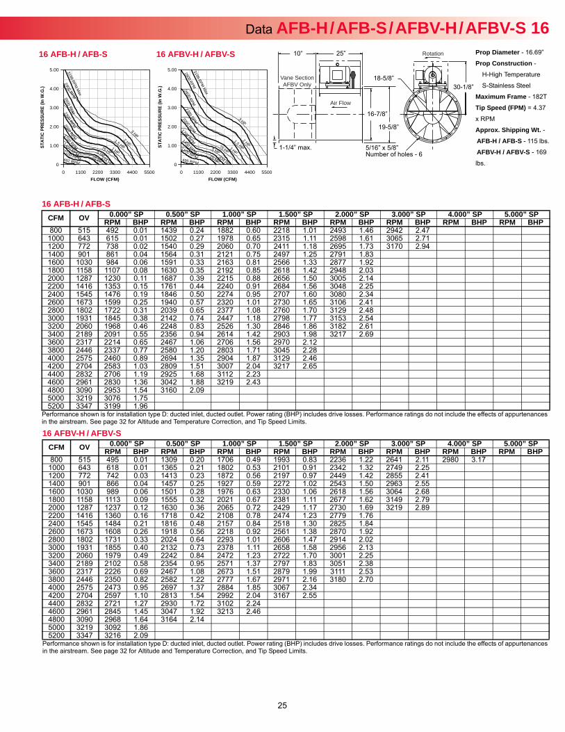
25
Data AFB-H / AFB-S / AFBV-H / AFBV-S 16Prop Diameter - 16.69”
Prop Construction -
H-High Temperature
S-Stainless Steel
Maximum Frame - 182T
Tip Speed (FPM) = 4.37
x RPM
Approx. Shipping Wt. -AFB-H / AFB-S - 115 lbs.
AFBV-H / AFBV-S - 169
lbs.
Rotation
Air Flow
Vane SectionAFBV Only
25”
16-7/8”
19-5/8”
18-5/8”30-1/8”
5/16” x 5/8”Number of holes - 6
10”
1-1/4” max.
16 AFB-H / AFB-S
Performance shown is for installation type D: ducted inlet, ducted outlet. Power rating (BHP) includes drive losses. Performance ratings do not include the effects of appurtenances in the airstream. See page 32 for Altitude and Temperature Correction, and Tip Speed Limits.
CFM OV 0.000” SP 0.500” SP 1.000” SP 1.500” SP 2.000” SP 3.000” SP 4.000” SP 5.000” SPRPM BHP RPM BHP RPM BHP RPM BHP RPM BHP RPM BHP RPM BHP RPM BHP
800 515 492 0.01 1439 0.24 1882 0.60 2218 1.01 2493 1.46 2942 2.471000 643 615 0.01 1502 0.27 1978 0.65 2315 1.11 2598 1.61 3065 2.711200 772 738 0.02 1540 0.29 2060 0.70 2411 1.18 2695 1.73 3170 2.941400 901 861 0.04 1564 0.31 2121 0.75 2497 1.25 2791 1.831600 1030 984 0.06 1591 0.33 2163 0.81 2566 1.33 2877 1.921800 1158 1107 0.08 1630 0.35 2192 0.85 2618 1.42 2948 2.032000 1287 1230 0.11 1687 0.39 2215 0.88 2656 1.50 3005 2.142200 1416 1353 0.15 1761 0.44 2240 0.91 2684 1.56 3048 2.252400 1545 1476 0.19 1846 0.50 2274 0.95 2707 1.60 3080 2.342600 1673 1599 0.25 1940 0.57 2320 1.01 2730 1.65 3106 2.412800 1802 1722 0.31 2039 0.65 2377 1.08 2760 1.70 3129 2.483000 1931 1845 0.38 2142 0.74 2447 1.18 2798 1.77 3153 2.543200 2060 1968 0.46 2248 0.83 2526 1.30 2846 1.86 3182 2.613400 2189 2091 0.55 2356 0.94 2614 1.42 2903 1.98 3217 2.693600 2317 2214 0.65 2467 1.06 2706 1.56 2970 2.123800 2446 2337 0.77 2580 1.20 2803 1.71 3045 2.284000 2575 2460 0.89 2694 1.35 2904 1.87 3129 2.464200 2704 2583 1.03 2809 1.51 3007 2.04 3217 2.654400 2832 2706 1.19 2925 1.68 3112 2.234600 2961 2830 1.36 3042 1.88 3219 2.434800 3090 2953 1.54 3160 2.095000 3219 3076 1.755200 3347 3199 1.96
16 AFBV-H / AFBV-S
Performance shown is for installation type D: ducted inlet, ducted outlet. Power rating (BHP) includes drive losses. Performance ratings do not include the effects of appurtenances in the airstream. See page 32 for Altitude and Temperature Correction, and Tip Speed Limits.
CFM OV 0.000” SP 0.500” SP 1.000” SP 1.500” SP 2.000” SP 3.000” SP 4.000” SP 5.000” SPRPM BHP RPM BHP RPM BHP RPM BHP RPM BHP RPM BHP RPM BHP RPM BHP
800 515 495 0.01 1309 0.20 1706 0.49 1993 0.83 2236 1.22 2641 2.11 2980 3.171000 643 618 0.01 1365 0.21 1802 0.53 2101 0.91 2342 1.32 2749 2.251200 772 742 0.03 1413 0.23 1872 0.56 2197 0.97 2449 1.42 2855 2.411400 901 866 0.04 1457 0.25 1927 0.59 2272 1.02 2543 1.50 2963 2.551600 1030 989 0.06 1501 0.28 1976 0.63 2330 1.06 2618 1.56 3064 2.681800 1158 1113 0.09 1555 0.32 2021 0.67 2381 1.11 2677 1.62 3149 2.792000 1287 1237 0.12 1630 0.36 2065 0.72 2429 1.17 2730 1.69 3219 2.892200 1416 1360 0.16 1718 0.42 2108 0.78 2474 1.23 2779 1.762400 1545 1484 0.21 1816 0.48 2157 0.84 2518 1.30 2825 1.842600 1673 1608 0.26 1918 0.56 2218 0.92 2561 1.38 2870 1.922800 1802 1731 0.33 2024 0.64 2293 1.01 2606 1.47 2914 2.023000 1931 1855 0.40 2132 0.73 2378 1.11 2658 1.58 2956 2.133200 2060 1979 0.49 2242 0.84 2472 1.23 2722 1.70 3001 2.253400 2189 2102 0.58 2354 0.95 2571 1.37 2797 1.83 3051 2.383600 2317 2226 0.69 2467 1.08 2673 1.51 2879 1.99 3111 2.533800 2446 2350 0.82 2582 1.22 2777 1.67 2971 2.16 3180 2.704000 2575 2473 0.95 2697 1.37 2884 1.85 3067 2.344200 2704 2597 1.10 2813 1.54 2992 2.04 3167 2.554400 2832 2721 1.27 2930 1.72 3102 2.244600 2961 2845 1.45 3047 1.92 3213 2.464800 3090 2968 1.64 3164 2.145000 3219 3092 1.865200 3347 3216 2.09
FLOW (CFM)
STAT
IC P
RES
SUR
E (In
W.G
.)
0 1100 2200 3300 4400 5500
5.00
4.00
3.00
2.00
1.00
0
P 3199 R
M M
ax
.25 HP 495 RPM
.334 HP
2900 RPM
.5 HP
2600 RPM
.75 HP
2300 RPM
1 HP
2000 RPM
1.5 HP
1700 RPM 2 HP 1400 RPM
3 HP
1100 RPM
16 AFBV-H / AFBV-S
FLOW (CFM)
STAT
IC P
RES
SUR
E (In
W.G
.)
0 1100 2200 3300 4400 5500
5.00
4.00
3.00
2.00
1.00
0
x
3199 RPM M
a
.25 HP 492 RPM
.334 HP
2900 RPM
.5 HP
2600 RPM
.75 HP
2300 RPM
1 HP
2000 RPM
1.5 HP
1700 RPM
2 HP 1400 RPM
3 HP
1100 RPM
16 AFB-H / AFB-S
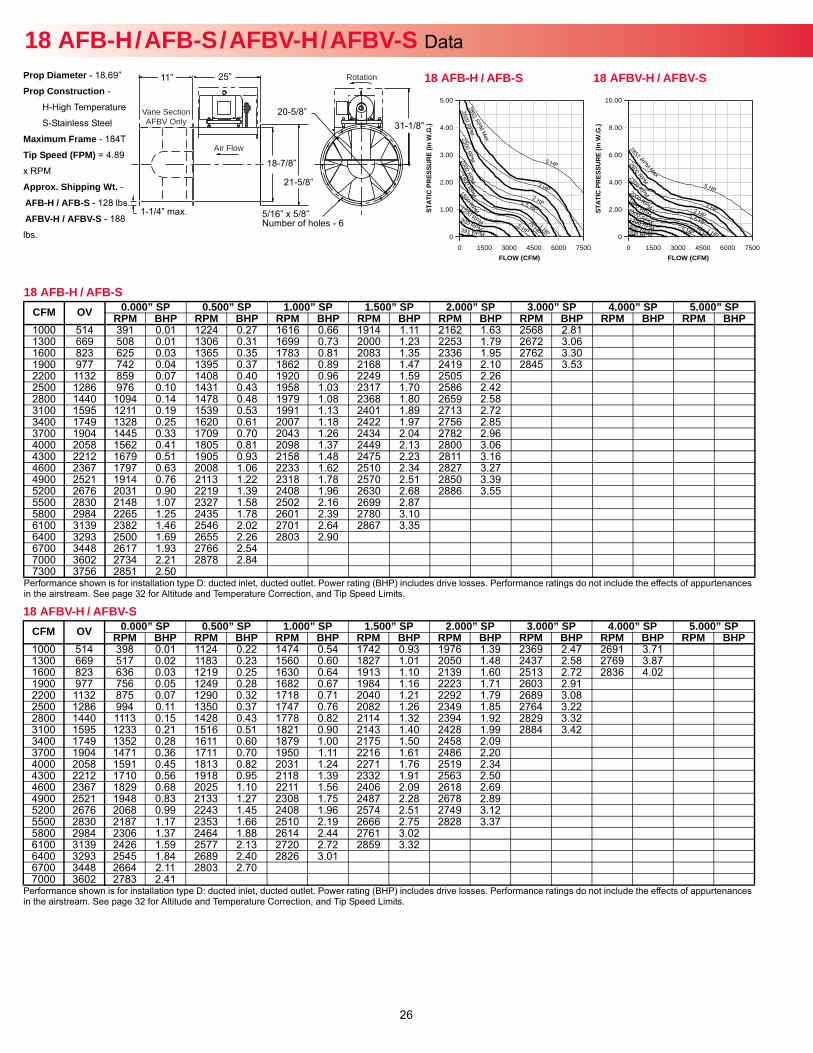
26
18 AFB-H / AFB-S / AFBV-H / AFBV-S Data Prop Diameter - 18.69”
Prop Construction -
H-High Temperature
S-Stainless Steel
Maximum Frame - 184T
Tip Speed (FPM) = 4.89
x RPM
Approx. Shipping Wt. -AFB-H / AFB-S - 128 lbs.
AFBV-H / AFBV-S - 188
lbs.
Rotation
Air Flow
Vane SectionAFBV Only
25”
18-7/8”
21-5/8”
20-5/8”31-1/8”
5/16” x 5/8”Number of holes - 6
11”
1-1/4” max.
18 AFB-H / AFB-S
Performance shown is for installation type D: ducted inlet, ducted outlet. Power rating (BHP) includes drive losses. Performance ratings do not include the effects of appurtenances in the airstream. See page 32 for Altitude and Temperature Correction, and Tip Speed Limits.
CFM OV 0.000” SP 0.500” SP 1.000” SP 1.500” SP 2.000” SP 3.000” SP 4.000” SP 5.000” SPRPM BHP RPM BHP RPM BHP RPM BHP RPM BHP RPM BHP RPM BHP RPM BHP
1000 514 391 0.01 1224 0.27 1616 0.66 1914 1.11 2162 1.63 2568 2.811300 669 508 0.01 1306 0.31 1699 0.73 2000 1.23 2253 1.79 2672 3.061600 823 625 0.03 1365 0.35 1783 0.81 2083 1.35 2336 1.95 2762 3.301900 977 742 0.04 1395 0.37 1862 0.89 2168 1.47 2419 2.10 2845 3.532200 1132 859 0.07 1408 0.40 1920 0.96 2249 1.59 2505 2.262500 1286 976 0.10 1431 0.43 1958 1.03 2317 1.70 2586 2.422800 1440 1094 0.14 1478 0.48 1979 1.08 2368 1.80 2659 2.583100 1595 1211 0.19 1539 0.53 1991 1.13 2401 1.89 2713 2.723400 1749 1328 0.25 1620 0.61 2007 1.18 2422 1.97 2756 2.853700 1904 1445 0.33 1709 0.70 2043 1.26 2434 2.04 2782 2.964000 2058 1562 0.41 1805 0.81 2098 1.37 2449 2.13 2800 3.064300 2212 1679 0.51 1905 0.93 2158 1.48 2475 2.23 2811 3.164600 2367 1797 0.63 2008 1.06 2233 1.62 2510 2.34 2827 3.274900 2521 1914 0.76 2113 1.22 2318 1.78 2570 2.51 2850 3.395200 2676 2031 0.90 2219 1.39 2408 1.96 2630 2.68 2886 3.555500 2830 2148 1.07 2327 1.58 2502 2.16 2699 2.875800 2984 2265 1.25 2435 1.78 2601 2.39 2780 3.106100 3139 2382 1.46 2546 2.02 2701 2.64 2867 3.356400 3293 2500 1.69 2655 2.26 2803 2.906700 3448 2617 1.93 2766 2.547000 3602 2734 2.21 2878 2.847300 3756 2851 2.50
18 AFBV-H / AFBV-S
Performance shown is for installation type D: ducted inlet, ducted outlet. Power rating (BHP) includes drive losses. Performance ratings do not include the effects of appurtenances in the airstream. See page 32 for Altitude and Temperature Correction, and Tip Speed Limits.
CFM OV 0.000” SP 0.500” SP 1.000” SP 1.500” SP 2.000” SP 3.000” SP 4.000” SP 5.000” SPRPM BHP RPM BHP RPM BHP RPM BHP RPM BHP RPM BHP RPM BHP RPM BHP
1000 514 398 0.01 1124 0.22 1474 0.54 1742 0.93 1976 1.39 2369 2.47 2691 3.711300 669 517 0.02 1183 0.23 1560 0.60 1827 1.01 2050 1.48 2437 2.58 2769 3.871600 823 636 0.03 1219 0.25 1630 0.64 1913 1.10 2139 1.60 2513 2.72 2836 4.021900 977 756 0.05 1249 0.28 1682 0.67 1984 1.16 2223 1.71 2603 2.912200 1132 875 0.07 1290 0.32 1718 0.71 2040 1.21 2292 1.79 2689 3.082500 1286 994 0.11 1350 0.37 1747 0.76 2082 1.26 2349 1.85 2764 3.222800 1440 1113 0.15 1428 0.43 1778 0.82 2114 1.32 2394 1.92 2829 3.323100 1595 1233 0.21 1516 0.51 1821 0.90 2143 1.40 2428 1.99 2884 3.423400 1749 1352 0.28 1611 0.60 1879 1.00 2175 1.50 2458 2.093700 1904 1471 0.36 1711 0.70 1950 1.11 2216 1.61 2486 2.204000 2058 1591 0.45 1813 0.82 2031 1.24 2271 1.76 2519 2.344300 2212 1710 0.56 1918 0.95 2118 1.39 2332 1.91 2563 2.504600 2367 1829 0.68 2025 1.10 2211 1.56 2406 2.09 2618 2.694900 2521 1948 0.83 2133 1.27 2308 1.75 2487 2.28 2678 2.895200 2676 2068 0.99 2243 1.45 2408 1.96 2574 2.51 2749 3.125500 2830 2187 1.17 2353 1.66 2510 2.19 2666 2.75 2828 3.375800 2984 2306 1.37 2464 1.88 2614 2.44 2761 3.026100 3139 2426 1.59 2577 2.13 2720 2.72 2859 3.326400 3293 2545 1.84 2689 2.40 2826 3.016700 3448 2664 2.11 2803 2.707000 3602 2783 2.41
FLOW (CFM)
STAT
IC P
RES
SUR
E (In
W.G
.)
0 1500 3000 4500 6000 7500
10.00
8.00
6.00
4.00
2.00
0
2851 RPM Max
.5 HP 398 RPM .75 HP
2600 RPM
1 HP
2300 RPM
1.5 HP
2000 RPM 2 HP
1800 RPM 3 HP 1500 RPM
5 HP
1200 RPM 900 RPM
18 AFBV-H / AFBV-S
FLOW (CFM)
STAT
IC P
RES
SUR
E (In
W.G
.)
0 1500 3000 4500 6000 7500
5.00
4.00
3.00
2.00
1.00
0
2851 RPM M
ax
.5 HP 391 RPM
.75 HP
2600 RPM
1 HP
2300 RPM
1.5 HP
2000 RPM
2 HP
1800 RPM
3 HP 1500 RPM
5 HP
1200 RPM 900 RPM
18 AFB-H / AFB-S
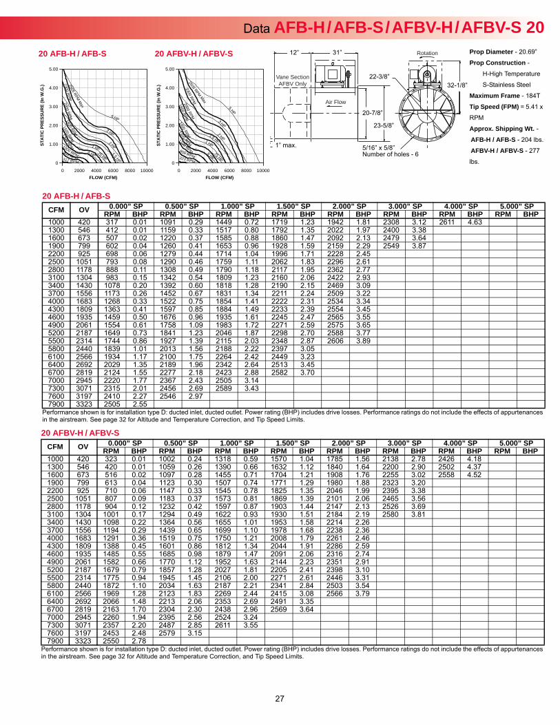
27
Data AFB-H / AFB-S / AFBV-H / AFBV-S 20Prop Diameter - 20.69”
Prop Construction -
H-High Temperature
S-Stainless Steel
Maximum Frame - 184T
Tip Speed (FPM) = 5.41 x
RPM
Approx. Shipping Wt. -AFB-H / AFB-S - 204 lbs.
AFBV-H / AFBV-S - 277
lbs.
Rotation
Air Flow
Vane SectionAFBV Only
31”
20-7/8”
23-5/8”
22-3/8”32-1/8”
5/16” x 5/8” Number of holes - 6
12”
1” max.
20 AFB-H / AFB-S
Performance shown is for installation type D: ducted inlet, ducted outlet. Power rating (BHP) includes drive losses. Performance ratings do not include the effects of appurtenances in the airstream. See page 32 for Altitude and Temperature Correction, and Tip Speed Limits.
CFM OV 0.000” SP 0.500” SP 1.000” SP 1.500” SP 2.000” SP 3.000” SP 4.000” SP 5.000” SPRPM BHP RPM BHP RPM BHP RPM BHP RPM BHP RPM BHP RPM BHP RPM BHP
1000 420 317 0.01 1091 0.29 1449 0.72 1719 1.23 1942 1.81 2308 3.12 2611 4.631300 546 412 0.01 1159 0.33 1517 0.80 1792 1.35 2022 1.97 2400 3.381600 673 507 0.02 1220 0.37 1585 0.88 1860 1.47 2092 2.13 2479 3.641900 799 602 0.04 1260 0.41 1653 0.96 1928 1.59 2159 2.29 2549 3.872200 925 698 0.06 1279 0.44 1714 1.04 1996 1.71 2228 2.452500 1051 793 0.08 1290 0.46 1759 1.11 2062 1.83 2296 2.612800 1178 888 0.11 1308 0.49 1790 1.18 2117 1.95 2362 2.773100 1304 983 0.15 1342 0.54 1809 1.23 2160 2.06 2422 2.933400 1430 1078 0.20 1392 0.60 1818 1.28 2190 2.15 2469 3.093700 1556 1173 0.26 1452 0.67 1831 1.34 2211 2.24 2509 3.224000 1683 1268 0.33 1522 0.75 1854 1.41 2222 2.31 2534 3.344300 1809 1363 0.41 1597 0.85 1884 1.49 2233 2.39 2554 3.454600 1935 1459 0.50 1676 0.96 1935 1.61 2245 2.47 2565 3.554900 2061 1554 0.61 1758 1.09 1983 1.72 2271 2.59 2575 3.655200 2187 1649 0.73 1841 1.23 2046 1.87 2298 2.70 2588 3.775500 2314 1744 0.86 1927 1.39 2115 2.03 2348 2.87 2606 3.895800 2440 1839 1.01 2013 1.56 2188 2.22 2397 3.056100 2566 1934 1.17 2100 1.75 2264 2.42 2449 3.236400 2692 2029 1.35 2189 1.96 2342 2.64 2513 3.456700 2819 2124 1.55 2277 2.18 2423 2.88 2582 3.707000 2945 2220 1.77 2367 2.43 2505 3.147300 3071 2315 2.01 2456 2.69 2589 3.437600 3197 2410 2.27 2546 2.977900 3323 2505 2.55
20 AFBV-H / AFBV-S
Performance shown is for installation type D: ducted inlet, ducted outlet. Power rating (BHP) includes drive losses. Performance ratings do not include the effects of appurtenances in the airstream. See page 32 for Altitude and Temperature Correction, and Tip Speed Limits.
CFM OV 0.000” SP 0.500” SP 1.000” SP 1.500” SP 2.000” SP 3.000” SP 4.000” SP 5.000” SPRPM BHP RPM BHP RPM BHP RPM BHP RPM BHP RPM BHP RPM BHP RPM BHP
1000 420 323 0.01 1002 0.24 1318 0.59 1570 1.04 1785 1.56 2138 2.78 2426 4.181300 546 420 0.01 1059 0.26 1390 0.66 1632 1.12 1840 1.64 2200 2.90 2502 4.371600 673 516 0.02 1097 0.28 1455 0.71 1704 1.21 1908 1.76 2255 3.02 2558 4.521900 799 613 0.04 1123 0.30 1507 0.74 1771 1.29 1980 1.88 2323 3.202200 925 710 0.06 1147 0.33 1545 0.78 1825 1.35 2046 1.99 2395 3.382500 1051 807 0.09 1183 0.37 1573 0.81 1869 1.39 2101 2.06 2465 3.562800 1178 904 0.12 1232 0.42 1597 0.87 1903 1.44 2147 2.13 2526 3.693100 1304 1001 0.17 1294 0.49 1622 0.93 1930 1.51 2184 2.19 2580 3.813400 1430 1098 0.22 1364 0.56 1655 1.01 1953 1.58 2214 2.263700 1556 1194 0.29 1439 0.65 1699 1.10 1978 1.68 2238 2.364000 1683 1291 0.36 1519 0.75 1750 1.21 2008 1.79 2261 2.464300 1809 1388 0.45 1601 0.86 1812 1.34 2044 1.91 2286 2.594600 1935 1485 0.55 1685 0.98 1879 1.47 2091 2.06 2316 2.744900 2061 1582 0.66 1770 1.12 1952 1.63 2144 2.23 2351 2.915200 2187 1679 0.79 1857 1.28 2027 1.81 2205 2.41 2398 3.105500 2314 1775 0.94 1945 1.45 2106 2.00 2271 2.61 2446 3.315800 2440 1872 1.10 2034 1.63 2187 2.21 2341 2.84 2503 3.546100 2566 1969 1.28 2123 1.83 2269 2.44 2415 3.08 2566 3.796400 2692 2066 1.48 2213 2.06 2353 2.69 2491 3.356700 2819 2163 1.70 2304 2.30 2438 2.96 2569 3.647000 2945 2260 1.94 2395 2.56 2524 3.247300 3071 2357 2.20 2487 2.85 2611 3.557600 3197 2453 2.48 2579 3.157900 3323 2550 2.78
FLOW (CFM)
STAT
IC P
RES
SUR
E (In
W.G
.)
0 2000 4000 6000 8000 10000
5.00
4.00
3.00
2.00
1.00
0
2505 RPM Max
.5 HP 323 RPM
.75 HP
2300 RPM
1 HP
2000 RPM
1.5 HP
1800 RPM
2 HP
1500 RPM
3 HP
1300 RPM
5 HP
1100 RPM 800 RPM
20 AFBV-H / AFBV-S
FLOW (CFM)
STAT
IC P
RES
SUR
E (In
W.G
.)
0 2000 4000 6000 8000 10000
5.00
4.00
3.00
2.00
1.00
0
x
2505 RPM M
a
.5 HP 317 RPM
.75 HP
2300 RPM
1 HP
2000 RPM
1.5 HP
1800 RPM
2 HP
1500 RPM
3 HP 1300 RPM
5 HP
1000 RPM 800 RPM
20 AFB-H / AFB-S
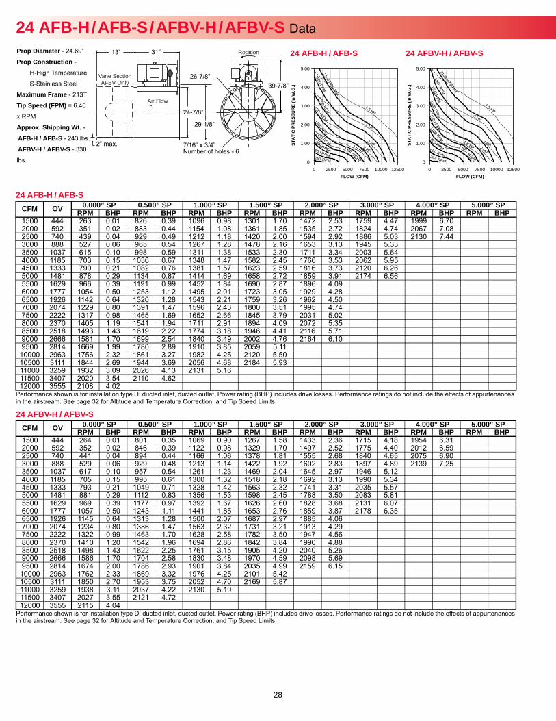
28
Prop Diameter - 24.69”
Prop Construction -
H-High Temperature
S-Stainless Steel
Maximum Frame - 213T
Tip Speed (FPM) = 6.46
x RPM
Approx. Shipping Wt. -AFB-H / AFB-S - 243 lbs.
AFBV-H / AFBV-S - 330
lbs.
24 AFB-H / AFB-S / AFBV-H / AFBV-S Data Rotation
Air Flow
Vane SectionAFBV Only
31”
24-7/8”
29-1/8”
26-7/8”39-7/8”
7/16” x 3/4”Number of holes - 6
13”
2” max.
24 AFB-H / AFB-S
Performance shown is for installation type D: ducted inlet, ducted outlet. Power rating (BHP) includes drive losses. Performance ratings do not include the effects of appurtenances in the airstream. See page 32 for Altitude and Temperature Correction, and Tip Speed Limits.
CFM OV 0.000” SP 0.500” SP 1.000” SP 1.500” SP 2.000” SP 3.000” SP 4.000” SP 5.000” SPRPM BHP RPM BHP RPM BHP RPM BHP RPM BHP RPM BHP RPM BHP RPM BHP
1500 444 263 0.01 826 0.39 1096 0.98 1301 1.70 1472 2.53 1759 4.47 1999 6.702000 592 351 0.02 883 0.44 1154 1.08 1361 1.85 1535 2.72 1824 4.74 2067 7.082500 740 439 0.04 929 0.49 1212 1.18 1420 2.00 1594 2.92 1886 5.03 2130 7.443000 888 527 0.06 965 0.54 1267 1.28 1478 2.16 1653 3.13 1945 5.333500 1037 615 0.10 998 0.59 1311 1.38 1533 2.30 1711 3.34 2003 5.644000 1185 703 0.15 1036 0.67 1348 1.47 1582 2.45 1766 3.53 2062 5.954500 1333 790 0.21 1082 0.76 1381 1.57 1623 2.59 1816 3.73 2120 6.265000 1481 878 0.29 1134 0.87 1414 1.69 1658 2.72 1859 3.91 2174 6.565500 1629 966 0.39 1191 0.99 1452 1.84 1690 2.87 1896 4.096000 1777 1054 0.50 1253 1.12 1495 2.01 1723 3.05 1929 4.286500 1926 1142 0.64 1320 1.28 1543 2.21 1759 3.26 1962 4.507000 2074 1229 0.80 1391 1.47 1596 2.43 1800 3.51 1995 4.747500 2222 1317 0.98 1465 1.69 1652 2.66 1845 3.79 2031 5.028000 2370 1405 1.19 1541 1.94 1711 2.91 1894 4.09 2072 5.358500 2518 1493 1.43 1619 2.22 1774 3.18 1946 4.41 2116 5.719000 2666 1581 1.70 1699 2.54 1840 3.49 2002 4.76 2164 6.109500 2814 1669 1.99 1780 2.89 1910 3.85 2059 5.11
10000 2963 1756 2.32 1861 3.27 1982 4.25 2120 5.5010500 3111 1844 2.69 1944 3.69 2056 4.68 2184 5.9311000 3259 1932 3.09 2026 4.13 2131 5.1611500 3407 2020 3.54 2110 4.6212000 3555 2108 4.02
24 AFBV-H / AFBV-S
Performance shown is for installation type D: ducted inlet, ducted outlet. Power rating (BHP) includes drive losses. Performance ratings do not include the effects of appurtenances in the airstream. See page 32 for Altitude and Temperature Correction, and Tip Speed Limits.
CFM OV 0.000” SP 0.500” SP 1.000” SP 1.500” SP 2.000” SP 3.000” SP 4.000” SP 5.000” SPRPM BHP RPM BHP RPM BHP RPM BHP RPM BHP RPM BHP RPM BHP RPM BHP
1500 444 264 0.01 801 0.35 1069 0.90 1267 1.58 1433 2.36 1715 4.18 1954 6.312000 592 352 0.02 846 0.39 1122 0.98 1329 1.70 1497 2.52 1775 4.40 2012 6.592500 740 441 0.04 894 0.44 1166 1.06 1378 1.81 1555 2.68 1840 4.65 2075 6.903000 888 529 0.06 929 0.48 1213 1.14 1422 1.92 1602 2.83 1897 4.89 2139 7.253500 1037 617 0.10 957 0.54 1261 1.23 1469 2.04 1645 2.97 1946 5.124000 1185 705 0.15 995 0.61 1300 1.32 1518 2.18 1692 3.13 1990 5.344500 1333 793 0.21 1049 0.71 1328 1.42 1563 2.32 1741 3.31 2035 5.575000 1481 881 0.29 1112 0.83 1356 1.53 1598 2.45 1788 3.50 2083 5.815500 1629 969 0.39 1177 0.97 1392 1.67 1626 2.60 1828 3.68 2131 6.076000 1777 1057 0.50 1243 1.11 1441 1.85 1653 2.76 1859 3.87 2178 6.356500 1926 1145 0.64 1313 1.28 1500 2.07 1687 2.97 1885 4.067000 2074 1234 0.80 1386 1.47 1563 2.32 1731 3.21 1913 4.297500 2222 1322 0.99 1463 1.70 1628 2.58 1782 3.50 1947 4.568000 2370 1410 1.20 1542 1.96 1694 2.86 1842 3.84 1990 4.888500 2518 1498 1.43 1622 2.25 1761 3.15 1905 4.20 2040 5.269000 2666 1586 1.70 1704 2.58 1830 3.48 1970 4.59 2098 5.699500 2814 1674 2.00 1786 2.93 1901 3.84 2035 4.99 2159 6.15
10000 2963 1762 2.33 1869 3.32 1976 4.25 2101 5.4210500 3111 1850 2.70 1953 3.75 2052 4.70 2169 5.8711000 3259 1938 3.11 2037 4.22 2130 5.1911500 3407 2027 3.55 2121 4.7212000 3555 2115 4.04
FLOW (CFM)
STAT
IC P
RES
SUR
E (In
W.G
.)
0 2500 5000 7500 10000 12500
5.00
4.00
3.00
2.00
1.00
0
2108 RPM Max
.75 HP 264 RPM
1 HP
1900 RPM
1.5 HP
1700 RPM
2 HP
1500 RPM
3 HP
1300 RPM 5 HP
1100 RPM
7.5 HP
900 RPM 650 RPM
24 AFBV-H / AFBV-S
FLOW (CFM)
STAT
IC P
RES
SUR
E (In
W.G
.)
0 2500 5000 7500 10000 12500
5.00
4.00
3.00
2.00
1.00
0
2108 RPM M
ax
.75 HP 263 RPM
1 HP
1900 RPM
1.5 HP
1700 RPM
2 HP
1500 RPM
3 HP
1300 RPM
5 HP 1100 RPM
7.5 HP
900 RPM 650 RPM
24 AFB-H / AFB-S
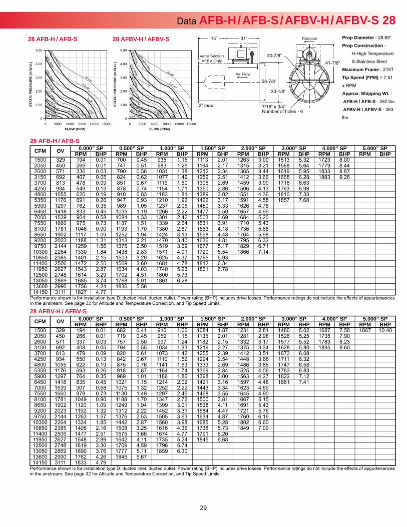
29
Data AFB-H / AFB-S / AFBV-H / AFBV-S 28Prop Diameter - 28.69”
Prop Construction -
H-High Temperature
S-Stainless Steel
Maximum Frame - 215T
Tip Speed (FPM) = 7.51
x RPM
Approx. Shipping Wt. -AFB-H / AFB-S - 282 lbs.
AFBV-H / AFBV-S - 383
lbs.
Rotation
Air Flow
Vane SectionAFBV Only
31”
28-7/8”
33-1/8”
30-7/8”41-7/8”
7/16” x 3/4”Number of holes - 6
13”
2” max.
28 AFB-H / AFB-S
Performance shown is for installation type D: ducted inlet, ducted outlet. Power rating (BHP) includes drive losses. Performance ratings do not include the effects of appurtenances in the airstream. See page 32 for Altitude and Temperature Correction, and Tip Speed Limits.
CFM OV 0.000” SP 0.500” SP 1.000” SP 1.500” SP 2.000” SP 3.000” SP 4.000” SP 5.000” SPRPM BHP RPM BHP RPM BHP RPM BHP RPM BHP RPM BHP RPM BHP RPM BHP
1500 329 194 0.01 700 0.45 935 1.15 1113 2.01 1263 3.00 1513 5.32 1723 8.002050 450 265 0.01 747 0.51 983 1.26 1164 2.17 1315 3.21 1568 5.64 1779 8.442600 571 336 0.03 790 0.56 1031 1.38 1212 2.34 1365 3.44 1619 5.95 1833 8.873150 692 407 0.05 824 0.62 1077 1.49 1259 2.51 1412 3.66 1668 6.28 1883 9.283700 813 478 0.09 851 0.67 1119 1.60 1306 2.69 1459 3.90 1716 6.634250 934 549 0.13 878 0.74 1154 1.71 1350 2.86 1506 4.13 1763 6.984800 1055 620 0.19 910 0.83 1183 1.81 1389 3.02 1551 4.36 1810 7.335350 1176 691 0.26 947 0.93 1210 1.92 1422 3.17 1591 4.58 1857 7.685900 1297 762 0.35 989 1.05 1237 2.06 1450 3.33 1626 4.786450 1418 833 0.45 1035 1.19 1266 2.22 1477 3.50 1657 4.997000 1539 904 0.58 1084 1.33 1301 2.42 1503 3.69 1684 5.207550 1660 975 0.73 1137 1.51 1339 2.64 1531 3.91 1710 5.438100 1781 1046 0.90 1193 1.70 1380 2.87 1563 4.18 1736 5.688650 1902 1117 1.09 1252 1.94 1424 3.13 1598 4.48 1764 5.989200 2023 1188 1.31 1313 2.21 1470 3.40 1636 4.81 1795 6.329750 2144 1259 1.56 1375 2.50 1519 3.69 1677 5.17 1829 6.71
10300 2264 1330 1.84 1438 2.83 1571 4.01 1720 5.54 1866 7.1410850 2385 1401 2.15 1503 3.20 1625 4.37 1765 5.9311400 2506 1472 2.50 1569 3.60 1681 4.78 1812 6.3411950 2627 1543 2.87 1634 4.03 1740 5.23 1861 6.7812500 2748 1614 3.29 1702 4.51 1800 5.7313050 2869 1685 3.74 1768 5.01 1861 6.2813600 2990 1756 4.24 1836 5.5614150 3111 1827 4.77
28 AFBV-H / AFBV-S
Performance shown is for installation type D: ducted inlet, ducted outlet. Power rating (BHP) includes drive losses. Performance ratings do not include the effects of appurtenances in the airstream. See page 32 for Altitude and Temperature Correction, and Tip Speed Limits.
CFM OV 0.000” SP 0.500” SP 1.000” SP 1.500” SP 2.000” SP 3.000” SP 4.000” SP 5.000” SPRPM BHP RPM BHP RPM BHP RPM BHP RPM BHP RPM BHP RPM BHP RPM BHP
1500 329 194 0.01 682 0.41 910 1.06 1084 1.87 1231 2.81 1480 5.02 1687 7.58 1867 10.402050 450 266 0.01 719 0.45 959 1.15 1135 2.01 1281 2.98 1526 5.25 1735 7.902600 571 337 0.03 757 0.50 997 1.24 1182 2.15 1332 3.17 1577 5.52 1783 8.233150 692 408 0.05 794 0.55 1034 1.33 1219 2.27 1375 3.34 1628 5.80 1835 8.603700 813 479 0.09 820 0.61 1073 1.42 1255 2.39 1412 3.51 1673 6.084250 934 550 0.13 842 0.67 1110 1.52 1294 2.54 1448 3.68 1711 6.324800 1055 622 0.19 875 0.76 1141 1.63 1333 2.69 1486 3.86 1747 6.585350 1176 693 0.26 918 0.87 1164 1.74 1369 2.84 1525 4.06 1783 6.835900 1297 764 0.35 969 1.01 1186 1.86 1398 3.00 1563 4.27 1822 7.126450 1418 835 0.45 1021 1.15 1214 2.02 1421 3.16 1597 4.48 1861 7.417000 1539 907 0.58 1075 1.32 1252 2.22 1443 3.34 1623 4.697550 1660 978 0.73 1130 1.49 1297 2.45 1468 3.55 1645 4.908100 1781 1049 0.90 1188 1.70 1347 2.72 1500 3.81 1667 5.158650 1902 1120 1.09 1249 1.94 1399 3.01 1538 4.11 1691 5.439200 2023 1192 1.32 1312 2.22 1452 3.31 1584 4.47 1721 5.769750 2144 1263 1.57 1376 2.53 1505 3.63 1634 4.87 1760 6.16
10300 2264 1334 1.85 1442 2.87 1560 3.98 1685 5.28 1802 6.6010850 2385 1405 2.16 1508 3.25 1616 4.35 1738 5.73 1849 7.0911400 2506 1477 2.51 1575 3.66 1674 4.77 1791 6.2011950 2627 1548 2.89 1642 4.11 1735 5.24 1845 6.6812500 2748 1619 3.30 1709 4.59 1796 5.7413050 2869 1690 3.76 1777 5.11 1859 6.3013600 2990 1762 4.26 1845 5.6714150 3111 1833 4.79
FLOW (CFM)
STAT
IC P
RES
SUR
E (In
W.G
.)
0 3000 6000 9000 12000 15000
5.00
4.00
3.00
2.00
1.00
0
1827 RPM Max
.75 HP 194 RPM
1 HP
1650 RPM
1.5 HP
1450 RPM
2 HP
1300 RPM
3 HP
1100 RPM
5 HP
900 RPM
7.5 HP
750 RPM
10 HP
550 RPM
28 AFBV-H / AFBV-S
FLOW (CFM)
STAT
IC P
RES
SUR
E (In
W.G
.)
0 3000 6000 9000 12000 15000
5.00
4.00
3.00
2.00
1.00
0
1827 RPM M
ax
.75 HP 194 RPM
1 HP
1650 RPM
1.5 HP
1450 RPM
2 HP
1300 RPM
3 HP
1100 RPM 5 HP 900 RPM
7.5 HP
750 RPM
10 HP
550 RPM
28 AFB-H / AFB-S
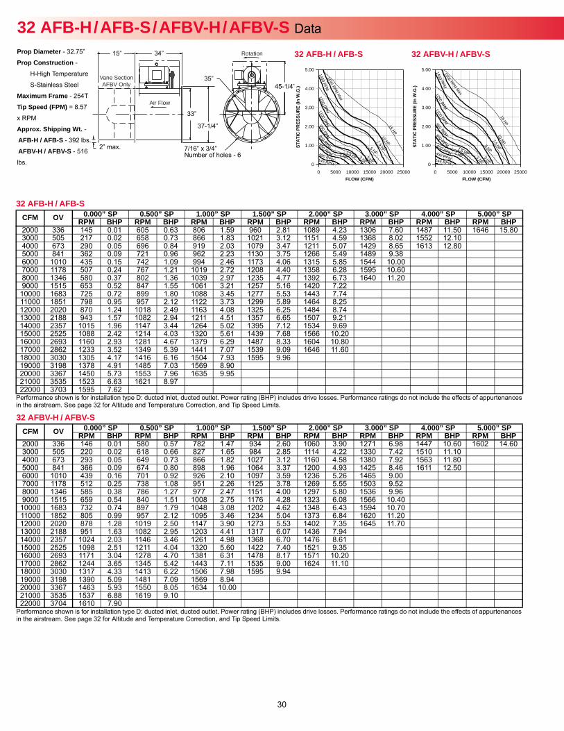
30
32 AFB-H / AFB-S / AFBV-H / AFBV-S Data Prop Diameter - 32.75”
Prop Construction -
H-High Temperature
S-Stainless Steel
Maximum Frame - 254T
Tip Speed (FPM) = 8.57
x RPM
Approx. Shipping Wt. -AFB-H / AFB-S - 392 lbs.
AFBV-H / AFBV-S - 516
lbs.
Rotation
Air Flow
Vane SectionAFBV Only
34”
33”
37-1/4”
35”45-1/4”
7/16” x 3/4”Number of holes - 6
15”
2” max.
32 AFB-H / AFB-S
Performance shown is for installation type D: ducted inlet, ducted outlet. Power rating (BHP) includes drive losses. Performance ratings do not include the effects of appurtenances in the airstream. See page 32 for Altitude and Temperature Correction, and Tip Speed Limits.
CFM OV 0.000” SP 0.500” SP 1.000” SP 1.500” SP 2.000” SP 3.000” SP 4.000” SP 5.000” SPRPM BHP RPM BHP RPM BHP RPM BHP RPM BHP RPM BHP RPM BHP RPM BHP
2000 336 145 0.01 605 0.63 806 1.59 960 2.81 1089 4.23 1306 7.60 1487 11.50 1646 15.803000 505 217 0.02 658 0.73 866 1.83 1021 3.12 1151 4.59 1368 8.02 1552 12.104000 673 290 0.05 696 0.84 919 2.03 1079 3.47 1211 5.07 1429 8.65 1613 12.805000 841 362 0.09 721 0.96 962 2.23 1130 3.75 1266 5.49 1489 9.386000 1010 435 0.15 742 1.09 994 2.46 1173 4.06 1315 5.85 1544 10.007000 1178 507 0.24 767 1.21 1019 2.72 1208 4.40 1358 6.28 1595 10.608000 1346 580 0.37 802 1.36 1039 2.97 1235 4.77 1392 6.73 1640 11.209000 1515 653 0.52 847 1.55 1061 3.21 1257 5.16 1420 7.22
10000 1683 725 0.72 899 1.80 1088 3.45 1277 5.53 1443 7.7411000 1851 798 0.95 957 2.12 1122 3.73 1299 5.89 1464 8.2512000 2020 870 1.24 1018 2.49 1163 4.08 1325 6.25 1484 8.7413000 2188 943 1.57 1082 2.94 1211 4.51 1357 6.65 1507 9.2114000 2357 1015 1.96 1147 3.44 1264 5.02 1395 7.12 1534 9.6915000 2525 1088 2.42 1214 4.03 1320 5.61 1439 7.68 1566 10.2016000 2693 1160 2.93 1281 4.67 1379 6.29 1487 8.33 1604 10.8017000 2862 1233 3.52 1349 5.39 1441 7.07 1539 9.09 1646 11.6018000 3030 1305 4.17 1416 6.16 1504 7.93 1595 9.9619000 3198 1378 4.91 1485 7.03 1569 8.9020000 3367 1450 5.73 1553 7.96 1635 9.9521000 3535 1523 6.63 1621 8.9722000 3703 1595 7.62
32 AFBV-H / AFBV-S
Performance shown is for installation type D: ducted inlet, ducted outlet. Power rating (BHP) includes drive losses. Performance ratings do not include the effects of appurtenances in the airstream. See page 32 for Altitude and Temperature Correction, and Tip Speed Limits.
CFM OV 0.000” SP 0.500” SP 1.000” SP 1.500” SP 2.000” SP 3.000” SP 4.000” SP 5.000” SPRPM BHP RPM BHP RPM BHP RPM BHP RPM BHP RPM BHP RPM BHP RPM BHP
2000 336 146 0.01 580 0.57 782 1.47 934 2.60 1060 3.90 1271 6.98 1447 10.60 1602 14.603000 505 220 0.02 618 0.66 827 1.65 984 2.85 1114 4.22 1330 7.42 1510 11.104000 673 293 0.05 649 0.73 866 1.82 1027 3.12 1160 4.58 1380 7.92 1563 11.805000 841 366 0.09 674 0.80 898 1.96 1064 3.37 1200 4.93 1425 8.46 1611 12.506000 1010 439 0.16 701 0.92 926 2.10 1097 3.59 1236 5.26 1465 9.007000 1178 512 0.25 738 1.08 951 2.26 1125 3.78 1269 5.55 1503 9.528000 1346 585 0.38 786 1.27 977 2.47 1151 4.00 1297 5.80 1536 9.969000 1515 659 0.54 840 1.51 1008 2.75 1176 4.28 1323 6.08 1566 10.40
10000 1683 732 0.74 897 1.79 1048 3.08 1202 4.62 1348 6.43 1594 10.7011000 1852 805 0.99 957 2.12 1095 3.46 1234 5.04 1373 6.84 1620 11.2012000 2020 878 1.28 1019 2.50 1147 3.90 1273 5.53 1402 7.35 1645 11.7013000 2188 951 1.63 1082 2.95 1203 4.41 1317 6.07 1436 7.9414000 2357 1024 2.03 1146 3.46 1261 4.98 1368 6.70 1476 8.6115000 2525 1098 2.51 1211 4.04 1320 5.60 1422 7.40 1521 9.3516000 2693 1171 3.04 1278 4.70 1381 6.31 1478 8.17 1571 10.2017000 2862 1244 3.65 1345 5.42 1443 7.11 1535 9.00 1624 11.1018000 3030 1317 4.33 1413 6.22 1506 7.98 1595 9.9419000 3198 1390 5.09 1481 7.09 1569 8.9420000 3367 1463 5.93 1550 8.05 1634 10.0021000 3535 1537 6.88 1619 9.1022000 3704 1610 7.90
FLOW (CFM)
STAT
IC P
RES
SUR
E (In
W.G
.)
0 5000 10000 15000 20000 25000
5.00
4.00
3.00
2.00
1.00
0
1595 RPM Max
1 HP 146 RPM
1.5 HP
1450 RPM
2 HP
1250 RPM
3 HP
1100 RPM
5 HP
950 RPM
7.5 HP
800 RPM
10 HP
650 RPM
15 HP
450 RPM
32 AFBV-H / AFBV-S
FLOW (CFM)
STAT
IC P
RES
SUR
E (In
W.G
.)
0 5000 10000 15000 20000 25000
5.00
4.00
3.00
2.00
1.00
0
1595 RPM M
ax
1 HP 145 RPM
1.5 HP
1450 RPM
2 HP
1250 RPM
3 HP
1100 RPM
5 HP
950 RPM
7.5 HP
800 RPM
10 HP 650 RPM
15 HP
450 RPM
32 AFB-H / AFB-S
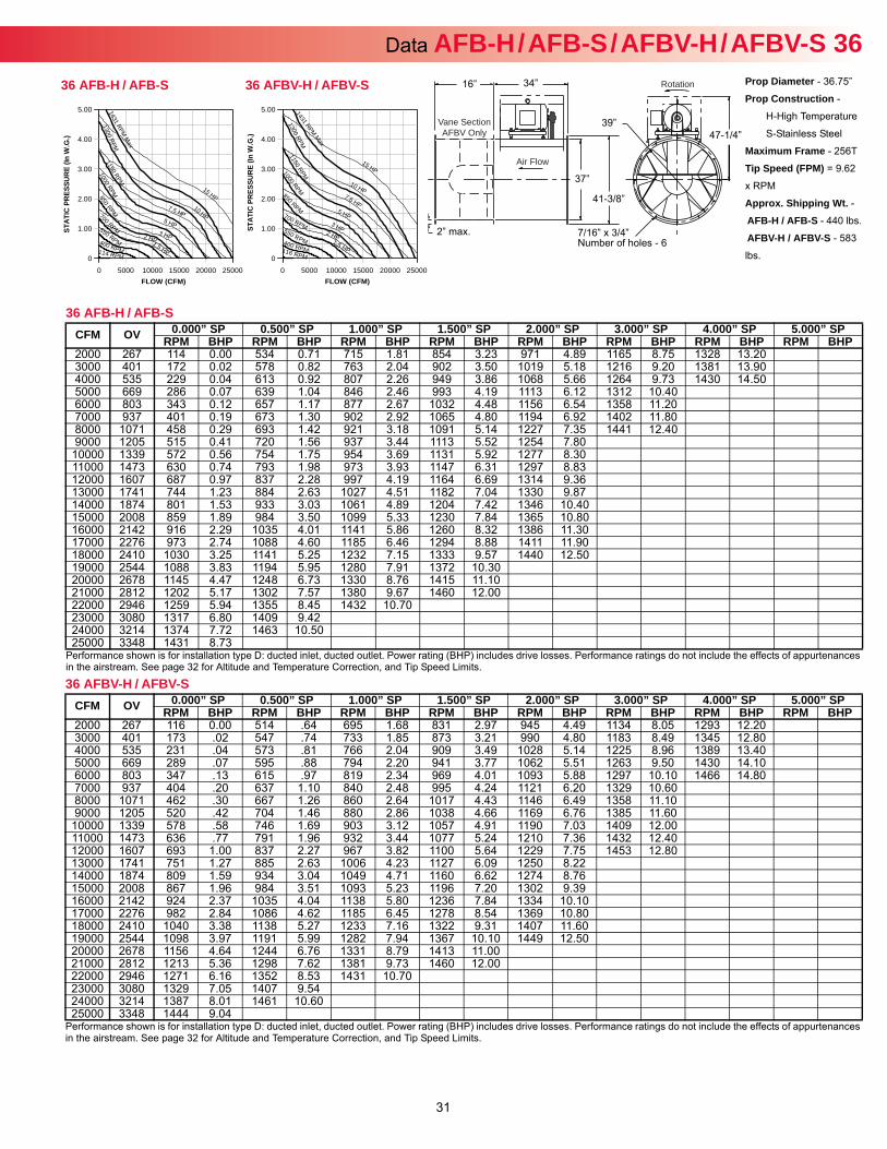
31
Data AFB-H / AFB-S / AFBV-H / AFBV-S 36Rotation
Air Flow
Vane SectionAFBV Only
34”
37”
41-3/8”
39”47-1/4”
7/16” x 3/4”Number of holes - 6
16”
2” max.
Prop Diameter - 36.75”
Prop Construction -
H-High Temperature
S-Stainless Steel
Maximum Frame - 256T
Tip Speed (FPM) = 9.62
x RPM
Approx. Shipping Wt. -AFB-H / AFB-S - 440 lbs.
AFBV-H / AFBV-S - 583
lbs.
36 AFB-H / AFB-S
Performance shown is for installation type D: ducted inlet, ducted outlet. Power rating (BHP) includes drive losses. Performance ratings do not include the effects of appurtenances in the airstream. See page 32 for Altitude and Temperature Correction, and Tip Speed Limits.
CFM OV 0.000” SP 0.500” SP 1.000” SP 1.500” SP 2.000” SP 3.000” SP 4.000” SP 5.000” SPRPM BHP RPM BHP RPM BHP RPM BHP RPM BHP RPM BHP RPM BHP RPM BHP
2000 267 114 0.00 534 0.71 715 1.81 854 3.23 971 4.89 1165 8.75 1328 13.203000 401 172 0.02 578 0.82 763 2.04 902 3.50 1019 5.18 1216 9.20 1381 13.904000 535 229 0.04 613 0.92 807 2.26 949 3.86 1068 5.66 1264 9.73 1430 14.505000 669 286 0.07 639 1.04 846 2.46 993 4.19 1113 6.12 1312 10.406000 803 343 0.12 657 1.17 877 2.67 1032 4.48 1156 6.54 1358 11.207000 937 401 0.19 673 1.30 902 2.92 1065 4.80 1194 6.92 1402 11.808000 1071 458 0.29 693 1.42 921 3.18 1091 5.14 1227 7.35 1441 12.409000 1205 515 0.41 720 1.56 937 3.44 1113 5.52 1254 7.80
10000 1339 572 0.56 754 1.75 954 3.69 1131 5.92 1277 8.3011000 1473 630 0.74 793 1.98 973 3.93 1147 6.31 1297 8.8312000 1607 687 0.97 837 2.28 997 4.19 1164 6.69 1314 9.3613000 1741 744 1.23 884 2.63 1027 4.51 1182 7.04 1330 9.8714000 1874 801 1.53 933 3.03 1061 4.89 1204 7.42 1346 10.4015000 2008 859 1.89 984 3.50 1099 5.33 1230 7.84 1365 10.8016000 2142 916 2.29 1035 4.01 1141 5.86 1260 8.32 1386 11.3017000 2276 973 2.74 1088 4.60 1185 6.46 1294 8.88 1411 11.9018000 2410 1030 3.25 1141 5.25 1232 7.15 1333 9.57 1440 12.5019000 2544 1088 3.83 1194 5.95 1280 7.91 1372 10.3020000 2678 1145 4.47 1248 6.73 1330 8.76 1415 11.1021000 2812 1202 5.17 1302 7.57 1380 9.67 1460 12.0022000 2946 1259 5.94 1355 8.45 1432 10.7023000 3080 1317 6.80 1409 9.4224000 3214 1374 7.72 1463 10.5025000 3348 1431 8.73
36 AFBV-H / AFBV-S
Performance shown is for installation type D: ducted inlet, ducted outlet. Power rating (BHP) includes drive losses. Performance ratings do not include the effects of appurtenances in the airstream. See page 32 for Altitude and Temperature Correction, and Tip Speed Limits.
CFM OV 0.000” SP 0.500” SP 1.000” SP 1.500” SP 2.000” SP 3.000” SP 4.000” SP 5.000” SPRPM BHP RPM BHP RPM BHP RPM BHP RPM BHP RPM BHP RPM BHP RPM BHP
2000 267 116 0.00 514 .64 695 1.68 831 2.97 945 4.49 1134 8.05 1293 12.203000 401 173 .02 547 .74 733 1.85 873 3.21 990 4.80 1183 8.49 1345 12.804000 535 231 .04 573 .81 766 2.04 909 3.49 1028 5.14 1225 8.96 1389 13.405000 669 289 .07 595 .88 794 2.20 941 3.77 1062 5.51 1263 9.50 1430 14.106000 803 347 .13 615 .97 819 2.34 969 4.01 1093 5.88 1297 10.10 1466 14.807000 937 404 .20 637 1.10 840 2.48 995 4.24 1121 6.20 1329 10.608000 1071 462 .30 667 1.26 860 2.64 1017 4.43 1146 6.49 1358 11.109000 1205 520 .42 704 1.46 880 2.86 1038 4.66 1169 6.76 1385 11.60
10000 1339 578 .58 746 1.69 903 3.12 1057 4.91 1190 7.03 1409 12.0011000 1473 636 .77 791 1.96 932 3.44 1077 5.24 1210 7.36 1432 12.4012000 1607 693 1.00 837 2.27 967 3.82 1100 5.64 1229 7.75 1453 12.8013000 1741 751 1.27 885 2.63 1006 4.23 1127 6.09 1250 8.2214000 1874 809 1.59 934 3.04 1049 4.71 1160 6.62 1274 8.7615000 2008 867 1.96 984 3.51 1093 5.23 1196 7.20 1302 9.3916000 2142 924 2.37 1035 4.04 1138 5.80 1236 7.84 1334 10.1017000 2276 982 2.84 1086 4.62 1185 6.45 1278 8.54 1369 10.8018000 2410 1040 3.38 1138 5.27 1233 7.16 1322 9.31 1407 11.6019000 2544 1098 3.97 1191 5.99 1282 7.94 1367 10.10 1449 12.5020000 2678 1156 4.64 1244 6.76 1331 8.79 1413 11.0021000 2812 1213 5.36 1298 7.62 1381 9.73 1460 12.0022000 2946 1271 6.16 1352 8.53 1431 10.7023000 3080 1329 7.05 1407 9.5424000 3214 1387 8.01 1461 10.6025000 3348 1444 9.04
FLOW (CFM)
STAT
IC P
RES
SUR
E (In
W.G
.)
0 5000 10000 15000 20000 25000
5.00
4.00
3.00
2.00
1.00
0
1431 RPM Max
1.5 HP 116 RPM
2 HP
1300 RPM
3 HP
1150 RPM
5 HP
1000 RPM
7.5 HP
850 RPM
10 HP
700 RPM
15 HP
550 RPM 400 RPM
36 AFBV-H / AFBV-S
FLOW (CFM)
STAT
IC P
RES
SUR
E (In
W.G
.)
0 5000 10000 15000 20000 25000
5.00
4.00
3.00
2.00
1.00
0
1431 RPM M
ax
1.5 HP 114 RPM
2 HP
1300 RPM
3 HP
1150 RPM
5 HP
1000 RPM
7.5 HP
850 RPM
10 HP 700 RPM
15 HP
550 RPM 400 RPM
36 AFB-H / AFB-S
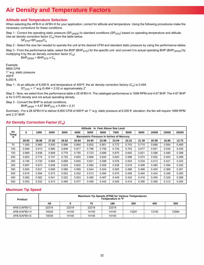
32
Air Density and Temperature Factors
When selecting the AFB-H or AFBV-H for your application, correct for altitude and temperature. Using the following procedures make the necessary corrections for these conditions.
Step 1 - Correct the operating static pressure (SPOPER) to standard conditions (SPSTD) based on operating temperature and altitude. Use air density correction factor (Ca) from the table below.
SPSTD=SPOPER/Ca
Step 2 - Select the size fan needed to operate the unit at the desired CFM and standard static pressure by using the performance tables.
Step 3 - From the performance table, select the BHP (BHPSTD) for the specific unit and convert it to actual operating BHP (BHPOPER) by multiplying it by the air density correction factor (Ca).
BHPOPER = BHPSTD x Ca
Example8800 CFM1” w.g. static pressure400oF6,000 ft.
Step 1 - At an altitude of 6,000 ft. and temperature of 400oF, the air density correction factory (Ca) is 0.494.STSTD = 1” w.g./0.494 = 2.02 or approximately 2”
Step 2 - Now, we select from the performance table a 28 AFBV-H. The cataloged performance is 1699 RPM and 4.67 BHP. The 4.67 BHP is for 0.075 density and not actual operating density.
Step 3 - Convert the BHP to actual conditions.BHPOPER = 4.67 BHPSTD x 0.494 = 2.31
Summary - For a 28 AFBV-H to deliver 8,800 CFM of 400oF air 1” w.g. static pressure at 6,000 ft. elevation, the fan will require 1699 RPM and 2.31 BHP.
Altitude and Temperature Selection
AirTemp
°F
Altitude in Feet Above Sea Level0 1000 2000 3000 4000 5000 6000 7000 8000 9000 10000 15000 20000
Barometric Pressure in Inches of Mercury29.92 28.86 27.82 26.82 25.84 24.90 23.98 23.09 22.22 21.39 20.58 16.89 13.75
70 1.000 0.965 0.930 0.896 0.864 0.832 0.801 0.772 0.743 0.715 0.688 0.564 0.460100 0.946 0.913 0.880 0.848 0.817 0.788 0.758 0.730 0.703 0.677 0.651 0.534 0.435150 0.869 0.838 0.808 0.779 0.750 0.723 0.696 0.670 0.645 0.621 0.598 0.490 0.399200 0.803 0.774 0.747 0.720 0.693 0.668 0.644 0.620 0.596 0.574 0.552 0.453 0.369250 0.746 0.720 0.694 0.669 0.645 0.621 0.598 0.576 0.554 0.534 0.513 0.421 0.343300 0.697 0.673 0.648 0.625 0.602 0.580 0.559 0.538 0.518 0.498 0.480 0.394 0.320350 0.654 0.631 0.608 0.586 0.565 0.544 0.524 0.505 0.486 0.468 0.450 0.369 0.301400 0.616 0.594 0.573 0.552 0.532 0.513 0.494 0.475 0.458 0.440 0.424 0.348 0.283450 0.582 0.562 0.541 0.522 0.503 0.485 0.467 0.449 0.432 0.416 0.400 0.329 0.268500 0.552 0.532 0.513 0.495 0.477 0.459 0.442 0.426 0.410 0.395 0.380 0.312 0.254
Air Density Correction Factor (Ca)
ProductMaximum Tip Speeds (FPM) for Various Temperatures
Temperature in oF
-50 0 70 180 350 400 500AFB-C/AFBV-C 22219 22219 22219 22219 - - -AFB-H/AFBV-H 10039 14140 14140 14140 13291 13150 12584AFB-S/AFBV-S 10039 14140 14140 14140 - - -
Maximum Tip Speed

AF - June 2016B50032-001