Embed Size (px)
Citation preview
Worcester Controls
MODELS20 – For AF-17 Boards Mounted Inside 10-23 75 Actuator.
30 – For AF-17 Boards Mounted Inside 25-30 75 Actuator.
AF-17-1K, 120A or 240A, 1000 ohm Resistance Input
AF-17-13, 120A or 240A, 135 ohm Resistance Input
AF-17-1, 120A or 240A, 1 to 5 Milliamp Input
AF-17-4, 120A or 240A, 4 to 20 Milliamp Input
AF-17-10, 120A or 240A, 10 to 50 Milliamp Input
AF-17-5V, 120A or 240A, 0 to 5 VDC Input
AF-17-XV, 120A or 240A, 0 to 10 VDC Input
R – Reverse Action Option
120A-120 VAC Power Circuits
240A-240 VAC Power Circuits
WCAIM2031
AF-17 Electronic PositionerInstallation, Operation and Maintenance Instructions
2 AF-17 Electronic Positioner: Installation, Operation and Maintenance WCAIM2031
1.0 GENERAL 31.1 Basic Design 31.2 Environmental Considerations 4
1.2.1 Temperature 41.2.2 Positioner Temperature 41.2.3 Humidity 41.2.4 Input Circuit Noise Protection 4
2.0 ELECTRONIC CIRCUIT BOARD 62.1 General 62.2 Circuit Board Configurations 62.3 LED Indicators 62.4 Controls 6
2.4.1 Range 62.4.2 Zero 62.4.3 A-H 6
2.5 AC Power Control 6
3.0 INSTALLATION OF AF-17 INTO 3.0 SERIES 75 ELECTRIC ACTUATOR 7
3.1 General 73.1.1 Check Kit for Parts 73.1.2 Tools Needed 83.1.3 Operation Check of Basic Actuator 8
3.2 Mounting Potentiometer 83.2.1 Mounting Single Potentiometer Into
Series 75 Electric Actuator 83.2.2 Mounting Dual Potentiometer Into
Series 75 Electric Actuator 83.2.3 Potentiometer Wiring 83.2.4 Adjusting Potentiometer 93.2.5 Important Note 9
3.3 Mounting Circuit Board 113.3.1 For 120/240 VAC 10-23 Size Electric Actuators 113.3.2 For 120/240 VAC 25 and 30 Size Electric Actuators 123.3.3 For Optional 4-20 mA Position Output Installation 12
3.4 Wiring AF-17 Board to Actuator 133.4.1 Terminal Strip 133.4.2 Feedback Connections 143.4.3 Output Connections 143.4.4 For 10-30 AF-17 240 VAC Positioner Wiring 143.4.5 Wiring for AF-17 with 4-20 mA Position Output 14
3.5 Actuator Power 153.5.1 Wire Size 153.5.2 Terminations and Voltage 153.5.3 Minimum Fuse Ratings 15
3.6 Input Signal Connections 163.6.1 Milliampere 153.6.2 Resistive 163.6.3 Direct 17
4.0 CALIBRATION AND ADJUSTMENT 174.1 Initial Setup and Adjustment 174.2 Zero Adjustment 174.3 Range Adjustment 174.4 AH Adjustment 174.5 Adjustment Recheck 184.6 Operational Check 18
4.6.1 Increasing Signal 184.6.2 Decreasing Signal 184.6.3 Attaching Label 18
4.7 If Problems Occur 184.7.1 Cam Adjustment 184.7.2 Feedback Pot Calibration 184.7.3 Reverse Acting 184.7.4 Adjustment to Loop Process 184.7.5 Check Fuse F1 194.7.6 Check Basic Actuator for Proper Operation 194.7.7 Check for Noise Problems 194.7.8 Replace Circuit Board 19
5.0 OPERATIONAL VARIABLES 195.1 Sensitivity 195.2 Reduced Travel Operation 195.3 Split Range 195.4 Reverse Action 19
5.4.1 Milliampere Input 205.4.2 Resistive Input 205.4.3 Voltage Input 205.4.4 240 VAC 20
6.0 TECHNICAL DATA 206.1 AC Input Voltage 206.2 Input Circuit Specs 206.3 Output Circuit Specs 216.4 Input Circuit Characteristics 21
6.4.1 Input Circuit Load Resistances 216.4.2 Nominal Useable Input Signal Deadband 21
6.5 Controls 21
7.0 APPLICATION NOTES 227.1 DC Motor Actuator 227.2 Bypass Switch for Manual Control 22
8.0 TROUBLESHOOTING 238.1 General 238.2 Symptom Table 248.3 Troubleshooting Guidelines 25
9.0 SUGGESTED SPARES 27
Flow Control Division
Worcester Controls
TABLE OF CONTENTS
WCAIM2031 AF-17 Electronic Positioner: Installation, Operation and Maintenance 3
1.0 GENERAL
1.1 Basic DesignThe Worcester AF-17 Electronic Positioner was designed for use with the Worcester Series 75 actuators. However, it may also beused with other actuators or electrically operated rotary devices, provided the specified load parameters as given in Part 6.3 arenot exceeded.
CAUTION: This positioner is sensitive to electrical noise; please see part 1.2.
PLEASE READ THIS SECTION
A. The AC AF-17 board 4-20 mA signal input circuit is protected with a 62 mA fuse (F1). The fuse is used to protect the inputcircuit from an excessively high voltage. The fuse used in the input circuit is a Littlefuse PICO II very fast-acting fuse rated at 62mA. There is a spare fuse located on the circuit board in the area of the large power resistors.
B. The AF-17 board is designed to receive a floating current input signal. This allows several pieces of equipment to be operatedfrom the same current loop while at the same time remaining electrically independent of each other.
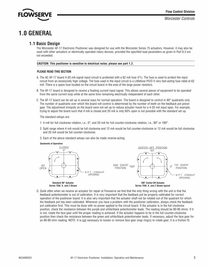
C. The AF-17 board can be set up in several ways for normal operation. The board is designed to control in 90° quadrants only.The number of quadrants over which the board will control is determined by the number of teeth on the feedback pot piniongear. The adjustment trimpots on the board were not set up to reduce actuator travel for a 4-20 mA input span. For example,trying to adjust the board such that 4 mA is closed and 20 mA is only 60% open is not possible with the standard set up.
The standard setups are:
1. 4 mA for full clockwise rotation, i.e., 0°, and 20 mA for full counter-clockwise rotation, i.e., 90° or 180°.
2. Split range where 4 mA would be full clockwise and 12 mA would be full counter-clockwise or 12 mA would be full clockwiseand 20 mA would be full counter-clockwise.
3. Each of the above standard setups can also be made reverse-acting.
Standard 90° Actuator 180° Center-Off ActuatorSeries 75W, X, and Z Shown Series 75W, X, and Z Shown typical
D. Quite often when we receive an actuator for repair at Flowserve we find that the only thing wrong with the unit is that thefeedback potentiometer is out of calibration. It is very important that the feedback pot be properly calibrated for correctoperation of the positioner board. It is also very important that the actuator shaft not be rotated out of the quadrant for whichthe feedback pot has been calibrated. Whenever you have a problem with the positioner calibration, always check the feedbackpot calibration first. This must be done with no power applied to the circuit board. If the actuator is in the full clockwiseposition, check the resistance between the purple and white/black potentiometer leads. The reading should be 80-90 ohms. If itis not, rotate the face gear until the proper reading is achieved. If the actuator happens to be in the full counter-clockwiseposition then check the resistance between the green and white/black potentiometer leads. If necessary, adjust the face gear foran 80-90 ohm reading. NOTE: It is not necessary to loosen or remove face gear snap ring(s) to rotate gear; it is a friction fit.
Flow Control Division
Worcester Controls
Quadrants of Operation
4 AF-17 Electronic Positioner: Installation, Operation and Maintenance WCAIM2031
1.2 Environmental ConsiderationsCAUTION: The AF-17 Electronic Positioner is sensitive to electrical noise on signal or supply lines and in the environment.For maximum sensitivity, the electrical noise level should not exceed 10mV. Follow installation, calibration and adjustmentguidelines carefully and use shielded wire as stated in paragraph 1.2.4.
Flowserve recommends that all products that must be stored prior to installation be stored indoors, in an environmentsuitable for human occupancy. Do not store product in areas where exposure to relative humidity above 85%, acid or alkalifumes, radiation above normal background, ultraviolet light, or temperatures above 120°F or below 40°F may occur. Do notstore within 50 feet of any source of ozone.
Temperature and humidity are the two most important factors that determine the usefulness and life of electronic equipment.
1.2.1 TemperatureOperating solid-state electronic equipment near or beyond its high temperature ratings is the primary cause for mostfailures. It is, therefore, very important that the user be aware of and take into consideration, factors that affect thetemperature at which the electronic circuits will operate.
Operating an electronic device at or below its low temperature rating generally results in a unit operating poorly or not at all,but it will usually resume normal operation as soon as rated operating temperatures are reached. Low temperatureproblems can be easily cured by addition of a thermostatically controlled heater to the unit’s housing.
At high temperatures, some components will destruct completely when their maximum temperature is exceeded; others willcease operation at temperatures above ratings and will return to operation at normal ratings, but may have beenpermanently changed in one or another parameter, causing a device to operate poorly, and may also cause greatly reducedcomponent life.
1.2.2 Positioner Temperature ConsiderationsThe Worcester AF-17 Electronic Positioner is rated for operation between -40°F and 160°F. When using the positioner insidethe Worcester 75 Series actuators, a maximum ambient temperature of 115°F is required to ensure the circuit boardmaximum temperature of 160°F is not exceeded.
1.2.3 HumidityMost electronic equipment has a reasonable degree of inherent humidity protection and additional protection is supplied bythe manufacturer, in the form of moisture proofing and fungicidal coatings.
Such protection, and the 3 to 4 watts of heat generated by the circuit board assembly will generally suffice for environmentswhere the average relative humidity is in the area of 80% or less and ambient temperatures are in the order of 70°F averagewith only occasional short term exposure to temperatures up to 90°F. Where relative humidity is consistently 80 to 90% andthe ambient temperature is high or subject to large variations, consideration should be given to installing a heater andthermostat option in the enclosure. The heater should not increase the enclosure temperature to the point where the circuitboard assembly’s temperature rating of 160°F is exceeded.
In those instances where the internal heater would bring the circuit board’s operating temperature near or above itsmaximum rating, the user might consider purging the enclosure with a cool, dry gas. The initial costs can usually be paidoff quickly in the form of greatly extended equipment life, low maintenance needs, and much less process downtime.
1.2.4 Input Circuit Noise ProtectionShielded wiring should be used for all signal input circuit wiring regardless of length.
With separately housed positioners, the wiring from the feedback potentiometer to remote positioner, would be consideredas signal input wiring and should also be shielded wire.
The shields should never be used in place of one of the input wires, and the shields normally should be grounded toequipment housings at one end of the wiring run only. Grounding both ends of shielding can eliminate the shielding benefitsbecause of current ground loops. If two or more shielded cables come to the positioner from different locations, ground theshields at the positioner.
Flow Control Division
Worcester Controls
WCAIM2031 AF-17 Electronic Positioner: Installation, Operation and Maintenance 5
Flow Control Division
Worcester Controls
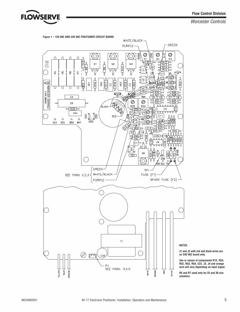
Figure 1 – 120 VAC AND 240 VAC POSITIONER CIRCUIT BOARD
NOTES:
J1 and J2 with red and black wires areon 240 VAC board only.
Use or values of components R13, R24,R52, R53, R54, C22, J3, J4 and orangewire will vary depending on input signal.
R5 and R7 used only for 25 and 30 sizeactuators.
6 AF-17 Electronic Positioner: Installation, Operation and Maintenance WCAIM2031
2.0 ELECTRONIC CIRCUIT BOARD (120/240 VAC)
2.1 GeneralFigure 1 defines the location of major components and wires from the positioner to terminal strip connections. The #18 gaugewhite wire is the AC power unit “neutral” (or common) in the case of DC input wire. The #20 gauge white/black wire is one of theconnections between the feedback pot and the terminal block (TB-1) on the circuit board.
2.2 Circuit Board ConfigurationsThe positioner board is factory supplied for one of the seven input signal options.
NOTE: Field changes to the positioner board are not advised. Consult Flowserve before attempting any modification.
2.3 LED IndicatorsLight emitting diodes (LED) marked LD1, LD2 and LD3 are in the output circuits of amplifier U4. LD1 is tied to pin #13, LD2 to pin#14, and LD3 to pin #1, and they are each associated with their respective opto-coupler U1, U2 and U3 and indicate when theinput side of the opto-coupler is energized.
2.4 ControlsThree adjustment potentiometers are provided, located on the top side of the board and marked “Range”, “Zero”, and “AH”. SeeFigure 1.
2.4.1 RangeThe “Range” Control adjusts the positioner’s feedback circuit to cover the same span of voltage as generated by the inputsignal.
2.4.2 ZeroThe “Zero” adjustment is basically an offset adjustment in that essentially all input signals start at other than a zero signalcondition, i.e., 1, 4 or 12 milliamps.
2.4.3 A-HThe “AH” Control is used primarily to balance the positioner to the dynamic characteristics of the device and media beingcontrolled. Functionally, it varies the amount of input signal that must be applied to the positioner to cause the actuator toreverse its direction of rotation. In effect it varies the deadband of the positioner on a reversing signal condition only. Thedeadband — the percent change in input signal change that must be applied to initiate a movement of the actuator — on asignal that is constantly increasing or decreasing, is relatively unaffected by the “AH” control.
The “AH” control can vary the balance point deadband from approximately .3% to 4.0% of signal span. It can therefore beused to help decrease the effects of signal noise, with a tradeoff in accuracy/sensitivity.
2.5 AC Power ControlThe AC output circuits are controlled by solid-state switches (triacs Q1, Q2, Q3), which will provide trouble-free operation for thelife of the equipment they are used with, AS LONG AS THEY ARE OPERATED WITHIN THEIR RATINGS.
The ratings for the solid-state switches used in the Worcester AF-17 Positioner are listed in Part 6.3.
Flow Control Division
Worcester Controls
WCAIM2031 AF-17 Electronic Positioner: Installation, Operation and Maintenance 7
3.0 INSTALLATION OF AF-17 INTO SERIES 75 ELECTRIC ACTUATOR
3.1 GeneralIf the actuator was purchased with the AF-17 positioner board factory installed, proceed to section 4.0.
If a 4-20 mA Position Output option is also used with the AF-17 positioner, refer to paragraph 3.3.3 for installation (if not alreadyinstalled), and paragraph 3.4.5 for wiring.
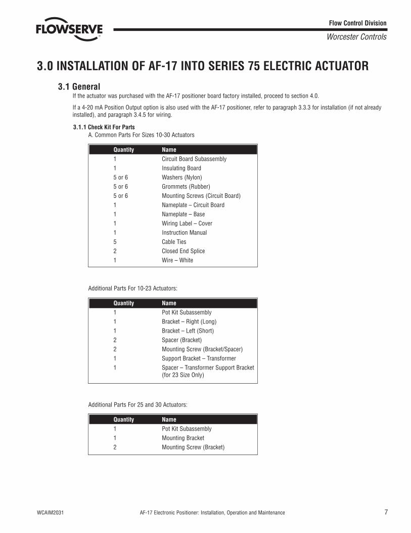
3.1.1 Check Kit For PartsA. Common Parts For Sizes 10-30 Actuators
Additional Parts For 10-23 Actuators:
Additional Parts For 25 and 30 Actuators:
Quantity Name1 Pot Kit Subassembly1 Mounting Bracket2 Mounting Screw (Bracket)
Quantity Name1 Pot Kit Subassembly1 Bracket – Right (Long)1 Bracket – Left (Short)2 Spacer (Bracket)2 Mounting Screw (Bracket/Spacer)1 Support Bracket – Transformer1 Spacer – Transformer Support Bracket
(for 23 Size Only)
Quantity Name1 Circuit Board Subassembly1 Insulating Board5 or 6 Washers (Nylon)5 or 6 Grommets (Rubber)5 or 6 Mounting Screws (Circuit Board)1 Nameplate – Circuit Board 1 Nameplate – Base1 Wiring Label – Cover1 Instruction Manual5 Cable Ties2 Closed End Splice1 Wire – White
Flow Control Division
Worcester Controls
8 AF-17 Electronic Positioner: Installation, Operation and Maintenance WCAIM2031
3.1.2. Tools Needed1/4" nut driver, 1/8" screwdriver, needle nose pliers, 1/16" Allen wrench (cams and spur gear).
Volt/ohm meter (checking feedback potentiometer resistance, voltages – incoming process signal).
Milliamp source (to check calibration of positioner on actuator).
VAC line cord (to power basic actuator).
3.1.3. Operation Check of Basic ActuatorSet cams for about 1° to 3° of over travel in each direction (full open and full closed). That is, for 0° to 90° operation setat minus 3° and plus 93°. Power terminals 1 and 3 for CCW rotation, terminals 1 and 4 for CW rotation (referenceparagraph 4.7.6.).
3.2 Mounting Potentiometer3.2.1 Mounting Single Potentiometer Into Series 75 Actuator
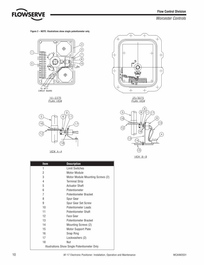
See Figure 2.A. With the potentiometer mounted to the potentiometer bracket and the spur gear loosely fitted to the potentiometer shaft,
mount the potentiometer bracket (if not already mounted) as follows:
10-23 75 Actuator:Remove the motor module mounting screws on the side of the module furthest away from the actuator shaft. Positionpotentiometer assembly bracket holes over screw holes and line up potentiometer shaft with center of actuator shaft,replace and tighten screws.
25/3075 Actuator:Attach potentiometer bracket to motor support plate between the terminal strip and actuator shaft with mounting screwsas shown.
3.2.2 Mounting Dual Potentiometer Into Series 75 Electric ActuatorA dual potentiometer is also available and is required with the AF-17 when external resistance indication is also desired, orwhen the 4-20 Position Output option is also used.
Each potentiometer can serve only one function. Remote resistance monitoring and an AF-17, for instance, cannot share apotentiometer.
Note: Voltage limit of “B” potentiometer is 30 volts maximum.
Mount potentiometer per paragraph A of 3.2.1.
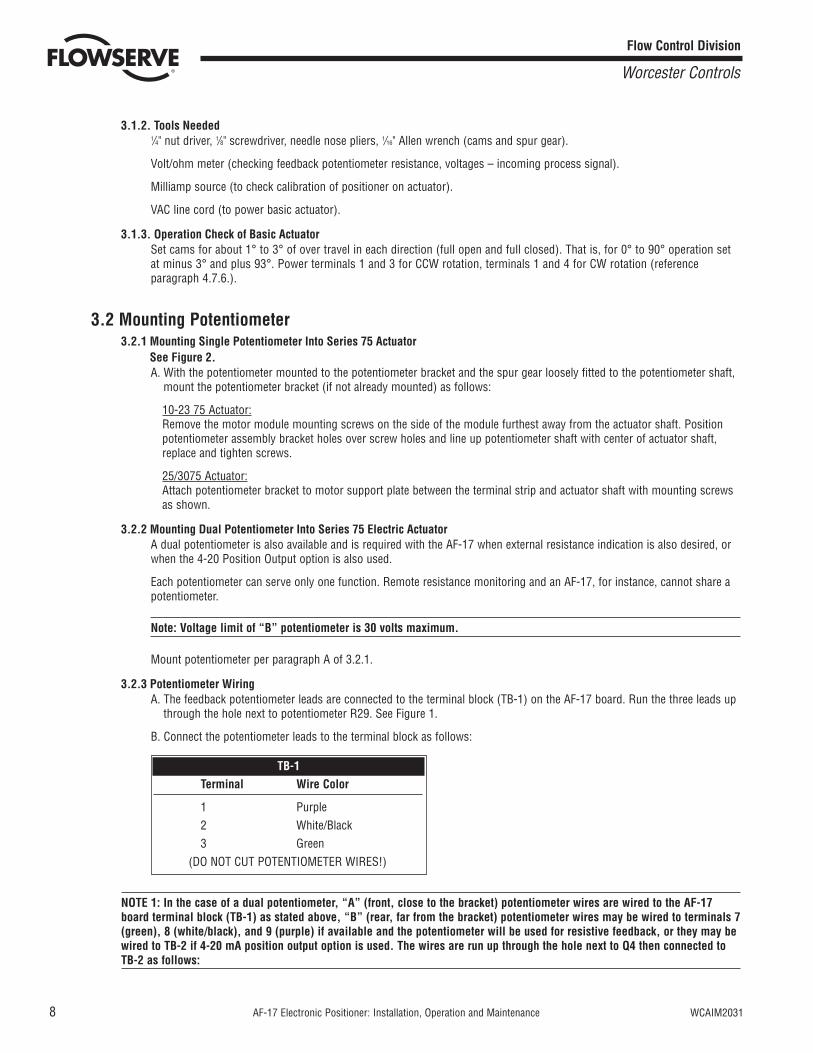
3.2.3 Potentiometer WiringA. The feedback potentiometer leads are connected to the terminal block (TB-1) on the AF-17 board. Run the three leads up
through the hole next to potentiometer R29. See Figure 1.
B. Connect the potentiometer leads to the terminal block as follows:
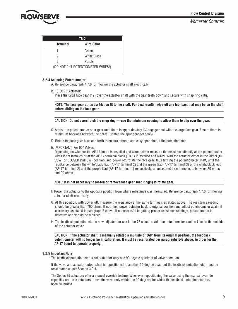
NOTE 1: In the case of a dual potentiometer, “A” (front, close to the bracket) potentiometer wires are wired to the AF-17board terminal block (TB-1) as stated above, “B” (rear, far from the bracket) potentiometer wires may be wired to terminals 7(green), 8 (white/black), and 9 (purple) if available and the potentiometer will be used for resistive feedback, or they may bewired to TB-2 if 4-20 mA position output option is used. The wires are run up through the hole next to Q4 then connected toTB-2 as follows:
TB-1Terminal Wire Color
1 Purple2 White/Black3 Green
(DO NOT CUT POTENTIOMETER WIRES!)
Flow Control Division
Worcester Controls
WCAIM2031 AF-17 Electronic Positioner: Installation, Operation and Maintenance 9
3.2.4 Adjusting PotentiometerA. Reference paragraph 4.7.6 for moving the actuator shaft electrically.
B. 10-30 75 Actuator:Place the large face gear (12) over the actuator shaft with the gear teeth down and secure with snap ring (16).
NOTE: The face gear utilizes a friction fit to the shaft. For best results, wipe off any lubricant that may be on the shaftbefore sliding on the face gear.
CAUTION: Do not overstretch the snap ring — use the minimum opening to allow them to slip over the gear.
C. Adjust the potentiometer spur gear until there is approximately 1/16" engagement with the large face gear. Ensure there isminimum backlash between the gears. Tighten the spur gear set screw.
D. Rotate the face gear back and forth to ensure smooth and easy operation of the potentiometer.
E. IMPORTANT: For 90° Valves:Depending on whether the AF-17 board is installed and wired, either measure the resistance directly at the potentiometerwires if not installed or at the AF-17 terminal block (TB-1) if installed and wired. With the actuator either in the OPEN (fullCCW) or CLOSED (full CW) position, and power off, rotate the face gear, thus turning the potentiometer shaft, until theresistance between the white/black lead (AF-17 terminal 2) and the green lead (AF-17 terminal 3) or the white/black lead(AF-17 terminal 2) and the purple lead (AF-17 terminal 1) respectively, as measured by ohmmeter, is between 80 ohmsand 90 ohms.
NOTE: It is not necessary to loosen or remove face gear snap ring(s) to rotate gear.
F. Power the actuator to the opposite position from where resistance was measured. Reference paragraph 4.7.6 for movingactuator shaft electrically.
G. At this position, with power off, measure the resistance at the same terminals as stated above. The resistance readingshould be greater than 700 ohms. If not, then power actuator back to original position and adjust potentiometer again, ifnecessary, as stated in paragraph E above. If unsuccessful in getting proper resistance readings, potentiometer isdefective and should be replaced.
H. The feedback potentiometer is now adjusted for use in the 75 actuator. Add the potentiometer caution label to the outsideof the actuator cover.
CAUTION: If the actuator shaft is manually rotated a multiple of 360° from its original position, the feedbackpotentiometer will no longer be in calibration. It must be recalibrated per paragraphs E-G above, in order for the AF-17 board to operate properly.
3.2.5 Important NoteThe feedback potentiometer is calibrated for only one 90-degree quadrant of valve operation.
If the valve and actuator output shaft is repositioned to another 90-degree quadrant the feedback potentiometer must berecalibrated as per Section 3.2.4.
The Series 75 actuators offer a manual override feature. Whenever repositioning the valve using the manual overridecapability on these actuators, move the valve only within the 90 degrees for which the feedback potentiometer has been calibrated.
TB-2Terminal Wire Color
1 Green2 White/Black3 Purple
(DO NOT CUT POTENTIOMETER WIRES!)
Flow Control Division
Worcester Controls
10 AF-17 Electronic Positioner: Installation, Operation and Maintenance WCAIM2031
Flow Control Division
Worcester Controls
Figure 2 – NOTE: Illustrations show single potentiometer only.
Item Description1 Limit Switches2 Motor Module3 Motor Module Mounting Screws (2)4 Terminal Strip5 Actuator Shaft6 Potentiometer7 Potentiometer Bracket8 Spur Gear9 Spur Gear Set Screw10 Potentiometer Leads11 Potentiometer Shaft12 Face Gear13 Potentiometer Bracket14 Mounting Screws (2)15 Motor Support Plate16 Snap Ring17 Lockwashers (2)18 Nut
Illustrations Show Single Potentiometer Only
WCAIM2031 AF-17 Electronic Positioner: Installation, Operation and Maintenance 11
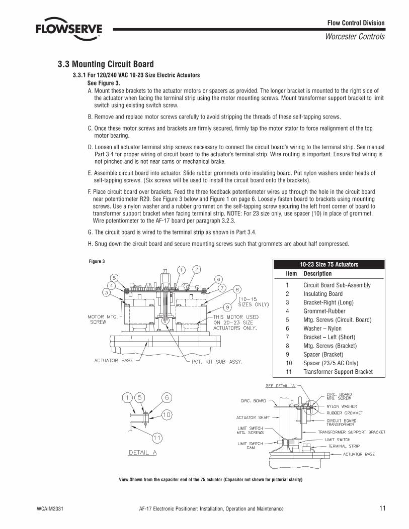
3.3 Mounting Circuit Board3.3.1 For 120/240 VAC 10-23 Size Electric Actuators
See Figure 3.A. Mount these brackets to the actuator motors or spacers as provided. The longer bracket is mounted to the right side of
the actuator when facing the terminal strip using the motor mounting screws. Mount transformer support bracket to limitswitch using existing switch screw.
B. Remove and replace motor screws carefully to avoid stripping the threads of these self-tapping screws.
C. Once these motor screws and brackets are firmly secured, firmly tap the motor stator to force realignment of the topmotor bearing.
D. Loosen all actuator terminal strip screws necessary to connect the circuit board’s wiring to the terminal strip. See manualPart 3.4 for proper wiring of circuit board to the actuator’s terminal strip. Wire routing is important. Ensure that wiring isnot pinched and is not near cams or mechanical brake.
E. Assemble circuit board into actuator. Slide rubber grommets onto insulating board. Put nylon washers under heads ofself-tapping screws. (Six screws will be used to install the circuit board onto the brackets).
F. Place circuit board over brackets. Feed the three feedback potentiometer wires up through the hole in the circuit boardnear potentiometer R29. See Figure 3 below and Figure 1 on page 6. Loosely fasten board to brackets using mountingscrews. Use a nylon washer and a rubber grommet on the self-tapping screw securing the left front corner of board totransformer support bracket when facing terminal strip. NOTE: For 23 size only, use spacer (10) in place of grommet.Wire potentiometer to the AF-17 board per paragraph 3.2.3.
G. The circuit board is wired to the terminal strip as shown in Part 3.4.
H. Snug down the circuit board and secure mounting screws such that grommets are about half compressed.
View Shown from the capacitor end of the 75 actuator (Capacitor not shown for pictorial clarity)
Flow Control Division
Worcester Controls
Figure 3 10-23 Size 75 ActuatorsItem Description
1 Circuit Board Sub-Assembly2 Insulating Board3 Bracket-Right (Long)4 Grommet-Rubber5 Mtg. Screws (Circuit. Board)6 Washer – Nylon7 Bracket – Left (Short)8 Mtg. Screws (Bracket)9 Spacer (Bracket)10 Spacer (2375 AC Only)11 Transformer Support Bracket
12 AF-17 Electronic Positioner: Installation, Operation and Maintenance WCAIM2031
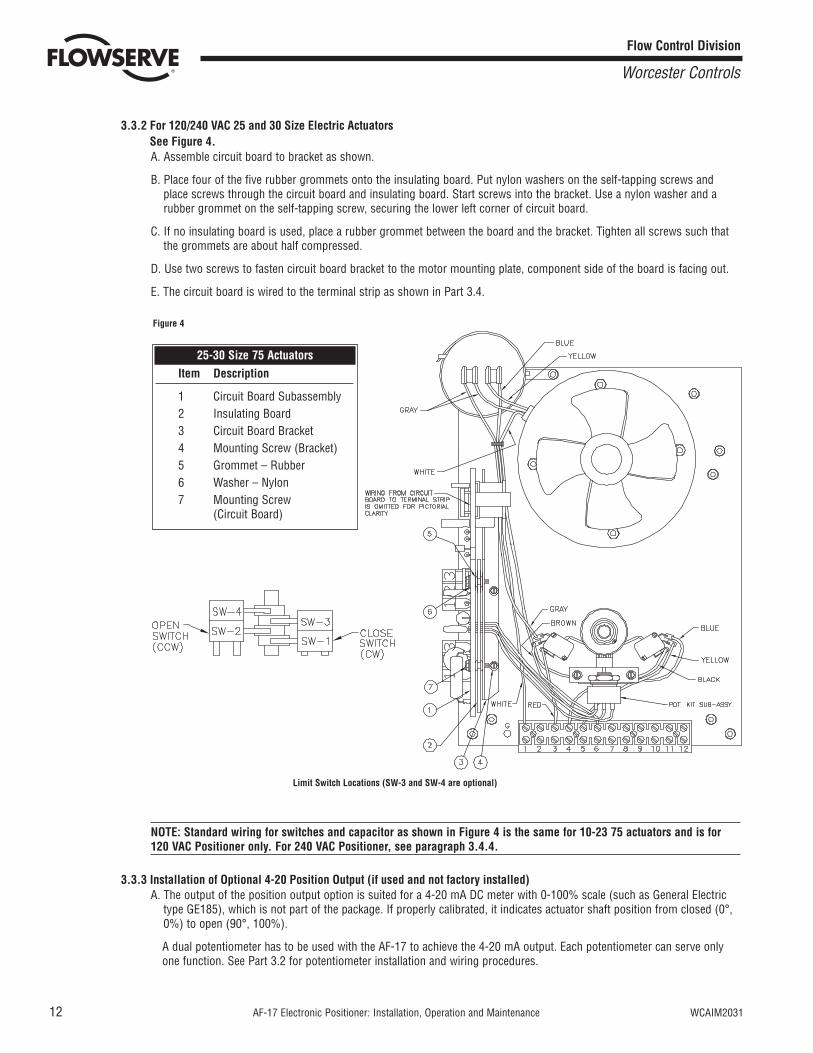
3.3.2 For 120/240 VAC 25 and 30 Size Electric ActuatorsSee Figure 4.A. Assemble circuit board to bracket as shown.
B. Place four of the five rubber grommets onto the insulating board. Put nylon washers on the self-tapping screws andplace screws through the circuit board and insulating board. Start screws into the bracket. Use a nylon washer and arubber grommet on the self-tapping screw, securing the lower left corner of circuit board.
C. If no insulating board is used, place a rubber grommet between the board and the bracket. Tighten all screws such thatthe grommets are about half compressed.
D. Use two screws to fasten circuit board bracket to the motor mounting plate, component side of the board is facing out.
E. The circuit board is wired to the terminal strip as shown in Part 3.4.
Limit Switch Locations (SW-3 and SW-4 are optional)
NOTE: Standard wiring for switches and capacitor as shown in Figure 4 is the same for 10-23 75 actuators and is for120 VAC Positioner only. For 240 VAC Positioner, see paragraph 3.4.4.
3.3.3 Installation of Optional 4-20 Position Output (if used and not factory installed)A. The output of the position output option is suited for a 4-20 mA DC meter with 0-100% scale (such as General Electric
type GE185), which is not part of the package. If properly calibrated, it indicates actuator shaft position from closed (0°,0%) to open (90°, 100%).
A dual potentiometer has to be used with the AF-17 to achieve the 4-20 mA output. Each potentiometer can serve onlyone function. See Part 3.2 for potentiometer installation and wiring procedures.
Flow Control Division
Worcester Controls
Figure 4
25-30 Size 75 ActuatorsItem Description
1 Circuit Board Subassembly2 Insulating Board3 Circuit Board Bracket4 Mounting Screw (Bracket)5 Grommet – Rubber6 Washer – Nylon7 Mounting Screw
(Circuit Board)
WCAIM2031 AF-17 Electronic Positioner: Installation, Operation and Maintenance 13
B. Parts Available for Assembly
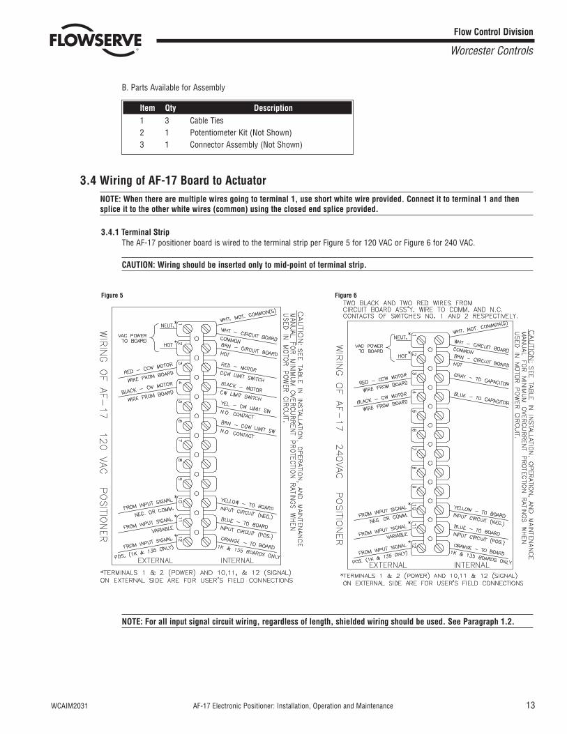
3.4 Wiring of AF-17 Board to ActuatorNOTE: When there are multiple wires going to terminal 1, use short white wire provided. Connect it to terminal 1 and thensplice it to the other white wires (common) using the closed end splice provided.
3.4.1 Terminal StripThe AF-17 positioner board is wired to the terminal strip per Figure 5 for 120 VAC or Figure 6 for 240 VAC.
CAUTION: Wiring should be inserted only to mid-point of terminal strip.
NOTE: For all input signal circuit wiring, regardless of length, shielded wiring should be used. See Paragraph 1.2.
Item Qty Description1 3 Cable Ties2 1 Potentiometer Kit (Not Shown)3 1 Connector Assembly (Not Shown)
Flow Control Division
Worcester Controls
Figure 5 Figure 6
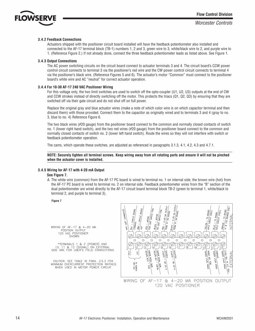
Figure 7
14 AF-17 Electronic Positioner: Installation, Operation and Maintenance WCAIM2031
3.4.2 Feedback ConnectionsActuators shipped with the positioner circuit board installed will have the feedback potentiometer also installed andconnected to the AF-17 terminal block (TB-1) numbers 1, 2 and 3, green wire to 3, white/black wire to 2, and purple wire to1. (Reference Figure 2.) If not already done, connect the three feedback potentiometer leads as listed above. See Figure 1.
3.4.3 Output ConnectionsThe AC power switching circuits on the circuit board connect to actuator terminals 3 and 4. The circuit board’s CCW powercontrol circuit connects to terminal 3 via the positioner’s red wire and the CW power control circuit connects to terminal 4via the positioner’s black wire. (Reference Figures 5 and 6). The actuator’s motor “Common” must connect to the positionerboard’s white wire and AC “neutral” for correct actuator operation.
3.4.4 For 10-30 AF-17 240 VAC Positioner WiringFor this voltage only, the two limit switches are used to switch off the opto-coupler (U1, U2, U3) outputs at the end of CWand CCW strokes instead of directly switching off the motor. This protects the triacs (Q1, Q2, Q3) by ensuring that they areswitched off via their gate circuit and do not shut off on full power.
Replace the original gray and blue actuator wires (make a note of which color wire is on which capacitor terminal and thendiscard them) with those provided. Connect them to the capacitor as originally wired and to terminals 3 and 4 (gray to no.3, blue to no. 4) Reference Figure 6.
The two black wires (#20 gauge) from the positioner board connect to the common and normally closed contacts of switchno. 1 (lower right hand switch), and the two red wires (#20 gauge) from the positioner board connect to the common andnormally closed contacts of switch no. 2 (lower left hand switch). Route the wires so they will not interfere with switch orfeedback potentiometer operation.
The cams, which operate these switches, are adjusted as referenced in paragraphs 3.1.3, 4.1, 4.2, 4.3 and 4.7.1.
NOTE: Securely tighten all terminal screws. Keep wiring away from all rotating parts and ensure it will not be pinchedwhen the actuator cover is installed.
3.4.5 Wiring for AF-17 with 4-20 mA Output See Figure 7.A. The white wire (common) from the AF-17 PC board is wired to terminal no. 1 on internal side; the brown wire (hot) from
the AF-17 PC board is wired to terminal no. 2 on internal side. Feedback potentiometer wires from the “B” section of thedual potentiometer are wired directly to the AF-17 circuit board terminal block TB-2 (green to terminal 1, white/black toterminal 2, and purple to terminal 3).
Flow Control Division
Worcester Controls
WCAIM2031 AF-17 Electronic Positioner: Installation, Operation and Maintenance 15
B. For 120 VAC board only, remove yellow wire from terminal 5 and brown wire from terminal 6, disconnect them from N.O.contacts of switches 1 and 2 and discard them. For all AC boards, connect wires of output signal connector assemblyfrom AF-17 board connector (P1) such that red wire (+) is wired to terminal 5 and black wire (-) is wired to terminal 6 oninternal side of terminal strip.
NOTE: Check for wiring diagram label inside of cover, if it doesn’t have the 4-20 mA output option wiring shown,mark label for terminals 5 and 6 according to Figure 7.
C. External wiring is between actuator terminal strip and outside power supply and various controls. Common wire of thepower supply is wired to terminal 1 and hot wire of the power supply to terminal 2. An outside position indicator meter iswired with positive connection to terminal 5 and negative connection to terminal 6.
D. Securely tighten all terminal screws. Secure all wires neatly with the cable ties. Keep wiring away from all rotating partsand ensure wiring is not pinched when actuator cover is installed.
E. The feedback potentiometer has to be adjusted to obtain the proper resistance range. See paragraph 3.2.4. To obtainproper 4-20 mA output, the AF-17 board 4-20 mA output has to be calibrated. Using an ammeter connected to actuatorterminals 5 (positive) and 6 (negative) adjust the two potentiometers R29 and R30 on the board. Locate the actuator inthe closed position (0%) and adjust R30 potentiometer (closest to TB-2) to obtain 4 mA on the ammeter. Move theactuator to the open position (100%) and adjust R29 potentiometer (closest to the shaft hole) to obtain 20 mA. Becauseadjustment of one potentiometer affects the other, repeat the procedure several times to obtain proper values.
IMPORTANT: The feedback potentiometer is calibrated for only one 90° quadrant of valve operation. If the output shaft isrepositioned to another 90° quadrant or if the output shaft is rotated a multiple of 360° from its original position, or if the4-20 mA position output option is disconnected from the AF-17 board, the feedback potentiometer will no longer be incalibration and must be recalibrated. See paragraph C of part 1.1 and paragraph 3.2.4.
3.5 Actuator Power3.5.1 Wire Size
AC power to the positioner and from the positioner to the actuator should be with wire no smaller than #18 gauge and withinsulation rated for the particular application. The #18 gauge wire size is sufficient for all Worcester Series 75 actuators.When using the positioner with other makes of actuators, check the manufacturer’s current rating to determine the correctwire size.
3.5.2 Terminations and VoltageAC power connections are made to terminals 1 and 2 of the terminal strip. The AC neutral, or common, wire should beconnected to terminal #1 and the AC “Hot” wire to terminal #2. Note that the positioner requires a minimum of 110 VAC,and a maximum of 130 VAC for the 120 VAC version and a 220 VAC minimum, 250 VAC maximum for the 240 VAC version.
Grounding wires should be connected to green colored grounding screw (if present) on actuator base or to any base platemounting screw in the actuator.
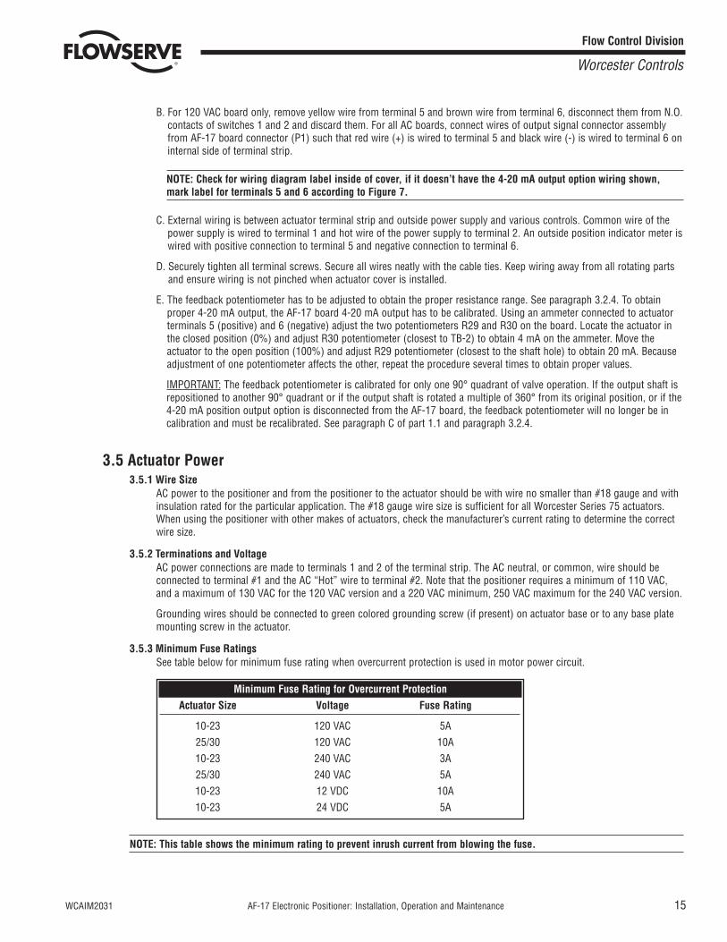
3.5.3 Minimum Fuse RatingsSee table below for minimum fuse rating when overcurrent protection is used in motor power circuit.
NOTE: This table shows the minimum rating to prevent inrush current from blowing the fuse.
Minimum Fuse Rating for Overcurrent ProtectionActuator Size Voltage Fuse Rating
10-23 120 VAC 5A25/30 120 VAC 10A10-23 240 VAC 3A25/30 240 VAC 5A10-23 12 VDC 10A10-23 24 VDC 5A
Flow Control Division
Worcester Controls
3.6 Input Signal ConnectionsNOTE: The 120/240 VAC AF-17 positioner board signal input circuit is protected by a 1/16 amp fuse, F1. See Figure 1 andParagraph A of Part 1.1.
3.6.1 AF-17-1, AF-17-4, AF-17-10 (Milliamp Input Signal for AF-17)For a milliampe signal input, the more positive or “High” signal lead should connect to terminal 11. The less positive or“Common” lead should connect to terminal 10. Terminal 10 is (-), Terminal 11 is (+).
This positioner is available for use with the standard milliamp signals: 1 to 5, 4 to 20, and 10 to 50 milliamps. Thepositioner board is factory calibrated for one of the three milliamp signal ranges, and field changes are not advised. A labelon the circuit board indicates the positioner’s signal range.
Paragraph 6.4.1 gives the nominal resistance load, which the positioner presents to the control circuit for the three signal ranges.
Comparison of resistance measurements made at terminals 10 and 11 (on the yellow and blue wires from the circuit board)against the resistances shown in paragraph 6.4.1 provides a quick way to determine the milliamp range for which aparticular board is calibrated.
NOTE: If the circuit board has an orange wire (See Figure 1) attached to it, the board is for a Resistive Input. SeeParagraph 3.6.2 and Figure 8.
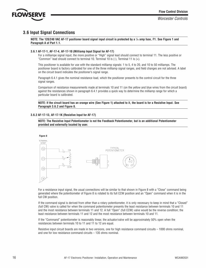
3.6.2 AF-17-13, AF-17-1K (Resistive Input for AF-17)
NOTE: The Resistive Input Potentiometer is not the Feedback Potentiometer, but is an additional Potentiometerprovided and externally located by user.
For a resistance input signal, the usual connections will be similar to that shown in Figure 8 with a “Close” command beinggenerated where the potentiometer of Figure 8 is rotated to its full CCW position and an “Open” command when it is in thefull CW position.
If the command signal is derived from other than a rotary potentiometer, it is only necessary to keep in mind that a “Closed”(full CW) valve is called for when the command potentiometer presents the least resistance between terminals 10 and 11and the most resistance between terminals 11 and 12. A full “Open” (full CCW) valve would be the reverse condition; theleast resistance between terminals 11 and 12 and the most resistance between terminals 10 and 11.
If the “Command” potentiometer is reasonably linear, the actuator/valve will be approximately 50% open when theresistances between terminals 10 to 11 and 11 to 12 are equal.
Resistive input circuit boards are made in two versions, one for high resistance command circuits – 1000 ohms nominal,and one for low resistance command circuits – 135 ohms nominal.
Figure 8
16 AF-17 Electronic Positioner: Installation, Operation and Maintenance WCAIM2031
Flow Control Division
Worcester Controls
WCAIM2031 AF-17 Electronic Positioner: Installation, Operation and Maintenance 17
3.6.3 AF-17-5V, AF-17-XV (Direct Voltage Input Signal for AF-17)For a voltage input signal, the more positive or “High” signal lead should connect to terminal 11. The less positive or“Common” lead should connect to terminal 10. Terminal 10 is (-), Terminal 11 is (+).
This positioner is available for use with the standard direct voltage signals: 0 to 5 VDC and 0 to 10 VDC. The positionerboard is factory calibrated for one of these two signal ranges and field changes are not advised.
Paragraph 6.4.1 gives the nominal resistance load that the positioner presents to the control circuit for the two signal ranges.
4.0 CALIBRATION AND ADJUSTMENT
4.1 Initial Set-Up and Adjustment (Applies To All Models)When properly adjusted, the actuator will stop at the full open and full closed points as a result of having reached one of the limitsof the input signal span, and the actuator’s limit switches will be used in a back-up mode to stop the actuator, should an out-of-range input signal occur.
In case of Series 75, 240 VAC Actuator with AF-17 240 VAC positioner, the two limit switches do not limit actuator travel. Exercisecaution not to override limit switches. Reference paragraph 3.4.4.
Actuators with factory-mounted positioners will be shipped with their limit switches properly adjusted. When the positioner,whether internally or externally mounted, is installed to an actuator in the field, the actuator limit switches should be initiallyadjusted to trip at 1 to 3 degrees AFTER the positioner would normally have shut the actuator off upon reaching the upper orlower input signal limit. Reference parts 4.2, 4.3 and paragraph 4.7.1. CAUTION: If either the valve or the actuator have mechanicalend of travel stops, the limit switches should be set to trip JUST before a mechanical stop is reached even if this point iscoincident with one of the limits of the input signal.
NOTE: Prior to starting potentiometer adjustment procedure set the AF-17 adjustment potentiometers as follows: “Range”and “Zero” potentiometers full clockwise, “AH” full clockwise then 1/4 turn counter-clockwise.
4.2 “Zero” Adjustment [“Zero” Potentiometer Initially Full Clockwise (CW)]Apply a “full closed” signal to the positioners input, i.e., 4 mA. The actuator should rotate in the CW direction and come to a stopat or near the CW limit of rotation. Adjust the “Zero” adjustment until the actuator stops in the fully closed position AND theindicator LD2 is “OFF”. If LD2 is “ON”, this indicates that the “Closed” (SW-1) limit switch has tripped. The “Closed” limit switchshould be adjusted such that it will trip 1° to 3° beyond the full closed position of the actuator. Readjust the “Closed” limit switchif necessary.
4.3 “Range” Adjustment [“Range” Potentiometer Initially Full Clockwise (CW)]Apply a “full open” signal to the positioners input, i.e., 20 mA. The actuator should rotate in the CCW direction and come to a stopat or near the CCW limit of rotation. Adjust the “Range” adjustment until the actuator stops in the fully open position AND theindicator LD1 is “OFF”. If LD1 is “ON”, this indicates that the “Open” (SW-2) limit switch has tripped. The “Open” limit switchshould be adjusted such that it will trip 1° to 3° beyond the full “Open” position of the actuator. Readjust the “Open” limit switch ifnecessary. When 4.2 and 4.3 are complete, ensure that limit switches are set 1° to 3° beyond the electronic travel limits.Reference CAUTION in 4.1.
4.4 “AH” Adjustment (Anti-Hunt) (“AH” Potentiometer – turn fully clockwise (CW), then 1/4 turn CCW)This adjustment can be made only after installation is complete and actuator is operational. Apply sufficient input signal to turn theactuator shaft an amount that would open the valve approximately 10%. If the actuator hunts, adjust the “AH” control in a CCWdirection until the hunting stops. If no hunting occurs, adjust the control towards the CW direction. Increase the input signal insteps of approximately 10% and reset the “AH” adjustment until no hunting occurs over the entire input signal range.
Flow Control Division
Worcester Controls
18 AF-17 Electronic Positioner: Installation, Operation and Maintenance WCAIM2031
4.5 Adjustment RecheckThere is some interaction between adjustments of the “Zero” and “Range” controls, therefore if an adjustment is made at one endof travel, the opposite end should be rechecked.
Although the “Range” and “Zero” settings are relatively unaffected by fairly large temperature changes, it is suggested thatpositioners be checked during a users routine maintenance schedule.
4.6 Operational CheckOnce the AF-17’s circuit board zero and span potentiometers are set for the minimum and maximum process signal values,typically a 4-20 mA signal, do the following checks:
4.6.1 Increasing SignalReduce process input signal below the minimum value so that actuator stops on its closed limit switch and closed LD2 ison. Increasing the input signal in small increments should allow the actuator to move in angular increments proportional tothese small incremental increases in the incoming signal.
4.6.2 Decreasing SignalContinually adjust the signal until the maximum signal value is reached and actuator is in fully open position. With a signalover 20 mA, when the positioner is calibrated for 4 to 20 mA, the actuator will operate until the proper cam has actuated theopen limit switch. Note that the open LD1 will be “on” when actuator stops at limit switch.
In similar fashion, decrease the process signal in small values. The actuator should move closed in small steps until thefully closed position is reached at the minimum signal value, typically 4 mA for a 4-20 mA calibration.
4.6.3 Attaching LabelAttach label to board.
4.7 If Problems OccurIf problems occur while trying to obtain the desired positioner action, check the following:
4.7.1 Cam AdjustmentThe actuator cams should actuate the limit switches 1° to 3° after the actuator stops at either the fully open or fully closedposition.
If the actuator is closed at 0 degrees, the limit switch must actuate by the time the actuator is at the minus 1 to 3 degreeposition. Similarly, at the open or 90-degree position, the limit switch must actuate by the time the actuator is at the 91 to93 degree position.
NOTE: See CAUTION in part 4.1.
4.7.2 Feedback Potentiometer CalibrationCheck the feedback potentiometer calibration per paragraph 3.2.4 of the manual. At either the full open or the full closedposition, stopping at either limit switch, the potentiometer must still be within its electrical travel. To verify this, check theresistance at either the full open or full closed position. The resistance measured between terminals 2 and 3 or 2 and 1 onthe AF-17 terminal block, with the power off, must be between 80 ohms and 90 ohms.
Readjust the feedback potentiometer as necessary and check as in the previous steps for proper incremental movement ofthe valve actuator from limit switch to limit switch; full closed to full open; -1° to -3°, +91° to +93°.
4.7.3 Reverse-ActingFor a reverse-acting actuator, read part 5.4 in the manual. Simply follow the instructions of part 5.4 and readjust the circuitboard “zero” and “range” potentiometers as needed.
4.7.4 Adjustment to Loop ProcessOnce the actuator and positioner are installed in the system, further adjustments may be necessary to trim the AF-17 circuitboard/actuator action to the process controller’s action in the process loop. The AH potentiometer on the circuit board mayrequire adjustment counterclockwise to stop the AF-17 circuitry from reacting to spurious electrical noise signals.
Flow Control Division
Worcester Controls
WCAIM2031 AF-17 Electronic Positioner: Installation, Operation and Maintenance 19
4.7.5 Check Fuse F1For AC boards, check fuse F1 to see if it is blown. If it is, replace with spare fuse F2 attached to PC Board and order anotherfuse for spare (Newark part number 94F2146). IMPORTANT: To check fuse - remove it from circuit and test with ohmmeter.Resistance should be about 6 ohms.
NOTE: If fuse F1 is blown, excessive voltage (possibly 120 VAC) was applied to the signal input circuit. If so, correctthis condition before changing fuse. See Paragraph A of Part 1.1.
For DC boards, check fuse F1 to see if it is blown. If it is, replace it with a 1!?4", 250 volt, 3 amp fuse, available throughany electrical supplier. See Part 2.2 in DCAF17 IOM supplement.
4.7.6 Check basic actuator for proper operation using the proper AC voltageA. Remove red and black leads coming from circuit board at terminals 3 and 4 (if already installed). Tape stripped ends of
these wires.
B. Alternately energize, with the appropriate AC voltage, terminals 1 and 3 and 1 and 4. The actuator should move clockwisewhen energizing terminals 1 and 4, stopping only at the clockwise limit switch. The actuator should move counter-clockwise when energizing terminals 1 and 3, stopping only at the counter-clockwise limit switch.
NOTE: For AF-17 240 VAC Positioner only, limit switches do not directly control motor. Therefore, the actuator willnot stop when the limit switches trip. Use care not to drive the actuator past its normal limits. Run the actuator to itslimits in each direction, to assure proper operation of the actuator.
4.7.7 Check for Noise ProblemsIf the circuit board’s light emitting diodes (LEDs) blink or seem to continuously glow, electrical noise is interfering with thepositioner’s input process signal. (Always use shielded cable for the process signal coming to the AF-17 board. Ground theshield at only one end.) Adjust AF-17 positioner as necessary. See Section 4.0.
4.7.8 Replace Circuit BoardIf problems still occur after taking these remedial steps, replace circuit board in the actuator.
5.0 OPERATIONAL VARIABLES
5.1 SensitivityThe Worcester AF-17 Electronic Positioner has been designed to a standard sensitivity equivalent to approximately 240 positionsfor a 15 second 90 degree shaft movement.
5.2 Reduced Travel OperationA small amount of travel reduction can be achieved (4-6 degrees). This can be accomplished by applying maximum and minimuminput signals and adjusting the “Range” and “Zero” controls to determine the new rotation end limits. (Limit switch cams shouldalso be reset. See parts 4.1 and 4.4.)
5.3 Split RangeWith AF-17 Positioner circuit board revisions (Revision R10 and later) split range adjustment capability is available with standardboard and may be obtained using the standard calibration procedures.
5.4 Reverse ActionThe usual mode of operation of an actuator is to use an increasing signal for the open direction of travel and a decreasing signalfor the close direction of travel. For use in certain types of applications, it may be desirable to operate using a decreasing signalfor the open direction and an increasing signal for the close direction. For some valves this can be done by cross-line mountingthe actuator (mounting the actuator to the valve such that it is rotated 90° from the normal mounting position. This has the effectof rotating the valve ball 90° with the actuator at its 4 mA position. As the signal is increased toward 20 mA the valve ball willtravel toward its closed position but in a counter-clockwise direction. Therefore, this method will work only with valves with roundseats, not with characterized seats). No positioner wiring changes would be required using this method. If cross-line mounting isnot feasible, the reversal can be accomplished at the positioner as follows:
Flow Control Division
Worcester Controls
20 AF-17 Electronic Positioner: Installation, Operation and Maintenance WCAIM2031
5.4.1 Input Reversing – (AF-17-1, AF-17-4, AF-17-10) (mA Input); 120 VACReverse the black and red wires from the positioner board; the red goes to terminal 4 and the black to terminal 3. Changethe feedback potentiometer wires on the board at TB-1 terminals 1 and 3; the purple wire goes to terminal 3 and the greenwire to terminal 1. The positioner will now operate in reverse of the usual manner and the controls “Range” and “Zero” willalso be reversed. The “Range” control should now be used to adjust the closed end of travel and the “Zero” control used toadjust the open end of travel. Always adjust the “Zero” control first!
NOTE: If the 4-20 mA signal output (if installed) is to be reversed also, then the wires at TB-2 terminals 1 and 3 mustalso be reversed. The AF-17 board must be recalibrated after switching the wires at TB-2 and/or TB-1.
5.4.2 Input Reversing – (AF-17-1K, AF-17-13) (Resistance Input); 120 VACMake the same changes as in 5.4.1. If the input is from a manual control station and it is desired that the direction for“Closed” and “Open” also be reversed at the “Command” potentiometer, change additionally the wires from the circuit boardto terminals 10 and 12. Connect the orange wire to terminal 10 and the yellow wire to terminal 12. The operation ofadjustments “Range” and “Zero” will be reversed, as in paragraph 5.4.1. Recalibrate the AF-17 board.
5.4.3 Input Reversing – (AF-17-5V, AF-17-XV) (Direct Voltage Input); 120 VACFollow same procedure as paragraph 5.4.1.
5.4.4 Input Reversing, 240 VAC OnlyIn addition to performing the steps in paragraphs 5.4.1, 5.4.2, or 5.4.3, it is also necessary to swap the two black wiresfrom limit switch 1 to limit switch 2 and the two red wires from limit switch 2 to limit switch 1.
6.0 TECHNICAL DATA
6.1 AC Input Voltage:All voltages ........................................................................................... ±10%
Power Consumption (Circuit Board Only).........................................2.5 watts
6.2 Input Circuit SpecificationsMaximum Noise Level at Maximum Positions............................Approx. 7mV
Resistance InputAF-17-1K.........................................................................Nominal 1000 ohmsAF-17-13 ...........................................................................Nominal 135 ohms
Current InputAF-17-1 ................................................................................ 1 to 5 milliampsAF-17-4 .............................................................................. 4 to 20 milliampsAF-17-10............................................................................10 to 50 milliamps
Voltage InputAF-17-5V........................................................................................0 to 5 VDCAF-17-XV......................................................................................0 to 10 VDC
Flow Control Division
Worcester Controls
WCAIM2031 AF-17 Electronic Positioner: Installation, Operation and Maintenance 21
6.3 Output Circuits SpecificationsAll Models
Maximum Surge Current ...............................................100 amps for 1 cycle
Maximum Normal Starting or In-Rush Current ............10 amps for 1 second
Maximum Stall Current ..................................................8 amps for 1 minute
Maximum Running Current – Resistive Load......................................5 amps90% Duty Cycle
Maximum Running Current – Inductive Load......................................3 amps90% Duty Cycle
Maximum Peak Voltage on Load Circuit ............................................800 VACAll 120 VAC and 240 VAC
4-20 mA output will drive 20 mA into a 600 ohm maximum load.
6.4 Input Circuit Characteristics6.4.1 Input Circuit Load Resistances
Approximate
1 to 5 milliamp Models .......................................................................1000 ohms
4 to 20 milliamp Models .......................................................................220 ohms
10 to 50 milliamp Models .....................................................................100 ohms
0 to 5 VDC Models................................................................................800 ohms
0 to 10 VDC Models............................................................................1100 ohms
6.4.2 Nominal Useable Input Signal Deadband1000 ohm Input .....................................................................................5.5 ohms
135 ohm Input..................................................................................... .75 ohms
1 to 5 milliamp Input.................................................................20 microamperes
4 to 20 milliamp Input...............................................................80 microamperes
10 to 50 milliamp Input...........................................................200 microamperes
0 to 5 VDC Input................................................................................25 millivolts
0 to 10 VDC Input..............................................................................50 millivolts
NOTE: Above “Useable” deadband figures are “NORMS” determined by multiple tests of various actuator/valvecombinations. All actuators used a permanent split phase motor, with an output shaft speed of 1 RPM (15-secondcycle time). Electronic braking was employed on all tests. Results may differ in applications where different shaftspeeds are used.
6.5 Controls – All ModelsZero – Adjustment for Low End of Control Signal +60% Span
Range – Adjustment for High End of Control Signal -60% Span
AH – Adjustment for Hysteresis (Anti-Hunt) 0.3% to 4.0% of full scale
4 mA – Adjust 4 mA Output
20 mA – Adjust 20 mA Output
Flow Control Division
Worcester Controls
7.0 APPLICATION NOTES
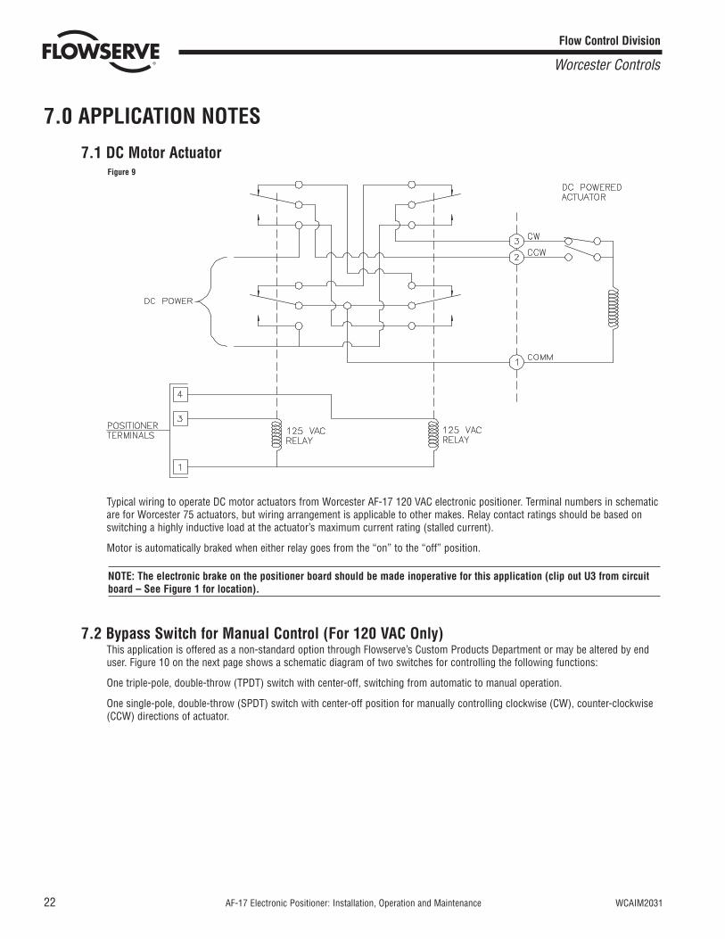
7.1 DC Motor Actuator
Typical wiring to operate DC motor actuators from Worcester AF-17 120 VAC electronic positioner. Terminal numbers in schematicare for Worcester 75 actuators, but wiring arrangement is applicable to other makes. Relay contact ratings should be based onswitching a highly inductive load at the actuator’s maximum current rating (stalled current).
Motor is automatically braked when either relay goes from the “on” to the “off” position.
NOTE: The electronic brake on the positioner board should be made inoperative for this application (clip out U3 from circuitboard – See Figure 1 for location).
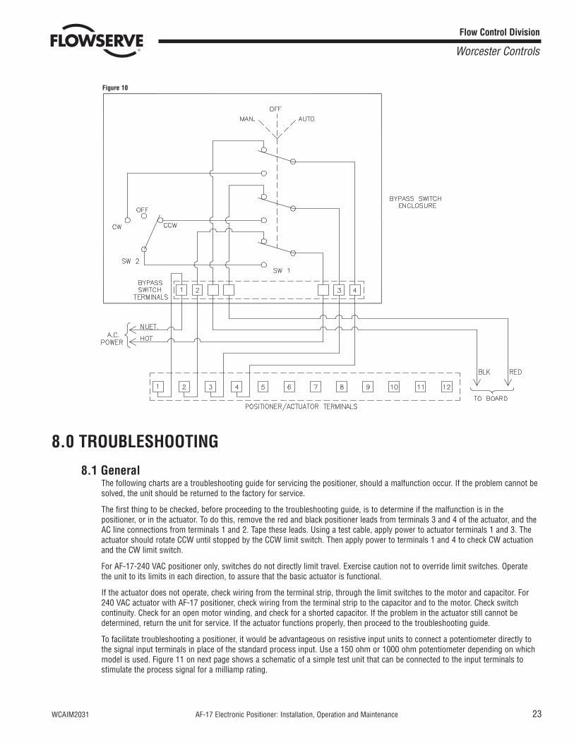
7.2 Bypass Switch for Manual Control (For 120 VAC Only)This application is offered as a non-standard option through Flowserve’s Custom Products Department or may be altered by enduser. Figure 10 on the next page shows a schematic diagram of two switches for controlling the following functions:
One triple-pole, double-throw (TPDT) switch with center-off, switching from automatic to manual operation.
One single-pole, double-throw (SPDT) switch with center-off position for manually controlling clockwise (CW), counter-clockwise(CCW) directions of actuator.
Figure 9
22 AF-17 Electronic Positioner: Installation, Operation and Maintenance WCAIM2031
Flow Control Division
Worcester Controls
8.0 TROUBLESHOOTING
8.1 GeneralThe following charts are a troubleshooting guide for servicing the positioner, should a malfunction occur. If the problem cannot besolved, the unit should be returned to the factory for service.
The first thing to be checked, before proceeding to the troubleshooting guide, is to determine if the malfunction is in thepositioner, or in the actuator. To do this, remove the red and black positioner leads from terminals 3 and 4 of the actuator, and theAC line connections from terminals 1 and 2. Tape these leads. Using a test cable, apply power to actuator terminals 1 and 3. Theactuator should rotate CCW until stopped by the CCW limit switch. Then apply power to terminals 1 and 4 to check CW actuationand the CW limit switch.
For AF-17-240 VAC positioner only, switches do not directly limit travel. Exercise caution not to override limit switches. Operatethe unit to its limits in each direction, to assure that the basic actuator is functional.
If the actuator does not operate, check wiring from the terminal strip, through the limit switches to the motor and capacitor. For240 VAC actuator with AF-17 positioner, check wiring from the terminal strip to the capacitor and to the motor. Check switchcontinuity. Check for an open motor winding, and check for a shorted capacitor. If the problem in the actuator still cannot bedetermined, return the unit for service. If the actuator functions properly, then proceed to the troubleshooting guide.
To facilitate troubleshooting a positioner, it would be advantageous on resistive input units to connect a potentiometer directly tothe signal input terminals in place of the standard process input. Use a 150 ohm or 1000 ohm potentiometer depending on whichmodel is used. Figure 11 on next page shows a schematic of a simple test unit that can be connected to the input terminals tostimulate the process signal for a milliamp rating.
Figure 10
WCAIM2031 AF-17 Electronic Positioner: Installation, Operation and Maintenance 23
Flow Control Division
Worcester Controls
24 AF-17 Electronic Positioner: Installation, Operation and Maintenance WCAIM2031
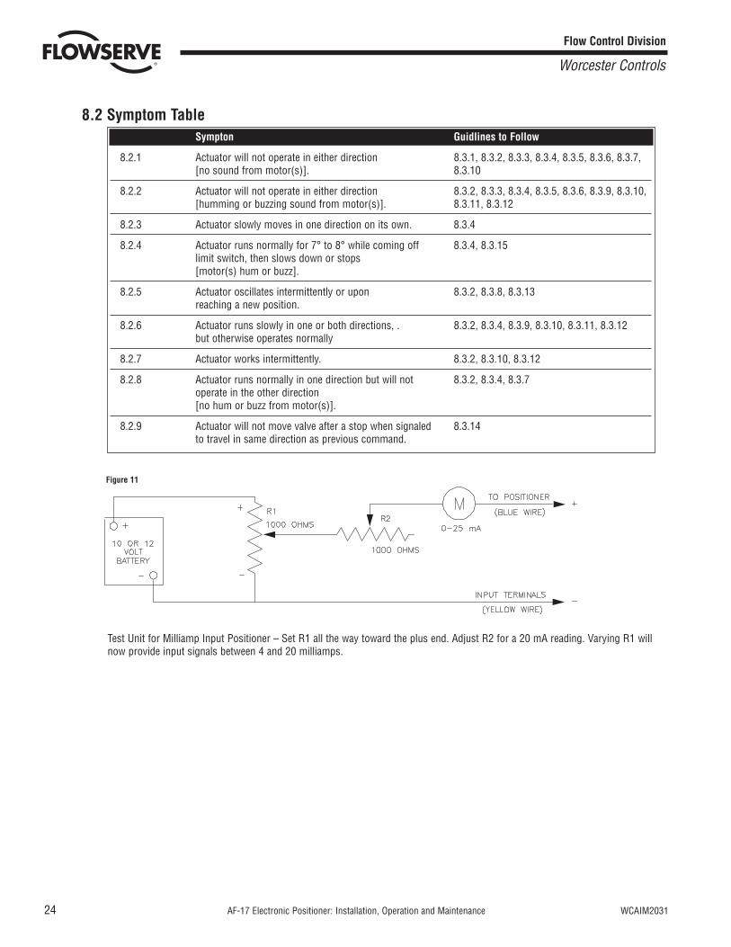
8.2 Symptom Table
Test Unit for Milliamp Input Positioner – Set R1 all the way toward the plus end. Adjust R2 for a 20 mA reading. Varying R1 willnow provide input signals between 4 and 20 milliamps.
Sympton Guidlines to Follow
8.2.1 Actuator will not operate in either direction 8.3.1, 8.3.2, 8.3.3, 8.3.4, 8.3.5, 8.3.6, 8.3.7, [no sound from motor(s)]. 8.3.10
8.2.2 Actuator will not operate in either direction 8.3.2, 8.3.3, 8.3.4, 8.3.5, 8.3.6, 8.3.9, 8.3.10, [humming or buzzing sound from motor(s)]. 8.3.11, 8.3.12
8.2.3 Actuator slowly moves in one direction on its own. 8.3.4
8.2.4 Actuator runs normally for 7° to 8° while coming off 8.3.4, 8.3.15limit switch, then slows down or stops [motor(s) hum or buzz].
8.2.5 Actuator oscillates intermittently or upon 8.3.2, 8.3.8, 8.3.13reaching a new position.
8.2.6 Actuator runs slowly in one or both directions, . 8.3.2, 8.3.4, 8.3.9, 8.3.10, 8.3.11, 8.3.12but otherwise operates normally
8.2.7 Actuator works intermittently. 8.3.2, 8.3.10, 8.3.12
8.2.8 Actuator runs normally in one direction but will not 8.3.2, 8.3.4, 8.3.7operate in the other direction [no hum or buzz from motor(s)].
8.2.9 Actuator will not move valve after a stop when signaled 8.3.14to travel in same direction as previous command.
Flow Control Division
Worcester Controls
Figure 11
WCAIM2031 AF-17 Electronic Positioner: Installation, Operation and Maintenance 25
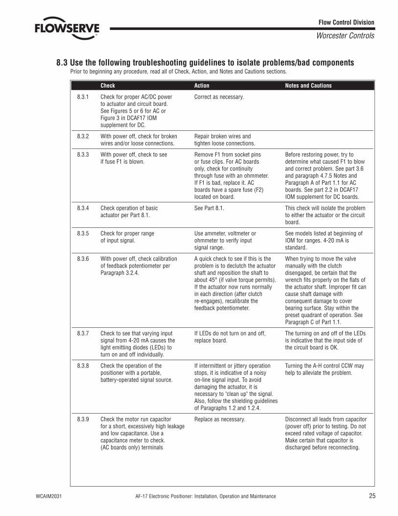
8.3 Use the following troubleshooting guidelines to isolate problems/bad componentsPrior to beginning any procedure, read all of Check, Action, and Notes and Cautions sections.
Flow Control Division
Worcester Controls
Check Action Notes and Cautions
8.3.1 Check for proper AC/DC power Correct as necessary.to actuator and circuit board. See Figures 5 or 6 for AC or Figure 3 in DCAF17 IOM supplement for DC.
8.3.2 With power off, check for broken Repair broken wires and wires and/or loose connections. tighten loose connections.
8.3.3 With power off, check to see Remove F1 from socket pins Before restoring power, try to if fuse F1 is blown. or fuse clips. For AC boards determine what caused F1 to blow
only, check for continuity and correct problem. See part 3.6through fuse with an ohmmeter. and paragraph 4.7.5 Notes and If F1 is bad, replace it. AC Paragraph A of Part 1.1 for AC boards have a spare fuse (F2) boards. See part 2.2 in DCAF17located on board. IOM supplement for DC boards.
8.3.4 Check operation of basic See Part 8.1. This check will isolate the problem actuator per Part 8.1. to either the actuator or the circuit
board.
8.3.5 Check for proper range Use ammeter, voltmeter or See models listed at beginning of of input signal. ohmmeter to verify input IOM for ranges. 4-20 mA is
signal range. standard.
8.3.6 With power off, check calibration A quick check to see if this is the When trying to move the valve of feedback potentiometer per problem is to declutch the actuator manually with the clutch Paragraph 3.2.4. shaft and reposition the shaft to disengaged, be certain that the
about 45° (if valve torque permits). wrench fits properly on the flats of If the actuator now runs normally the actuator shaft. Improper fit can in each direction (after clutch cause shaft damage with re-engages), recalibrate the consequent damage to cover feedback potentiometer. bearing surface. Stay within the
preset quadrant of operation. See Paragraph C of Part 1.1.
8.3.7 Check to see that varying input If LEDs do not turn on and off, The turning on and off of the LEDs signal from 4-20 mA causes the replace board. is indicative that the input side of light emitting diodes (LEDs) to the circuit board is OK.turn on and off individually.
8.3.8 Check the operation of the If intermittent or jittery operation Turning the A-H control CCW may positioner with a portable, stops, it is indicative of a noisy help to alleviate the problem.battery-operated signal source. on-line signal input. To avoid
damaging the actuator, it is necessary to "clean up" the signal. Also, follow the shielding guidelines of Paragraphs 1.2 and 1.2.4.
8.3.9 Check the motor run capacitor Replace as necessary. Disconnect all leads from capacitor for a short, excessively high leakage (power off) prior to testing. Do not and low capacitance. Use a exceed rated voltage of capacitor. capacitance meter to check. Make certain that capacitor is (AC boards only) terminals discharged before reconnecting.
26 AF-17 Electronic Positioner: Installation, Operation and Maintenance WCAIM2031
Flow Control Division
Worcester Controls
Check Action Notes and Cautions
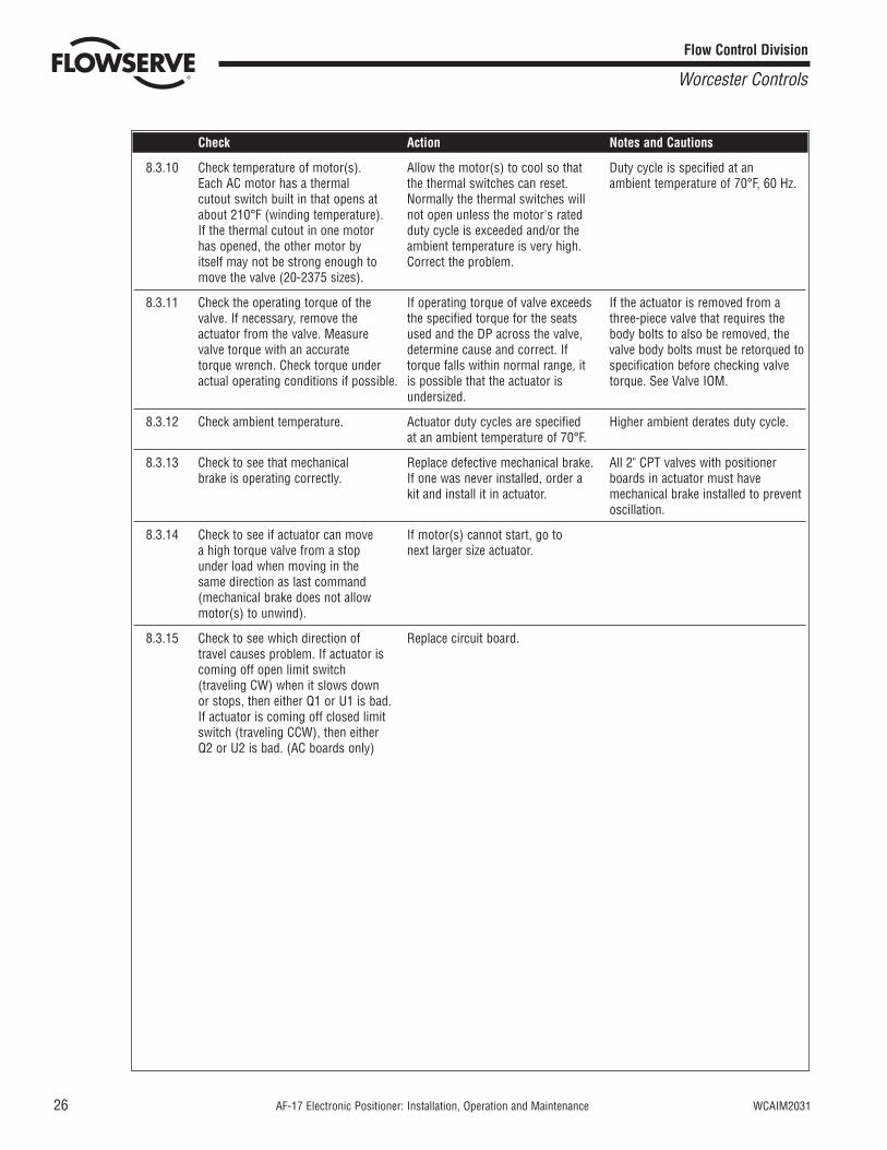
8.3.10 Check temperature of motor(s). Allow the motor(s) to cool so that Duty cycle is specified at an Each AC motor has a thermal the thermal switches can reset. ambient temperature of 70°F, 60 Hz.cutout switch built in that opens at Normally the thermal switches will about 210°F (winding temperature). not open unless the motor's rated If the thermal cutout in one motor duty cycle is exceeded and/or the has opened, the other motor by ambient temperature is very high. itself may not be strong enough to Correct the problem.move the valve (20-2375 sizes).
8.3.11 Check the operating torque of the If operating torque of valve exceeds If the actuator is removed from a valve. If necessary, remove the the specified torque for the seats three-piece valve that requires the actuator from the valve. Measure used and the DP across the valve, body bolts to also be removed, the valve torque with an accurate determine cause and correct. If valve body bolts must be retorqued to torque wrench. Check torque under torque falls within normal range, it specification before checking valve actual operating conditions if possible. is possible that the actuator is torque. See Valve IOM.
undersized.
8.3.12 Check ambient temperature. Actuator duty cycles are specified Higher ambient derates duty cycle.at an ambient temperature of 70°F.
8.3.13 Check to see that mechanical Replace defective mechanical brake. All 2" CPT valves with positioner brake is operating correctly. If one was never installed, order a boards in actuator must have
kit and install it in actuator. mechanical brake installed to prevent oscillation.
8.3.14 Check to see if actuator can move If motor(s) cannot start, go to a high torque valve from a stop next larger size actuator.under load when moving in the same direction as last command (mechanical brake does not allow motor(s) to unwind).
8.3.15 Check to see which direction of Replace circuit board.travel causes problem. If actuator is coming off open limit switch (traveling CW) when it slows down or stops, then either Q1 or U1 is bad. If actuator is coming off closed limit switch (traveling CCW), then either Q2 or U2 is bad. (AC boards only)

WCAIM2031 AF-17 Electronic Positioner: Installation, Operation and Maintenance 27
9.0 SUGGESTED SPARE PARTSIt is suggested that where 10 or more units are in service, one or more complete circuit boards be stocked as spares for ease ofmaintenance and minimum downtime. All circuit boards are wired directly to screw type terminal strips (no solder connections) and canbe easily changed on location.
Fuse F2 is a spare fuse attached to AC circuit boards but not wired in the circuit. See Figure 1. If fuse F2 is used to replace fuse F1, it isrecommended that another be purchased and attached to circuit board as a spare.
Flow Control Division
Worcester Controls
Flow Control Division
Worcester Controls
Flowserve Corporation has established industry leadership in the design and manufacture of its products. When properly selected, this Flowserve product is designed to perform its intended functionsafely during its useful life. However, the purchaser or user of Flowserve products should be aware that Flowserve products might be used in numerous applications under a wide variety of industrialservice conditions. Although Flowserve can (and often does) provide general guidelines, it cannot provide specific data and warnings for all possible applications. The purchaser/user must thereforeassume the ultimate responsibility for the proper sizing and selection, installation, operation, and maintenance of Flowserve products. The purchaser/user should read and understand the InstallationOperation Maintenance (IOM) instructions included with the product, and train its employees and contractors in the safe use of Flowserve products in connection with the specific application.
While the information and specifications contained in this literature are believed to be accurate, they are supplied for informative purposes only and should not be considered certified or as a guarantee ofsatisfactory results by reliance thereon. Nothing contained herein is to be construed as a warranty or guarantee, express or implied, regarding any matter with respect to this product. Because Flowserveis continually improving and upgrading its product design, the specifications, dimensions and information contained herein are subject to change without notice. Should any question arise concerningthese provisions, the purchaser/user should contact Flowserve Corporation at any one of its worldwide operations or offices.
For more information about Flowserve Corporation, contact www.flowserve.com or call USA 1-800-225-6989.
FLOWSERVE CORPORATIONFLOW CONTROL DIVISION1978 Foreman DriveCookeville, Tennessee 38501 USAPhone: 931 432 4021Facsimile: 931 432 3105www.flowserve.com
© 2003 Flowserve Corporation, Irving, Texas, USA. Flowserve and Worcester Controls are registered trademarks of Flowserve Corporation. WCAIM2031 10/03 Printed in USA