Embed Size (px)
Citation preview
www.aeroplusrc.com [email protected]
AeroPlus RC Copyright 2013 © All Rights Reserved
Sbach 342 50CC Item No:A‐G050001 Specifications Wing Span 88"(2235mm) Length 81"(2060mm) Wing Area 1463sq in(94.4sq dm) Flying Weight 16‐17lbs(7200‐7700g) Gasoline 50‐60cc gas Radio 4CH/6S Description Covering Material Genuine Oracover Carbon Fibre : wing tube and sleeves, landing gear, tail gear;
Fibreglass servo arms, horn and reinforced U/C mounting Fiberglass servo arms and horn; built‐in tuned pipe or canister tunnel; Pre Plumbed Tank Removeable Wings, Stabs and Rudders; Adjustable pushrods; Ringed Cowl; Pre drilled hinges
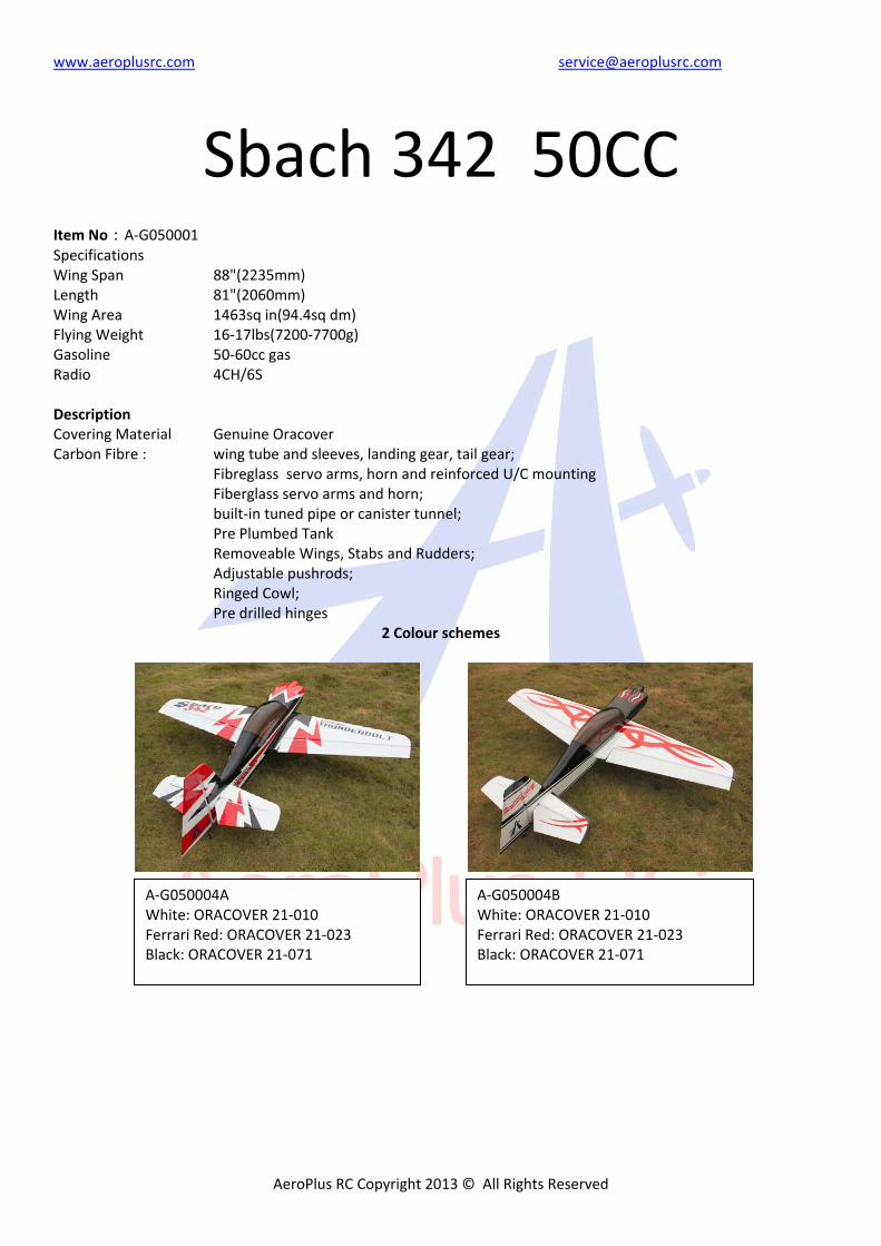
2 Colour schemes
A‐G050004B White: ORACOVER 21‐010 Ferrari Red: ORACOVER 21‐023 Black: ORACOVER 21‐071
A‐G050004A White: ORACOVER 21‐010 Ferrari Red: ORACOVER 21‐023 Black: ORACOVER 21‐071
www.aeroplusrc.com [email protected]
AeroPlus RC Copyright 2013 © All Rights Reserved
Unpacking Carefully unpack the model making sure that if you use a sharp knife to open bags, not to cut any covering on the model. Inspect each item to make sure no transit damage has happened. If you are not happy with any part or are unsure please contact the Dealer that you purchased from. Covering Due to the model spending time in different climates zones from the factory on its way to you, some of the covering may have wrinkles. We highly recommend that you take time to re‐seal all covering edges with an iron and to use a heat gun to remove any wrinkles and re‐tighten the covering. It is best to do this now while the plane is not assembled, remember to not let any heat get near any parts like the canopy or cowl as this may cause damage. Assembly Tips We also recommend that you go over all the accessible joints with cyano glue. Wick glue into areas of high stress around the U/C plate and motor box. Use Nutlock on all metal to metal joints. Even if you are using electric with low vibration levels it will make sure that things do not drop off your airplane!!
www.aeroplusrc.com [email protected]
AeroPlus RC Copyright 2013 © All Rights Reserved
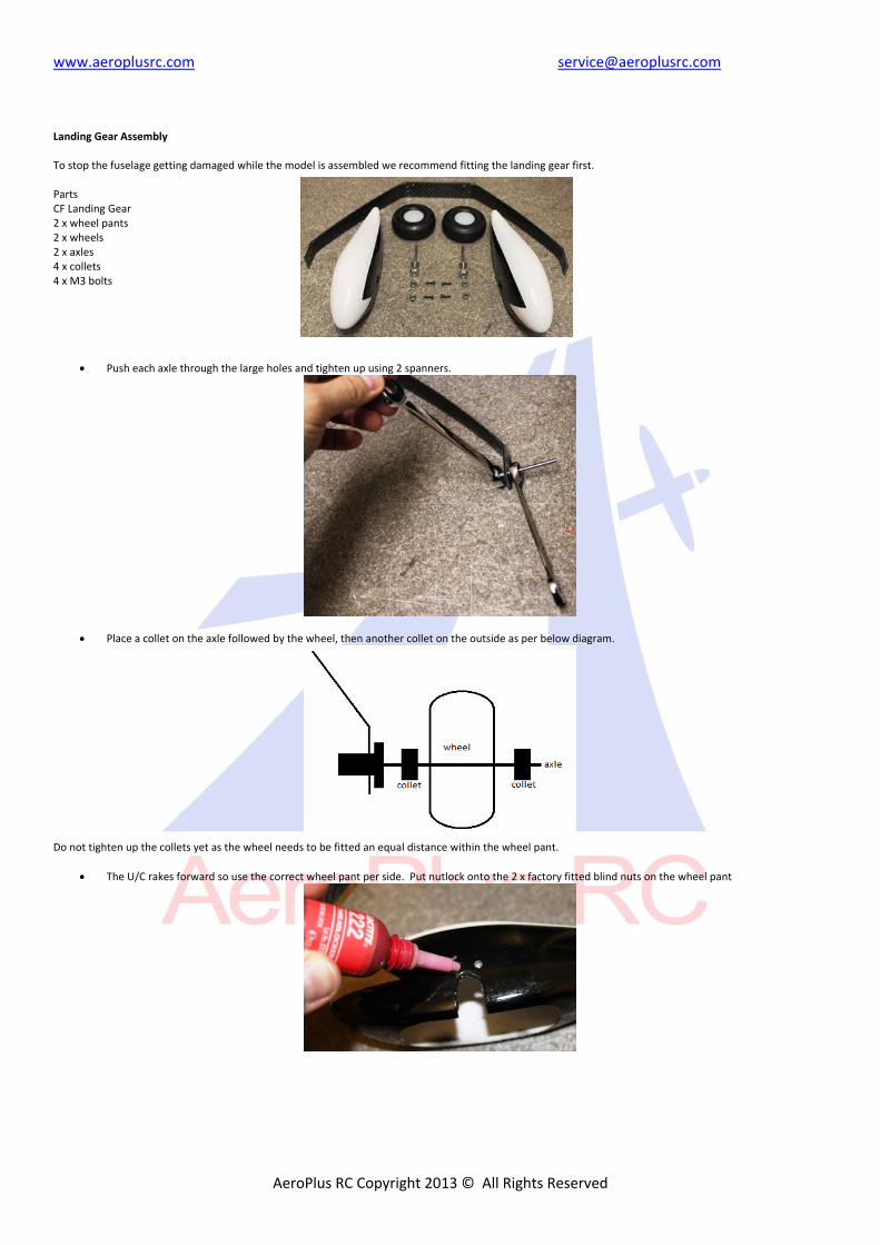
Landing Gear Assembly To stop the fuselage getting damaged while the model is assembled we recommend fitting the landing gear first. Parts CF Landing Gear 2 x wheel pants 2 x wheels 2 x axles 4 x collets 4 x M3 bolts
Push each axle through the large holes and tighten up using 2 spanners.
Place a collet on the axle followed by the wheel, then another collet on the outside as per below diagram.
Do not tighten up the collets yet as the wheel needs to be fitted an equal distance within the wheel pant.
The U/C rakes forward so use the correct wheel pant per side. Put nutlock onto the 2 x factory fitted blind nuts on the wheel pant
www.aeroplusrc.com [email protected]
AeroPlus RC Copyright 2013 © All Rights Reserved
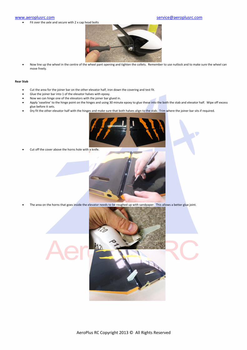
Fit over the axle and secure with 2 x cap head bolts
Now line up the wheel in the centre of the wheel pant opening and tighten the collets. Remember to use nutlock and to make sure the wheel can
move freely.
Rear Stab
Cut the area for the joiner bar on the other elevator half, iron down the covering and test fit.
Glue the joiner bar into 1 of the elevator halves with epoxy.
Now we can hinge one of the elevators with the joiner bar glued in.
Apply ‘vaseline’ to the hinge point on the hinges and using 30 minute epoxy to glue these into the both the stab and elevator half. Wipe off excess glue before it sets.
Dry fit the other elevator half with the hinges and make sure that both halves align to the stab. Trim where the joiner bar sits if required.
Cut off the cover above the horns hole with a knife.
The area on the horns that goes inside the elevator needs to be roughed up with sandpaper. This allows a better glue joint.
www.aeroplusrc.com [email protected]
AeroPlus RC Copyright 2013 © All Rights Reserved
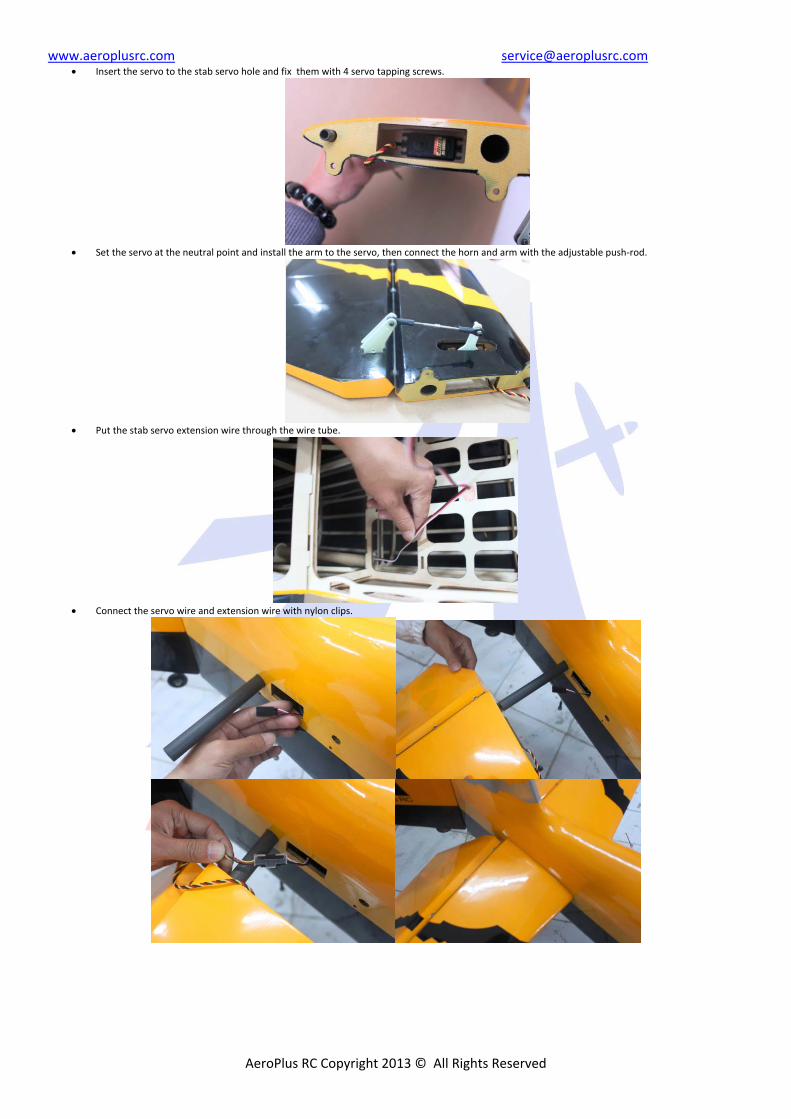
Insert the servo to the stab servo hole and fix them with 4 servo tapping screws.
Set the servo at the neutral point and install the arm to the servo, then connect the horn and arm with the adjustable push‐rod.
Put the stab servo extension wire through the wire tube.
Connect the servo wire and extension wire with nylon clips.
www.aeroplusrc.com [email protected]
AeroPlus RC Copyright 2013 © All Rights Reserved
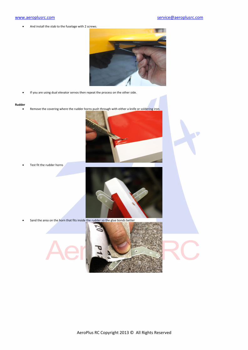
And install the stab to the fuselage with 2 screws.
If you are using dual elevator servos then repeat the process on the other side. Rudder
Remove the covering where the rudder horns push through with either a knife or soldering iron.
Test fit the rudder horns
Sand the area on the horn that fits inside the rudder so the glue bonds better
www.aeroplusrc.com [email protected]
AeroPlus RC Copyright 2013 © All Rights Reserved
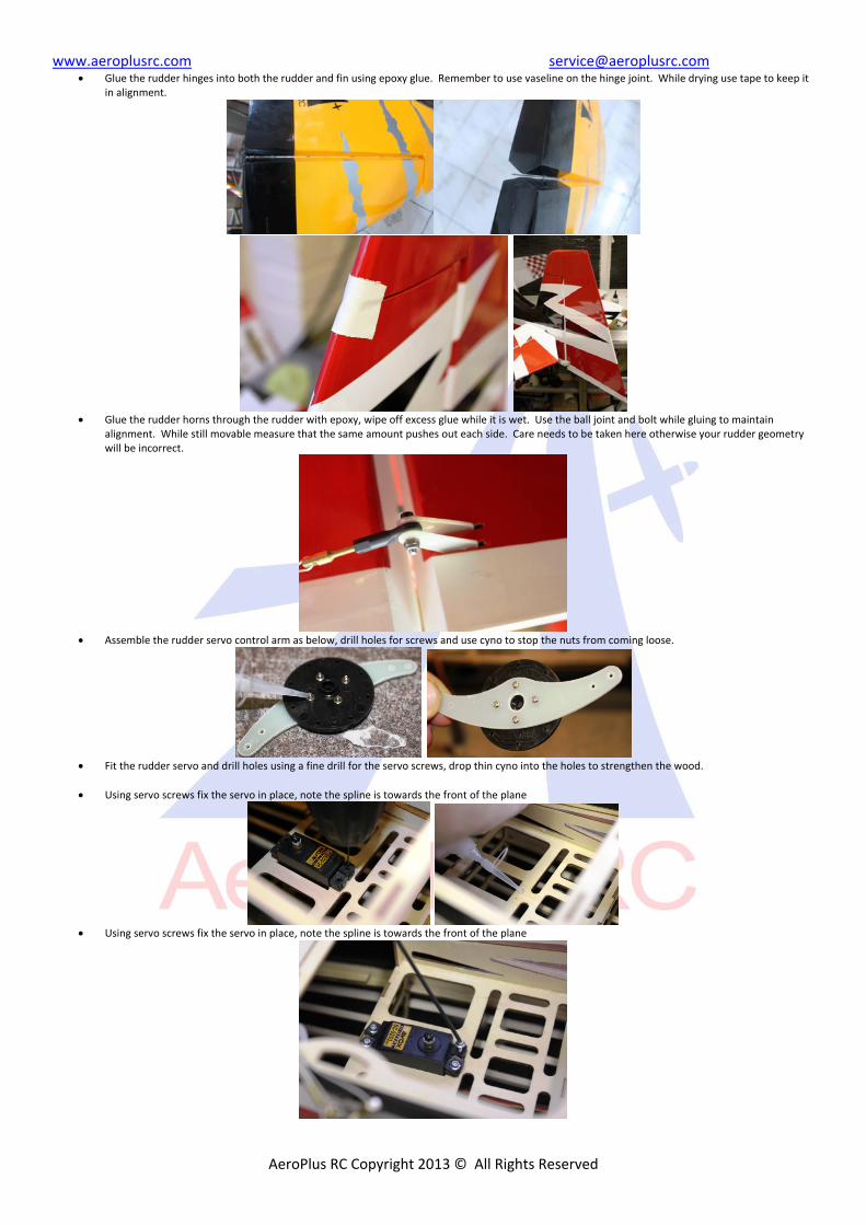
Glue the rudder hinges into both the rudder and fin using epoxy glue. Remember to use vaseline on the hinge joint. While drying use tape to keep it in alignment.
Glue the rudder horns through the rudder with epoxy, wipe off excess glue while it is wet. Use the ball joint and bolt while gluing to maintain
alignment. While still movable measure that the same amount pushes out each side. Care needs to be taken here otherwise your rudder geometry will be incorrect.
Assemble the rudder servo control arm as below, drill holes for screws and use cyno to stop the nuts from coming loose.
Fit the rudder servo and drill holes using a fine drill for the servo screws, drop thin cyno into the holes to strengthen the wood.
Using servo screws fix the servo in place, note the spline is towards the front of the plane
Using servo screws fix the servo in place, note the spline is towards the front of the plane
www.aeroplusrc.com [email protected]
AeroPlus RC Copyright 2013 © All Rights Reserved
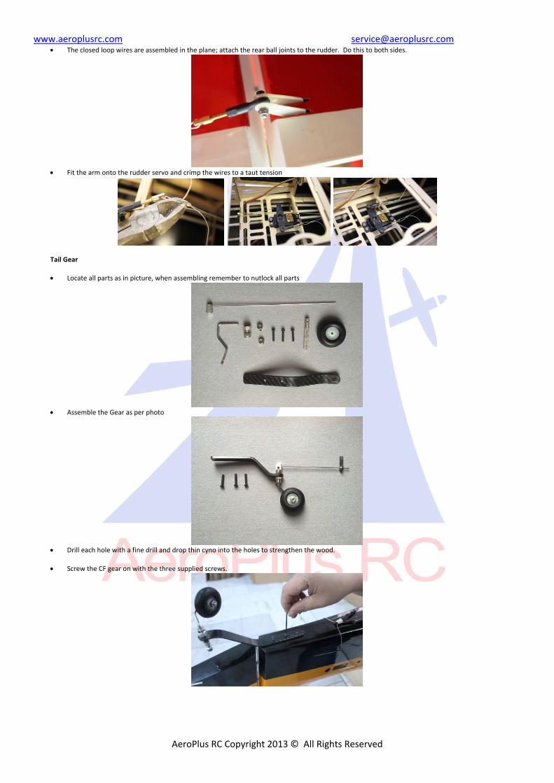
The closed loop wires are assembled in the plane; attach the rear ball joints to the rudder. Do this to both sides.
Fit the arm onto the rudder servo and crimp the wires to a taut tension
Tail Gear
Locate all parts as in picture, when assembling remember to nutlock all parts
Assemble the Gear as per photo
Drill each hole with a fine drill and drop thin cyno into the holes to strengthen the wood.
Screw the CF gear on with the three supplied screws.
www.aeroplusrc.com [email protected]
AeroPlus RC Copyright 2013 © All Rights Reserved
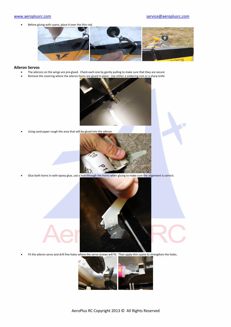
Before gluing with cyano, place it over the thin rod.
Aileron Servos The ailerons on the wings are pre‐glued. Check each one by gently pulling to make sure that they are secure
Remove the covering where the aileron horns are glued in place. Use either a soldering iron or a sharp knife
Using sand paper rough the area that will be glued into the aileron.
Glue both horns in with epoxy glue, use a bolt through the horns when gluing to make sure the alignment is correct.
Fit the aileron servo and drill fine holes where the servo screws will fit. Then apply thin cyano to strengthen the holes.
www.aeroplusrc.com [email protected]
AeroPlus RC Copyright 2013 © All Rights Reserved
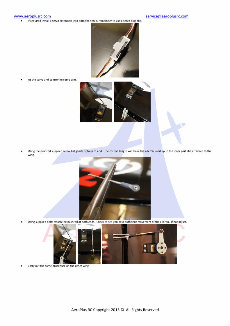
If required install a servo extension lead onto the servo, remember to use a servo plug clip.
Fit the servo and centre the servo arm.
Using the pushrod supplied screw ball joints onto each end. The correct length will leave the aileron lined up to the inner part still attached to the wing.
Using supplied bolts attach the pushrod at both ends. Check to see you have sufficient movement of the aileron. If not adjust.
Carry out the same procedure on the other wing.
www.aeroplusrc.com [email protected]
AeroPlus RC Copyright 2013 © All Rights Reserved
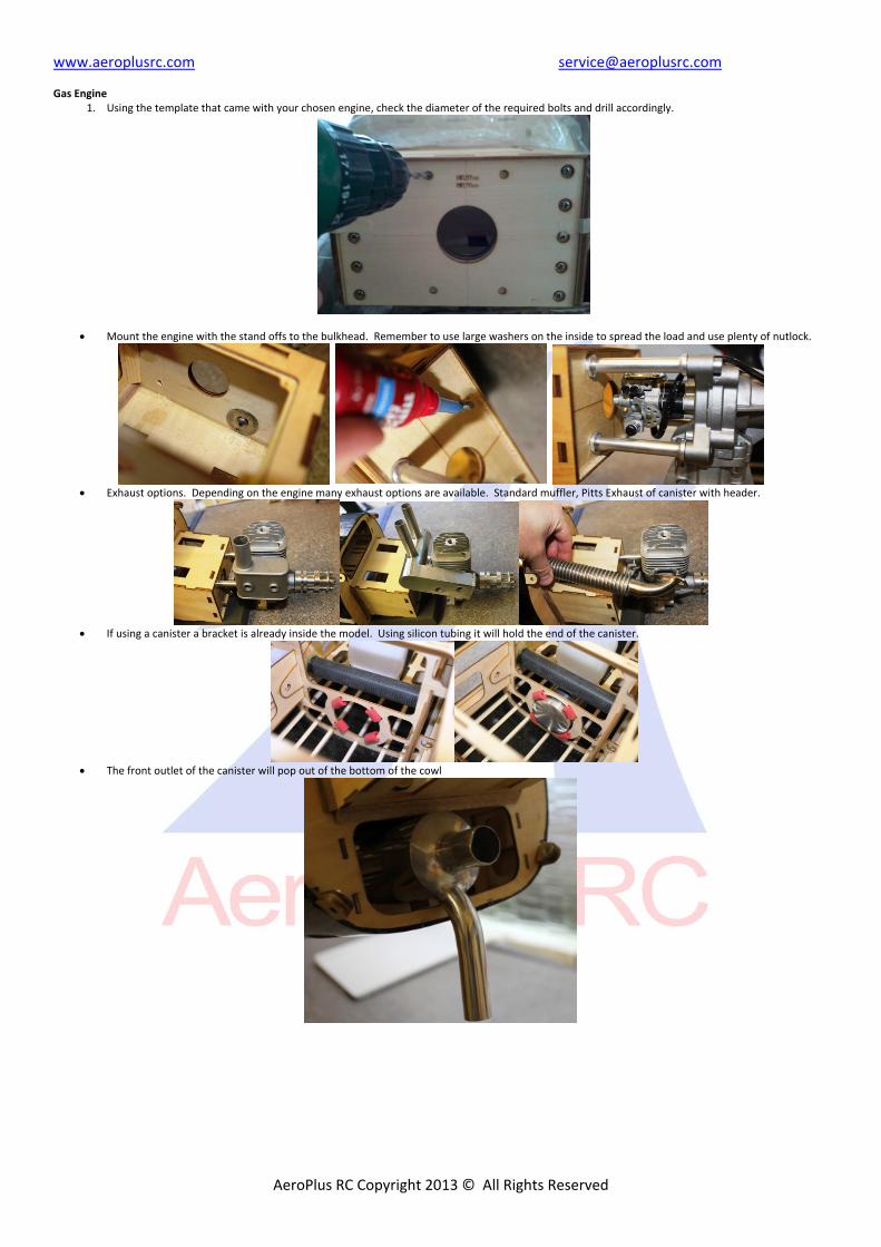
Gas Engine
1. Using the template that came with your chosen engine, check the diameter of the required bolts and drill accordingly.
Mount the engine with the stand offs to the bulkhead. Remember to use large washers on the inside to spread the load and use plenty of nutlock.
Exhaust options. Depending on the engine many exhaust options are available. Standard muffler, Pitts Exhaust of canister with header.
If using a canister a bracket is already inside the model. Using silicon tubing it will hold the end of the canister.
The front outlet of the canister will pop out of the bottom of the cowl
www.aeroplusrc.com [email protected]
AeroPlus RC Copyright 2013 © All Rights Reserved
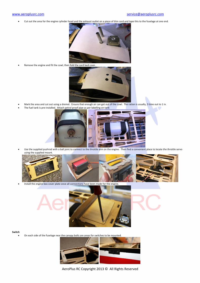
Cut out the area for the engine cylinder head and the exhaust outlet on a piece of thin card and tape this to the fuselage at one end.
Remove the engine and fit the cowl, then fold the card back over.
Mark the area and cut out using a dremel. Ensure that enough air can get out of the cowl. The ration is usually, 3 time out to 1 in.
The fuel tank is pre‐installed. Attach petrol proof pipe as per labelling on tank
Use the supplied pushrod with a ball joint to connect to the throttle arm on the engine. Then find a convenient place to locate the throttle servo
using the supplied mount.
Install the engine box cover plate once all connections have been made for the engine.
Switch
On each side of the fuselage near the canopy bolts are areas for switches to be mounted.
www.aeroplusrc.com [email protected]
AeroPlus RC Copyright 2013 © All Rights Reserved
RX
A convienient place to mount the RX is just in front of the rudder servo. Ensure that it is mounted on velco and strapped down.
Canopy
The canopy is held in place with the 2 thumb screws, ensure these are tight before flying
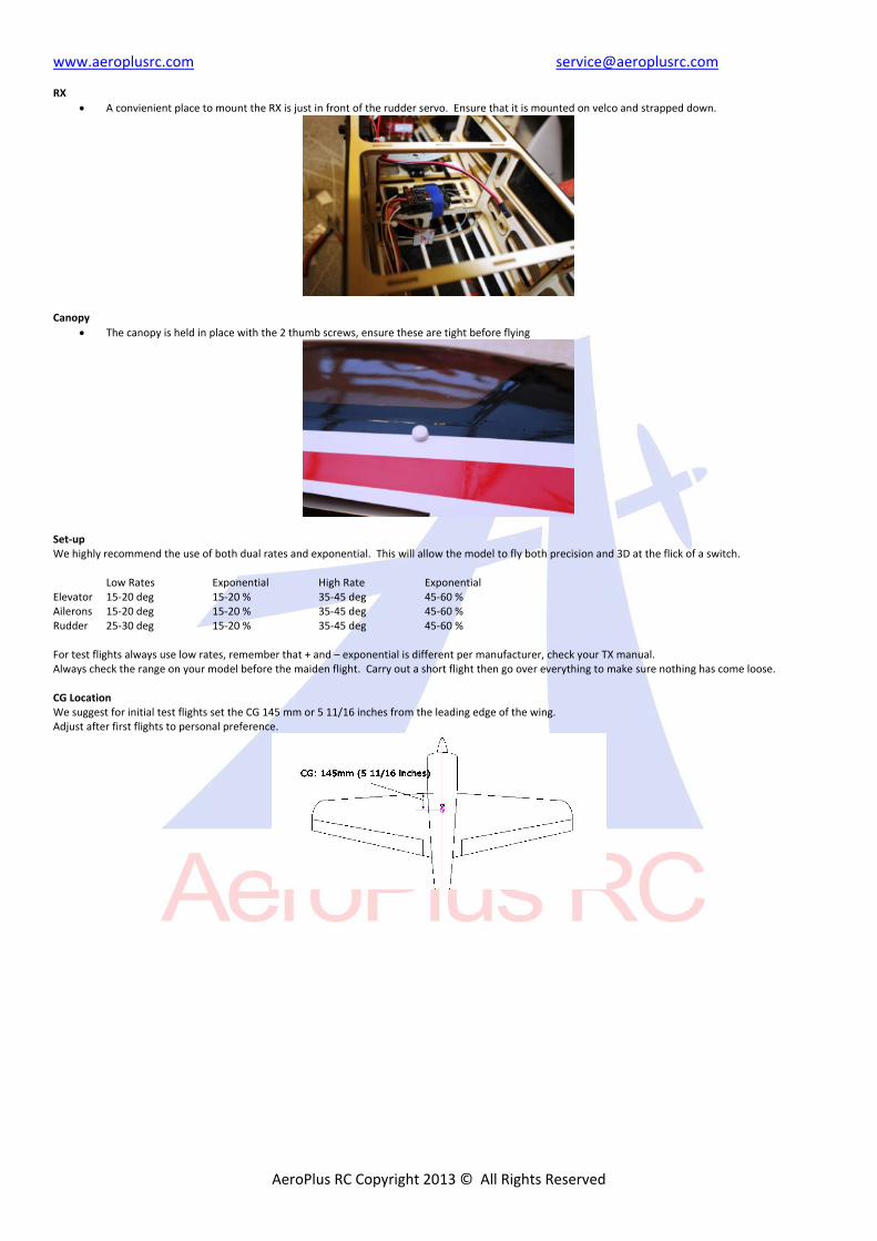
Set‐up We highly recommend the use of both dual rates and exponential. This will allow the model to fly both precision and 3D at the flick of a switch.
Low Rates Exponential High Rate Exponential Elevator 15‐20 deg 15‐20 % 35‐45 deg 45‐60 % Ailerons 15‐20 deg 15‐20 % 35‐45 deg 45‐60 % Rudder 25‐30 deg 15‐20 % 35‐45 deg 45‐60 % For test flights always use low rates, remember that + and – exponential is different per manufacturer, check your TX manual. Always check the range on your model before the maiden flight. Carry out a short flight then go over everything to make sure nothing has come loose. CG Location We suggest for initial test flights set the CG 145 mm or 5 11/16 inches from the leading edge of the wing. Adjust after first flights to personal preference.