Embed Size (px)
Citation preview

ADX-140
NETWORKED AUDIO INTERFACE UNIT
(Cobranet Version)
Installation and Operation Manual
Firmware Version 5.5
Lance Design / 27 Fairview Avenue / Ridgefield, Connecticut 06877Tel: 203-894-8206 / Fax: 203-894-8207
www.lancedesign.com
2
WARRANTY STATEMENT
This equipment is warranted to be free of defects in materials and workmanship for a period of two years from date of delivery. Any necessary repairs resulting from defects in materials or in manufacture will be made free of charge provided that the equipment has not been subjected to mechanical or electrical abuse, or modification, as determined by Lance Design, and also that the equipment is returned to Lance Design with prior authorization.
No liability whatsoever is assumed for consequential damages resulting from the use or failure of this equipment. This warranty is in lieu of all other warranties, expressed or implied, including any implied warranty of fitness for purpose.
COPYRIGHT
All software and hardware designs are copyrighted to Lance Design, 2010-2017.
3
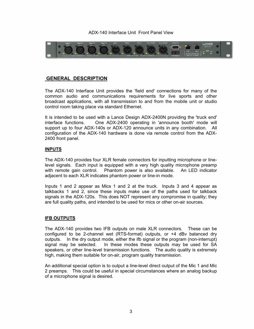
ADX-140 Interface Unit Front Panel View
GENERAL DESCRIPTION
The ADX-140 Interface Unit provides the 'field end' connections for many of the common audio and communications requirements for live sports and other broadcast applications, with all transmission to and from the mobile unit or studio control room taking place via standard Ethernet.
It is intended to be used with a Lance Design ADX-2400N providing the 'truck end' interface functions. One ADX-2400 operating in 'announce booth' mode will support up to four ADX-140s or ADX-120 announce units in any combination. All configuration of the ADX-140 hardware is done via remote control from the ADX-2400 front panel.
INPUTS
The ADX-140 provides four XLR female connectors for inputting microphone or line-level signals. Each input is equipped with a very high quality microphone preamp with remote gain control. Phantom power is also available. An LED indicator adjacent to each XLR indicates phantom power or line-in mode.
Inputs 1 and 2 appear as Mics 1 and 2 at the truck. Inputs 3 and 4 appear as talkbacks 1 and 2, since these inputs make use of the paths used for talkback signals in the ADX-120s. This does NOT represent any compromise in quality; they are full quality paths, and intended to be used for mics or other on-air sources.
IFB OUTPUTS
The ADX-140 provides two IFB outputs on male XLR connectors. These can be configured to be 2-channel wet (RTS-format) outputs, or +4 dBv balanced dry outputs. In the dry output mode, either the ifb signal or the program (non-interrupt) signal may be selected. In these modes these outputs may be used for SA speakers, or other line-level transmission functions. The audio quality is extremely high, making them suitable for on-air, program quality transmission.
An additional special option is to output a line-level direct output of the Mic 1 and Mic 2 preamps. This could be useful in special circumstances where an analog backup of a microphone signal is desired.
4
PL (INTERCOM) CONNECTIONS
The ADX-140 provides a high-quality interface for two channels of RTS-format TW (wet) intercom. The ADX-140 provides power supplies and four-wire to two-wire conversion internally, so no additional hardware is required. The PL connections are available on three male XLR connectors. The first combines PL channel 1 and PL channel 2 in the traditional RTS two-channel configuration. The other two channels provide one channel of wet PL and one channel of program (non-interrupt) audio. This prevents having to use a PL channel just to provide program audio on the second channel of the beltpacks.
Each IFB and PL power supply is individually protected for shorts and overloads, with a front panel indication of these conditions. The PL supplies can supply current for up to three beltpacks on PL 1 or PL 2. The IFB supplies can supply current for two beltpacks each. The total number of beltpacks (PL and IFB combined) should not exceed 6 per ADX-140.
Special care has been taken in the design of the PL sections. The hybrids (two-wire to four-wire conversion) are carefully designed to provide good bandwidth and noise performance, as well as a high level of trans-hybrid loss. In addition there are noise gates implemented in the dsp to provide additional quieting. Because the long-distance portions of the intercom are transmitted via a digital path and in four-wire format, the PL performance far exceeds what is typically achieved with two-wire systems in terms of response, noise, distortion, headroom, etc.
TALKBACK OPERATION
The ADX-140 provides the option of using external talent talkback switches (handheld switches or foot switches). These may be connected via the remote connector, and enabled via menu item 15 (GPI enable). When talkback GPI 1 is activated, MIC 1 is muted, and the mic 1 audio is routed to the MIC 3 (TB1) path. GPI 2 provides the same function for MIC 2 via the MIC 4 (TB2) path.
See the REMOTE pinout on page 22 for connection information.
POWER
The ADX-140 may be powered in either of two ways: There is a wide-range AC input on the rear panel (95-250 Volts, 50/60 Hz), or the unit may be powered via the Cat5 Ethernet cable from an ADX-8000 switch/power supply.
Both methods may be used simultaneously if desired to provide redundancy.

5
System Overview
The ADX announce system consists of the following elements:
One or more ADX-2400 frames which serve as the 'head end' or truck end of the system, and provide all inputs and and outputs for the truck or control room. These units are available with analog, AES, or MADI I/O.
One or more ADX-120 Announce Boxes or ADX-140 Interface Frames which function as the remote units in the booth or other remote location.
ADX-8000 or other 48-volt power supplies as required to power the ADX-120 units. The ADX-140 and the ADX-2400 have internal AC-operated supplies, although the ADX-140 may also be powered over the CAT5 cable from an external 48-volt supply (such as the ADX-8000).
Network infrastructure as required, consisting of standard layer-2 Ethernet switches, fiber optic elements, media converters, fiber and copper interconnects, etc. This is referred to in this manual as 'the network'.
Each ADX-2400 unit can support up to four ADX-120 or ADX-140 units, in any combination.
The remote devices are identified by the ADX-2400s by a SYSTEM ID number, which is set by a two-digit rotary switch on the remote device (rear panel of the ADX-120, front panel of the ADX-140). Each remote device must be set to a unique system ID (01-99).
The desired remote devices are designated in the ADX-2400 menu to be 'UNIT A', 'UNIT B', 'UNIT C' and 'UNIT D' for that ADX-2400. This is what determines the audio routing; for example which microphone signal comes out of the 'Mic A1' output of the ADX-2400. The microphone signal that comes out of that output would be the headset mic ("Mic 1") from the ADX-120 which has its system ID switches set to match the number assigned as 'Unit A' in the ADX-2400 menus.
Note that network wiring has no bearing on the audio routing. An announce box can be plugged in anywhere on the network, into any cable, and the routing will remain constant. This could be very useful if you had to move an announce position to a second location. All faders, IFBs, PLs etc. would remain the same at the second location without any duplication or re-patching/routing at the truck.
As another example, if you needed to swap the color and play-by-play positions for some reason, you could just change the System ID switches on their announce boxes. All mikes, IFBs, talkbacks, etc. would be swapped automatically.
Note that the network which connects the system components is a true Ethernet network, and may be as extensive and as distributed as required. It is not simply a point to point system. Network nodes might be in a booth, mobile unit, locker room, sideline, and interview studio; all connected by a combination of fiber and Cat5 cable.
6
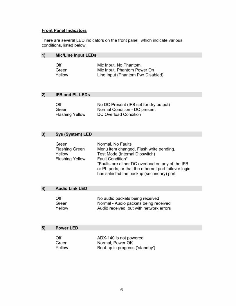
Front Panel Indicators
There are several LED indicators on the front panel, which indicate various conditions, listed below.
1) Mic/Line Input LEDs
Off Mic Input, No PhantomGreen Mic Input, Phantom Power OnYellow Line Input (Phantom Pwr Disabled)
2) IFB and PL LEDs
Off No DC Present (IFB set for dry output)Green Normal Condition - DC presentFlashing Yellow DC Overload Condition
3) Sys (System) LED
Green Normal, No FaultsFlashing Green Menu item changed, Flash write pending.Yellow Test Mode (Internal Dipswitch)Flashing Yellow Fault Condition*
*Faults are either DC overload on any of the IFBor PL ports, or that the ethernet port failover logichas selected the backup (secondary) port.
4) Audio Link LED
Off No audio packets being receivedGreen Normal - Audio packets being receivedYellow Audio received, but with network errors
5) Power LED
Off ADX-140 is not poweredGreen Normal, Power OKYellow Boot-up in progress ('standby')

7
The Truck End
ADX-2400N Front Panel
The ADX-140 Interface Units connect via Ethernet (copper or fiber) to a standard ADX-2400 Audio Distribution unit in the truck. These units are available in either analog or AES configurations, and have been well-proven through several years of widespread application in high-end mobile units and other applications.
When the option dip switch section #3 is turned on, the ADX-2400 enters the ‘announce booth mode’. In this mode, the ADX-2400 is configured for low-latency operation, and its DSPs are programmed to provide for such things as talkback selection and mixing, PL port assignments, non-interrupt (‘program’) selection, and IFB interrupt selection.
Each ADX-2400 can support up to four ADX-120s or ADX-140s, thereby taking advantage of all 24 outgoing paths and all 24 incoming paths. The ADX-120s and ADX-140s in use are distinguished from each other by the System ID numbers set on the switches on each unit, and are assigned to be 'Unit A', 'Unit B', 'Unit C' and 'Unit D' in the ADX-2400 menu.
Front panel metering and headphone monitoring is available for all paths.
ADX-2400N Rear Panel
All DB25 connectors are wired in the industry-standard Tascam/Pro Tools format, and breakout cables and pre-wired jackfields are available from a wide variety of suppliers. One is Audio Accessories, Inc. (www.patchbays.com)
The functional designations for the physical inputs and outputs are listed on the following pages.

8
The ADX-2400N Physical Rear Panel Outputs are:
Out 1 Mic A1 Out (ADX120 Hdst Mic; ADX140 Input 1)Out 2 Mic A2 Out (ADX120 Rear Panel; ADX140 Input 2)Out 3 Mic B1 OutOut 4 Mic B2 OutOut 5 Mic C1 OutOut 6 Mic C2 OutOut 7 Mic D1 OutOut 8 Mic D2 Out
Out 9 Talkback Output 1 (Each physical Talkback output may be fedOut 10 Talkback Output 2 by any of the Talkback paths from the ADX-Out 11 Talkback Output 3 120s, Inputs 3 and 4 of the ADX-140s, or Out 12 Talkback Output 4 various mixes)Out 13 Talkback Output 5Out 14 Talkback Output 6Out 15 Talkback Output 7Out 16 Talkback Output 8
Out 17 4-Wire PL Port 1 Out (Each PL channel at the ADX-120/140sOut 18 4-Wire PL Port 2 Out may be assigned to any of the 4-wireOut 19 4-Wire PL Port 3 Out ports. )Out 20 4-Wire PL Port 4 Out )Out 21 4-Wire PL Port 5 OutOut 22 4-Wire PL Port 6 OutOut 23 4-Wire PL Port 7 OutOut 24 4-Wire PL Port 8 Out
The ADX-2400N Physical Rear Panel Inputs are:
Input 1 IFB In 1 (Each IFB output at the ADX140s may be fedInput 2 IFB In 2 from any of the eight physical IFB inputs)Input 3 IFB In 3Input 4 IFB In 4Input 5 IFB In 5Input 6 IFB In 6Input 7 IFB In 7Input 8 IFB In 8
Input 9 PGM In 1 (Each PGM output at the ADX140s may be fedInput 10 PGM In 2 from any of the eight physical PGM inputs)Input 11 PGM In 3Input 12 PGM In 4Input 13 PGM In 5Input 14 PGM In 6Input 15 PGM In 7Input 16 PGM In 8
(continued)

9
Input 17 4-Wire PL Port 1 In (Input side of 4W PL Interface. See above)Input 18 4-Wire PL Port 2 InInput 19 4-Wire PL Port 3 InInput 20 4-Wire PL Port 4 InInput 21 4-Wire PL Port 5 InInput 22 4-Wire PL Port 6 InInput 23 4-Wire PL Port 7 InInput 24 4-Wire PL Port 8 In
Note that there are routers in the ADX2400 for the following:
Talkback paths from the announce boxes to physical Talkback outputs. Mixes may also be selected so that external talkback mixing is not required.
Physical IFB inputs at the truck to the various IFB outputs on the ADX-120/140 units. One physical input may feed multiple IFB outputs.
Physical PGM inputs at the truck to the various PGM outputs on the ADX-120/140 units. One physical input may feed multiple PGM outputs.
Four-wire PL Ports to the various PL channels on the ADX-120/140 units. Any PL channel on the ADX-120/140s may be assigned to any four-wire port. The appropriate mix-minus signals will automatically be generated, similar to the 'party-line' function in the Adam intercom systesm.
This routing is controlled by the 'SOURCE' selections on the ADX-2400 for the various outputs. See the configuration section for more information.
The AES and MADI versions of the ADX-2400 function in a very similar fashion. Please see the manuals for those units for more detailed information.

10
System Configuraton
Configuration of the system takes place both in the ADX-2400 and in the remote devices (ADX-120/140) themselves. This configuration is all done from the ADX-2400 front panel.
There are three catagories of configuration:
1. The ADX-2400 Menu Configuration
This is where the remote devices are assigned to be Units A, B, C, and D. There are no other config items except for saving and recalling the configurations to/ from user memory files, and some status displays.
2. The ADX-2400 Channel Setup
This is where 'truck-end' routing assignments are made for the talkback outputs, IFB and Program paths, and PL ports. These assignments are made using the OUTPUT SELECT and SOURCE buttons on the ADX-2400. The LEVEL button also is available to control output levels to both the rear-panel outputs and the outputs sent to the network and thus to the remote devices. The DELAY function is not available in announce booth mode.
3. The Remote Device menus
Each remote device (ADX-120/140) has an internal menu which may be accessed remotely via the ADX-2400.
These menus configure the hardware of the remote device itself, and are specific to the particular model, i.e. the ADX-120 has different options from the ADX-140 because of differences in their hardware capabilities.
These menus configure such things as preamp gain, phantom power, IFB output configurations, headset impedence (level), button color, etc.
These remote menu settings are saved in the remote devices themselves, and will remain associated with a particular device, even if it is moved or has its system ID reassigned. These settings are not stored in the ADX-2400 at the truck.
Status of many of the remote configuration items is displayed by LEDs on the remote devices (rear panel on the ADX-120s, front panel on the ADX-140s).

11
Setting System ID Switches
The System ID switches on each unit allow the system to distinguish one unit from another. Cobranet bundle numbers and Ethernet IP addresses are automatically determined based on the System ID Switches.
The System ID switches are two-digit rotary switches on the rear panel of the ADX-120 and on the front panel of the ADX-140. The ADX-2400 also has System ID switches, which are behind the removeable front panel, on the PCB sub-panel.
The range for the switches is from 01 through 99 (00 is not a valid ID). It doesn't matter what the numbers are set to be, so long as they all are unique.
The System ID settings for the ADX-120/140 units become the reference for the physical unit, and will be used in assigning those units to be A, B, C, and D designations in the ADX-2400 menus (see below).
Assigning the ADX120 / ADX140 to be Units A, B, C, or D
The announce units must first be assigned to be devices A, B, C, or D in the ADX2400 menu. To do this, press the MENU button once, and select config items 1, 2, 3, and 4 respectively using the knob. When the desired item is selected, press the MENU SET button and select the appropriate System ID number for the ADX120 or ADX140 you want to assign. Pressing either SET or MENU will take you back to the item select mode.
Note: If you're using a combination of ADX120 and ADX140 units it's best to assign the ADX120s as the 'lower' letters and the ADX140(s) as the 'higher' letters (e.g. 'D'). This is because channels 3 and 4 of the ADX140s are transmitted as 'talkback' outputs, but would typically not be included in a talkback mix. When you assign the talkback outputs of the ADX2400 the mix options are 'AB', 'ABC', and 'ABCD'. If you assign the ADX140 as D, for example, it's easy to exclude it from the mix.
Accessing Remote Menus from the ADX-2400
The configuration items for the ADX-120 and ADX-140 units are accessable from the front panel of the ADX-2400. To access these remote unit menus, double-clickthe MENU button on the ADX2400. The display will say: SELECT REMOTE DEVICE. The MENU button will be flashing to indicate that a remote device is being accessed.
(continued)

12
The menu display will look similar to this:
The number in the brackets is the System ID assigned in the ADX-2400 for Unit A (in this example). If the selected device is present on the network, it's model number and System ID number will be displayed (ADX140-01 in this example).
Scroll to the desired assigned device (either A, B, C or D).
Press MENU again. This will access the menu of the remote device, and the menu might look like this (depending on the type of device and the selected item):
The configuration and status items may be selected using the knob. Once the desired item is selected, press the MENU SET button to allow changing that item's settings. Settings are saved automatically after about 10 seconds of inactivity.
Press either MENU SET or MENU to go back to the item select mode.
When you're done, the easiest way out of any of the menu modes is to just press the OUTPUT SELECT button. This will cancel all menu modes, and you won't have to step backwards out of them.
ADX-140 Remote Menu Items
The ADX-140 menu items for firmware version 1.0 are listed below. These items may be accessed from the ADX-2400 front panel, or via the RS-232 remote port on the ADX-140 front panel (the 'Remote' connector).
Config Item 01 – Mic 1 Gain (25-70dB)Config Item 02 – Mic 2 Gain (25-70dB)Config Item 03 – Mic 3 Gain (25-70dB)Config Item 04 – Mic 4 Gain (25-70dB)These are the preamp gains for microphone inputs 1-4. They would typically run around 40 or 45 dB for normal sports use. A headroom indication is also provided in the lower right corner of the display (HR=XXdB). This headroom is calculated from the peak audio levels, and has about a one-second update rate. It is accurate, and will give a good indication of headroom before either preamp or A-to-D clipping. Note that if the channel is in the 'line in' mode, the preamp gain will not be displayed. Instead there will be a message indicating that the channel is in 'line in'. The gain will be fixed for unity-level transmission.
ADX140-01 Config Item 01Mic 1 Gain=45dB HR>30dB
Select Remote DeviceUnit A [01] ADX140-01

13
Config Item 05 – Channel 1 Input (Mic or Line)Config Item 06 – Channel 2 Input (Mic or Line)Config Item 07 – Channel 3 Input (Mic or Line)Config Item 08 – Channel 4 Input (Mic or Line)These select either mic or line input mode for the input channel. The nominal 0VU level is +4dBm. Output level at the truck is still adjustable on the ADX-2400. Line input mode is indicated by a yellow LED adjacent to the XLR input connector.
Config Item 09 – Mic 1 Phantom (On / Off)Config Item 10 – Mic 2 Phantom (On / Off)Config Item 11 – Mic 3 Phantom (On / Off)Config Item 12 – Mic 4 Phantom (On / Off)Turn on phantom power for Mics 1-4. Indicated by a green LED adjacent to the XLR. Phantom power is automatically turned off if line in mode is selected.
Config Item 13 – IFB 1 ModeControls the signal routing for the IFB 1 XLR output. The selections are as follows:
Wet 2 Ch - Configured as 2-ch RTS-format. IFB1 on Ch1, PGM1 on Ch2.Dry - IFB - Configured as dry balanced +4 output of IFB 1.Dry - PGM - Configured as dry balanced +4 output of PGM 1.Dry - Mic 1 - Configured as dry balanced +4 output of Mic 1*
Config Item 14 – IFB 2 ModeConfigures the IFB 2 output. The selections are as follows:
Wet 2 Ch - Configured as 2-ch RTS-format. IFB2 on Ch1, PGM2 on Ch2.Dry - IFB - Configured as dry balanced +4 output of IFB 2.Dry - PGM - Configured as dry balanced +4 output of PGM 2.Dry - Mic 2 - Configured as dry balanced +4 output of Mic 2*
*Note: these configurations use the IFB connectors as direct line-level outputs of the mic preamps. The purpose of this is to make that signal available as a redundant output to be fed to the truck via some other backup system.
Config Item 15 – GPI Inputs (Disabled / Enabled)Enables operation of the three GPI inputs on the remote connector (D9 connector). GPI 1 enables a talkback function from Mic 1, using the Mic 3 path. GPI 2 enablesa talkback function from Mic 2, using the Mic 4 path. GPI 3 has no function at this time.
14
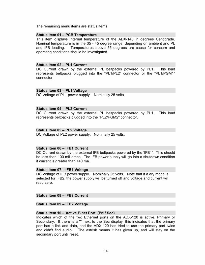
The remaining menu items are status items
Status Item 01 – PCB TemperatureThis item displays internal temperature of the ADX-140 in degrees Centigrade. Nominal temperature is in the 35 - 45 degree range, depending on ambient and PL and IFB loading. Temperatures above 55 degrees are cause for concern andoperating conditions should be investigated.
Status Item 02 – PL1 CurrentDC Current drawn by the external PL beltpacks powered by PL1. This load represents beltpacks plugged into the "PL1/PL2" connector or the "PL1/PGM1" connector.
Status Item 03 – PL1 VoltageDC Voltage of PL1 power supply. Nominally 25 volts.
Status Item 04 – PL2 CurrentDC Current drawn by the external PL beltpacks powered by PL1. This load represents beltpacks plugged into the "PL2/PGM2" connector.
Status Item 05 – PL2 VoltageDC Voltage of PL2 power supply. Nominally 25 volts.
Status Item 06 – IFB1 CurrentDC Current drawn by the external IFB beltpacks powered by the 'IFB1'. This should be less than 100 milliamps. The IFB power supply will go into a shutdown condition if current is greater than 140 ma.
Status Item 07 – IFB1 VoltageDC Voltage of IFB power supply. Nominally 25 volts. Note that if a dry mode is selected for IFB2, the power supply will be turned off and voltage and current will read zero.
Status Item 08 – IFB2 Current
Status Item 09 – IFB2 Voltage
Status Item 10 - Active E-net Port (Pri / Sec)Indicates which of the two Ethernet ports on the ADX-120 is active, Primary or Secondary. If there is a '*' next to the Sec display, this indicates that the primary port has a link and data, and the ADX-120 has tried to use the primary port twice and didn't find audio. The astrisk means it has given up, and will stay on the secondary port until reset.

15
Status Item 11 - Pri Port Status (No Link / Link Only / Link+Data)Indicates the current status of the primary Ethernet port. No Link indicates that there is no Ethernet link to the switch. Link Only means that there is a link to the switch but no packets are being received. Link+Data means that packets are being received which usually indicates Cobranet traffic, but not necessarily audio for this unit (if perhaps it were not assigned at the truck).
Status Item 12 – Sec Port Status (No Link / Link Only / Link+Data)Same as above for the secondary port
Status Item 13 – Firmware VersionDisplay of the version number of the firmware installed in the ADX-140.
Accessing the ADX-140 Menu Via the Remote Connector
The ADX-140 menus are also accessable via the RS-232 port in the Remote Control connector on the rear panel. Although it's unlikely that you would need this function it allows configuration of the unit in a case where it might be operated with Cobranet hardware other than the ADX-2400. We also use it for test purposes in the shop.
The connector has a standard old-fashioned PC modem pinout, and will connect directly to a PC comm port or a USB-Serial adapter. The PC will need to run a generic terminal application (like Hyperlink, or one of the many shareware terminal apps available).
The baud rate is 38.4K, no parity, one stop bit. When the PC is connected, press return, and you'll see the the ADX-140 menus. The space bar will toggle between item select mode and variable set mode. The comma and period keys ('<' and '>') take the place of the knob to step through the items or to change the settings.
16
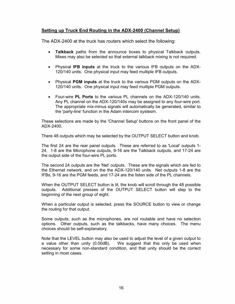
Setting up Truck End Routing in the ADX-2400 (Channel Setup)
The ADX-2400 at the truck has routers which select the following:
Talkback paths from the announce boxes to physical Talkback outputs. Mixes may also be selected so that external talkback mixing is not required.
Physical IFB inputs at the truck to the various IFB outputs on the ADX-120/140 units. One physical input may feed multiple IFB outputs.
Physical PGM inputs at the truck to the various PGM outputs on the ADX-120/140 units. One physical input may feed multiple PGM outputs.
Four-wire PL Ports to the various PL channels on the ADX-120/140 units. Any PL channel on the ADX-120/140s may be assigned to any four-wire port. The appropriate mix-minus signals will automatically be generated, similar to the 'party-line' function in the Adam intercom systesm.
These selections are made by the 'Channel Setup' buttons on the front panel of the ADX-2400.
There 48 outputs which may be selected by the OUTPUT SELECT button and knob.
The first 24 are the rear panel outputs. These are referred to as 'Local' outputs 1-24. 1-8 are the Microphone outputs, 9-16 are the Talkback outputs, and 17-24 are the output side of the four-wire PL ports.
The second 24 outputs are the 'Net' outputs. These are the signals which are fed to the Ethernet network, and on the the ADX-120/140 units. Net outputs 1-8 are the IFBs, 9-16 are the PGM feeds, and 17-24 are the listen side of the PL channels.
When the OUTPUT SELECT button is lit, the knob will scroll through the 48 possible outputs. Additional presses of the OUTPUT SELECT button will step to the beginning of the next group of eight.
When a particular output is selected, press the SOURCE button to view or change the routing for that output.
Some outputs, such as the microphones, are not routable and have no selection options. Other outputs, such as the talkbacks, have many choices. The menu choices should be self-explanatory.
Note that the LEVEL button may also be used to adjust the level of a given output to a value other than unity (0.00dB). We suggest that this only be used when necessary for some non-standard condition, and that unity should be the correct setting in most cases.

17
Reliability Considerations
Since the commentary microphones and communications are typically provided by this system, reliability is of primary concern. The ADX-series products are designed with highest-quality components and conservative ratings so as to be as reliable as possible.
In addition, after manufacture, the ADX products undergo an extensive burn-in process which includes power and thermal cycling to attempt to precipitate out any early-life failures.
Even with these precautions failures are not impossible, and in addition there are other components to the system such as Ethernet switches which must also be considered in evaluating the overall reliability question.
Here are some thoughts on insuring a reliable on-air system:
Provide a spare announce box and headset. This practice has been going on for decades with analog systems, and it's still a good idea. It protects against failure of the ADX-120 and the headset.
Use the ADX-8000 to provide power for the ADX-120s. This unit contains redundant power supplies and will provide highly-reliable power, even in the event of the failure of one of the supplies. The dual supplies also supply redundant power to the switch itself.
Insure a reliable AC power source in the remote location for the ADX units and for the Ethernet switch. If there is any question about the reliability of the AC supply you might consider using a small UPS power supply to provide battery backup. A small 500 watt unit intended for personal computer use will provide an hour or more of operation in the event of power failure.
Use reliable Ethernet hardware such as switches, fiber SFPs, etc. Burn in new switches for a few days before putting them on the air. Keep all Ethernet cables and fiber in good condition.
Many switches have two or more fiber SFP ports available. If the switches support this type of operation (trunking), and most do, two fiber runs could be connected between switches, thus protecting against fiber and SFP failure. The ADX-8000 switches support trunking and are compatible with most generic layer 2 switches.
It is possible to have a fully-redundant network operating in parallel with the primary network. This of course requires two switches at each location, but provides a very high degree of reliability at moderate additional cost. Contact Lance Design for more information about this type of operation.
(continued)

18
ADX-140 Specifications
Microphone Inputs 4 low-impedence balanced. Phantom power available
Preamp Gain (total path) +25dB to +70dB
Freq Response 20-20KHz, +/- 0.5 dB
Microphone Channel EIN >125 dB, bandwidth-limited to 25KHz, at 60dB gain
System Signal/Noise >100 dB below peak level, bandwidth-limited to 25KHz
Distortion <0.05% for Mic/Line and Dry IFB. <0.12% for PL / Wet IFB
Microphone Preamps THAT Corporation 1570 / 5171
A-D and D-A Conversion 24-bit
Digital Processing Dual-core 32-bit dsp
Cobranet Transmission 20-bit uncompressed
Sample Frequency 48 kHz
Path Latency Approx 2.25 Milliseconds on all paths (analog to analog)
IFB 1 Output 2 channel wet RTS-format or single-channel dry +4dB nom.
IFB 2 Output 2 channel wet RTS-format or single-channel dry +4dB nom.
PL Interface at ADX-140 2 channel wet RTS-format. DC current to support 3 beltpacks
PL Interface (Truck End) 4-wire dry +4dBm nominal. 8 assignable 4W Ports
PL Trans-hybrid Loss Greater than 55 dB at 440Hz
Remote Control From ADX-2400 front panel or via RS232 Remote connector
Front Panel Switches System ID two-digit rotary switches
System Addressing Rear panel two-digit rotary switches. Address 01-99
Bundle Numbers Set automatically based on System Address
Power Requirements 48 Volts DC, 255 ma. 420 ma with four RTS/Telex beltpacks.
Power Source 48V on spare Cat5 pairs, and/or AC Line (95-250VAC, 50/60Hz)
Ethernet Interface 100baseT Standard Ethernet (redundant RJ45 ports)
Ethernet Bandwidth Req’d Approximately 8 megabits each direction per ADX-140
Dimensions 19” wide x 9” deep x 1.75” high (1RU) Weight approx. 3.5 lbs
19
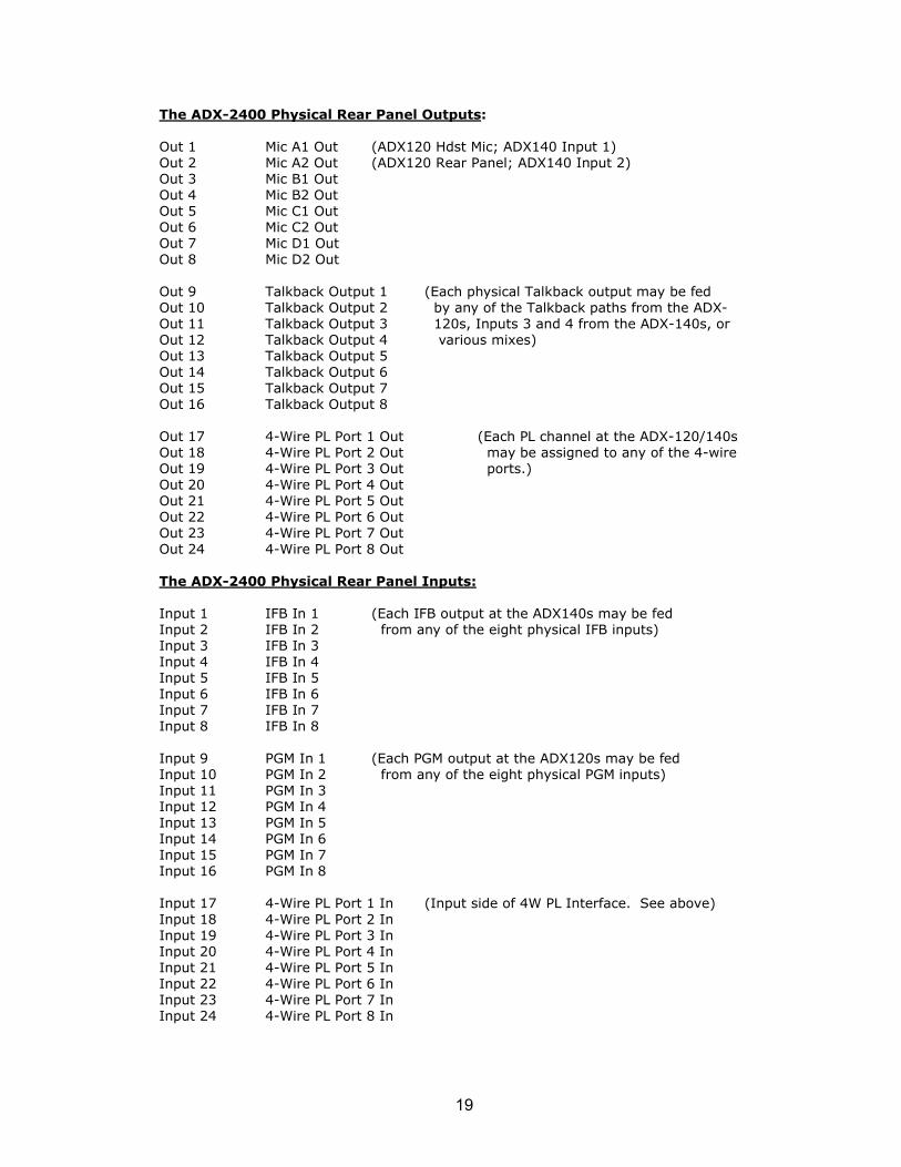
The ADX-2400 Physical Rear Panel Outputs:
Out 1 Mic A1 Out (ADX120 Hdst Mic; ADX140 Input 1)Out 2 Mic A2 Out (ADX120 Rear Panel; ADX140 Input 2)Out 3 Mic B1 OutOut 4 Mic B2 OutOut 5 Mic C1 OutOut 6 Mic C2 OutOut 7 Mic D1 OutOut 8 Mic D2 Out
Out 9 Talkback Output 1 (Each physical Talkback output may be fedOut 10 Talkback Output 2 by any of the Talkback paths from the ADX-Out 11 Talkback Output 3 120s, Inputs 3 and 4 from the ADX-140s, or Out 12 Talkback Output 4 various mixes)Out 13 Talkback Output 5Out 14 Talkback Output 6Out 15 Talkback Output 7Out 16 Talkback Output 8
Out 17 4-Wire PL Port 1 Out (Each PL channel at the ADX-120/140sOut 18 4-Wire PL Port 2 Out may be assigned to any of the 4-wireOut 19 4-Wire PL Port 3 Out ports.)Out 20 4-Wire PL Port 4 OutOut 21 4-Wire PL Port 5 OutOut 22 4-Wire PL Port 6 OutOut 23 4-Wire PL Port 7 OutOut 24 4-Wire PL Port 8 Out
The ADX-2400 Physical Rear Panel Inputs:
Input 1 IFB In 1 (Each IFB output at the ADX140s may be fedInput 2 IFB In 2 from any of the eight physical IFB inputs)Input 3 IFB In 3Input 4 IFB In 4Input 5 IFB In 5Input 6 IFB In 6Input 7 IFB In 7Input 8 IFB In 8
Input 9 PGM In 1 (Each PGM output at the ADX120s may be fedInput 10 PGM In 2 from any of the eight physical PGM inputs)Input 11 PGM In 3Input 12 PGM In 4Input 13 PGM In 5Input 14 PGM In 6Input 15 PGM In 7Input 16 PGM In 8
Input 17 4-Wire PL Port 1 In (Input side of 4W PL Interface. See above)Input 18 4-Wire PL Port 2 InInput 19 4-Wire PL Port 3 InInput 20 4-Wire PL Port 4 InInput 21 4-Wire PL Port 5 InInput 22 4-Wire PL Port 6 InInput 23 4-Wire PL Port 7 InInput 24 4-Wire PL Port 8 In
20
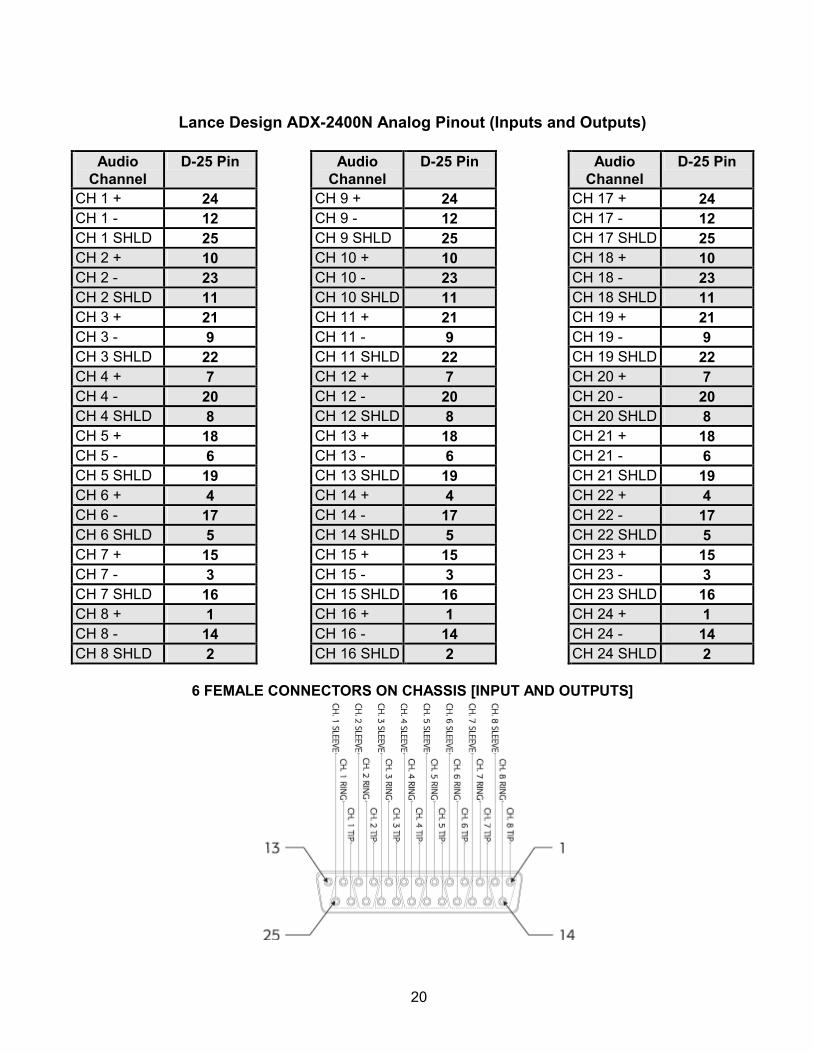
Lance Design ADX-2400N Analog Pinout (Inputs and Outputs)
Audio Channel
D-25 Pin Audio Channel
D-25 Pin Audio Channel
D-25 Pin
CH 1 + 24 CH 9 + 24 CH 17 + 24CH 1 - 12 CH 9 - 12 CH 17 - 12CH 1 SHLD 25 CH 9 SHLD 25 CH 17 SHLD 25CH 2 + 10 CH 10 + 10 CH 18 + 10CH 2 - 23 CH 10 - 23 CH 18 - 23CH 2 SHLD 11 CH 10 SHLD 11 CH 18 SHLD 11CH 3 + 21 CH 11 + 21 CH 19 + 21CH 3 - 9 CH 11 - 9 CH 19 - 9CH 3 SHLD 22 CH 11 SHLD 22 CH 19 SHLD 22CH 4 + 7 CH 12 + 7 CH 20 + 7CH 4 - 20 CH 12 - 20 CH 20 - 20CH 4 SHLD 8 CH 12 SHLD 8 CH 20 SHLD 8CH 5 + 18 CH 13 + 18 CH 21 + 18CH 5 - 6 CH 13 - 6 CH 21 - 6CH 5 SHLD 19 CH 13 SHLD 19 CH 21 SHLD 19CH 6 + 4 CH 14 + 4 CH 22 + 4CH 6 - 17 CH 14 - 17 CH 22 - 17CH 6 SHLD 5 CH 14 SHLD 5 CH 22 SHLD 5CH 7 + 15 CH 15 + 15 CH 23 + 15CH 7 - 3 CH 15 - 3 CH 23 - 3CH 7 SHLD 16 CH 15 SHLD 16 CH 23 SHLD 16CH 8 + 1 CH 16 + 1 CH 24 + 1CH 8 - 14 CH 16 - 14 CH 24 - 14CH 8 SHLD 2 CH 16 SHLD 2 CH 24 SHLD 2
6 FEMALE CONNECTORS ON CHASSIS [INPUT AND OUTPUTS]
21
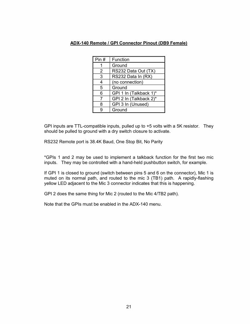
ADX-140 Remote / GPI Connector Pinout (DB9 Female)
Pin # Function1 Ground2 RS232 Data Out (TX)3 RS232 Data In (RX)4 (no connection)5 Ground6 GPI 1 In (Talkback 1)*7 GPI 2 In (Talkback 2)*8 GPI 3 In (Unused)9 Ground
GPI inputs are TTL-compatible inputs, pulled up to +5 volts with a 5K resistor. They should be pulled to ground with a dry switch closure to activate.
RS232 Remote port is 38.4K Baud, One Stop Bit, No Parity
*GPIs 1 and 2 may be used to implement a talkback function for the first two mic inputs. They may be controlled with a hand-held pushbutton switch, for example.
If GPI 1 is closed to ground (switch between pins 5 and 6 on the connector), Mic 1 is muted on its normal path, and routed to the mic 3 (TB1) path. A rapidly-flashing yellow LED adjacent to the Mic 3 connector indicates that this is happening.
GPI 2 does the same thing for Mic 2 (routed to the Mic 4/TB2 path).
Note that the GPIs must be enabled in the ADX-140 menu.

22
NOTES: