Embed Size (px)
Citation preview

1 Copyright © 2012 by ASME
Proceedings of the ASME 2012 International Mechanical Engineering Congress & Exposition IMECE2012
November 9-15, 2012, Houston, Texas, USA
IMECE2012-87856
ADVANTAGES OF AN LQR CONTROLLER FOR STICK-SLIP AND BIT-BOUNCE MITIGATION IN AN OILWELL DRILLSTRING
Md. Mejbahul Sarker Graduate Student
Faculty of Engineering and Applied Science
Memorial University St. John’s, NL, Canada
D. Geoff Rideout Associate Professor
Faculty of Engineering and Applied Science
Memorial University St. John’s, NL, Canada
Stephen D. Butt Professor
Faculty of Engineering and Applied Science
Memorial University St. John’s, NL, Canada
KEYWORDS Drilling, vibration, lumped-segment model, stick-slip, bit-
bounce, bit-rock interaction, linear quadratic regulator, torsion
spring-damper.
ABSTRACT
Failure of oilwell drillstrings is very costly in terms of
money and time. There are many reasons for drillstring failure,
such as vibration, fatigue, and buckling. Stick-slip vibration has
received considerable attention in recent years with increasing
use of polycrystalline diamond compact (PDC) bits in harder
formations, and has motivated extensive research on this type
of drillstring vibration. This paper addresses the advantages of a
linear quadratic regulator (LQR) controller, compared to a
spring-damper isolator, for stick-slip and bit-bounce mitigation
in an oilwell drillstring. A bond graph model of a drillstring has
been used for simulation that predicts axial vibration, torsional
vibration, and coupling between axial and torsional vibration
due to bit-rock interaction.
INTRODUCTION The boreholes of oil exploration and exploitation wells are
typically drilled by means of a rock cutting tool (drill bit),
which is attached at the end of a rather long drill string
consisting of many smaller interconnected drillpipe sections,
and driven by a speed controlled electrical drive. Due to large
lengths and small cross sections of the drilling pipes, low tool
inertia, and emphasized tool vs. rock bed friction, the overall
drillstring electrical drive is prone to poorly damped torsional
vibrations including stick-slip behavior. Stick-slip predominates
when drilling with drag bits (especially with PDC bits) and
stick-slip oscillations induce large cyclic stresses, which may
also excite severe axial and lateral vibrations in the bottom hole
assembly (BHA). This can lead to fatigue problems, reduction
of bit life, unexpected changes in drilling direction, and even
failure of the drillstring. Since drilling is one of the most
expensive operations in oil exploration and development,
vibration control in the oil drilling process is required from an
economic point of view.
In practice, the drilling operator typically controls the
surface-controlled drilling parameters, such as the weight on bit
(WOB), drilling fluid flow through the drill pipe, the drillstring
rotational speed and the density and viscosity of the drilling
fluid to optimize the drilling operations. In particular, the only
means of controlling vibration with current monitoring
technology is to change either the rotary speed or the weight on
bit. Historically, the experience of drillers has revealed that
increasing the rotary speed, decreasing the weight on bit,
modifying the drilling mud characteristics and introducing an
additional friction at the bit etc. are effective strategies to
suppress stick-slip motion [1-6]. Trade-offs must be managed,
however. For example, mitigating stick-slip by reducing
weight on bit might result in a lower rate of penetration.
Increasing rotary speed to reduce stick-slip might bring other
vibration modes into resonance. The effectiveness of ad hoc
changing of drilling parameters is also dependent on the skill of
the operator.
Recently linear quadratic regulator controllers have been
discussed [1, 3] as a means of improving multiple types of
vibration such as stick-slip and bit-bounce motion
simultaneously.
This paper presents the improvements of using an LQR
controller instead of a torsional spring-damper isolator near the
top drive system for stick-slip and bit-bounce mitigation in an
oilwell drillstring. Passive spring-damper isolators must be
tunable given that drillstring properties are a function of its

2 Copyright © 2012 by ASME
length. Non-linear energy sinks (NES) [19, 20] are a potential
means of attenuating vibration over a wide frequency range, but
would likely require physical realization of a large rotary
inertia. In this paper, a bond graph model of an oilwell
drillstring has been used to compare LQR control and a tunable
linear isolator. The model includes a bit-rock interaction
submodel that predicts axial vibration, torsional vibration, and
coupling between axial and torsional vibration.
OILWELL DRILLING SYSTEM MODELING The rotary drilling system being modeled consists of
drillpipes, the drillcollar assembly (made up of heavier collar
pipes) and the drill bit at the end of the collar assembly and the
rock (formation). Drilling fluid is circulated in the drillpipe and
the annular space between the drillpipe and the wellbore. The
drilling fluid is characterized by the flow rate developed by the
mud pumps. The top of the drillstring is subject to a tension
force, applied through the surface cables. Rotary motion is
applied by an armature-controlled motor, through a gear box, to
the rotary table via the kelly (a square, hexagonal or octagonal
shaped tubing that is inserted through and is an integral part of
the rotary table that moves freely vertically while the rotary
table turns it). The essential components of the oilwell drilling
system and the necessary geometry used for the model are
shown in Fig. 1. A lumped-segment approach is used in the
axial and torsional dynamic model. In the lumped segment
approach, the system is divided into number of inertias,
interconnected with springs [7-9]. The accuracy of the model
depends on the number of elements considered; however, in
contrast to a modal expansion approach [7], the analytic model
shapes and natural frequencies need not be determined. Both
axial and torsional submodels have a total of 21 segments to
capture the first eight axial and torsional natural frequencies of
the whole drillstring. A physical schematic of the lumped-
segment models is shown in Fig. 2.
Figure 1: Oilwell drilling system (adapted from [2])
In the axial submodel, hydraulic forces are included at the top
of the drill collar and bottom of the drillstring to capture the
effect of drilling mud density and buoyancy. Hydrodynamic
damping, due to drilling fluid circulation in the drill pipe and
the annular space, is considered in the drill pipe and collar
model [1].
Figure 2: Physical schematic of (a) axial segments and (b) torsional
segments
In the torsional model, the drill pipe and drill collar dynamic
models consider viscous damping which results from the
contact between drillstring surfaces and drilling fluid [1].
A quasi-static rock-bit model, which provides coupling
between axial and torsional drillstring dynamics, is used instead
of a computationally intensive and difficult-to-parameterize
complete dynamic representation. The model equations are
based on the bit-rock model in [3-4], and are discussed in [1].
The bond graph model of the rotary drillstring is shown in
Appendix A. The reader is referred to [1, 7] for more details on
the bond graph modeling method.
LINEAR QUADRATIC REGULATOR A linear quadratic regulator (LQR) has been designed to
control the torsional dynamics of the system. LQR is a well-
known design technique that provides optimal feedback gains.
In order to determine LQR gains, a performance index is
required. A performance index is the integral over time of
several factors which are to intended to be minimized. The
Riccati equation is solved to calculate optimal linear gains. In
order to reduce the dimension of the state vector and to
minimize the number of states that must be physically
measured or estimated, a simplified lumped parameter torsional
model (Fig. 13) is used instead of taking 21 segments. The
overall method of designing a controller using LQR technique
is discussed in [1, 3]. The necessary equations for the controller
design are shown in Appendix B.
In order to design the controller, a five-state (motor
current, rotary table speed, rotary table displacement, drill bit
speed, and bit displacement) simplified model is used. The
resulting controller gains are then applied to the high order
model for simulation. Fig. 14 in Appendix B shows the
controller block diagram connection to the bond graph plant

3 Copyright © 2012 by ASME
model. The control voltage necessary to keep the torsional
vibrations zero while maintaining a desired bit and rotary table
speed is given by
𝑉𝐶 = 𝑉𝑟𝑒𝑓 − 𝐾1𝐼 − 𝐾2 ∅𝑟𝑡 − 𝜔𝑑 ∗ 𝑡 − 𝐾3 ∅ 𝑟𝑡 − 𝜔𝑑 −
𝐾4 ∅𝑟𝑡 − ∅ − 𝐾5(∅ − 𝜔𝑑) (1)
For different drilling depths the gain matrix K is calculated by
using MATLAB and the gains vs. depth curves (Fig. 15) are
shown in Appendix B.
ALTERNATIVE CONTROL SCHEMES In the literature, numerous solutions have been presented
to control stick-slip oscillations, such as robust µ-synthesis
controller [10], H∞ controller [11], genetic algorithm optimized
controller [12], D-OSKIL controller [13], torque estimator-
based controller [14], and modeling error compensation based
controller [15]. Many such controllers have practical
limitations. However, one system that has achieved real-world
acceptance is the soft torque rotary system (STRS) [16-18].
STRS is a torque feedback at the top of the drillstring which
makes the system behave in a “softer” way rather than as a
fixed heavy flywheel, so that the torsional waves arriving at the
surface are absorbed, breaking the harmful cycling motion. The
STRS increases the system damping to the extent that rotational
speeds will not drop to levels where there is a risk of the bottom
hole assembly (BHA) sticking. Therefore, the feedback system,
which acts on the rotary drive’s speed input, modifies the speed
of the motor such that the vibrational energy is optimally
extracted from the drillstring. The effect of this feedback
circuit, in practice fully implemented by electronics, is to
emulate a parallel combination of a torsional spring and damper
in series with an ideal motor as shown in Fig. 3.
Figure 3: (a) Conventional or Normal (no STRS) drilling [18], (b)
STRS schematic [18], (c) STRS virtual mechanical elements [18],
(d) Bond graph model of the STRS virtual elements.
The STRS must be tuned by giving values of Ks (drive
stiffness in Nm/rad) and Cs (drive damping in Nms/rad) [17].
The parameters must change as the drillstring length (and thus
compliance and inertia) increase. For a particular Cs (700
Nms/rad) value the range of possible values of Ks for which
stick slip does not occur has been determined, using the bond
graph system model, for different drilling depths as shown in
Fig. 4. Setting the drive stiffness outside this range will not
mitigate stick-slip.
Figure 4: Drive spring stiffness (Ks) vs. drilling depth curve
for a particular drive damping (Cs = 700 Nms/rad)
SIMULATION RESULTS Table 1 in Appendix A summarizes all relevant parameters
that are used in the simulation. The main objective of the
current simulations is to study the theoretical performance of an
LQR controller compared to a torsional spring-damper (or
virtual spring-damper as in the STRS system) on the mitigation
of stick-slip and bit-bounce vibrations in an oilwell drillstring.
The simulation results for a drilling depth 4200 m, where drill
pipe and collar lengths are 4000 m and 200 m, are shown below
in Figs. 5-8.
Fig. 5 shows the full model simulation results in the case of
conventional drilling when the desired rotary table speed is 15
rad/sec (142 rpm) with 175 kN applied WOB. Though the
motor appears to maintain the rotary table speed as desired, the
bit experiences large speed fluctuations indicative of stick-slip.
Also at the same time the torque at surface experiences large
fluctuations consistent with stick-slip [17-18]. When the input
torque grows sufficiently to overcome static friction and the bit
releases, bit speed approaches the axial vibration critical speed
range that is discussed in [1]. Bit-bounce then occurs as
demonstrated in Fig. 5 where dynamic WOB periodically
becomes zero.
Fig. 6 shows the response of the model when LQR control
is activated at the simulation time of 40 seconds, for the case of
175 kN applied WOB and a desired speed of 15 rad/sec (142
rpm). As can be seen, when LQR controller is active the stick-
slip vibration is controlled and a smooth drilling condition is
achieved. That means the drill bit is rotating with constant
desired speed and the torque at the surface becomes constant.
At the same time the controller eliminates high dynamic force
and bit-bounce, as a result of the axial-torsional coupling at the
bit-rock interface.
1000 1500 2000 2500 3000 3500 4000 4500 5000
500
1000
1500
2000
2500
3000
3500
4000
4500
5000
Drilling depth
Spr
ing
stiff
ness
, k (N
m/ra
d)
Drilling depth vs Spring stiffness Curve
Kmax
Kmin
4 Copyright © 2012 by ASME
Figure 5: High stick-slip vibrations with bit-bounce at 15 rad/sec
(142 rpm) rotary table speed and 175 kN applied WOB
Figure 6: Stick-slip and bit-bounce eliminated by LQR control at
15 rad/sec (142 rpm) table speed and 175 kN applied WOB
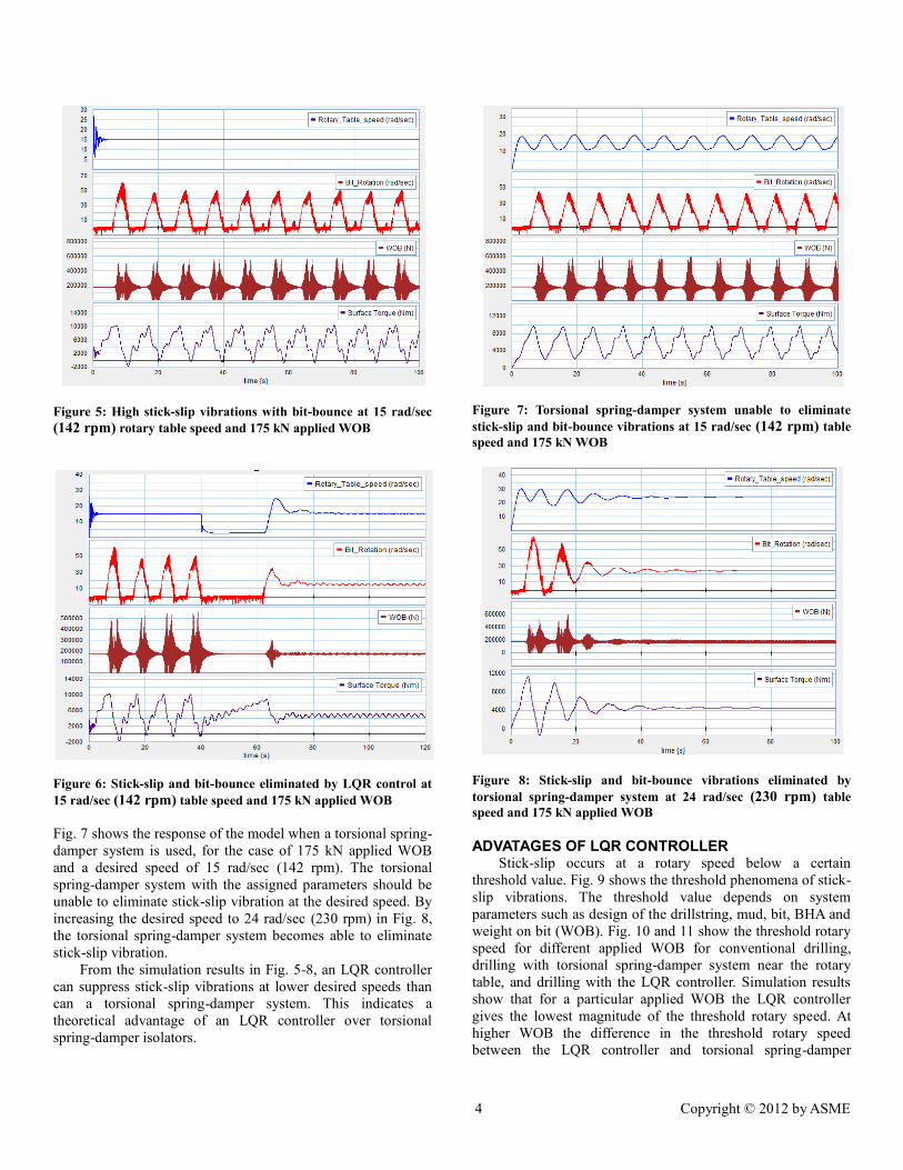
Fig. 7 shows the response of the model when a torsional spring-
damper system is used, for the case of 175 kN applied WOB
and a desired speed of 15 rad/sec (142 rpm). The torsional
spring-damper system with the assigned parameters should be
unable to eliminate stick-slip vibration at the desired speed. By
increasing the desired speed to 24 rad/sec (230 rpm) in Fig. 8,
the torsional spring-damper system becomes able to eliminate
stick-slip vibration.
From the simulation results in Fig. 5-8, an LQR controller
can suppress stick-slip vibrations at lower desired speeds than
can a torsional spring-damper system. This indicates a
theoretical advantage of an LQR controller over torsional
spring-damper isolators.
Figure 7: Torsional spring-damper system unable to eliminate
stick-slip and bit-bounce vibrations at 15 rad/sec (142 rpm) table
speed and 175 kN WOB
Figure 8: Stick-slip and bit-bounce vibrations eliminated by
torsional spring-damper system at 24 rad/sec (230 rpm) table
speed and 175 kN applied WOB
ADVATAGES OF LQR CONTROLLER Stick-slip occurs at a rotary speed below a certain
threshold value. Fig. 9 shows the threshold phenomena of stick-
slip vibrations. The threshold value depends on system
parameters such as design of the drillstring, mud, bit, BHA and
weight on bit (WOB). Fig. 10 and 11 show the threshold rotary
speed for different applied WOB for conventional drilling,
drilling with torsional spring-damper system near the rotary
table, and drilling with the LQR controller. Simulation results
show that for a particular applied WOB the LQR controller
gives the lowest magnitude of the threshold rotary speed. At
higher WOB the difference in the threshold rotary speed
between the LQR controller and torsional spring-damper

5 Copyright © 2012 by ASME
system increases, and it indicates that at higher WOB, and
notwithstanding certain practical implementation issues to be
discussed later, an LQR controller can increase the no stick-slip
zone significantly compared to a torsional spring-damper
system.
Figure 9: Threshold speed for stick-slip vibration
Figure 10: Threshold rotary speed vs. applied WOB curve for
different operating conditions at 2200 m depth.
Figure 11: Threshold rotary speed vs. applied WOB curve for
different operating conditions at 4200 m depth.
During drilling, the LQR controller requires: (i) motor current,
(ii, iii) rotary table rotary speed and displacement, (iv-v) bit
rotary speed and displacement. Except for the bit speed and
displacement, all other quantities in the controller can be
measured. The bit speed measurement (and calculation of bit
rotary displacement through integration) requires downhole
equipment that is expensive and at this point not typically used
in well drilling because the information is not needed if a
controller is not used. Bit speed measurement is the biggest
challenge preventing LQR and other sophisticated controller
implementations, as discussed also in [2-3, 15]. The virtual
spring-damper of the STRS system requires only measurement
of motor current, giving it an economic and implementation
advantage at present. The additional potential benefits of LQR
are expected to motivate drillers to eventually use advanced
downhole measurement tools, to enable such control. The
additional cost of instrumentation would be justified by even
smoother drilling and fewer tool failures.
CONCLUSIONS Self-excited stick-slip oscillations in oilwell drillstrings are
largely suppressed by the application of LQR control.
Therefore, it is possible to drill smoothly at very low speeds
which are otherwise not possible without LQR control. It has
been shown that the advantages of using LQR control increase
with higher applied WOB. The performance of LQR control for
mitigation of stick-slip decreases with increasing depth. It
nonetheless retains an advantage compared to a system with a
spring-damper isolator. This should motivate the use of LQR
controllers in future when practical challenges in measuring
required state variables for LQR control are addressed by
advances in downhole measurement technology. The
implementation of the high-order model in commercial
software that allows block diagrams to be superimposed on
bond graphs greatly facilitated inclusion of the coupled axial
and torsional degrees of freedom due to bit-rock interaction,
along with the controller.
ACKNOWLEDGMENTS This work was done at the Advanced Exploration Drilling
Technology Laboratory at Memorial University in St. john’s,
Canada. Financial support was provided by Husky Energy,
Suncor Energy, Newfoundland and Labrador Research and
Development Corporation, and Atlantic Canada Opportunities
Agency under AIF contract number 781-2636-192044.
NOMENCLATURE 𝐶𝑟𝑡 = Equivalent viscous damping coefficient, N-m-s/rad
𝐼 = Current, A
𝐽 = Drillstring mass moment of inertia, kg-m2
𝐽𝑘 = Inertia of kelly, kg-m2
𝐽𝑚 = Inertia of motor. kg-m2
𝐽𝑟𝑡 = Inertia of rotary table, kg-m2
𝐾𝑚 = Motor constant, V-s
𝐾𝑡 = Torsional stiffness, N-m/rad
𝐿 = Motor inductance, H
0 10 20 30 40 50 60 700
50
100
150
200
250
300
Threshold Rotary speed (rad/sec)
Ap
pli
ed W
OB
,(kN
)
Threshold Rotary Speed vs. Applied WOB Curve
Drilling with
Torsion Spring-Damper
Drilling with
LQR Controller
Conventional
Drilling
Increasing Safe Zone
Stick-slip
Not Present
Zone
Stick-slip
Present
Zone
0 10 20 30 40 50 60 700
50
100
150
200
250
300
Threshold Rotary speed (rad/sec)
Ap
pli
ed W
OB
,(kN
)
Threshold Rotary Speed vs. Applied WOB Curve
Conventional
Drilling
Drilling with
Torsion Spring-Damper
Stick-slip
Not Present
Zone
Increasing Safe Zone
Drilling with
LQR Controller
Stick-slip
Present
Zone

6 Copyright © 2012 by ASME
𝑛 = Gear ratio
𝑅𝑚 = Armature resistance, Ω
𝐶𝑣 = Viscous damping coefficient, N-m-s/rad
∅ 𝑟𝑡 = Rotary table speed, rad/sec
∅𝑟𝑡 = Rotary table angular displacement, rad
REFERENCES [1] Sarker, M.M., Rideout, D.G., & Butt, S.D. (2012)
“Dynamic Model of an Oilwell Drillstring with
Stick-Slip and Bit-Bounce Interaction” Submitted
to 10th
International Conference on Bond Graph
Modeling and Simulation. Genoa, Italy, July 8-11,
2012. The Society for Modeling and Simulation
International, San diego, CA, USA.
[2] Leine, R. I., Van Campen, D. H., & Keultjes, W. J.
G. (2002). Stick-slip Whirl Interaction in
Drillstring Dynamics. Journal of Vibration and
Acoustics, 124(2), 209–220.
[3] Yigit, A. S., & Christoforou, A. P. (2000).
Coupled Torsional and Bending Vibrations of
Actively Controlled Drillstrings. Journal of Sound
Vibration, 234(1), 67–83.
[4] Yigit, A. S., & Christoforou, A. P. (2006). Stick-
slip and Bit-bounce Interaction in Oil-well
Drillstrings. Journal of Energy Resources
Technology, 128(4), 268–274.
[5] Cobern, M. E., & Wassell, M. E. (2004). Drilling
Vibration Monitoring and Control System.
National Gas Technologies II Conference
Phoenix, AZ, 8-11 February.
[6] http://www.slb.com/~/media/Files/drilling/brochu
res/mwd/drilling_dynamics_sensors_opt_br.ashx
[7] Karnoop, D. C., Margolis, D. L., & Rosenberg, R.
C., (1999). System Dynamics; Modeling and
Simulation of Mechatronics Systems, 3rd
ed., John
Wiley & Sons, Inc., New York.
[8] Eronini, I. E., Somerton, W. H., & Auslander, D.
M. (1982). A Dynamic Model for Rotary Rock
Drilling. Journal of Energy Resources Technology,
104(2), 108–120.
[9] Rao, S.S. (1995). Mechanical Vibrations, 3rd
ed.,
Addison-Wesley Publishing Company, New York.
[10] Karkoub, M., Zribi, M., Elchaar, L., & Lamont, L.
(2010). Robust μ-Synthesis Controllers for
Suppressing Stick-slip Induced Vibrations in Oil
Well Drill Strings. Multibody System Dynamics,
23(2), 191–207.
[11] Serrarens, A. F. A., van de Molengraft, M. J. G.,
Kok, J. J., & van den Steen, L. (1998). H∞ Control
for Suppressing Stick-slip in Oil Well Drillstrings.
Control Systems, IEEE, 18(2), 19–30.
[12] Karkoub, M., Abdel-Magid, Y. L., &
Balachandran, B. (2009). Drill-string Torsional
Vibration Suppression Using GA Optimized
Controllers. Journal of Canadian Petroleum
Technology, 48(12), 32–38.
[13] Canudas-de-Wit, C., Rubio, F. R., & Corchero, M.
A. (2008). D-OSKIL: A New Mechanism for
Controlling Stick-slip Oscillations in Oil Well
Drillstrings. IEEE Transactions on Control
Systems Technology, 16(6), 1177–1191.
[14] Pavkovic, D., Deur, J., & Lisac, A. (2011). A
Torque Estimator-based Control Strategy for Oil-
well Drill-string Torsional Vibrations Active
Damping Including an Auto-tuning Algorithm.
Control Engineering Practice, 19(8), 836–850.
[15] Puebla, H., & Alvarez-Ramirez, J. (2008).
Suppression of Stick-slip in Drillstrings: A
Control Approach Based on Modeling Error
Compensation. Journal of Sound and Vibration,
310(4-5), 881–901.
[16] Womer, K. A., Torkay, D. R., Villanueva, G. P.,
Geehan, T., Brakel, J., Pirovolou, D., et al. (2011).
Results of July 15, 2010 IADC Stick-Slip
Mitigation Workshop. SPE/IADC Drilling
Conference and Exhibition. Amsterdam, The
Netherlands: Society of Petroleum Engineers.
[17] http://www.softtorque.com
[18] Kriesels, P. C., Keultjes, W. J. G., Dumont, P.,
Huneidi, I., Owoeye, O. O., & Hartmann, R. A.
(1999). Cost Savings through an Integrated
Approach to Drillstring Vibration Control.
SPE/IADC Middle East Drilling Technology
Conference. Abu Dhabi, United Arab Emirates:
Society of Petroleum Engineers.
[19] Younesian, D. et al. (2010). Application of the
Nonlinear Energy Sink Systems in Vibration
Suppression of Railway Bridges. Proc. ASME
10th
Biennial Conf. on Eng. Sys. Design and
Analysis, July 12-14, Istanbul, Turkey.
[20] Ahmadabadi, Z. N., and Khadem, S.E. (2012).
Nonlinear vibration control of a cantilever beam
by a nonlinear energy sink. Mech. and Machine
Theory 50, pp. 134-149.

7 Copyright © 2012 by ASME
APPENDIX A
ROTARY DRILLING SIMULATION MODEL AND DATA
Figure 12: Bond graph model of rotary drilling system
Table 1: Data used in rotary drilling simulation
Drillstring data Cable and derrick spring constant 9.3e+06 N/m
Swivel and derrick mass 7031 kg
Kelly length 15 m
Kelly outer diameter 0.379 m
Kelly inner diameter 0.0825 m
Drill pipe outer diameter 0.101 m (4 in)
Drill pipe inner diameter 0.0848 m (3.34 in)
Drill collar length 200 m
Drill collar outer diameter 0.171 m (6.75 in)
Drill collar inner diameter 0.0571 m (2.25 in)
Drill string material Steel
Wellbore diameter 0.2 m
Drill bit-rock data
Bit type PDC (Single cutter)
Drill bit diameter 0.2 m (7.875 in)
Drill bit mass 65 kg
Rock stiffness 1.16e+09 N/m
Rock damping 1.5e+05 N.sec/m
Surface elevation amplitude 𝑠0 0.001
Bit factor, b 1
Cutting coefficient ξ, 𝐶1, 𝐶2 1, 1.35e-08, -1.9e-4
Frictional coefficient 𝜇0, 𝛼,β, 𝛾 & 𝜈 0.06, 2, 1, 1 & 0.01
Threshold force, 𝑊𝑓𝑠 10000 N
Hydraulic data
Mud fluid density, ρm 1198 kg/m3
Mud flow rate, Q 𝑄𝑚 + 𝑄𝑎 sin(𝑞𝑡)
Mean mud flow rate, 𝑄𝑚 0.022 m3/sec
Mud flow pulsation amplitude, 𝑄𝑎 0.002 m3/sec
Freq. of variation in mud flowrate, q 25.13 rad/sec
Equivalent fluid viscosity for fluid
resistance to rotation 𝜇𝑒
30e-03 Pa.sec
Weisbach friction factor outside drill
pipe or collar, 𝛼𝑎
0.045
Weisbach friction factor inside drill
pipe or collar, 𝛼𝑝
0.035
Motor data
L, 𝐾𝑚 , n and Rm, 0.005 H, 6 V/s, 7.2
and 0.01 Ω
Rock-Bit Model
Torsional Dynamic ModelAxial Dynamic Model
0
0
0
MSe
TOB
1
Rotary_Table
R
Rotary_damping
C
Rock_C
R
Resistance
Axial
Pipe_axial9
Axial
Pipe_axial8
Axial
Pipe_axial7
Axial
Pipe_axial6
Axial
Pipe_axial5
Axial
Pipe_axial4
Axial
Pipe_axial3
Axial
Pipe_axial2
Axial
Pipe_axial1
Axial
Pipe_axial
1
1
1
1
I
Motor_inductance
GY
Motor_constant
1
Motor
Torsion
Kelly_Table_Motor_Inertia
Axial
Swiv el
Kelly_Swivel
Integrate
Se
Input_Voltage
TF
Gear_Ratio
MSf
Flow_Excitation
Sf
Fixed_support
Se
F2_Hydraulic
Torsion
DrillPipe_Tor9
Torsion
DrillPipe_Tor8
Torsion
DrillPipe_Tor7
Torsion
DrillPipe_Tor6
Torsion
DrillPipe_Tor5
Torsion
DrillPipe_Tor4
Torsion
DrillPipe_Tor3
Torsion
DrillPipe_Tor2
Torsion
DrillPipe_Tor1
Torsion
DrillPipe_Tor
Torsion
DrillCollar_Tor9
Torsion
DrillCollar_Tor8
Torsion
DrillCollar_Tor7
Torsion
DrillCollar_Tor6
Torsion
DrillCollar_Tor5
Torsion
DrillCollar_Tor4
Torsion
DrillCollar_Tor3
Torsion
DrillCollar_Tor2
Torsion
DrillCollar_Tor1
Torsion
DrillCollar_Tor
Cosine
Axial
Collar_axial9
Axial
Collar_axial8
Axial
Collar_axial7
Axial
Collar_axial6
Axial
Collar_axial5
Axial
Collar_axial4
Axial
Collar_axial3
Axial
Collar_axial2
Axial
Collar_axial1
Axial
F1
Collar_axial
C
Cable_derrick_C
R
Cable_Damping
Se
Bit_Weight
1Bit_Rotation
IBit_Mass
I
Bit_Inertia

8 Copyright © 2012 by ASME
APPENDIX B
LQR CONTROL MODEL DESIGN AND GAINS CURVES
CONTROLLER EQUATIONS The state space equation of the simplified model in Fig. 11
is
𝑿 = 𝑨𝑿 + 𝑩𝑽𝑪 (16)
where X, A, and B are the state vector, coefficient, and input
matrices, respectively:
𝐴 =
−
𝑅𝑚
𝐿0 −
𝑛𝐾𝑚
𝐿0 0
0 0 1 0 0𝑛𝐾𝑚
𝐽𝑘+𝐽𝑟𝑡 +𝑛2𝐽𝑚0
−𝐶𝑟𝑡
𝐽𝑘+𝐽𝑟𝑡 +𝑛2𝐽𝑚
−𝐾𝑡
𝐽𝑘+𝐽𝑟𝑡 +𝑛2𝐽𝑚0
0 0 1 0 −1
0 0 0𝐾𝑡
𝐽
−𝐶𝑣
𝐽
(17)
𝑋𝑇 = [ 𝐼 ∅𝑟𝑡 ∅ 𝑟𝑡 ∅𝑟𝑡 − ∅ ∅ ] (18)
BT = [ 1
𝐿0 0 0 0 ] (19)
The performance index:
𝐶 =1
2 (𝑥𝑇𝑄𝑥 + 𝑟𝑉𝐶
2)∝
0𝑑𝑡 (20)
The resulting optimal control input (rotary table motor voltage)
can be written as
𝑉𝐶 = 𝑉𝑟𝑒𝑓 − 𝐾(𝑥 − 𝑥𝑑) (21)
The gain matrix, K can be written as
𝐾 = 𝑟−1 𝐵𝑇𝑃 (22) The algebraic Riccati equation is given by
𝐴𝑇𝑃 + 𝑃𝐴 − 𝑟−1𝑃𝐵𝐵𝑇𝑃 + 𝑄 = 0 (23)
The chosen r and Q are
𝑟 = 950 (25)
𝑄 =
1 0 0 0 00 20000 0 0 00 0 1 0 00 0 0 80000 00 0 0 0 950000
(26)
(a)
(b)
Figure 13: (a) Physical schematic of model used for control design.
(b) Bond graph torsional model using simplified lumped
parameter model
Figure 14: LQR controller block diagram connection to the bond
graph plant model.
Motor Constant
1/n
Gear box
Jrt + n^ Jm
0
0
C
Torsion_comp
MSe
TOB
TF
I
Se
Vc_Input_Voltage
1
Rotary_Table
R
Rotary_damping
R
Resistance
1
I
Motor_inductance
1
Motor
GY
Km
R
Damping
I
J_torsion
1
DrillBit_Rotation
Axial
Model
Torsional
Model
C
Rock_C
0MSe
TOB
TF
TF
Rotary_Table_Dis
1
Rotary_Table
R
Rotary_damping
R
Resistance
1
1 MSf
MSf
I
Motor_inductance
1 MotorTorsion
Kelly_Table_Motor_Inertia
P
K5
P
K4
P
K3
P
K2
P
K1
Integrate
MSe
Input_Voltage
GY
GY
Torsion
DrillCollar_Tor9
Desired_table_speed
Desired_Rotar_Dis1
Cosine
1
Bit_Rotation
Bit_Rotar_Dis
I
Bit_Inertia1

9 Copyright © 2012 by ASME
Figure 15: Gains vs. depth curves for LQR controller
1000 1500 2000 2500 3000 3500 4000 4500 50000.025
0.026
0.027
0.028
0.029
0.03
0.031
0.032
0.033
0.034
Depth (m)
Gain
, K
1
1000 1500 2000 2500 3000 3500 4000 4500 50004.4
4.45
4.5
4.55
4.6
4.65
4.7
4.75
4.8
Depth (m)
Gain
, K
2
1000 1500 2000 2500 3000 3500 4000 4500 50001
1.5
2
2.5
3
3.5
4
Depth (m)
Gain
, K
3
1000 1500 2000 2500 3000 3500 4000 4500 500020
30
40
50
60
70
Depth (m)
Gain
, K
4
1000 1500 2000 2500 3000 3500 4000 4500 50007.5
8
8.5
9
9.5
10
10.5
11
11.5
12
12.5
Depth (m)
Gai
n, K
5