Embed Size (px)
Citation preview
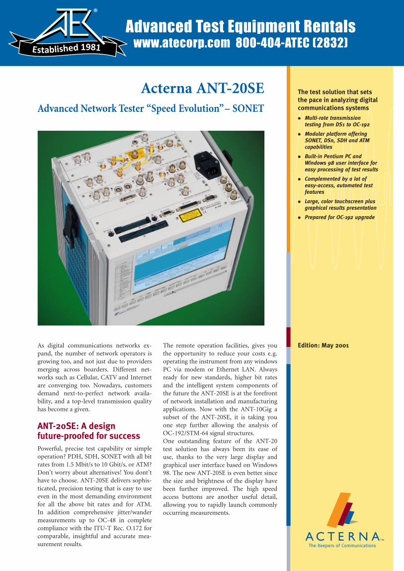
Acterna ANT-20SEAdvanced Network Tester ªSpeed Evolutionº± SONET
As digital communications networks ex-pand, the number of network operators isgrowing too, and not just due to providersmerging across boarders. Different net-works such as Cellular, CATV and Internetare converging too. Nowadays, customersdemand next-to-perfect network availa-bility, and a top-level transmission qualityhas become a given.
ANT-20SE: A designfuture-proofed for successPowerful, precise test capability or simpleoperation? PDH, SDH, SONET with all bitrates from 1.5 Mbit/s to 10 Gbit/s, or ATM?Don't worry about alternatives! You dont'thave to choose. ANT-20SE delivers sophis-ticated, precision testing that is easy to useeven in the most demanding environmentfor all the above bit rates and for ATM.In addition comprehensive jitter/wandermeasurements up to OC-48 in completecompliance with the ITU-T Rec. O.172 forcomparable, insightful and accurate mea-surement results.
The remote operation facilities, gives youthe opportunity to reduce your costs e.g.operating the instrument from any windowsPC via modem or Ethernet LAN. Alwaysready for new standards, higher bit ratesand the intelligent system components ofthe future the ANT-20SE is at the forefrontof network installation and manufacturingapplications. Now with the ANT-10Gig asubset of the ANT-20SE, it is taking youone step further allowing the analysis ofOC-192/STM-64 signal structures.One outstanding feature of the ANT-20test solution has always been its ease ofuse, thanks to the very large display andgraphical user interface based on Windows98. The new ANT-20SE is even better sincethe size and brightness of the display havebeen further improved. The high speedaccess buttons are another useful detail,allowing you to rapidly launch commonlyoccurring measurements.
The test solution that setsthe pace in analyzing digitalcommunications systems
. Multi-rate transmissiontesting from DS1 to OC-192
. Modular platform offeringSONET, DSn, SDH and ATMcapabilities
. Built-in Pentium PC andWindows 98 user interface foreasy processing of test results
. Complemented by a lot ofeasy-access, automated testfeatures
. Large, color touchscreen plusgraphical results presentation
. Prepared for OC-192 upgrade
Edition: May 2001
Advanced Test Equipment Rentalswww.atecorp.com 800-404-ATEC (2832)
®
Established 1981
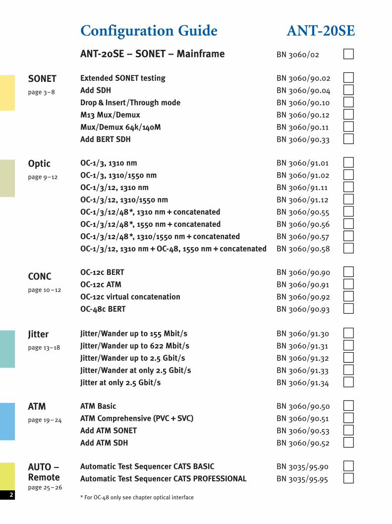
Configuration Guide ANT-20SE
ANT-20SE ± SONET ± Mainframe BN 3060/02 &
Extended SONET testing BN 3060/90.02 &Add SDH BN 3060/90.04 &Drop & Insert/Through mode BN 3060/90.10 &M13 Mux/Demux BN 3060/90.12 &Mux/Demux 64k/140M BN 3060/90.11 &Add BERT SDH BN 3060/90.33 &
OC-1/3, 1310 nm BN 3060/91.01 &OC-1/3, 1310/1550 nm BN 3060/91.02 &OC-1/3/12, 1310 nm BN 3060/91.11 &OC-1/3/12, 1310/1550 nm BN 3060/91.12 &OC-1/3/12/48*, 1310 nm + concatenated BN 3060/90.55 &OC-1/3/12/48*, 1550 nm + concatenated BN 3060/90.56 &OC-1/3/12/48*, 1310/1550 nm + concatenated BN 3060/90.57 &OC-1/3/12, 1310 nm + OC-48, 1550 nm + concatenated BN 3060/90.58 &
OC-12c BERT BN 3060/90.90 &OC-12c ATM BN 3060/90.91 &OC-12c virtual concatenation BN 3060/90.92 &OC-48c BERT BN 3060/90.93 &
Jitter/Wander up to 155 Mbit/s BN 3060/91.30 &Jitter/Wander up to 622 Mbit/s BN 3060/91.31 &Jitter/Wander up to 2.5 Gbit/s BN 3060/91.32 &Jitter/Wander at only 2.5 Gbit/s BN 3060/91.33 &Jitter at only 2.5 Gbit/s BN 3060/91.34 &
ATM Basic BN 3060/90.50 &ATM Comprehensive (PVC + SVC) BN 3060/90.51 &Add ATM SONET BN 3060/90.53 &Add ATM SDH BN 3060/90.52 &
Automatic Test Sequencer CATS BASIC BN 3035/95.90 &Automatic Test Sequencer CATS PROFESSIONAL BN 3035/95.95 &
* For OC-48 only see chapter optical interface2
SONETpage 3±8
Opticpage 9±12
CONCpage 10 ±12
Jitterpage 13±18
ATMpage 19±24
AUTO ±Remotepage 25±26
Specifications ANT-20SE SONETANT-20SE Mainframe BN 3060/02
Includes:. Generator and analyzer for electrical STS-1 and STS-3 signals
allowing:± Simulation and evaluation in the TOH / POH± Generation and analysis of Anomalies and Defects± Pointer generator and analyzer
. Generator and analyzer for bit error rate tests (BERT) at6 Mbit/s with unframed, 1.5 and 45 Mbit/s with framed andunframed test patterns
. VT1.5 mapping (DS1 in STS-1)
. Touchscreen
. 4 extension slots
. Ethernet and USB Interface
Generator unit
Digital outputsInterfaces to Telcordia GR-253, TR-TSY-000499, ANSI T1.10275 O coaxial output, adapter jack selectable from Versacon 9 adaptersystemBit rates and line codesDS1 . . . . . . . . . . . . . . . . . . . . . . . . . . . . . . 1544 kbit/s; B8ZS, AMI, CMIDS2 . . . . . . . . . . . . . . . . . . . . . . . . . . . . . . . . . . . 6312 kbit/s; B8ZS, CMIDS3 . . . . . . . . . . . . . . . . . . . . . . . . . . . . . . . . . . 44 736 kbit/s; B3ZS, CMISTS-1 . . . . . . . . . . . . . . . . . . . . . . . . . . . . . . . . 51 840 kbit/s; B3ZS, CMISTS-3 . . . . . . . . . . . . . . . . . . . . . . . . . . . . . . . . . . . . 155 520 kbit/s; CMI
100 O balanced output, Bantam jackBit rate and line codesDS1 . . . . . . . . . . . . . . . . . . . . . . . . . . . . . . 1544 kbit/s; B8ZS, AMI, CMIOutput pulsesDS1 . . . . . . . . . . . . . . . . . . . . . . . . . . . . . . . . . . . . . . . DSX-1 compatibleDS2 . . . . . . . . . . . . . . . . . . . . . . . . . . . . . . . . . . . . . . . . . . . . . rectangularDS3, STS-1 . . . . . . . . . . . . . . . . . . . . . . . . . . . . . . . HIGH, LOW, DSX-3
Bit rate offset. . . . . . . . . . . . . . . . . . . . . . . . . . . . . . . . . . . . . . +500 ppmStep size . . . . . . . . . . . . . . . . . . . . . . . . . . . . . . . . . . . . . . . . . 0.001 ppm
ClockInternal clock generationat all of the bit rates listed above.Clock stability . . . . . . . . . . . . . . . . . . . . . . . . . . . . . . . . . . . . . . +2 ppm
Synchronisation to external signalsvia 100 O balanced input, Bantam jack:± Reference clock . . . . . . . . . . . . . . . . . . . 1544 kHz and 2048 kHz± 1544 kbit/s (B8ZS), 2048 kbit/s (HDB3) or± Receive signal
Clock outputs± Clock output at frequency of generator signal, approx. 400 mV
(when terminated into 75 O), BNC jack.
STS-3 output signalGeneration of a STS-3 signal conforming to Telcordia GR-253,ANSI T1.105The STS-3 signal consists of one internal STS-1 tributary signal withthe remaining two tributaries filled with UNEQ.
STS-1 output signalGeneration of a STS-1 signal conforming to Telcordia GR-253,ANSI T1.105a
MappingsVT1.5 mapping is included in the basic instrument. Other mappingsare added with option ªExtended SONET testingº.Content of the selected tributary:± Framed or unframed DS1 or DS3 test pattern± M13 multiplex signal (with M13 MUX/DEMUX option)± External DS1 or DS3 signal (with D&I option)± Test pattern without stuffing bits (bulk signal to O.181)Content of non-selected tributaries . . . . . . . . . . . . . framed PRBS 211±1The various mappings are described along with the options.
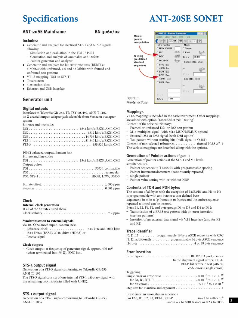
Generation of Pointer actions (figure 1)Generation of pointer actions at the STS-1 and VT levelssimultaneously.± Pointer sequences to T1.105.03 with programmable spacing± Pointer increment/decrement (continuously repeated)± Single pointer± Pointer value setting with or without NDF
Contents of TOH and POH bytesThe content of all bytes with the exception of B1/B2/B3 and H1 to H4is programmable with any byte or a user defined byte-sequence p in m in n (p frames in m frames and the entire sequencerepeated n times) can be inserted.Bytes E1, E2, F1, F2, and byte groups D1 to D3 and D4 to D12:± Transmission of a PRBS test pattern with bit error insertion
(see test patterns)± Insertion of an external data signal via V.11 interface (also for K1
and K2)
Trace identifierJ0, J1, J2 . . . . . . . . . . programmable 16 byte ASCII sequence with CRCJ1, J2, additionally . . . . . . . . . . . programmable 64 byte ASCII sequenceH4 byte . . . . . . . . . . . . . . . . . . . . . . . . . . . . . . . . . 4 or 48 byte sequence
Error insertionError types . . . . . . . . . . . . . . . . . . . . . . . . . . . . . B1, B2, B3 parity errors,
frame alignment signal errors, REI-L,REI-P, bit errors in test pattern,
code errors (single errors)TriggeringSingle error or error ratio . . . . . . . . . . . . . . . . . . . 2610±3 to 1610±10
for B1, B3, REI-P . . . . . . . . . . . . . . . . . . . . . . . . 2610±4 to 1610±10
for bit errors . . . . . . . . . . . . . . . . . . . . . . . . . . . . . 1610±2 to 1610±9
Step size for mantissa and exponent . . . . . . . . . . . . . . . . . . . . . . . . . . . 1
Burst error: m anomalies in n periodsFor FAS, B1, B2, B3, REI-L, REI-P . . . . . . . . . . . . . . m = 1 to 4.866106
and n = 2 to 8001 frames or 0.2 s to 600 s 3
Manualpointermanipulation
or usingpre-definedstandardsequences
Figure 1:Pointer actions.
Alarm generation, dynamicAlarm types . . . . . . . . . . . . . . . . . . . . LOS, LOF, AIS-L, RDI-L, LOP-P,
AIS-P, UNEQ-P, PLM-P, RDI-P, RDIEPP,RDIEPS, RDIEPC, PDI-P
m alarms in n frames . . . . . . . . . . . . . . . . . . m = 1 to n ±1, nmax = 8000ort1 alarm active,t2 alarm passive . . . . . . . . . . . . . . . . . . . . . t1 = 0 to 60 s, t2 = 0 to 600 s
Alarm generation, static (on/off)Alarm types . . . . . . . . . . . . . . . . . . . . LOS, LOF, AIS-L, TIM-L, RDI-L,
LOP-P, AIS-P, UNEQ-P, PLM-P, TIM-P,RDI-P, RDIEPP, RDIEPS, RDIEPC, PDI-P
DS1, DS2 and DS3 output signalsSignal structures± Unframed test pattern± Framed test pattern (only DS1, DS3)DS1 frame structure . . . . . . . . . . . . . . . . . . . . . . . . . . . . . . . . . . SF, ESFDS3 frame structure . . . . . . . . . . . . . . . . . . . . . . . . . . . . . . M13, C parity
Error insertionBit errors in test pattern . . . . . . . . . . . . . . . . . . . .error rate, single errorBPV . . . . . . . . . . . . . . . . . . . . . . . . . . . . . . . . . . . . . . . . . . . . . single errorDS1 F bit (LOF) . . . . . . . . . . . . . . . . . . single error, 2 in 4, 2 in 5, 2 in 6CRC-6 (ESF) . . . . . . . . . . . . . . . . . . . . . . . . . . . . single error, error rateDS3 F bit (LOF) . . . . . . . . . . . single error, 2 in 2, 2 in 3, 3 in 3, 3 in 15,
3 in 16, 3 in 17P parity, CP parity, FEBE . . . . . . . . . . . . . . . . . . . single error, error rateError rate . . . . . . . . . . . . . . . . . . . . . . . . . . . . . . . . . 1610± 2 to 2610± 9
Alarm insertionDS1 . . . . . . . . . . . . . . . . . . . . . . . . . . . . . . . . . . . . . . LOF, AIS, YELLOWDS3 . . . . . . . . . . . . . . . . . . . . . . . . . . . LOF, AIS, YELLOW, IDLE, FEAC
FEAC Far-End Alarm and Control SignalsTo test that FEAC alarm and status information is correctlytransmitted, the relevant signal codes can be selected and inserted intothe DS3 C-bit frame format.
Test patterns
Pseudo-random bit sequencesPRBS: 211±1, 215±1, 220±1, QRSS 20, 211±1 inv., 215±1 inv., 220±1 inv.,223±1 inv.
Programmable wordLength . . . . . . . . . . . . . . . . . . . . . . . . . . . . . . . . . . . . . . . . . . . . . . 16 bits
Receiver unit
Digital inputsInterfaces to . . . . . . . Telcordia GR-253, TR-TSY-000499, ANSI T1.10275 O coaxial input; adapter jack selectable from Versacon 9 adaptersystemBit rates and line codesDS1 . . . . . . . . . . . . . . . . . . . . . . . . . . . . . . 1544 kbit/s; B8ZS, AMI, CMIDS2 . . . . . . . . . . . . . . . . . . . . . . . . . . . . . . . . . . . 6312 kbit/s; B8ZS, CMIDS3 . . . . . . . . . . . . . . . . . . . . . . . . . . . . . . . . . 44 736 kbit/s; B3ZS, CMISTS-1 . . . . . . . . . . . . . . . . . . . . . . . . . . . . . . . . 51 840 kbit/s; B3ZS, CMISTS-3 . . . . . . . . . . . . . . . . . . . . . . . . . . . . . . . . . . . . 155 520 kbit/s; CMI
100 O balanced input, Bantam jackBit rate and line codesDS1 . . . . . . . . . . . . . . . . . . . . . . . . . . . . . . .1544 kbit/s; B8ZS, AMI, CMI
Input levelsDS1 . . . . . . . . . . . . . . . . . . . . . . . . . . . . . . . . . . . . . . . DSX-1 compatibleDS3, STS-1 . . . . . . . . . . . . . . . . . . . . . . . . . . . . . . . HIGH, LOW, DSX-3Clock recovery pulling range . . . . . . . . . . . . . . . . . . . . . . . . . +500 ppm
Selectable input gain, CMI coded . . . . . . . . . . . . . . . . . . . . . 15 to 23 dBB3ZS, B8ZS, HDB3, AMI coded . . . . . . . . . . . . . . . . . . . . . . 15 to 26 dB
Selectable adaptive equalizers for DS3, STS-1. . . . . . . . . . . . . . . . . 450 ftDS1 . . . . . . . . . . . . . . . . . . . . . 1310 ft
Monitor input for STS-3 and STS-12 NRZ signalsSee chapter Optical Interfaces for details.
STS-3 receive signal(for signal structure, see under generator unit)The ANT-20 demultiplexes one selectable STS-1 tributary from STS-3and feeds it to the internal processor for evaluation.
STS-1, DS1 and DS3 receive signalsSignal structures as for generator unit
Trigger output75 O BNC connector, HCMOS signal levelPulse output for received bit errors, transmit frame trigger, transmitpattern trigger or 2048 kHz reference clock
Included mapping
VT1.5 and STM-0 mappingDS1 in STS-1 and 1.5 Mbit/s in STM-0Modes . . . . . . . . . . . . . . . . asynchronous, byte synchronous (floating)Error insertion and measurementAdditional error types . . . . . . . . . . . . . . . . . . . . . . . . . . . . BIP-V, REI-VAlarm generation, dynamicAlarm types. . . . . . . . . . . . . . . . LOP-V, AIS-V, LOM, UNEQ-V, RDI-V,
RDIEVP, RDIEVS, RDIEVC, RFI-V, PDI-V, PLM-Vm alarms in n frames . . . . . . . . . . . . . . . . . . m = 1 to n ±1, nmax = 8000ort1 alarm active,t2 alarm passive . . . . . . . . . . . . . . . . . . . . . t1 = 0 to 60 s, t2 = 0 to 600 s
Alarm generation, static (on/off) and evaluationAlarm types . . . . . . . . . . . . . . . . . . . . . . . . . . . . . . LOP-V, AIS-V, LOM,
UNEQ-V, PLM-V, TIM-V, RDI-V, RDIEVP,RDIEVS, RDIEVC, RFI-V
Alarm detection only . . . . . . . . . . . . . . . . . . . . . . . . . . . . . . . . . . NDF-V
Automatic modes
AutoconfigurationAutomatically sets the ANT-20 to the input signal. The routine searchesat the electrical and optical interfaces for the presence of standardasynchronous and STS-N/OC-N signals (GR-253, ANSI T1.102) andthe payload contents in channel 1.
Automatic SCAN functionThe SCAN function permits sequential testing of all VT1.5 orVT2 channels in a SONETsignal. The ANT-20SE receiver checks foralarms in the receive signal, the SONETstructure and all channels andfor synchronization of the selected test pattern in all channels. Theresults (OK/not OK) for each channel are entered in a matrix. Thegenerator runs simultaneously and can be used to stimulate the deviceunder test.4
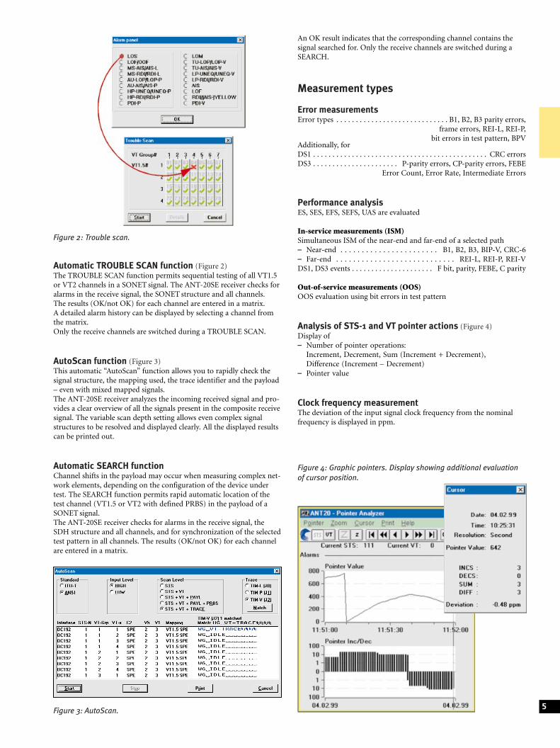
Automatic TROUBLE SCAN function (Figure 2)The TROUBLE SCAN function permits sequential testing of all VT1.5or VT2 channels in a SONET signal. The ANT-20SE receiver checks foralarms in the receive signal, the SONET structure and all channels.The results (OK/not OK) for each channel are entered in a matrix.A detailed alarm history can be displayed by selecting a channel fromthe matrix.Only the receive channels are switched during a TROUBLE SCAN.
AutoScan function (Figure 3)This automatic ªAutoScanº function allows you to rapidly check thesignal structure, the mapping used, the trace identifier and the payload± even with mixed mapped signals.The ANT-20SE receiver analyzes the incoming received signal and pro-vides a clear overview of all the signals present in the composite receivesignal. The variable scan depth setting allows even complex signalstructures to be resolved and displayed clearly. All the displayed resultscan be printed out.
Automatic SEARCH functionChannel shifts in the payload may occur when measuring complex net-work elements, depending on the configuration of the device undertest. The SEARCH function permits rapid automatic location of thetest channel (VT1.5 or VT2 with defined PRBS) in the payload of aSONET signal.The ANT-20SE receiver checks for alarms in the receive signal, theSDH structure and all channels, and for synchronization of the selectedtest pattern in all channels. The results (OK/not OK) for each channelare entered in a matrix.
An OK result indicates that the corresponding channel contains thesignal searched for. Only the receive channels are switched during aSEARCH.
Measurement types
Error measurementsError types . . . . . . . . . . . . . . . . . . . . . . . . . . . . . B1, B2, B3 parity errors,
frame errors, REI-L, REI-P,bit errors in test pattern, BPV
Additionally, forDS1 . . . . . . . . . . . . . . . . . . . . . . . . . . . . . . . . . . . . . . . . . . . . . CRC errorsDS3 . . . . . . . . . . . . . . . . . . . . . . P-parity errors, CP-parity errors, FEBE
Error Count, Error Rate, Intermediate Errors
Performance analysisES, SES, EFS, SEFS, UAS are evaluated
In-service measurements (ISM)Simultaneous ISM of the near-end and far-end of a selected path± Near-end . . . . . . . . . . . . . . . . . . . . . . . B1, B2, B3, BIP-V, CRC-6± Far-end . . . . . . . . . . . . . . . . . . . . . . . . . . . . REI-L, REI-P, REI-VDS1, DS3 events . . . . . . . . . . . . . . . . . . . . . F bit, parity, FEBE, C parity
Out-of-service measurements (OOS)OOS evaluation using bit errors in test pattern
Analysis of STS-1 and VT pointer actions (Figure 4)Display of± Number of pointer operations:
Increment, Decrement, Sum (Increment + Decrement),Difference (Increment ± Decrement)
± Pointer value
Clock frequency measurementThe deviation of the input signal clock frequency from the nominalfrequency is displayed in ppm.
5Figure 3: AutoScan.
Figure 4: Graphic pointers. Display showing additional evaluationof cursor position.
Figure 2: Trouble scan.
Delay measurementDelay measurements are used for aligning satellite hops and testing themaximum permitted delay times for storage exchange and cross-con-nect systems and for checking the loop circuits in regenerators.The ANT-20SE measures the time taken to transmit the test patternfrom the generator through the section under test and back to thereceiver. The measurement is made on the test patterns in a selectedchannel, or in the tributaries (SONET; bulk signal or asynchronous),or on the selected channel of the lowest hierarchy level of asynchronousmultiplex systems.To avoid ambiguities in the measurement, two measurement times areprovided.
Measurement rangeBit rates from 34 to 155 Mbit/s . . . . . . . . . . . . . . . . . . . . . . . . 1 ms to 1 sBit rate 1.5 Mbit/s . . . . . . . . . . . . . . . . . . . . . . . . . . . . . . . . . 10 ms to 5 s
Alarm detectionAll alarms are evaluated and displayed in parallelAlarm types . . . . . . . . . . . . . . . . . . . . . . . . . . . . . . . . . . .LOS, OOF, LOFAdditionally, for STS . . . . . . . . . . . . . . . . . AIS-L, RDI-L, AIS-P, LOP-P,
NDF-P, RDI-P, UNEQ-P, TIM-P, PLM-PAdditionally, for DS1, DS3 . . . . . . . . . . . . . . LSS, AIS, RAI (YELLOW),
IDLE (DS3), FEAC (DS3)
TOH and POH evaluation± Display of complete TOH and POH, e.g. interpretation of
APS information in K1 and K2
For the bytes E1, E2, F1, F2 and byte groups D1 to D3 and D4 to D12:± BERT using test pattern from the generator unit± Output of the data signal via the V.11 interface (also for K1, K2,
K3, N1 and N2)
For the Trace Identifier± J0 . . . . . . . . . . . . . . . . . . . . . . display of 16 byte ASCII sequence± J1, J2 . . . . . . . . . . . . . . . . display of 16 or 64 byte ASCII sequence
Measurement intervalVariable . . . . . . . . . . . . . . . . . . . . . . . . . . . . . . . . . . .1 second to 99 daysMeasurement start . . . . . . . . . . . . . . . . . . . . manual or automatic timer
(user setting)Measurement stop . . . . . . . . . . . . . . . . . . . . manual or automatic timer
(user setting)
Memory for errors, pointer operations and alarmsResolution of error events and pointers . . . . . . . . . . . . . . . . . . . . . . . 1 sAlarm resolution . . . . . . . . . . . . . . . . . . . . . . . . . . . . . . . . . . . . . . 100 ms
Off-line analysis softwareThe software runs on standard PCs and permits comprehensiveanalysis of stored ANT-20SE results. After loading the results, theANT-20SE settings during the measurement and the stored results canbe accessed. Zoom and filter functions allow detailed evaluations. Theprocessed results can be exported in CSV format for importing intoother programs such as MS Excel or MS Word for Windows forproducing documentation.
Results display and instrument operation
Numerical displayDisplay of absolute and relative values for all error typesIntermediate results . . . . . . . . . . . . . . . . . . . . . . . . . . every 1 s to 99 min
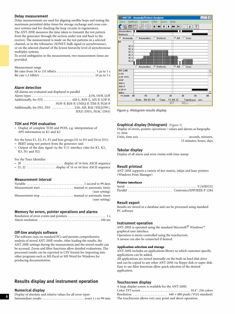
Graphical display (histogram) (Figure 5)Display of errors, pointer operations / values and alarms as bargraphsvs. timeUnits, time axis . . . . . . . . . . . . . . . . . . . . . . . . . . . . . . seconds, minutes,
15 minutes, hours, days
Tabular displayDisplay of all alarm and error events with time stamp
Result printoutANT-20SE supports a variety of dot-matrix, inkjet and laser printers(Windows Print Manager)
Printer interfacesSerial . . . . . . . . . . . . . . . . . . . . . . . . . . . . . . . . . . . . . . . . . . . V.24/RS232Parallel . . . . . . . . . . . . . . . . . . . . . . . . . . . Centronics/EPP/IEEE P 1284
Result exportResults are stored in a database and can be processed using standardPC software
Instrument operationANT-20SE is operated using the standard Microsoftâ WindowsTM
graphical user interface.Operation is menu-controlled using the touchscreen.A mouse can also be connected if desired.
Application selection and storageANT-20SE includes an applications library to which customer-specificapplications can be added.All applications are stored internally on the built-in hard disk driveand can be copied to any other ANT-20SE via floppy disk or super disk.Easy to use filter functions allow quick selection of the desiredapplication.
Touchscreen displayA large display screen is available for the ANT-20SE:Color TFT screen . . . . . . . . . . . . . . . . . . . . . . . . . . . . . . 10.4@, 256 colorsResolution . . . . . . . . . . . . . . . . . . . . . 6406480 pixels (VGA standard)The touchscreen allows very easy point and shoot operation.6
Figure 5: Histogram results display.

Built-in PCANT-20SE uses a Pentium PC as internal controller so that standardPC applications can also be run on the instrument.RAM capacity . . . . . . . . . . . . . . . . . . . . . . . . . . . . . . . . . . . . . . . . 64 MBLS-120 drive . . . . . . . . . . . . . . . . . . . . . . . . . . . . . . . . . . . . 3.5@, 120 MBHard disk drive . . . . . . . . . . . . . . . . . . . . . . . . . . . . . . . . . . . . . . . . 6 GBUSB interface, 10/100 Mbit/s Ethernet interface are included.
KeyboardFull keyboard for text input, extended PC applications and futurerequirements. The keyboard is protected by a fold back cover.An additional connector is provided for a standard PC keyboard.
External display connectorSimultaneous display with built-in screenInterface . . . . . . . . . . . . . . . . . . . . . . . . . . . . . . . . . . . . . . VGA standard
PCMCIA interfaceType . . . . . . . . . . . . . . . . . . . . . . . . . . . . PCMCIA 2.1 types I, II and IIIThe PCMCIA interface provides access to GPIB, LANs, etc.,via adapter cards.
Power outage functionIn the event of an AC line power failure during a measurement,ANT-20SE saves all data.As soon as the AC line voltage is reestablished, the measurement isresumed. Previous results are retained and the time of the power failureis recorded along with other events.
General specificationsPower supply (nominal range of use)AC line voltage,automatic switching . . . . . . . . . . . . . . . 100 to 127 V and 220 to 240 VAC line frequency . . . . . . . . . . . . . . . . . . . . . . . . . . . . . . . . . . . 50/60 HzPower consumption (all options fitted) . . . . . . . . . . . . . . . max. 500 VASafety class to IEC 1010-1 . . . . . . . . . . . . . . . . . . . . . . . . . . . . . . . Class I
Ambient temperatureNominal range of use . . . . . . . . . . . . 41� F to 104� F (+5 �C to +40 �C)Storage and transport range . . . . . . ± 4� F to 158� F (± 20 �C to +70 �C)
Dimensions (w6h6d) in mm . . . . . . . . . . . approx. 32063506280in inches . . . . . . . . . approx. 12.66 13.8611
Weight . . . . . . . . . . . . . . . . . . . . . . . . . . . . . . . . . . . approx. 15 kg/22 lb
Options
Extended SONET testing BN 3060/90.02
VT6 SPE mapping(6 Mbit/s unframed/Bulk in STS-1)
STS-1 SPE and STM-0 mappingErrors and alarms as for mainframe instrument
VT2 SPE and STM-0 mappingE1 in STS-1 and 2 Mbit/s in STM-0Modes . . . . . . . . . . . . . . . . asynchronous, byte synchronous (floating)Error insertion and alarm generation as for VT1.5 SPE mapping.
STS-3c mapping(140 Mbit/s in STS-3c and STM-1)
Byte capture TOH and POHTo analyze the TOH/POH functions, it is necessary to captureindividual bytes vs. time, allowing detection of errors or short-termchanges with frame level precision.The Capture function is started by a selectable trigger.Values for a selected byte are stored and can be accessed subsequentlyin a table of values.Particularly in capturing the APS sequences, the bytes (K1, K2) aredisplayed as an abbreviation of the standard commands.The function also allows recording of the N1 or N2 bytesfor evaluation of ªTandem Connectionº information.H4 sequences can also be analyzed very easily.The results can be printed or exported.Capture bytes for STS-1/-3/-3c, el. & opt . . . . . . . . all TOH/POH bytes
OC-N el. & opt . . . . . . . . . . . . . all TOH/POH bytes,channel 1 except A1, A2, B1
Storage depth for a byte . . . . . . . . . . . . . . . . . . . . . . . . . . . . . . . . . . 266K1, K2 . . . . . . . . . . . . . . . . . . . . . . . . . . . . . . . . . . 200
Trigger events . . . . . . . . . . . . . . . . . AIS-L, AIS-V, AIS-P, RDI-L, LOP-P,editable value in trigger byte
Capture resolution . . . . . . . . . . . . . . . . . . . . . . . . . . . . . frame precision
APS time measurementIn synchronous networks, a defined maximum switch-over time isnecessary for the traffic in case of a fault.To verify compliance with this requirement, the ANT-20SE measuresthe switch-over time with 1 ms resolution.The result can be printed.
Criteria for the time measurement . . . . . . . . . . . . AIS-L, AIS-V, AIS-P,bit error
Max. measurable switch-over time . . . . . . . . . . . . . . . . . . . . . . . . . . . 2 sResolution . . . . . . . . . . . . . . . . . . . . . . . . . . . . . . . . . . . . . . . . . . . . 1 msAllowable error rate for user signal . . . . . . . . . . . . . . . . . . . . 52610±4
Add SDH BN 3060/90.04
BERT (2, 8, 34, 140 Mbit/s)Signal structure and interfaces for generator and receiver:Framed and unframed test patternsAdditionally, for coaxial input/outputBit rate, line code . . . . . . . . . . . . . . . . . 2048, 8448, 34 368 kbit/s, HDB3Bit rate, line code . . . . . . . . . . . . . . . . . . . . . . . . . . . 139 264 kbit/s, CMIAdditionally, for balanced input/outputBit rate, line code . . . . . . . . . . . . . . . . . . . . . . . . . . . . 2048 kbit/s, HDB3
C4 mapping(140 Mbit/s in STM-1 and STS-3c)See ANT-20SE SDH datasheet for details.
C11 mapping(1.5 Mbit/s in STM-1, AU-3/AU-4)See ANT-20SE SDH datasheet for details.
C12 mapping(2 Mbit/s in STM-1, AU-3/AU-4)See ANT-20SE SDH datasheet for details.
C3 mapping(34 Mbit/s in STM-1, AU-3/AU-4)
C3 mapping(45 Mbit/s in STM-1, AU-3/AU-4)See ANT-20SE SDH datasheet for details.
C2 mapping(6 Mbit/s unframed/Bulk in STM-1)See ANT-20SE SDH datasheet for details. 7
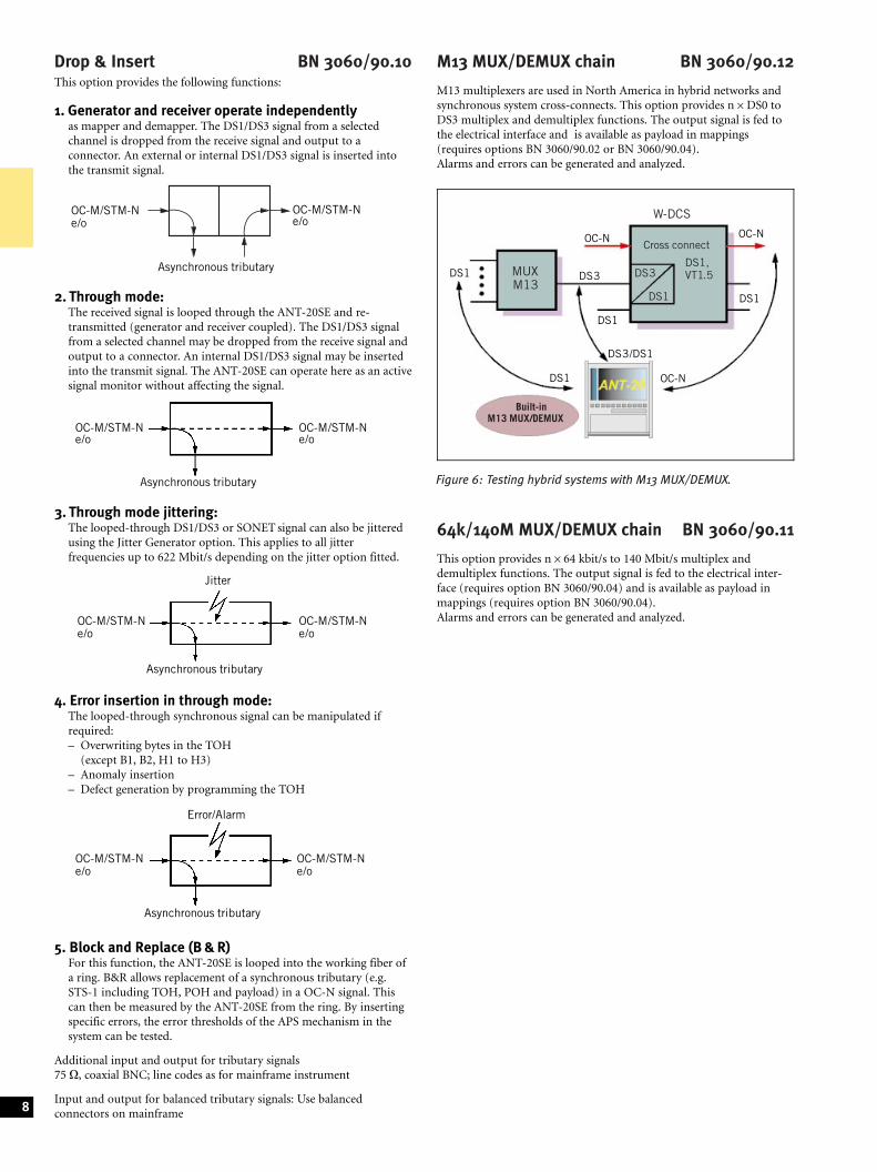
Figure 6: Testing hybrid systems with M13 MUX/DEMUX.
Drop & Insert BN 3060/90.10This option provides the following functions:
1. Generator and receiver operate independentlyas mapper and demapper. The DS1/DS3 signal from a selectedchannel is dropped from the receive signal and output to aconnector. An external or internal DS1/DS3 signal is inserted intothe transmit signal.
2. Through mode:The received signal is looped through the ANT-20SE and re-transmitted (generator and receiver coupled). The DS1/DS3 signalfrom a selected channel may be dropped from the receive signal andoutput to a connector. An internal DS1/DS3 signal may be insertedinto the transmit signal. The ANT-20SE can operate here as an activesignal monitor without affecting the signal.
3. Through mode jittering:The looped-through DS1/DS3 or SONET signal can also be jitteredusing the Jitter Generator option. This applies to all jitterfrequencies up to 622 Mbit/s depending on the jitter option fitted.
4. Error insertion in through mode:The looped-through synchronous signal can be manipulated ifrequired:± Overwriting bytes in the TOH
(except B1, B2, H1 to H3)± Anomaly insertion± Defect generation by programming the TOH
5. Block and Replace (B & R)For this function, the ANT-20SE is looped into the working fiber ofa ring. B&R allows replacement of a synchronous tributary (e.g.STS-1 including TOH, POH and payload) in a OC-N signal. Thiscan then be measured by the ANT-20SE from the ring. By insertingspecific errors, the error thresholds of the APS mechanism in thesystem can be tested.
Additional input and output for tributary signals75 O, coaxial BNC; line codes as for mainframe instrument
Input and output for balanced tributary signals: Use balancedconnectors on mainframe
M13 MUX/DEMUX chain BN 3060/90.12
M13 multiplexers are used in North America in hybrid networks andsynchronous system cross-connects. This option provides n6DS0 toDS3 multiplex and demultiplex functions. The output signal is fed tothe electrical interface and is available as payload in mappings(requires options BN 3060/90.02 or BN 3060/90.04).Alarms and errors can be generated and analyzed.
64k/140M MUX/DEMUX chain BN 3060/90.11
This option provides n664 kbit/s to 140 Mbit/s multiplex anddemultiplex functions. The output signal is fed to the electrical inter-face (requires option BN 3060/90.04) and is available as payload inmappings (requires option BN 3060/90.04).Alarms and errors can be generated and analyzed.
8
Asynchronous tributary
OC-M/STM-Ne/o
OC-M/STM-Ne/o
Asynchronous tributary
OC-M/STM-Ne/o
OC-M/STM-Ne/o
OC-M/STM-Ne/o
Asynchronous tributary
OC-M/STM-Ne/o
Jitter
Asynchronous tributary
OC-M/STM-Ne/o
Error/Alarm
OC-M/STM-Ne/o
Cross connect
DS1,VT1.5DS3
DS1
OC-N
W-DCS
OC-N
DS1
OC-N
Built-inM13 MUX/DEMUX
DS1
DS1
DS3MUXM13
DS3/DS1
DS1
Optical InterfacesAll of the optical interfaces are intended for single-mode fibers. Acternaoffers a complete line of optical test adapters. Select one test adaptereach for the generator and receiver from the ordering information inthis data sheet. All optical interface options include the requirednumber of test adapters.The STM-0 optical interface requires the option ªAdd SONETº.
Optical Modules up to 155 Mbit/s
Optical OC-1/3, STM-0/1, 1310 nm BN 3060/91.01
Optical OC-1/3, STM-0/1, 1310 & 1550 nm BN 3060/91.02Bit rate of TX and RX signal . . . . . . . . . . . . . . . . . . . . . . . 155 520 kbit/s
additionally, for STS-1/STM-0 mappings . . . . . . . . . . . 51 840 kbit/sLine code. . . . . . . . . . . . . . . . . . . . . . . . . . . . . . . . . . . . . scrambled NRZ
Generator unitThe generator meets the requirements of Telcordia GR-253,ANSI T1.105.06 (ITU-T Rec. G.957, Tables 2 and 3).Classes LR-1, LR-2, LR-3 (L1.1, L1.2 and L1.3) are covered.
There are two options for adapting to the required wavelength:Wavelength . . . . . . . . . . . . . . . . . . . . . . . . . . . . . . . . . . . . . . . . 1310 nm,
1310 & 1550 nm (switchable in the instrument)
Output level . . . . . . . . . . . . . . . . . . . . . . . . . . . . . . . . . 0 dBm +2/±3 dBwith 1310 & 1550 nm option . . . . . . . . . . . . . . . . . 0 dBm +2/±3.5 dB
Receiver unitThe receiver unit meets the specifications of Telcordia GR-253,ANSI T1.105.06 (ITU-T Rec. G.957) and fulfills classes IR-1, IR-2(S1.1 and S1.2).
Wavelength range . . . . . . . . . . . . . . . . . . . . . . . . . . . . . 1100 to 1580 nmInput sensitivity . . . . . . . . . . . . . . . . . . . . . . . . . . . . . . . . ±8 to ±28 dBm
(± 8 to ± 34 dBm typ.)Display of optical input levelResolution . . . . . . . . . . . . . . . . . . . . . . . . . . . . . . . . . . . . . . . . . . . . . 1 dB
155 Mbit/s electrical interfacefor connecting the ANT-20SE to STM-1/STS-3 monitor pointsLine code. . . . . . . . . . . . . . . . . . . . . . . . . . . . . . . . . . . . . scrambled NRZInput voltage (peak-peak) . . . . . . . . . . . . . . . . . . . . . . . . . . . . 0.2 to 1 VUnbalanced inputConnector/impedance . . . . . . . . . . . . . . . . . . . . . . . . . . . . . . SMA/50 O
Optical Modules up to 622 Mbit/s
Optical OC-1/3/12, STM-0/1/4, 1310 nm BN 3060/91.11
Optical OC-1/3/12,STM-0/1/4, 1310 & 1550 nm BN 3060/91.12Bit rate of TX andRX signal. . . . . . . . . . . . . . . . . . . . . . . . . . 155 520 kbit/s, 622 080 kbit/s
additionally, for STS-1/STM-0 mappings . . . . . . . . . . . 51 840 kbit/sLine code. . . . . . . . . . . . . . . . . . . . . . . . . . . . . . . . . . . . . scrambled NRZ
Generator unitThe generator meets the requirements of Telcordia GR 253,ANSI T1.105.06 (ITU-T Rec. G.957, Tables 2 and 3).Classes LR-1, LR-2, LR-3 (L1.1, L1.2, L1.3, L4.1, L4.2 and L4.3) arecovered.
There are two options for adapting to the required wavelength:Wavelength . . . . . . . . . . . . . . . . . . . . . . . . . . . . . . . . . . . . . . . . 1310 nm,
1310 & 1550 nm (switchable in the instrument)
Output level . . . . . . . . . . . . . . . . . . . . . . . . . . . . . . . . . 0 dBm +2/±3 dBwith 1310 & 1550 nm option . . . . . . . . . . . . . . . . . 0 dBm +2/±3.5 dB
Generation of OC-12 TX signalIn instruments with STS-1 mappings
The OC-12 TX signal consists of± one internally generated STS-1 tributary signal with the other
11 tributaries filled with UNEQ or± one internally generated STS-3c tributary signal with the other
three tributaries filled with UNEQ (with STS-3c mapping optionor ATM Basic Option BN 3060/90.50).
Generation of STM-4 TX signalIn instruments with STM-1 mappings
The STM-4 TX signal consists of± four identical STM-1 tributary signals (AU-4), or± one internally generated STM-1 tributary signal with the other
three tributaries filled with UNEQ.
Contents of the OC-12/STM-4 overhead bytesFor all bytes except B1, B2 and H1 to H3:± The content of each byte is statically programmable or a user
defined byte-sequence p in m in n (p frames in m frames and theentire sequence repeated n times) can be inserted.
For the E1, E2, F1 bytes and the DCC channelsD1 to D3 and D4 to D12:± Transmission of a test pattern with bit error insertion (see main-
frame for pattern selection)± Insertion of an external data signal (via the V.11 interface)
For the K1, K2, N1, N2 bytes:± Insertion of the data signal via the V.11 interface
For the J0 bytes:± Transmission of a 16-byte sequence, with CRC
Error insertionError types . . . . . . . . . . . . . . . . . . . . . . . . . . . . . . B1 and B2 parity erroradditionally, for OC-12 . . . . . . . . . . . . . . . . . . . . . . . . . . . . . . . . . REI-L
for STM-4 . . . . . . . . . . . . . . . . . . . . . . . . . . . . . . . . MS-REI
TriggeringSingle errors or error ratio . . . . . . . . . . . . . . . . . . . 2610±3 to 1610±10
for B1 parity errors . . . . . . . . . . . . . . . . . . . . . . . . . . 2610±4 to 1610±10
Burst error: m anomalies in n periodsFor FAS, B1, B2, B3, REI-L, REI-P . . . . . . . . . m = 1 to 4.86106 and
n = 2 to 8001 frames or 0.2 s to 600 s
Alarm generation, dynamicAlarm types for OC-12 . . . . . . . . . . . . . . . . . . . . . . . LOF, AIS-L, RDI-L
for STM-4 . . . . . . . . . . . . . . . . . . . LOF, MS-AIS, MS-RDIm alarms in n frames . . . . . . . . . . . . . . . . . . . m = 1 to n-1, nmax = 8000ort1 alarm active, t2 alarm passive . . . . . . . . . . . . . . . . . . . . t1 = 0 to 60 s,
t2 = 0 to 600 s
Alarm generation, static (on/off)Alarm types . . . . . . . . . . . . . . . . . . . . . . . . . . . . . . . . . . . . . . . LOS, LOFadditionally, for OC-12 . . . . . . . . . . . . . . . . . . . . . AIS-L, RDI-L, TIM-L
for STM-4 . . . . . . . . . . . . . . . . MS-AIS, MS-RDI, RS-TIMInsertion on/off 9
Receiver unitThe receiver unit meets the specifications of Telcordia GR 253,ANSI T1.105.06 (ITU-T Rec. G.957) and fulfills classes IR-1, IR-2,LR-1, LR-2, LR-3 (S1.1, S1.2, S4.1, S4.2, L4.1, L4.2 and L4.3).
Wavelength range . . . . . . . . . . . . . . . . . . . . . . . . . . . . . 1100 to 1580 nmInput sensitivity, OC-1/3/12 STM-1/-4, . . . . . . . . . . . . . ±8 to ±28 dBm
(± 8 to ± 34 dBm typ.)Display of optical input levelResolution . . . . . . . . . . . . . . . . . . . . . . . . . . . . . . . . . . . . . . . . . . . . . 1 dB
The ANT-20SE demultiplexes one selectable STS-3c/STS-1 orSTM-1 tributary from the OC-12/OC-3 or STM-4RX signal and feeds it to the internal processor for evaluation.
Measurement typesError measurementsError types . . . . . . . . . . . . . . . . . . . . . . . . . . . . . . . . . . . . B1 parity error,
B2 parity error of all STM-1/STS-1/STS-3c signals,MS-REI/REI-L
Alarm detectionAlarm types . . . . . . . . . . . . . . . . . . . . . . . . . . . . . . LOS, LOF, OOF, LTIadditionally, for OC-12 . . . . . . . . . . . . . . . . . . . . AIS-L, RDI-L, TIM-L
for STM-4 . . . . . . . . . . . . . . . . MS-AIS, MS-RDI, RS-TIM
Overhead evaluation± Display of the complete overhead of a selectable
STM-1/STS-1/STS-3c signal
For the E1, E2, F1 bytes and the DCC channelsD1 to D3 and D4 to D12:± BERT using a test pattern from the generator unit± Output of the data signal via the V.11 interface
For the K1, K2, N1, N2 bytes:± Data signal output via the V.11 interface
For the J0 byte:± Display of 15-byte sequences in ASCII.
155/622 Mbit/s electrical interfaceFor connecting the ANT-20SE to OC-3/STM-1 andOC-12/STM-4 monitor points
Line code. . . . . . . . . . . . . . . . . . . . . . . . . . . . . . . . . . . . . scrambled NRZInput voltage (peak-peak) . . . . . . . . . . . . . . . . . . . . . . . . . . . . 0.2 to 1 VCoaxial inputConnector / impedance . . . . . . . . . . . . . . . . . . . . . . . . . . . . . SMA / 50 O
Concatenated Mappings 622 Mbit/s
Option OC-12c/STM-4c BERT BN 3060/90.90Only in conjunction with BN 3060/91.11 or BN 3060/91.12
Contiguous concatenation signal structure to ANSI T1.105.02and G.707.Error measurement to O.150Test pattern . . . . . . . . . . . . . . . . . . . . . . . . . . . . . . PRBS-31, IPRBS-31,
PRBS-23, IPRBS-23,PRBS-20,
PRBS-15, IPRBS-15
Programmable wordLength . . . . . . . . . . . . . . . . . . . . . . . . . . . . . . . . . . . . . . . . . . . . . . 16 bits
Error insertionBit errors in test pattern, single error orerror ratio . . . . . . . . . . . . . . . . . . . . . . . . . . . . . . . . 1610±2 to 1610±9
Error measurement and alarm detectionBit errors and AIS in test pattern
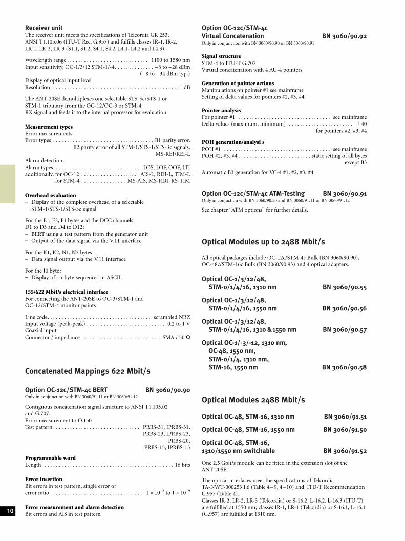
Option OC-12c/STM-4cVirtual Concatenation BN 3060/90.92Only in conjunction with BN 3060/90.90 or BN 3060/90.91
Signal structureSTM-4 to ITU-T G.707Virtual concatenation with 4 AU-4 pointers
Generation of pointer actionsManipulations on pointer #1 see mainframeSetting of delta values for pointers #2, #3, #4
Pointer analysisFor pointer #1 . . . . . . . . . . . . . . . . . . . . . . . . . . . . . . . . . see mainframeDelta values (maximum, minimum) . . . . . . . . . . . . . . . . . . . . . . . +40
for pointers #2, #3, #4
POH generation/analysi sPOH #1 . . . . . . . . . . . . . . . . . . . . . . . . . . . . . . . . . . . . . . see mainframePOH #2, #3, #4 . . . . . . . . . . . . . . . . . . . . . . . . . . static setting of all bytes
except B3
Automatic B3 generation for VC-4 #1, #2, #3, #4
Option OC-12c/STM-4c ATM-Testing BN 3060/90.91Only in conjuction with BN 3060/90.50 and BN 3060/91.11 or BN 3060/91.12
See chapter ªATM optionsº for further details.
Optical Modules up to 2488 Mbit/s
All optical packages include OC-12c/STM-4c Bulk (BN 3060/90.90),OC-48c/STM-16c Bulk (BN 3060/90.93) and 4 optical adapters.
Optical OC-1/3/12/48,STM-0/1/4/16, 1310 nm BN 3060/90.55
Optical OC-1/3/12/48,STM-0/1/4/16, 1550 nm BN 3060/90.56
Optical OC-1/3/12/48,STM-0/1/4/16, 1310 &1550 nm BN 3060/90.57
Optical OC-1/-3/-12, 1310 nm,OC-48, 1550 nm,STM-0/1/4, 1310 nm,STM-16, 1550 nm BN 3060/90.58
Optical Modules 2488 Mbit/s
Optical OC-48, STM-16, 1310 nm BN 3060/91.51
Optical OC-48, STM-16, 1550 nm BN 3060/91.50
Optical OC-48, STM-16,1310/1550 nm switchable BN 3060/91.52
One 2.5 Gbit/s module can be fitted in the extension slot of theANT-20SE.
The optical interfaces meet the specifications of TelcordiaTA-NWT-000253 I.6 (Table 4 ± 9, 4 ±10) and ITU-T RecommendationG.957 (Table 4).Classes IR-2, LR-2, LR-3 (Telcordia) or S-16.2, L-16.2, L-16.3 (ITU-T)are fulfilled at 1550 nm; classes IR-1, LR-1 (Telcordia) or S-16.1, L-16.1(G.957) are fulfilled at 1310 nm.10
Generator
Optical interfacesWavelengths . . . . . . . . . . . . . . . . . . . . . . . . . . . . . . . . 1310 nm, 1550 nm
or 1310/1550 nm switchableOutput level at 1310 nm and 1550 nm . . . . . . . . . . . . 0 dBm +0/± 2 dBLine code . . . . . . . . . . . . . . . . . . . . . . . . . . . . . . . . . . . . scrambled NRZ
Electrical interfacesLine code. . . . . . . . . . . . . . . . . . . . . . . . . . . . . . . . . . . . . scrambled NRZOutput voltage (peak-peak). . . . . . . . . . . . . . . . . . . . . . . . . . . . . -40.6 VConnector/impedance . . . . . . . . . . . . . . . . . . . . . . . . . . . . . . SMA/50 O
Clock generatorInternal, accuracy . . . . . . . . . . . . . . . . . . . . . . . . . . . . . . . . . . . +2 ppmOffset. . . . . . . . . . . . . . . . . . . . . . . . . . . . . . . . . . . . . . . . . . . . . +50 ppmSynchronization from external signal as for mainframe
Generation of OC-48 TX signalIn instruments with STS-1/STS-3c mappings
The OC-48 signal consists of one or more internally generatedtributaries plus several tributaries filled with UNEQ (or non-specificUNEQ)± 48 identical STS-1± One STS-1 tributary and 476UNEQ/non specific± 16 identical STS-3c (Option BN 3060/90.02 required)± One STS-3c tributary (Option BN 3060/90.02 required)
and 156UNEQ/non specific± Four identical STS-12c (Option BN 3060/90.90 required)± One STS-12c tributary (Option BN 3060/90.90 required)
and 36UNEQ/non specific
Generation of STM-16 TX signalIn instruments with STM-1 mappings
The STM-16 signal consists of one or more internally generatedtributaries plus several tributaries filled withUNEQ (or non-specific UNEQ)± 16 identical STM-1± One STM-1 tributary and 156UNEQ/non specific± Four identical STM-4c (Option BN 3060/90.90 required)± One STM-4c tributary (Option BN 3060/90.90 required)
and 36UNEQ/non specific
Contents of OC-48/STM-16 overhead bytesFor all bytes except B1, B2 and H1 through to H3:± The contents of the bytes in all SOH/TOH are statically
programmable
For the bytes E1, E2, F1 and the DCC channels D1 to D3 andD4 to D12:± Transmission of a test pattern and bit error insertion
(see mainframe for pattern selection)± Insertion of an externally-generated data signal
(via V.11 interface)
For the K1, K2, N1, N2 bytes:± Insertion of an external data signal via the V.11 interface
For the J0 byte:± Transmission of a 16-bit sequence with CRC
Error insertionError types . . . . . . . . . . . . . . . . . . . . . . . . . . . . . . . . B1, B2 parity errorsSingle error or error rate B1 . . . . . . . . . . . . . . . . . . 2610±5 to 1610±10
B2 . . . . . . . . . . . . . . . . . . 2610±3 to 1610±10
additionally, for OC-48 . . . . . . . . . . . . . . . . . . . . . . . . . . . . . . . . . .REI-Lfor STM-16 . . . . . . . . . . . . . . . . . . . . . . . . . . . . . . MS-REI
Single error or error rate . . . . . . . . . . . . . . . . . . . . . 2610±3 to 1610±10
Alarm generation, dynamicAlarm types for OC-48 . . . . . . . . . . . . . . . . . . . . . . . LOF, AIS-L, RDI-L
for STM-16 . . . . . . . . . . . . . . . . . . LOF, MS-AIS, MS-RDI
m alarms in n frames . . . . . . . . . . . . . . . . . . . m = 1 to n-1, nmax = 8000or
t1 alarm active, t2 alarm passive . . . . . . . . . . . . . . . . . . . . t1 = 0 to 60 s,t2 = 0 to 600 s
Alarm generation, static (on/off)Alarm types . . . . . . . . . . . . . . . . . . . . . . . . . . . . . . . . . . . . . . . LOS, LOFadditionally, for OC-48 . . . . . . . . . . . . . . . . . . . . . . . . . . . .AIS-L, RDI-L
for STM-16 . . . . . . . . . . . . . . . . . . . . . . . MS-AIS, MS-RDI
Receiver
Optical interfacesWavelength . . . . . . . . . . . . . . . . . . . . . . . . . . . . . . . . . 1260 to 1580 nmLine code. . . . . . . . . . . . . . . . . . . . . . . . . . . . . . . . . . . . . scrambled NRZSensitivity . . . . . . . . . . . . . . . . . . . . . . . . . . . . . . . . . . . . ± 28 to ± 8 dBmInput overload . . . . . . . . . . . . . . . . . . . . . . . . . . . . . . . . . . . . . 4± 8 dBm
Display of optical input levelRange . . . . . . . . . . . . . . . . . . . . . . . . . . . . . . . . . . . . . . . ± 30 to ± 8 dBmResolution . . . . . . . . . . . . . . . . . . . . . . . . . . . . . . . . . . . . . . . . . . . . . 1 dB
Electrical interfacesLine code . . . . . . . . . . . . . . . . . . . . . . . . . . . . . . . . . . . . scrambled NRZInput voltage (peak-peak) . . . . . . . . . . . . . . . . . . . . . . . . . . . . 0.3 to 1 VConnector/impedance . . . . . . . . . . . . . . . . . . . . . . . . . . . . . . SMA/50 O
A selectable STM-1, STS-1 or STS-3c channel is fed to the internalevaluation circuits by demultiplexing from the input signal.
Error measurementError types . . . . . . . . . . . . . . . . . . . . . . . . . . . . B1 parity error, MS-REI,
B2 parity sum error overall STM-1/STS-1/STS-3c channels
Evaluation (bit/block errors) . . . . . . . . . . . . . . . . . . . . error rate, countError event resolution . . . . . . . . . . . . . . . . . . . . . . . . . . . . . . . . . . . . . 1 s
Alarm detectionAlarm typs . . . . . . . . . . . . . . . . . . . . . . . . . . . . . . . . . . . LOS, LOF, OOFadditionally, for OC-48 . . . . . . . . . . . . . . . . . . . . . AIS-L, RDI-L, TIM-L
for STM-16 . . . . . . . . . . . . . . . MS-AIS, MS-RDI, RS-TIMAlarm event resolution . . . . . . . . . . . . . . . . . . . . . . . . . . . . . . . . 100 ms
TOH/SOH evaluationDisplay of complete overhead
For the bytes E1, E2, F1 and the DCC channels D1 to D3 and D4to D12:± BERT using test pattern from generator unit± Output of the data signal via the V.11 interface
For the K1, K2, N1, N2 bytes:± Data signal output via the V.11 interface
For the J0 byte:± Display of 15-byte sequences in ASCII format
Concatenated Mapping 2488 Mbit/s
Option OC-48c/STM-16c BERT BN 3060/90.93Only in conjunction with BN 3060/91.50 to /91.53
Contiguous concatenation signal structure to ANSI T1.105.02 andG.707.
Error measurement to O.150Test pattern . . . . . . . . . . . . . . . . . . . . . . . . . . . . . . . PRBS-31, IPRBS-31
PRBS-23, IPRBS-23Programmable wordLength . . . . . . . . . . . . . . . . . . . . . . . . . . . . . . . . . . . . . . . . . . . . . . . 16 bits
Error insertionBit errors in test pattern, single error orerror ratio . . . . . . . . . . . . . . . . . . . . . . . . . . . . . . . . 1610±3 to 1610±9 11
Alarm generation:AU-AIS, AIS-C1...AIS-C16,AU-LOP, LOP-C1...LOP-C16
Error measurement and alarm detection:AU-AIS, AU-LOPBit errors
Automatic Protection SwitchingSensor: MS-AIS, AU-AIS
Solutions for 10 Gbit/s
With the new ANT-10Gig we provide a 10 Gbit/s solution which coversOC-192 as well as STM-64. The ANT-10Gig allows testing at thehighest line bit rate and in all mappings below and offers optionally alltesting down to n664 kbit/s.For detailed information please refer to data sheet ªANT-10Gigº.The ANT-20SE is prepared for upgrades towards STM-64/OC-192.
Further options
Optical Power Splitter (90%/10 %) BN 3060/91.05The Optical Power Splitter is built into the ANT-20SE.Three optical test adapters are required to operate it; please indicateyour choice.
The Optical Power Splitter provides an optical monitor point. Theinput signal is passed through to the output transparently.
Light energy forwarded . . . . . . . . . . . . . . . . . . approx. 90 % (± 0.45 dB)Light energy coupled out . . . . . . . . . . . . . . . . . approx. 10 % (±10 dB)
The Optical Power Splitter operates in the following ranges:Wavelengths . . . . . . . . . . . . . . . 1260 to 1360 nm and 1500 to 1600 nm
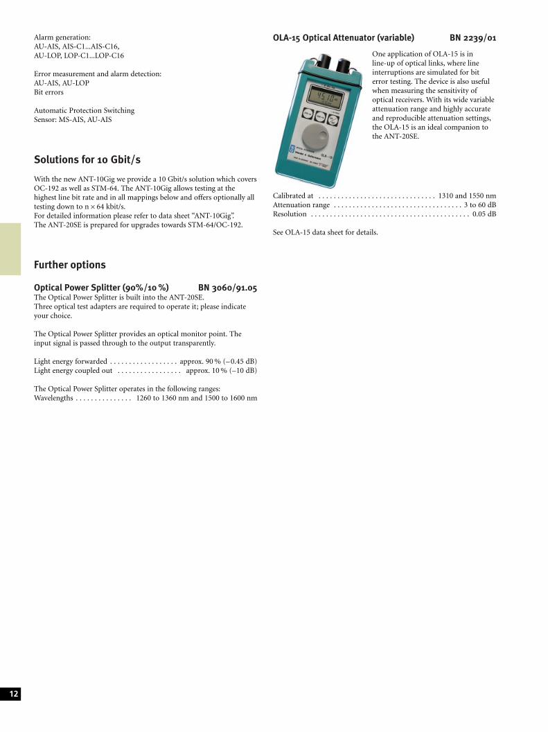
OLA-15 Optical Attenuator (variable) BN 2239/01
One application of OLA-15 is inline-up of optical links, where lineinterruptions are simulated for biterror testing. The device is also usefulwhen measuring the sensitivity ofoptical receivers. With its wide variableattenuation range and highly accurateand reproducible attenuation settings,the OLA-15 is an ideal companion tothe ANT-20SE.
Calibrated at . . . . . . . . . . . . . . . . . . . . . . . . . . . . . . . 1310 and 1550 nmAttenuation range . . . . . . . . . . . . . . . . . . . . . . . . . . . . . . . . . . 3 to 60 dBResolution . . . . . . . . . . . . . . . . . . . . . . . . . . . . . . . . . . . . . . . . . . 0.05 dB
See OLA-15 data sheet for details.
12
Jitter and Wander OptionsStandards
Jitter generation and jitter/wander analysis are in accordance with:± Telcordia GR-253, GR-499, GR-1244± ANSI T1.101, T1.102, T1.105.03,T1.403, T1.404, T1.105.09± ITU-T G.783, G.823, G.824, G.825, O.171, O.172± ETSI ETS 300 462-1 to -6, ETS 300 417-1-1, EN 302 084
O.172 Jitter/Wanderup to 155 Mbit/s BN 3060/91.30
Jitter generatorFully complies with or exceeds the requirements of ITU-T O.172.
Bit ratesGenerates jitter at all bit rates included in the mainframe configurationup to 155 520 kbit/s.
TX signals . . . . . . . . . . . . . . . . . . all test patterns and frame structuresincluded in the mainframe configuration
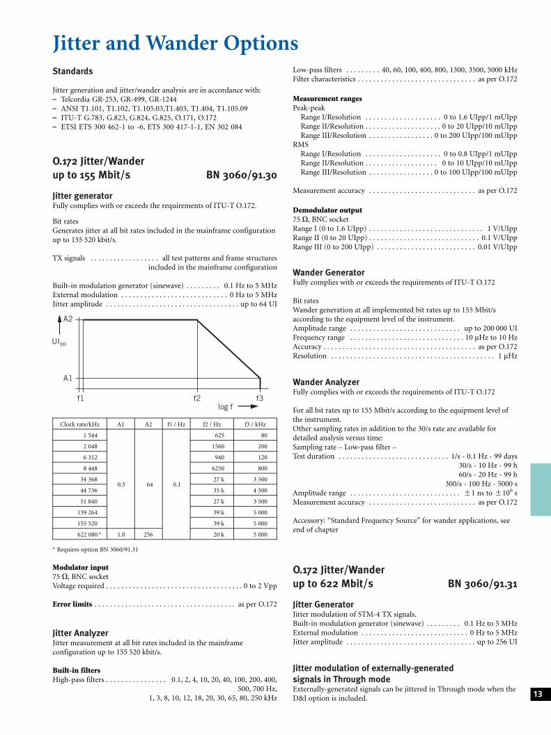
Built-in modulation generator (sinewave) . . . . . . . . . 0.1 Hz to 5 MHzExternal modulation . . . . . . . . . . . . . . . . . . . . . . . . . . . . 0 Hz to 5 MHzJitter amplitude . . . . . . . . . . . . . . . . . . . . . . . . . . . . . . . . . . . up to 64 UI
Clock rate/kHz A1 A2 f1 / Hz f2 / Hz f3 / kHz
1 544
0.5 64 0.1
625 80
2 048 1560 200
6 312 940 120
8 448 6250 800
34 368 27 k 3 500
44 736 35 k 4 500
51 840 27 k 3 500
139 264 39 k 5 000
155 520 39 k 5 000
622 080 * 1.0 256 20 k 5 000
* Requires option BN 3060/91.31
Modulator input75 O, BNC socketVoltage required . . . . . . . . . . . . . . . . . . . . . . . . . . . . . . . . . . . . 0 to 2 Vpp
Error limits . . . . . . . . . . . . . . . . . . . . . . . . . . . . . . . . . . . . . as per O.172
Jitter AnalyzerJitter measurement at all bit rates included in the mainframeconfiguration up to 155 520 kbit/s.
Built-in filtersHigh-pass filters . . . . . . . . . . . . . . . . 0.1, 2, 4, 10, 20, 40, 100, 200, 400,
500, 700 Hz,1, 3, 8, 10, 12, 18, 20, 30, 65, 80, 250 kHz
Low-pass filters . . . . . . . . . 40, 60, 100, 400, 800, 1300, 3500, 5000 kHzFilter characteristics . . . . . . . . . . . . . . . . . . . . . . . . . . . . . . . as per O.172
Measurement rangesPeak-peak
Range I/Resolution . . . . . . . . . . . . . . . . . . . . 0 to 1.6 UIpp/1 mUIppRange II/Resolution . . . . . . . . . . . . . . . . . . . . 0 to 20 UIpp/10 mUIppRange III/Resolution . . . . . . . . . . . . . . . . . 0 to 200 UIpp/100 mUIpp
RMSRange I/Resolution . . . . . . . . . . . . . . . . . . . . 0 to 0.8 UIpp/1 mUIppRange II/Resolution . . . . . . . . . . . . . . . . . . . 0 to 10 UIpp/10 mUIppRange III/Resolution . . . . . . . . . . . . . . . . . 0 to 100 UIpp/100 mUIpp
Measurement accuracy . . . . . . . . . . . . . . . . . . . . . . . . . . . . as per O.172
Demodulator output75 O, BNC socketRange I (0 to 1.6 UIpp) . . . . . . . . . . . . . . . . . . . . . . . . . . . . . . 1 V/UIppRange II (0 to 20 UIpp) . . . . . . . . . . . . . . . . . . . . . . . . . . . . . 0.1 V/UIppRange III (0 to 200 UIpp) . . . . . . . . . . . . . . . . . . . . . . . . . . 0.01 V/UIpp
Wander GeneratorFully complies with or exceeds the requirements of ITU-T O.172
Bit ratesWander generation at all implemented bit rates up to 155 Mbit/saccording to the equipment level of the instrument.Amplitude range . . . . . . . . . . . . . . . . . . . . . . . . . . . . . up to 200 000 UIFrequency range . . . . . . . . . . . . . . . . . . . . . . . . . . . . . . 10 mHz to 10 HzAccuracy . . . . . . . . . . . . . . . . . . . . . . . . . . . . . . . . . . . . . . . . as per O.172Resolution . . . . . . . . . . . . . . . . . . . . . . . . . . . . . . . . . . . . . . . . . . . 1 mHz
Wander AnalyzerFully complies with or exceeds the requirements of ITU-T O.172
For all bit rates up to 155 Mbit/s according to the equipment level ofthe instrument.Other sampling rates in addition to the 30/s rate are available fordetailed analysis versus time:Sampling rate ± Low-pass filter ±Test duration . . . . . . . . . . . . . . . . . . . . . . . . . . . . . 1/s - 0.1 Hz - 99 days
30/s - 10 Hz - 99 h60/s - 20 Hz - 99 h
300/s - 100 Hz - 5000 sAmplitude range . . . . . . . . . . . . . . . . . . . . . . . . . . . . . +1 ns to +106 sMeasurement accuracy . . . . . . . . . . . . . . . . . . . . . . . . . . . . as per O.172
Accessory: ªStandard Frequency Sourceº for wander applications, seeend of chapter
O.172 Jitter/Wanderup to 622 Mbit/s BN 3060/91.31
Jitter GeneratorJitter modulation of STM-4 TX signals.Built-in modulation generator (sinewave) . . . . . . . . . 0.1 Hz to 5 MHzExternal modulation . . . . . . . . . . . . . . . . . . . . . . . . . . . . 0 Hz to 5 MHzJitter amplitude . . . . . . . . . . . . . . . . . . . . . . . . . . . . . . . . . . up to 256 UI
Jitter modulation of externally-generatedsignals in Through modeExternally-generated signals can be jittered in Through mode when theD&I option is included. 13
A2
UIpp
A1
f1 f2log f
f3
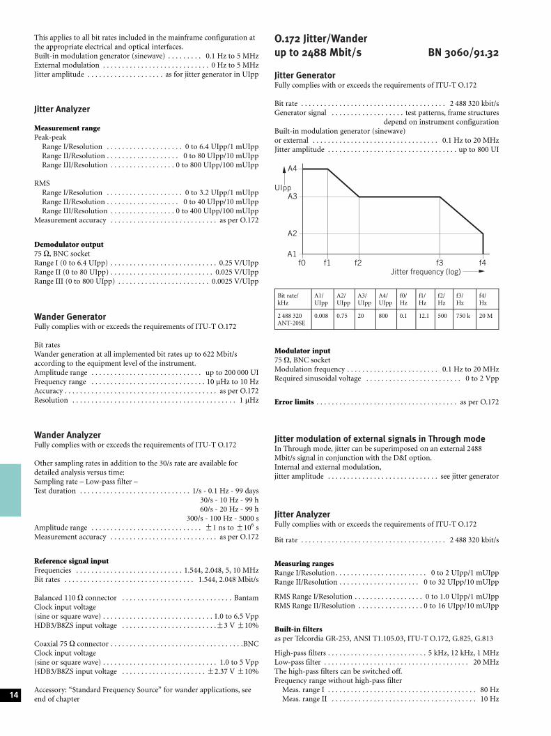
This applies to all bit rates included in the mainframe configuration atthe appropriate electrical and optical interfaces.Built-in modulation generator (sinewave) . . . . . . . . . 0.1 Hz to 5 MHzExternal modulation . . . . . . . . . . . . . . . . . . . . . . . . . . . . 0 Hz to 5 MHzJitter amplitude . . . . . . . . . . . . . . . . . . . . as for jitter generator in UIpp
Jitter Analyzer
Measurement rangePeak-peak
Range I/Resolution . . . . . . . . . . . . . . . . . . . . 0 to 6.4 UIpp/1 mUIppRange II/Resolution . . . . . . . . . . . . . . . . . . . 0 to 80 UIpp/10 mUIppRange III/Resolution . . . . . . . . . . . . . . . . . 0 to 800 UIpp/100 mUIpp
RMSRange I/Resolution . . . . . . . . . . . . . . . . . . . . 0 to 3.2 UIpp/1 mUIppRange II/Resolution . . . . . . . . . . . . . . . . . . . 0 to 40 UIpp/10 mUIppRange III/Resolution . . . . . . . . . . . . . . . . . 0 to 400 UIpp/100 mUIpp
Measurement accuracy . . . . . . . . . . . . . . . . . . . . . . . . . . . . as per O.172
Demodulator output75 O, BNC socketRange I (0 to 6.4 UIpp) . . . . . . . . . . . . . . . . . . . . . . . . . . . . 0.25 V/UIppRange II (0 to 80 UIpp) . . . . . . . . . . . . . . . . . . . . . . . . . . . 0.025 V/UIppRange III (0 to 800 UIpp) . . . . . . . . . . . . . . . . . . . . . . . . 0.0025 V/UIpp
Wander GeneratorFully complies with or exceeds the requirements of ITU-T O.172
Bit ratesWander generation at all implemented bit rates up to 622 Mbit/saccording to the equipment level of the instrument.Amplitude range . . . . . . . . . . . . . . . . . . . . . . . . . . . . . up to 200 000 UIFrequency range . . . . . . . . . . . . . . . . . . . . . . . . . . . . . . 10 mHz to 10 HzAccuracy . . . . . . . . . . . . . . . . . . . . . . . . . . . . . . . . . . . . . . . . as per O.172Resolution . . . . . . . . . . . . . . . . . . . . . . . . . . . . . . . . . . . . . . . . . . . 1 mHz
Wander AnalyzerFully complies with or exceeds the requirements of ITU-T O.172
Other sampling rates in addition to the 30/s rate are available fordetailed analysis versus time:Sampling rate ± Low-pass filter ±Test duration . . . . . . . . . . . . . . . . . . . . . . . . . . . . . 1/s - 0.1 Hz - 99 days
30/s - 10 Hz - 99 h60/s - 20 Hz - 99 h
300/s - 100 Hz - 5000 sAmplitude range . . . . . . . . . . . . . . . . . . . . . . . . . . . . . +1 ns to +106 sMeasurement accuracy . . . . . . . . . . . . . . . . . . . . . . . . . . . . as per O.172
Reference signal inputFrequencies . . . . . . . . . . . . . . . . . . . . . . . . . . . . 1.544, 2.048, 5, 10 MHzBit rates . . . . . . . . . . . . . . . . . . . . . . . . . . . . . . . . . . 1.544, 2.048 Mbit/s
Balanced 110 O connector . . . . . . . . . . . . . . . . . . . . . . . . . . . . . BantamClock input voltage(sine or square wave) . . . . . . . . . . . . . . . . . . . . . . . . . . . . . 1.0 to 6.5 VppHDB3/B8ZS input voltage . . . . . . . . . . . . . . . . . . . . . . . . .+3 V +10%
Coaxial 75 O connector . . . . . . . . . . . . . . . . . . . . . . . . . . . . . . . . . . .BNCClock input voltage(sine or square wave) . . . . . . . . . . . . . . . . . . . . . . . . . . . . . . 1.0 to 5 VppHDB3/B8ZS input voltage . . . . . . . . . . . . . . . . . . . . . . +2.37 V +10%
Accessory: ªStandard Frequency Sourceº for wander applications, seeend of chapter
O.172 Jitter/Wanderup to 2488 Mbit/s BN 3060/91.32
Jitter GeneratorFully complies with or exceeds the requirements of ITU-T O.172
Bit rate . . . . . . . . . . . . . . . . . . . . . . . . . . . . . . . . . . . . . . 2 488 320 kbit/sGenerator signal . . . . . . . . . . . . . . . . . . . test patterns, frame structures
depend on instrument configurationBuilt-in modulation generator (sinewave)or external . . . . . . . . . . . . . . . . . . . . . . . . . . . . . . . . . 0.1 Hz to 20 MHzJitter amplitude . . . . . . . . . . . . . . . . . . . . . . . . . . . . . . . . . . up to 800 UI
Bit rate/kHz
A1/UIpp
A2/UIpp
A3/UIpp
A4/UIpp
f0/Hz
f1/Hz
f2/Hz
f3/Hz
f4/Hz
2 488 320ANT-20SE
0.008 0.75 20 800 0.1 12.1 500 750 k 20 M
Modulator input75 O, BNC socketModulation frequency . . . . . . . . . . . . . . . . . . . . . . . . 0.1 Hz to 20 MHzRequired sinusoidal voltage . . . . . . . . . . . . . . . . . . . . . . . . . 0 to 2 Vpp
Error limits . . . . . . . . . . . . . . . . . . . . . . . . . . . . . . . . . . . . . as per O.172
Jitter modulation of external signals in Through modeIn Through mode, jitter can be superimposed on an external 2488Mbit/s signal in conjunction with the D&I option.Internal and external modulation,jitter amplitude . . . . . . . . . . . . . . . . . . . . . . . . . . . . . see jitter generator
Jitter AnalyzerFully complies with or exceeds the requirements of ITU-T O.172
Bit rate . . . . . . . . . . . . . . . . . . . . . . . . . . . . . . . . . . . . . . 2 488 320 kbit/s
Measuring rangesRange I/Resolution . . . . . . . . . . . . . . . . . . . . . . . . 0 to 2 UIpp/1 mUIppRange II/Resolution . . . . . . . . . . . . . . . . . . . . . 0 to 32 UIpp/10 mUIpp
RMS Range I/Resolution . . . . . . . . . . . . . . . . . . 0 to 1.0 UIpp/1 mUIppRMS Range II/Resolution . . . . . . . . . . . . . . . . . 0 to 16 UIpp/10 mUIpp
Built-in filtersas per Telcordia GR-253, ANSI T1.105.03, ITU-T O.172, G.825, G.813
High-pass filters . . . . . . . . . . . . . . . . . . . . . . . . . . 5 kHz, 12 kHz, 1 MHzLow-pass filter . . . . . . . . . . . . . . . . . . . . . . . . . . . . . . . . . . . . . . 20 MHzThe high-pass filters can be switched off.Frequency range without high-pass filter
Meas. range I . . . . . . . . . . . . . . . . . . . . . . . . . . . . . . . . . . . . . . . 80 HzMeas. range II . . . . . . . . . . . . . . . . . . . . . . . . . . . . . . . . . . . . . . 10 Hz14
A4
A3
A2
A1
UIpp
f0 f1 f2 f3 f4Jitter frequency (log)
Measuring modes . . . . . . . . . . . . . . . . . . . . . . . . . . . . see Jitter Analysis
Demodulator outpur75 O, BNC socketOutput voltageMeas. range I (0 to 2 UIpp) . . . . . . . . . . . . . . . . . . . . . . . . . . 1 V/UIppMeas. range II (0 to 32 UIpp) . . . . . . . . . . . . . . . . . . . . . 62.5 mV/UIpp
Automatic tests . . . . . . . . . . . . . . . . . like jitter meter up to 622 Mbit/sTolerance masks atMTJ/F-MTJ . . . . . . . . . . . . . . . . . . ANSI T1.105.03, Telcordia GR-253,
ITU-T G.825JTF . . . . . . . . . . . . . . . . . . . Telcordia GR-253, ANSI T1.105.03 type A,
ITU-T G.958
Wander GeneratorFully complies with or exceeds the requirementsof ITU-T O.172Amplitude range. . . . . . . . . . . . . . . . . . . . . . . . . . . . . . up to 200 000 UIFrequency range . . . . . . . . . . . . . . . . . . . . . . . . . . . . . . 10 mHz to 10 HzAccuracy . . . . . . . . . . . . . . . . . . . . . . . . . . . . . . . . . . . . . . . . as per O.172Resolution . . . . . . . . . . . . . . . . . . . . . . . . . . . . . . . . . . . . . . . . . . . 1 mHz
Wander AnalyzerOther sampling rates in addition to the 30/s rate areavailable for detailed analysis versus time:Sampling rate ± Low-pass filter ±Test duration . . . . . . . . . . . . . . . . . . . . . . . . . . . . . 1/s - 0.1 Hz - 99 days
30/s - 10 Hz - 99 h60/s - 20 Hz - 99 h
300/s - 100 Hz - 5000 sAmplitude range . . . . . . . . . . . . . . . . . . . . . . . . . . . . . .+1 ns to +106 sMeasurement accuracy . . . . . . . . . . . . . . . . . . . . . . . . . . . . as per O.172
Evaluation capabilitiessee Wander Analysis
Reference signal input75 O, BNC socketFrequencies . . . . . . . . . . . . . . . . . . . . . . . . . . . . 1.544, 2.048, 5, 10 MHzInput voltage . . . . . . . . . . . . . . . . . . . . . . . . . . . . . . . . . . . . 0.5 to 5 VppInput signal monitoring(Loss of Timing Input). . . . . . . . . . . . . . . . . . . . . . . . . . . . . . . . . . . . . LTI
Accessory: ªStandard Frequency Sourceº for wander applications, seeend of chapter
Jitter Analysis
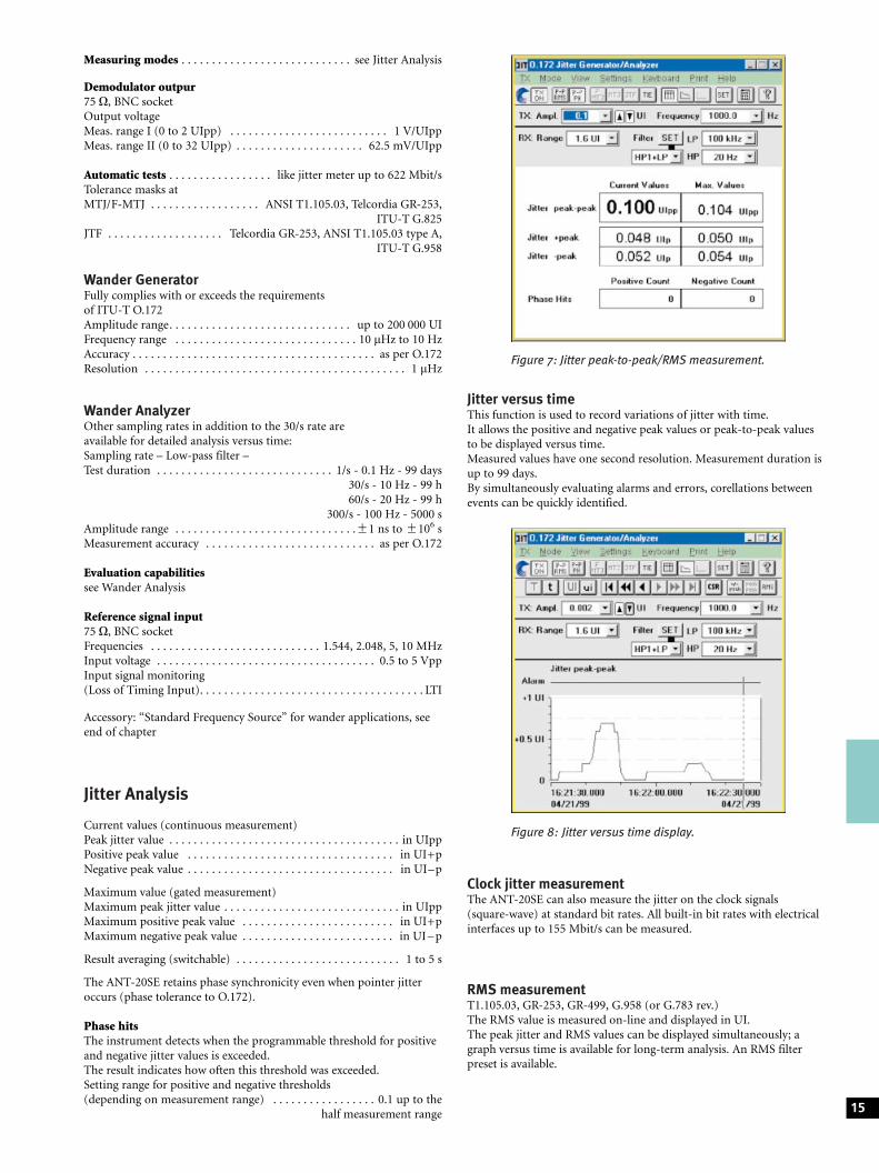
Current values (continuous measurement)Peak jitter value . . . . . . . . . . . . . . . . . . . . . . . . . . . . . . . . . . . . . . in UIppPositive peak value . . . . . . . . . . . . . . . . . . . . . . . . . . . . . . . . . . in UI+pNegative peak value . . . . . . . . . . . . . . . . . . . . . . . . . . . . . . . . . . in UI±p
Maximum value (gated measurement)Maximum peak jitter value . . . . . . . . . . . . . . . . . . . . . . . . . . . . . in UIppMaximum positive peak value . . . . . . . . . . . . . . . . . . . . . . . . . in UI+pMaximum negative peak value . . . . . . . . . . . . . . . . . . . . . . . . . in UI ± p
Result averaging (switchable) . . . . . . . . . . . . . . . . . . . . . . . . . . . 1 to 5 s
The ANT-20SE retains phase synchronicity even when pointer jitteroccurs (phase tolerance to O.172).
Phase hitsThe instrument detects when the programmable threshold for positiveand negative jitter values is exceeded.The result indicates how often this threshold was exceeded.Setting range for positive and negative thresholds(depending on measurement range) . . . . . . . . . . . . . . . . . 0.1 up to the
half measurement range
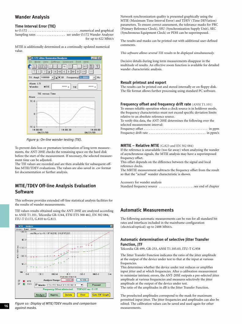
Jitter versus timeThis function is used to record variations of jitter with time.It allows the positive and negative peak values or peak-to-peak valuesto be displayed versus time.Measured values have one second resolution. Measurement duration isup to 99 days.By simultaneously evaluating alarms and errors, corellations betweenevents can be quickly identified.
Clock jitter measurementThe ANT-20SE can also measure the jitter on the clock signals(square-wave) at standard bit rates. All built-in bit rates with electricalinterfaces up to 155 Mbit/s can be measured.
RMS measurementT1.105.03, GR-253, GR-499, G.958 (or G.783 rev.)The RMS value is measured on-line and displayed in UI.The peak jitter and RMS values can be displayed simultaneously; agraph versus time is available for long-term analysis. An RMS filterpreset is available.
15
Figure 7: Jitter peak-to-peak/RMS measurement.
Figure 8: Jitter versus time display.
Wander Analysis
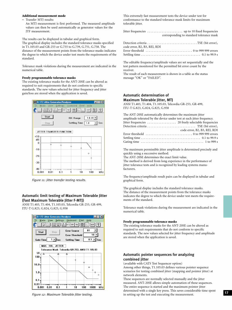
Time Interval Error (TIE)to O.172 . . . . . . . . . . . . . . . . . . . . . . . . . . . . . . .numerical and graphicalSampling rates . . . . . . . . . . . . . . . . . see under O.172 Wander Analyzer
for up to 622 Mbit/s
MTIE is additionally determined as a continually updated numericalvalue.
To prevent data loss or premature termination of long term measure-ments, the ANT-20SE checks the remaining space on the hard diskbefore the start of the measurement. If necessary, the selected measure-ment time can be adjusted.The TIE values are recorded and are then available for subsequent off-line MTIE/TDEV evaluations. The values are also saved in .csv formatfor documentation or further analysis.
MTIE/TDEV Off-line Analysis EvaluationSoftware
This software provides extended off-line statistical analysis facilities forthe results of wander measurements.
TIE values results obtained using the ANT-20SE are analyzed accordingto ANSI T1.101, Telcordia GR-1244, ETSI ETS 300 462, EN 302 084,ITU-T O.172, G.810 to G.813.
Network synchronization quality is presented graphically using theMTIE (Maximum Time Interval Error) and TDEV (Time DEViation)parameters. To ensure correct assessment, the tolerance masks for PRC(Primary Reference Clock), SSU (Synchronization Supply Unit), SEC(Synchronous Equipment Clock) or PDH can be superimposed.
The results and masks can be printed out with additional user-definedcomments.
This software allows several TIE results to be displayed simultaneously.
Decisive details during long term measurements disappear in themultitude of results. An effective zoom function is available for detailedwander characteristic analysis.
Result printout and exportThe results can be printed out and stored internally or on floppy disk.The file format allows further processing using standard PC software.
Frequency offset and frequency drift rate (ANSI T1.101)To ensure reliable operation when a clock source is in holdover mode,the frequency characteristics must not exceed specific deviation limitsrelative to an absolute reference source.To verify this data, the ANT-20SE determines the following over theselected measurement interval:Frequency offset . . . . . . . . . . . . . . . . . . . . . . . . . . . . . . . . . . . . . . in ppmFrequency drift rate . . . . . . . . . . . . . . . . . . . . . . . . . . . . . . . . . . in ppm/s
MRTIE ± Relative MTIE (G.823 and EN 302 084)If the reference is unavailable (too far away) when analyzing the wanderof asynchronous signals, the MTIE analysis may have a superimposedfrequency offset.This offset depends on the difference between the signal and localreference clocks.The MRTIE measurement subtracts the frequency offset from the resultso that the ªactualº wander characteristic is shown.
Accessory for wander analysisStandard frequency source . . . . . . . . . . . . . . . . . . . . . see end of chapter
Automatic Measurements
The following automatic measurements can be run for all standard bitrates and interfaces included in the mainframe configuration(electrical/optical) up to 2488 Mbit/s.
Automatic determination of selective Jitter TransferFunction, JTFTelcordia GR-499, GR-253, ANSI T1.105.03, ITU-T G.958
The Jitter Transfer Function indicates the ratio of the jitter amplitudeat the output of the device under test to that at the input at variousfrequencies.This determines whether the device under test reduces or amplifiesinput jitter and at which frequencies. After a calibration measurementto minimize intrinsic errors, the ANT-20SE outputs a pre-selected jitteramplitude at various frequencies and measures selectively the jitteramplitude at the output of the device under test.The ratio of the amplitudes in dB is the Jitter Transfer Function.
The preselected amplitudes correspond to the mask for maximumpermitted input jitter. The jitter frequencies and amplitudes can also beedited. The calibration values can be saved and used again for othermeasurements.16
Figure 9: On-line wander testing (TIE).
Figure 10: Display of MTIE/TDEV results and comparisonagainst masks.
Additional measurement mode± Transfer MTJ results:
An MTJ measurement is first performed. The measured amplitudevalues can then be used automatically as generator values for theJTF measurement.
The results can be displayed in tabular and graphical form.The graphical display includes the standard tolerance masks specifiedin T1.105.03 and GR-253 or G.735 to G.739, G.751, G.758. Thedistance of the measurement points from the tolerance masks indicatesthe degree to which the device under test meets the requirements of thestandard.
Tolerance mask violations during the measurement are indicated in thenumerical table.
Freely programmable tolerance masksThe existing tolerance masks for the ANT-20SE can be altered asrequired to suit requirements that do not conform to specificstandards. The new values selected for jitter frequency and jittergain/loss are stored when the application is saved.
Automatic limit testing of Maximum Tolerable Jitter(Fast Maximum Tolerable Jitter F-MTJ)ANSI T1.403, T1.404, T1.105.03, Telcordia GR-253, GR-499,ITU-T G.823, G.824, G.825, G.958
This extremely fast measurement tests the device under test forconformance to the standard tolerance mask limits for maximumtolerable jitter.
Jitter frequencies . . . . . . . . . . . . . . . . . . . . . . up to 10 fixed frequenciescorresponding to standard tolerance mask
Detection criteria . . . . . . . . . . . . . . . . . . . . . . . . . . . . . . . TSE (bit error),code error, B2, B3, REI, RDIError threshold . . . . . . . . . . . . . . . . . . . . . . . . . . . . . 0 to 999 999 errorsSettling time . . . . . . . . . . . . . . . . . . . . . . . . . . . . . . . . . . . . . 0.1 to 99.9 s
The editable frequency/amplitude values are set sequentially and thetest pattern monitored for the permitted bit error count by thereceiver.The result of each measurement is shown in a table as the statusmessage ªOKº or ªFAILEDº.
Automatic determination ofMaximum Tolerable Jitter, MTJANSI T1.403, T1.404, T1.105.03, Telcordia GR-253, GR-499,ITU-T G.823, G.824, G.825, G.958
The ANT-20SE automatically determines the maximum jitteramplitude tolerated by the device under test at each jitter frequency.Jitter frequencies . . . . . . . . . . . . . . . . . . 20 freely selectable frequenciesDetection criteria . . . . . . . . . . . . . . . . . . . . . . . . . . . . . . TSE (bit error),
code error, B2, B3, REI, RDIError threshold . . . . . . . . . . . . . . . . . . . . . . . . . . . . . 0 to 999 999 errorsSettling time . . . . . . . . . . . . . . . . . . . . . . . . . . . . . . . . . . . . . 0.1 to 99.9 sGating time . . . . . . . . . . . . . . . . . . . . . . . . . . . . . . . . . . . . . . . 1 to 999 s
The maximum permissible jitter amplitude is determined precisely andquickly using a successive method.The ANT-20SE determines the exact limit value.The method is derived from long experience in the performance ofjitter tolerance tests and is recognized by leading systems manu-facturers.
The frequency/amplitude result pairs can be displayed in tabular andgraphical form.
The graphical display includes the standard tolerance masks.The distance of the measurement points from the tolerance masksindicates the degree to which the device under test meets the require-ments of the standard.
Tolerance mask violations during the measurement are indicated in thenumerical table.
Freely programmable tolerance masksThe existing tolerance masks for the ANT-20SE can be altered asrequired to suit requirements that do not conform to specificstandards. The new values selected for jitter frequency and amplitudeare stored when the application is saved.
Automatic pointer sequences for analyzingcombined jitter(available with CATS Test Sequencer option)Among other things, T1.105.03 defines various pointer sequencescenarios for testing combined jitter (mapping and pointer jitter) atnetwork elements.These sequences are normally selected manually and the jittermeasured. ANT-20SE allows simple automation of these sequences.The entire sequence is started and the maximum pointer jitterdetermined with a single key press. This saves considerable time spentin setting up the test and executing the measurement. 17Figure 12: Maximum Tolerable Jitter testing.
Figure 11: Jitter transfer testing results.
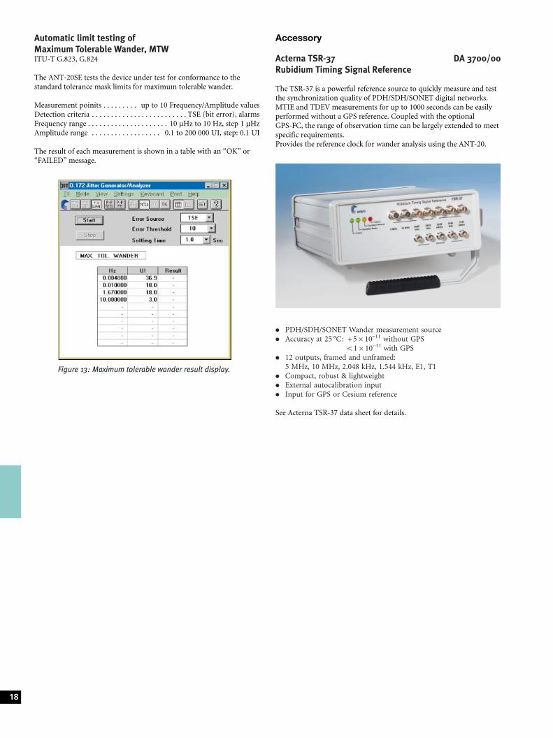
Automatic limit testing ofMaximum Tolerable Wander, MTWITU-T G.823, G.824
The ANT-20SE tests the device under test for conformance to thestandard tolerance mask limits for maximum tolerable wander.
Measurement poinits . . . . . . . . . up to 10 Frequency/Amplitude valuesDetection criteria . . . . . . . . . . . . . . . . . . . . . . . . . TSE (bit error), alarmsFrequency range . . . . . . . . . . . . . . . . . . . . . 10 mHz to 10 Hz, step 1 mHzAmplitude range . . . . . . . . . . . . . . . . . . 0.1 to 200 000 UI, step: 0.1 UI
The result of each measurement is shown in a table with an ªOKº orªFAILEDº message.
Accessory
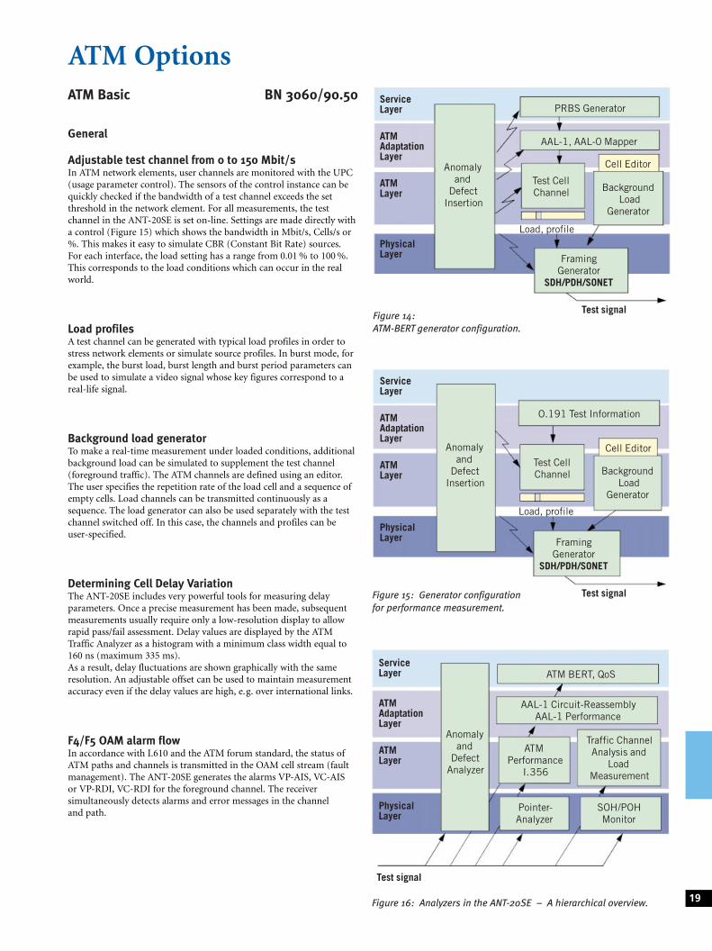
Acterna TSR-37 DA 3700/00Rubidium Timing Signal Reference
The TSR-37 is a powerful reference source to quickly measure and testthe synchronization quality of PDH/SDH/SONET digital networks.MTIE and TDEV measurements for up to 1000 seconds can be easilyperformed without a GPS reference. Coupled with the optionalGPS-FC, the range of observation time can be largely extended to meetspecific requirements.Provides the reference clock for wander analysis using the ANT-20.
. PDH/SDH/SONET Wander measurement source
. Accuracy at 25 �C: +5610±11 without GPS51610±11 with GPS
. 12 outputs, framed and unframed:5 MHz, 10 MHz, 2.048 kHz, 1.544 kHz, E1, T1
. Compact, robust & lightweight
. External autocalibration input
. Input for GPS or Cesium reference
See Acterna TSR-37 data sheet for details.
18
Figure 13: Maximum tolerable wander result display.
ServiceLayer
ATMAdaptationLayer
ATMLayer
PhysicalLayer
Anomalyand
DefectInsertion
PRBS Generator
Test CellChannel
Cell Editor
BackgroundLoad
Generator
Load, profile
Test signal
AAL-1, AAL-0 Mapper
FramingGenerator
SDH/PDH/SONET
Figure 14:ATM-BERT generator configuration.
ServiceLayer
ATMAdaptationLayer
ATMLayer
PhysicalLayer
Anomalyand
DefectInsertion
Test CellChannel
Cell Editor
BackgroundLoad
Generator
Load, profile
Test signal
O.191 Test Information
FramingGenerator
SDH/PDH/SONET
Figure 15: Generator configurationfor performance measurement.
ServiceLayer
ATMAdaptationLayer
ATMLayer
PhysicalLayer
Anomalyand
DefectAnalyzer
ATM BERT, QoS
AAL-1 Circuit-ReassemblyAAL-1 Performance
ATMPerformance
I.356
Traffic ChannelAnalysis and
LoadMeasurement
Pointer-Analyzer
SOH/POHMonitor
Test signal
Figure 16: Analyzers in the ANT-20SE ± A hierarchical overview.
ATM OptionsATM Basic BN 3060/90.50
General
Adjustable test channel from 0 to 150 Mbit/sIn ATM network elements, user channels are monitored with the UPC(usage parameter control). The sensors of the control instance can bequickly checked if the bandwidth of a test channel exceeds the setthreshold in the network element. For all measurements, the testchannel in the ANT-20SE is set on-line. Settings are made directly witha control (Figure 15) which shows the bandwidth in Mbit/s, Cells/s or%. This makes it easy to simulate CBR (Constant Bit Rate) sources.For each interface, the load setting has a range from 0.01 % to 100 %.This corresponds to the load conditions which can occur in the realworld.
Load profilesA test channel can be generated with typical load profiles in order tostress network elements or simulate source profiles. In burst mode, forexample, the burst load, burst length and burst period parameters canbe used to simulate a video signal whose key figures correspond to areal-life signal.
Background load generatorTo make a real-time measurement under loaded conditions, additionalbackground load can be simulated to supplement the test channel(foreground traffic). The ATM channels are defined using an editor.The user specifies the repetition rate of the load cell and a sequence ofempty cells. Load channels can be transmitted continuously as asequence. The load generator can also be used separately with the testchannel switched off. In this case, the channels and profiles can beuser-specified.
Determining Cell Delay VariationThe ANT-20SE includes very powerful tools for measuring delayparameters. Once a precise measurement has been made, subsequentmeasurements usually require only a low-resolution display to allowrapid pass/fail assessment. Delay values are displayed by the ATMTraffic Analyzer as a histogram with a minimum class width equal to160 ns (maximum 335 ms).As a result, delay fluctuations are shown graphically with the sameresolution. An adjustable offset can be used to maintain measurementaccuracy even if the delay values are high, e.g. over international links.
F4/F5 OAM alarm flowIn accordance with I.610 and the ATM forum standard, the status ofATM paths and channels is transmitted in the OAM cell stream (faultmanagement). The ANT-20SE generates the alarms VP-AIS, VC-AISor VP-RDI, VC-RDI for the foreground channel. The receiversimultaneously detects alarms and error messages in the channeland path.
19
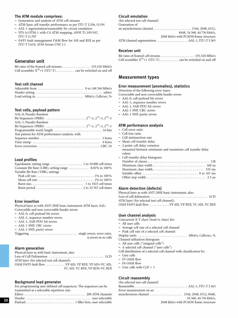
The ATM module comprises:± Generation and analysis of ATM cell streams± ATM layer cell transfer performance as per ITU-T I.356, O.191± AAL-1 segmentation/reassembly for circuit emulation± STS-3c/STM-1 with C4 ATM mapping, ANSI T1.105/107,
ITU-T G.707± F4/F5 fault management OAM flow for AIS and RDI as per
ITU-T I.610, ATM forum UNI 3.1
Generator unitBit rates of the framed cell streams . . . . . . . . . . . . . . . . . 155.520 Mbit/sCell scrambler X43+1 (ITU-T) . . . . . . . . . . . can be switched on and off
Test cell channelAdjustable from . . . . . . . . . . . . . . . . . . . . . . . . . . . . 0 to 149.760 Mbit/sHeader setting . . . . . . . . . . . . . . . . . . . . . . . . . . . . . . . . . . . . . . . . editorLoad setting in . . . . . . . . . . . . . . . . . . . . . . . . . . . . . Mbit/s, Cells/sec, %
Test cells, payload patternAAL-0, Pseudo-RandomBit Sequences (PRBS) . . . . . . . . . . . . . . . . . . . . . . . . 211±1, 215±1, 223±1AAL-1, Pseudo-RandomBit Sequences (PRBS) . . . . . . . . . . . . . . . . . . . . . . . . 211±1, 215±1, 223±1Programmable word, length . . . . . . . . . . . . . . . . . . . . . . . . . . . . . 16 bitsTest pattern for ATM performance analysis, withSequence number . . . . . . . . . . . . . . . . . . . . . . . . . . . . . . . . . . . . . 3 bytesTime stamp . . . . . . . . . . . . . . . . . . . . . . . . . . . . . . . . . . . . . . . . . 4 bytesError correction . . . . . . . . . . . . . . . . . . . . . . . . . . . . . . . . . . . . . . CRC-16
Load profilesEquidistant, setting range . . . . . . . . . . . . . . . . . . . 1 to 10 000 cell timesConstant Bit Rate (CBR), setting range . . . . . . . . . . . . 0.01% to 100 %Variable Bit Rate (VBR), settings
Peak cell rate . . . . . . . . . . . . . . . . . . . . . . . . . . . . . . . . . . . 1% to 100 %Mean cell rate . . . . . . . . . . . . . . . . . . . . . . . . . . . . . . . . . . 1% to 100 %Burst size. . . . . . . . . . . . . . . . . . . . . . . . . . . . . . . . 1 to 1023 cell timesBurst period . . . . . . . . . . . . . . . . . . . . . . . . . . . . 2 to 32 767 cell times
Error insertionPhysical layer as with ANT-20SE basic instrument ATM layer, AAL:Correctable and non-correctable header errors± AAL-0, cell payload bit errors± AAL-1, sequence number errors± AAL-1, SAR-PDU bit errors± AAL-1 SNP, CRC errors± AAL-1 SNP, parity errorsTriggering . . . . . . . . . . . . . . . . . . . . . . . . . . . . . single errors, error ratio,
n errors in m cells
Alarm generationPhysical layer as with basic instrument, also:Loss of Cell Delineation . . . . . . . . . . . . . . . . . . . . . . . . . . . . . . . . . LCDATM layer (for selected test cell channel):OAM F4/F5 fault flow . . . . . . . . . . . .VP AIS, VP RDI, VP AIS+VC AIS,
VC AIS, VC RDI, VP RDI+VC RDI
Background load generatorFor programming user-defined cell sequences. The sequences can betransmitted at a selectable repetition rate.Editor . . . . . . . . . . . . . . . . . . . . . . . . . . . . . . . . . . . . . 200 ATM channelsHeader . . . . . . . . . . . . . . . . . . . . . . . . . . . . . . . . . . . . . . . user-selectablePayload . . . . . . . . . . . . . . . . . . . . . . . . . . . . . 1 filler byte, user-selectable
Circuit emulation(for selected test cell channel)Generation ofan asynchronous channel . . . . . . . . . . . . . . . . . . . . . . . 1544, 2048, 6312,
8448, 34 368, 44 736 kbit/s,2048 kbit/s with PCM30 frame structure
ATM channel segmentation . . . . . . . . . . . . . . . . . . . AAL-1, ITU-T I.363
Receiver unitBit rates of framed cell streams . . . . . . . . . . . . . . . . . . . . 155.520 Mbit/sCell scrambler X43+1 (ITU-T) . . . . . . . . . . . can be switched on and off
Measurement types
Error measurement (anomalies), statisticsDetection of the following error types:Correctable and non-correctable header errors± AAL-0, cell payload bit errors± AAL-1, sequence number errors± AAL-1, SAR-PDU bit errors± AAL-1 SNP, CRC errors± AAL-1 SNP, parity errors
ATM performance analysis± Cell error ratio± Cell loss ratio± Cell misinsertion rate± Mean cell transfer delay± 2-point cell delay variation
measured between minimum and maximum cell transfer delayvalues
± Cell transfer delay histogramNumber of classes . . . . . . . . . . . . . . . . . . . . . . . . . . . . . . . . . . 128Minimum class width . . . . . . . . . . . . . . . . . . . . . . . . . . . . . 160 nsMaximum class width . . . . . . . . . . . . . . . . . . . . . . . . . . . . 335 msSettable offset . . . . . . . . . . . . . . . . . . . . . . . . . . . . . . . 0 to 167 msOffset step width. . . . . . . . . . . . . . . . . . . . . . . . . . . . . . . . . 2.5 ms
Alarm detection (defects)Physical layer as with ANT-20SE basic instrument, also:Loss of cell delineation . . . . . . . . . . . . . . . . . . . . . . . . . . . . . . . . . . . LCDATM layer (for selected test cell channel):OAM F4/F5 fault flow . . . . . . . . . . . .VP AIS, VP RDI, VC AIS, VC RDI
User channel analysisConcurrent X-Y chart (load vs. time) for:± All user cells± Average cell rate of a selected cell channel± Peak cell rate of a selected cell channelDisplay units . . . . . . . . . . . . . . . . . . . . . . . . . . . . . . Mbit/s, Cells/sec, %Channel utilization histogram± All user cells (ªassigned cellsº)± A selected cell channel (ªuser cellsº)Cell distribution of a selected cell channel with classification by:± User cells± F5 OAM flow± F4 OAM flow± User cells with CLP = 1
Circuit reassembly(for selected test cell channel)Reassembly . . . . . . . . . . . . . . . . . . . . . . . . . . . . . . . . AAL-1, ITU-T I.363Error measurement on anasynchronous channel . . . . . . . . . . . . . . . . . . . . 1544, 2048, 6312, 8448,
34 368, 44 736 kbit/s,2048 kbit/s with PCM30 frame structure20
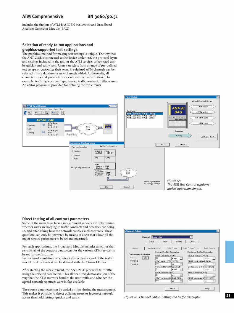
Figure 17:The ATM Test Control windowsmakes operation simple.
ATM Comprehensive BN 3060/90.51
includes the fuction of ATM BASIC BN 3060/90.50 and BroadbandAnalyzer Generator Module (BAG)
Selection of ready-to-run applications andgraphics-supported test settingsThe graphical method for making test settings is unique. The way thatthe ANT-20SE is connected to the device under test, the protocol layersand settings included in the test, or the ATM services to be tested canbe quickly and easily seen. Users can select from a range of pre-definedtest setups or customize their own. Pre-defined ATM channels can beselected from a database or new channels added. Additionally, allcharacteristics and parameters for each channel are also stored, forexample: traffic type, circuit type, header, traffic contract, traffic source.An editor program is provided for defining the test circuits.
Direct testing of all contract parametersSome of the main tasks facing measurement services are determiningwhether users are keeping to traffic contracts and how they are doingso, and establishing how the network handles such contracts. Thesequestions can only be answered by means of a test that allows all themajor service parameters to be set and measured.
For such applications, the Broadband Module includes an editor thatpermits all of the contract parameters for the various ATM services tobe set for the first time.For terminal emulation, all contract characteristics and of the trafficmodel used for the test can be defined with the Channel Editor.
After starting the measurement, the ANT-20SE generates test trafficusing the selected parameters. This allows direct demonstration of theway that the ATM network handles the user traffic and whether theagreed network resources were in fact available.
The source parameters can be varied on-line during the measurement.This makes it possible to detect policing errors or incorrect networkaccess threshold settings quickly and easily. 21Figure 18: Channel Editor: Setting the traffic descriptor.
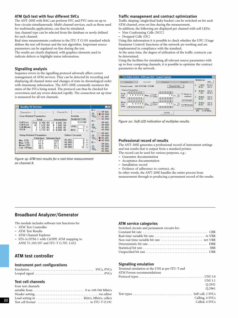
ATM QoS test with four different SVCsThe ANT-20SE with BAG can perform SVC and PVC tests on up tofour circuits simultaneously. Multi-channel services, such as those usedfor multimedia applications, can thus be simulated.Any channel type can be selected from the database or newly definedfor each channel.Real-time measurements conform to the ITU-T O.191 standard whichdefines the test cell format and the test algorithm. Important sourceparameters can be regulated on-line during the test.The results are clearly displayed, with graphics elements used toindicate defects or highlight status information.
Signalling analysisSequence errors in the signalling protocol adversely affect correctmanagement of ATM services. They can be detected by recording anddisplaying all channel states and changes of state in chronological orderwith timestamp information. The ANT-20SE constantly monitors thestates of the SVCs being tested. The protocol can thus be checked forcorrectness and any errors detected rapidly. The connection set up timeis measured for all test channels.
Traffic management and contract optimizationTraffic shaping (single/dual leaky bucket) can be switched on for eachATM channel, even on-line during the measurement.In addition, the following are displayed per channel with soft LEDs:± Non Conforming Cells (NCC)± Dropped Cells (DC)Using this information it is possible to check whether the UPC (UsageParameter Control) functions of the network are working and areimplemented in compliance with the standard.At the same time, the degree of utilization of the traffic contracts canbe determined.Using the facilities for simulating all relevant source parameters withup to four competing channels, it is possible to optimize the contractparameters in the network.
Professional record of resultsThe ANT-20SE generates a professional record of instrument settingsand test results that is output from a standard printer.The record can be used for various purposes, e.g.:± Guarantee documentation± Acceptance documentation± Installation record± Evidence of adherence to contract, etc.In other words, the ANT-20SE handles the entire process frommeasurement through to producing a permanent record of the results.
22
Figure 20: Soft-LED indication of multiplex results.
Figure 19: ATM test results for a real-time measurementon channel A.
Broadband Analyzer/Generator
The module includes software test functions for± ATM Test Controller± ATM Test Results± ATM Channel Explorer± STS-3c/STM-1 with C4/SPE ATM mapping to
ANSI T1.105/107 and ITU-T G.707, I.432
ATM test controller
Instrument port configurationsEmulation . . . . . . . . . . . . . . . . . . . . . . . . . . . . . . . . . . . . . . . SVCs, PVCsLooped signal . . . . . . . . . . . . . . . . . . . . . . . . . . . . . . . . . . . . . . . . . . PVCs
Test cell channelsFour test channelssettable from . . . . . . . . . . . . . . . . . . . . . . . . . . . . . . 0 to 149.760 Mbit/sHeader setting. . . . . . . . . . . . . . . . . . . . . . . . . . . . . . . . . . . . . . . via editorLoad setting in . . . . . . . . . . . . . . . . . . . . . . . . . . . . kbit/s, Mbit/s, cells/sTest cell format . . . . . . . . . . . . . . . . . . . . . . . . . . . . . . . to ITU-T O.191
ATM service categoriesSwitched circuits and permanent circuits for:Constant bit rate . . . . . . . . . . . . . . . . . . . . . . . . . . . . . . . . . . . . . . . CBRReal-time variable bit rate . . . . . . . . . . . . . . . . . . . . . . . . . . . . . . rt-VBRNon real-time variable bit rate . . . . . . . . . . . . . . . . . . . . . . . . . nrt-VBRDeterministic bit rate . . . . . . . . . . . . . . . . . . . . . . . . . . . . . . . . . . . . DBRStatistical bit rate . . . . . . . . . . . . . . . . . . . . . . . . . . . . . . . . . . . . . . . . SBRUnspecified bit rate . . . . . . . . . . . . . . . . . . . . . . . . . . . . . . . . . . . . . UBR
Signalling emulationTerminal emulation at the UNI as per ITU-T andATM Forum recommendationsProtocol types . . . . . . . . . . . . . . . . . . . . . . . . . . . . . . . . . . . . . . . . UNI 3.0
UNI 3.1Q.2931Q.2961
Test types. . . . . . . . . . . . . . . . . . . . . . . . . . . . . . . . . . . . . Self-call, 2 SVCsCalling, 4 SVCsCalled, 4 SVCs
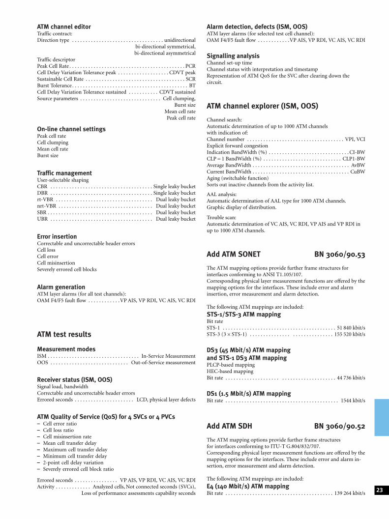
ATM channel editorTraffic contract:Direction type . . . . . . . . . . . . . . . . . . . . . . . . . . . . . . . . . . unidirectional
bi-directional symmetrical,bi-directional asymmetrical
Traffic descriptorPeak Cell Rate . . . . . . . . . . . . . . . . . . . . . . . . . . . . . . . . . . . . . . . . . . . PCRCell Delay Variation Tolerance peak . . . . . . . . . . . . . . . . . . . CDVT peakSustainable Cell Rate . . . . . . . . . . . . . . . . . . . . . . . . . . . . . . . . . . . . . SCRBurst Tolerance . . . . . . . . . . . . . . . . . . . . . . . . . . . . . . . . . . . . . . . . . . . BTCell Delay Variation Tolerance sustained . . . . . . . . . . . CDVT sustainedSource parameters . . . . . . . . . . . . . . . . . . . . . . . . . . . . . . Cell clumping,
Burst sizeMean cell ratePeak cell rate
On-line channel settingsPeak cell rateCell clumpingMean cell rateBurst size
Traffic managementUser-selectable shapingCBR . . . . . . . . . . . . . . . . . . . . . . . . . . . . . . . . . . . . . . Single leaky bucketDBR . . . . . . . . . . . . . . . . . . . . . . . . . . . . . . . . . . . . . . Single leaky bucketrt-VBR . . . . . . . . . . . . . . . . . . . . . . . . . . . . . . . . . . . . Dual leaky bucketnrt-VBR . . . . . . . . . . . . . . . . . . . . . . . . . . . . . . . . . . . Dual leaky bucketSBR . . . . . . . . . . . . . . . . . . . . . . . . . . . . . . . . . . . . . . . Dual leaky bucketUBR . . . . . . . . . . . . . . . . . . . . . . . . . . . . . . . . . . . . . . Dual leaky bucket
Error insertionCorrectable and uncorrectable header errorsCell lossCell errorCell misinsertionSeverely errored cell blocks
Alarm generationATM layer alarms (for all test channels):OAM F4/F5 fault flow . . . . . . . . . . . .VP AIS, VP RDI, VC AIS, VC RDI
ATM test results
Measurement modesISM . . . . . . . . . . . . . . . . . . . . . . . . . . . . . . . . . . In-Service MeasurementOOS . . . . . . . . . . . . . . . . . . . . . . . . . . . . . Out-of-Service measurement
Receiver status (ISM, OOS)Signal load, bandwidthCorrectable and uncorrectable header errorsErrored seconds . . . . . . . . . . . . . . . . . . . . . . LCD, physical layer defects
ATM Quality of Service (QoS) for 4 SVCs or 4 PVCs± Cell error ratio± Cell loss ratio± Cell misinsertion rate± Mean cell transfer delay± Maximum cell transfer delay± Minimum cell transfer delay± 2-point cell delay variation± Severely errored cell block ratio
Errored seconds . . . . . . . . . . . . . . . . VP AIS, VP RDI, VC AIS, VC RDIActivity . . . . . . . . . . . . . Analyzed cells, Not connected seconds (SVCs),
Loss of performance assessments capability seconds
Alarm detection, defects (ISM, OOS)ATM layer alarms (for selected test cell channel):OAM F4/F5 fault flow . . . . . . . . . . . .VP AIS, VP RDI, VC AIS, VC RDI
Signalling analysisChannel set-up timeChannel status with interpretation and timestampRepresentation of ATM QoS for the SVC after clearing down thecircuit.
ATM channel explorer (ISM, OOS)
Channel search:Automatic determination of up to 1000 ATM channelswith indication of:Channel number . . . . . . . . . . . . . . . . . . . . . . . . . . . . . . . . . . . . VPI, VCIExplicit forward congestionIndication BandWidth (%) . . . . . . . . . . . . . . . . . . . . . . . . . . . . . . CI-BWCLP = 1 BandWidth (%) . . . . . . . . . . . . . . . . . . . . . . . . . . . . . CLP1-BWAverage BandWidth . . . . . . . . . . . . . . . . . . . . . . . . . . . . . . . . . . . . AvBWCurrent BandWidth . . . . . . . . . . . . . . . . . . . . . . . . . . . . . . . . . . . . CuBWAging (switchable function)Sorts out inactive channels from the activity list.
AAL analysis:Automatic determination of AAL type for 1000 ATM channels.Graphic display of distribution.
Trouble scan:Automatic determination of VC AIS, VC RDI, VP AIS and VP RDI inup to 1000 ATM channels.
Add ATM SONET BN 3060/90.53
The ATM mapping options provide further frame structures forinterfaces conforming to ANSI T1.105/107.Corresponding physical layer measurement functions are offered by themapping options for the interfaces. These include error and alarminsertion, error measurement and alarm detection.
The following ATM mappings are included:
STS-1/STS-3 ATM mappingBit rateSTS-1 . . . . . . . . . . . . . . . . . . . . . . . . . . . . . . . . . . . . . . . . . . 51 840 kbit/sSTS-3 (36STS-1) . . . . . . . . . . . . . . . . . . . . . . . . . . . . . . 155 520 kbit/s
DS3 (45 Mbit/s) ATM mappingand STS-1 DS3 ATM mappingPLCP-based mappingHEC-based mappingBit rate . . . . . . . . . . . . . . . . . . . . . . . . . . . . . . . . . . . . . . . . 44 736 kbit/s
DS1 (1.5 Mbit/s) ATM mappingBit rate . . . . . . . . . . . . . . . . . . . . . . . . . . . . . . . . . . . . . . . . . . 1544 kbit/s
Add ATM SDH BN 3060/90.52
The ATM mapping options provide further frame structuresfor interfaces conforming to ITU-T G.804/832/707.Corresponding physical layer measurement functions are offered by themapping options for the interfaces. These include error and alarm in-sertion, error measurement and alarm detection.
The following ATM mappings are included:
E4 (140 Mbit/s) ATM mappingBit rate . . . . . . . . . . . . . . . . . . . . . . . . . . . . . . . . . . . . . . . . 139 264 kbit/s 23
E3 (34 Mbit/s) ATM mappingBit rate . . . . . . . . . . . . . . . . . . . . . . . . . . . . . . . . . . . . . . . . 34 368 kbit/s
E1 (2 Mbit/s) ATM mappingBit rate . . . . . . . . . . . . . . . . . . . . . . . . . . . . . . . . . . . . . . . . . . 2048 kbit/s
STM-1/VC3 ATM mappingBit rate . . . . . . . . . . . . . . . . . . . . . . . . . . . . . . . . . . . . . . . . 155 520 kbit/s
OC-12c/STM-4c ATM testing BN 3060/90.91
Only in conjunction with BN 3060/90.50 and BN 3060/91.11 orBN 3060/91.12
Signal structure (TC sublayer) contiguous concatenation to T1.646,I.432 and af-phy-0046.000Cell scrambler X43+1 (ITU-T) . . . . . . . . . . . . . . . . can be switched off
Test cell channelAdjustable from . . . . . . . . . . . . . . . . . . . . . . . . . . . . 0 to 149.760 Mbit/sHeader setting . . . . . . . . . . . . . . . . . . . . . . . . . . . . . . . . . . . . . . . . editorLoad setting in . . . . . . . . . . . . . . . . . . . . . . . . . . . . Mbit/s, Cells/sec, %
Test cells, pay load patternAAL-0, pseudorandom bit sequences(PRBS) . . . . . . . . . . . . . . . . . . . . . . . . . . . . . . . . . . . . 211±1, 215±1, 223±1AAL-1, pseudorandom bit sequences(PRBS) . . . . . . . . . . . . . . . . . . . . . . . . . . . . . . . . . . . . 211±1, 215±1, 223±1Programmable word, length . . . . . . . . . . . . . . . . . . . . . . . . . . . . . 16 bitsTest cells for ATM performance analysis:Sequence number . . . . . . . . . . . . . . . . . . . . . . . . . . . . . . . . . . . . . . 3 bytesTimestamp . . . . . . . . . . . . . . . . . . . . . . . . . . . . . . . . . . . . . . . . . . . 4 bytesError checking . . . . . . . . . . . . . . . . . . . . . . . . . . . . . . . . . . . . . . . CRC-16
Load profilesEquidistant, setting range . . . . . . . . . . . . . . . . 4 to 40 000 cell times +1Constant Bit Rate (CBR), setting range . . . . . . . . . . . . . . 0.01% to 25%Variable Bit Rate (VBR), settings
Peak cell rate . . . . . . . . . . . . . . . . . . . . . . . . . . . . . . . . . . . .1% to 25%Mean cell rate . . . . . . . . . . . . . . . . . . . . . . . . . . . . . . . . . . 1% to 25%Burst size . . . . . . . . . . . . . . . . . . . . . . . . . . . . . . . 4 to 4092 cell timesBurst period . . . . . . . . . . . . . . . . . . . . . . . . . . . 8 to 131 068 cell times
Error insertionPhysical layer like basic ANT-20SE instrumentATM layer, AAL:Correctable and non-correctable header errorsAAL-0, cell payload bit errorAAL-1, sequence number errorAAL-1, SAR-PDU bit errorAAL-1 SNP, CRC errorAAL-1 SNP, parity errorResolution:Single error, error ratio, M errors in N cells
Alarm generationLoss of Cell Delineation . . . . . . . . . . . . . . . . . . . . . . . . . . . . . . . . . LCDATM layer (for any selected cell channel):OAM F4/F5 fault flow:VP AIS, VP RDI, VP AIS+VC AISVC AIS, VC RDI, VP RDI+VC RDI
Background load generator1 ATM channel can be switched ON/OFFHeader. . . . . . . . . . . . . . . . . . . . . . . . . . . . . . . . . . . . . . . . freely definablePayload . . . . . . . . . . . . . . . . . . . . . . . . . . . . . . . . 1 fill byte freely settableCBR . . . . . . . . . . . . . . . . . . . . . . . . . . . . . . . . . . . . . . . . . . . . 449 Mbit/s
Circuit emulationGeneration of asynchronous channels:1.544, 2.048, 6.312, 8.448, 34.368, 44.736 kbit/s,2.048 kbit/s with PCM30 frame structureATM channel segmentation . . . . . . . . . . . . . . . . . . AAL-1, ITU-T I.363
Error measurement, anomalies, statisticsDetection of following error types:Correctable and non-correctable header errorsAAL-0, cell payload bit errorAAL-1, sequence number errorAAL-1, SAR-PDU bit errorAAL-1 SNP, CRC errorAAL-1 SNP, parity error
ATM performance analysis± Cell error ratio± Cell loss ratio± Cell misinsertion rate± Mean cell transfer delay± 2-point cell delay variation
Measured between greatest and smallest value of cell transfer delay± Cell transfer delay histogram:Number of classes. . . . . . . . . . . . . . . . . . . . . . . . . . . . . . . . . . . . . . . . 128Min. class width . . . . . . . . . . . . . . . . . . . . . . . . . . . . . . . . . . . . . . . 160 nsMax. class width . . . . . . . . . . . . . . . . . . . . . . . . . . . . . . . . . . . . . . 335 msAdjustable offset . . . . . . . . . . . . . . . . . . . . . . . . . . . . . . . . . . . 0 to 167 msOffset steps . . . . . . . . . . . . . . . . . . . . . . . . . . . . . . . . . . . . . . . . . . . 2.5 ms
Alarm detection, defects (ISM, OoS)Loss of Cell Delineation . . . . . . . . . . . . . . . . . . . . . . . . . . . . . . . . . . LCDATM layer (for any selected cell channel):OAM F4/F5 fault flow:VP AIS, VP RDI, VC AIS, VC RDI
Traffic channel analysisTime chart simultaneously for± All traffic cells± Average cell rate of any selected cell channel± Peak cell rate of any selected cell channelDisplay in . . . . . . . . . . . . . . . . . . . . . . . . . . . . . . . . . Mbit/s, Cells/sec, %
Channel utilization histogram± All assigned cells± One selected cell channel (user cells)
Cell distribution in traffic channelClassification of one selected cell channel by± User cells± F5 OAM flow± F4 OAM flow± User cells with CLP = 1
Circuit reassemblyReassembly . . . . . . . . . . . . . . . . . . . . . . . . . . . . . . . . AAL-1, ITU-T I.363Error measurement on asynchronous channels:1.544, 2.048, 6.312, 8.448, 34.368, 44.736 kbit/s, 2.048 kbit/s withPCM30 frame structure
24
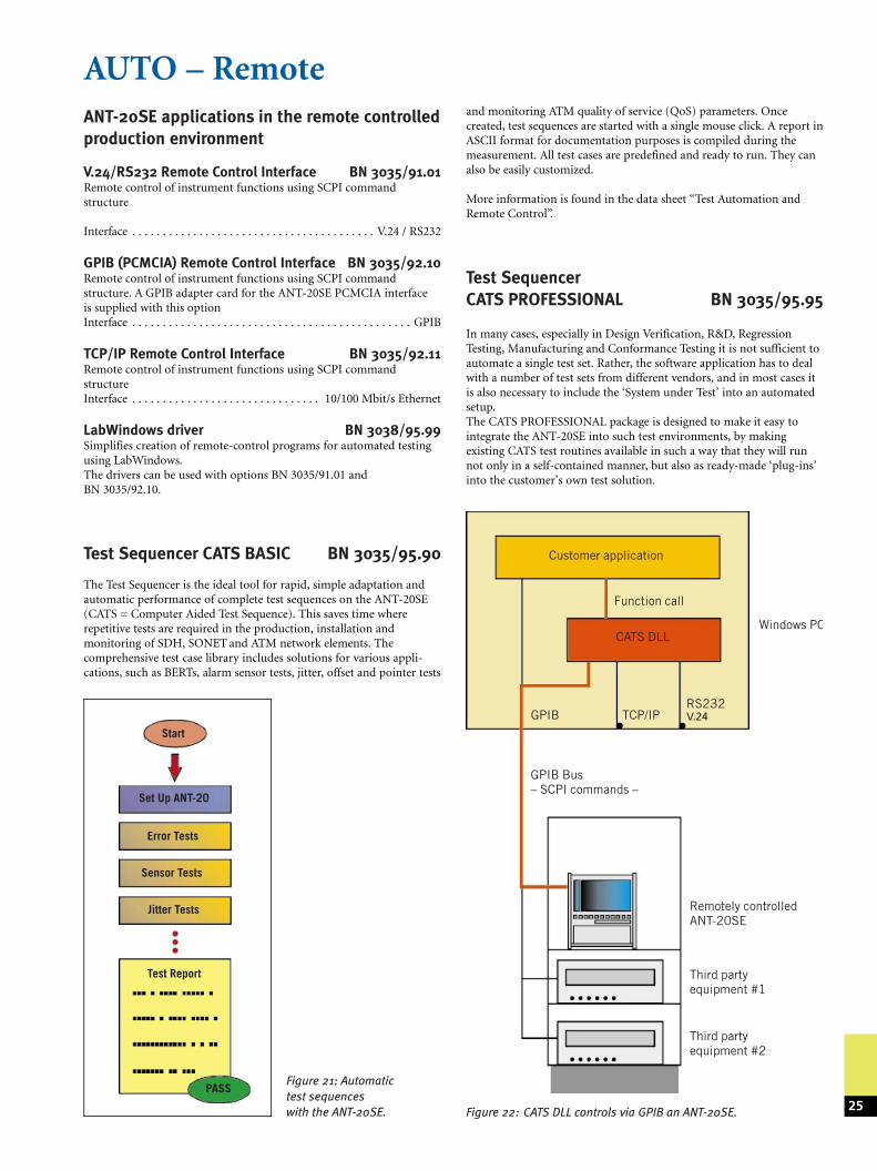
AUTO ± RemoteANT-20SE applications in the remote controlledproduction environment
V.24/RS232 Remote Control Interface BN 3035/91.01Remote control of instrument functions using SCPI commandstructure
Interface . . . . . . . . . . . . . . . . . . . . . . . . . . . . . . . . . . . . . . . . V.24 / RS232
GPIB (PCMCIA) Remote Control Interface BN 3035/92.10Remote control of instrument functions using SCPI commandstructure. A GPIB adapter card for the ANT-20SE PCMCIA interfaceis supplied with this optionInterface . . . . . . . . . . . . . . . . . . . . . . . . . . . . . . . . . . . . . . . . . . . . . . GPIB
TCP/IP Remote Control Interface BN 3035/92.11Remote control of instrument functions using SCPI commandstructureInterface . . . . . . . . . . . . . . . . . . . . . . . . . . . . . . . 10/100 Mbit/s Ethernet
LabWindows driver BN 3038/95.99Simplifies creation of remote-control programs for automated testingusing LabWindows.The drivers can be used with options BN 3035/91.01 andBN 3035/92.10.
Test Sequencer CATS BASIC BN 3035/95.90
The Test Sequencer is the ideal tool for rapid, simple adaptation andautomatic performance of complete test sequences on the ANT-20SE(CATS = Computer Aided Test Sequence). This saves time whererepetitive tests are required in the production, installation andmonitoring of SDH, SONET and ATM network elements. Thecomprehensive test case library includes solutions for various appli-cations, such as BERTs, alarm sensor tests, jitter, offset and pointer tests
and monitoring ATM quality of service (QoS) parameters. Oncecreated, test sequences are started with a single mouse click. A report inASCII format for documentation purposes is compiled during themeasurement. All test cases are predefined and ready to run. They canalso be easily customized.
More information is found in the data sheet ªTest Automation andRemote Controlº.
Test SequencerCATS PROFESSIONAL BN 3035/95.95
In many cases, especially in Design Verification, R&D, RegressionTesting, Manufacturing and Conformance Testing it is not sufficient toautomate a single test set. Rather, the software application has to dealwith a number of test sets from different vendors, and in most cases itis also necessary to include the `System under Test' into an automatedsetup.The CATS PROFESSIONAL package is designed to make it easy tointegrate the ANT-20SE into such test environments, by makingexisting CATS test routines available in such a way that they will runnot only in a self-contained manner, but also as ready-made `plug-ins'into the customer's own test solution.
25
Start
Error Tests
Sensor Tests
Jitter Tests
Test Report
PASS
Set Up ANT-20
Figure 21: Automatictest sequenceswith the ANT-20SE.
Windows PC
Customer application
CATS DLL
GPIB TCP/IPRS232V.24
GPIB Bus± SCPI commands ±
Remotely controlledANT-20SE
Third partyequipment #1
Third partyequipment #2
Function call
Figure 22: CATS DLL controls via GPIB an ANT-20SE.
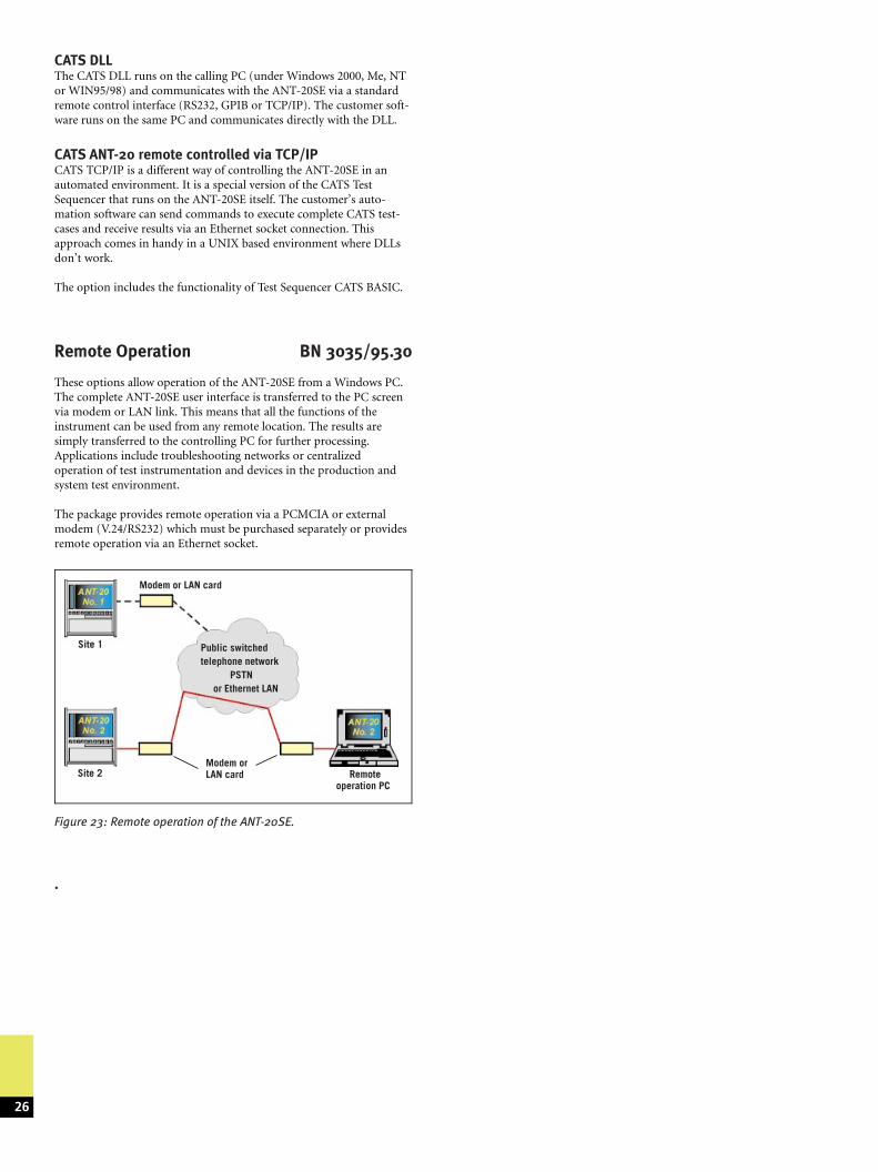
Figure 23: Remote operation of the ANT-20SE.
CATS DLLThe CATS DLL runs on the calling PC (under Windows 2000, Me, NTor WIN95/98) and communicates with the ANT-20SE via a standardremote control interface (RS232, GPIB or TCP/IP). The customer soft-ware runs on the same PC and communicates directly with the DLL.
CATS ANT-20 remote controlled via TCP/IPCATS TCP/IP is a different way of controlling the ANT-20SE in anautomated environment. It is a special version of the CATS TestSequencer that runs on the ANT-20SE itself. The customer's auto-mation software can send commands to execute complete CATS test-cases and receive results via an Ethernet socket connection. Thisapproach comes in handy in a UNIX based environment where DLLsdon't work.
The option includes the functionality of Test Sequencer CATS BASIC.
Remote Operation BN 3035/95.30
These options allow operation of the ANT-20SE from a Windows PC.The complete ANT-20SE user interface is transferred to the PC screenvia modem or LAN link. This means that all the functions of theinstrument can be used from any remote location. The results aresimply transferred to the controlling PC for further processing.Applications include troubleshooting networks or centralizedoperation of test instrumentation and devices in the production andsystem test environment.
The package provides remote operation via a PCMCIA or externalmodem (V.24/RS232) which must be purchased separately or providesremote operation via an Ethernet socket.
.
26
Modem or LAN card
Modem orLAN card
Public switchedtelephone network
PSTNor Ethernet LAN
Site 1
Site 2 Remoteoperation PC
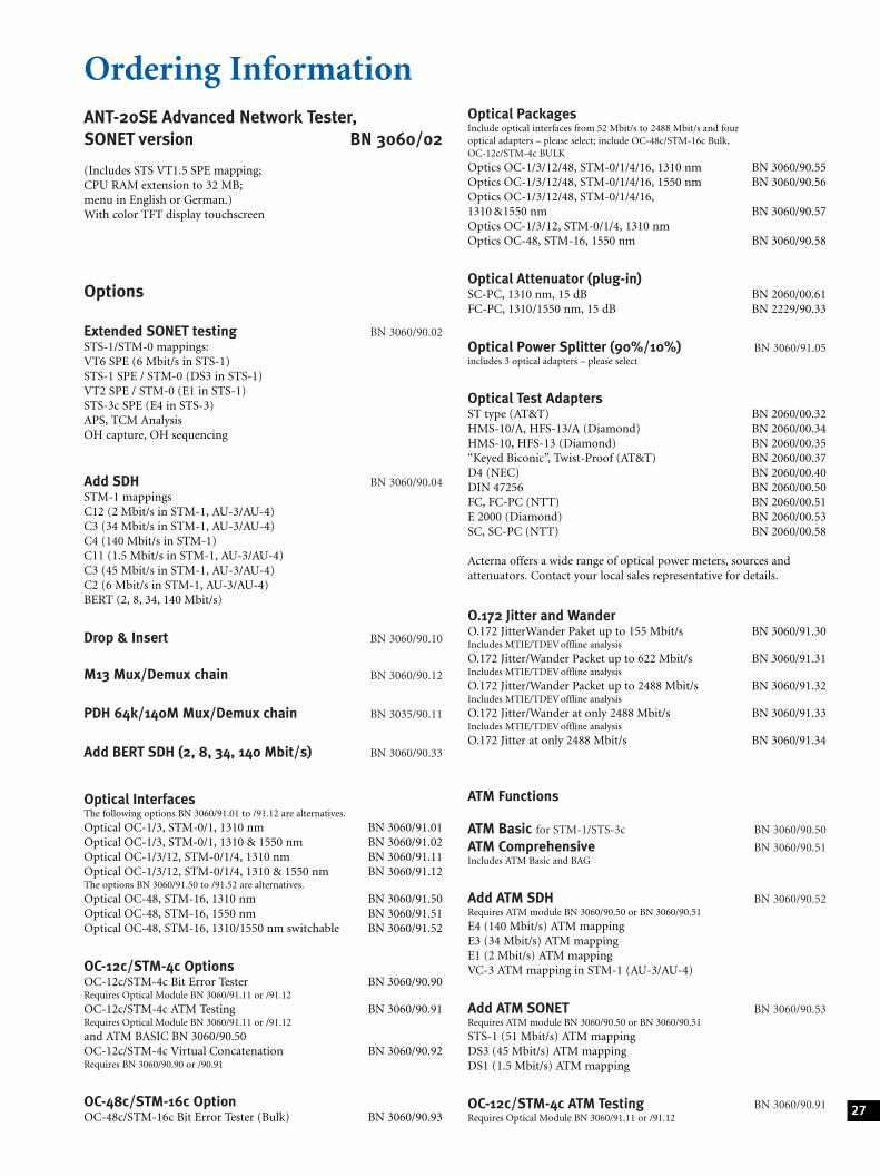
Ordering InformationANT-20SE Advanced Network Tester,SONET version BN 3060/02
(Includes STS VT1.5 SPE mapping;CPU RAM extension to 32 MB;menu in English or German.)With color TFT display touchscreen
Options
Extended SONET testing BN 3060/90.02STS-1/STM-0 mappings:VT6 SPE (6 Mbit/s in STS-1)STS-1 SPE / STM-0 (DS3 in STS-1)VT2 SPE / STM-0 (E1 in STS-1)STS-3c SPE (E4 in STS-3)APS, TCM AnalysisOH capture, OH sequencing
Add SDH BN 3060/90.04STM-1 mappingsC12 (2 Mbit/s in STM-1, AU-3/AU-4)C3 (34 Mbit/s in STM-1, AU-3/AU-4)C4 (140 Mbit/s in STM-1)C11 (1.5 Mbit/s in STM-1, AU-3/AU-4)C3 (45 Mbit/s in STM-1, AU-3/AU-4)C2 (6 Mbit/s in STM-1, AU-3/AU-4)BERT (2, 8, 34, 140 Mbit/s)
Drop & Insert BN 3060/90.10
M13 Mux/Demux chain BN 3060/90.12
PDH 64k/140M Mux/Demux chain BN 3035/90.11
Add BERT SDH (2, 8, 34, 140 Mbit/s) BN 3060/90.33
Optical InterfacesThe following options BN 3060/91.01 to /91.12 are alternatives.
Optical OC-1/3, STM-0/1, 1310 nm BN 3060/91.01Optical OC-1/3, STM-0/1, 1310 & 1550 nm BN 3060/91.02Optical OC-1/3/12, STM-0/1/4, 1310 nm BN 3060/91.11Optical OC-1/3/12, STM-0/1/4, 1310 & 1550 nm BN 3060/91.12The options BN 3060/91.50 to /91.52 are alternatives.
Optical OC-48, STM-16, 1310 nm BN 3060/91.50Optical OC-48, STM-16, 1550 nm BN 3060/91.51Optical OC-48, STM-16, 1310/1550 nm switchable BN 3060/91.52
OC-12c/STM-4c OptionsOC-12c/STM-4c Bit Error Tester BN 3060/90.90Requires Optical Module BN 3060/91.11 or /91.12
OC-12c/STM-4c ATM Testing BN 3060/90.91Requires Optical Module BN 3060/91.11 or /91.12
and ATM BASIC BN 3060/90.50OC-12c/STM-4c Virtual Concatenation BN 3060/90.92Requires BN 3060/90.90 or /90.91
OC-48c/STM-16c OptionOC-48c/STM-16c Bit Error Tester (Bulk) BN 3060/90.93
Optical PackagesInclude optical interfaces from 52 Mbit/s to 2488 Mbit/s and fouroptical adapters ± please select; include OC-48c/STM-16c Bulk,OC-12c/STM-4c BULK
Optics OC-1/3/12/48, STM-0/1/4/16, 1310 nm BN 3060/90.55Optics OC-1/3/12/48, STM-0/1/4/16, 1550 nm BN 3060/90.56Optics OC-1/3/12/48, STM-0/1/4/16,1310 &1550 nm BN 3060/90.57Optics OC-1/3/12, STM-0/1/4, 1310 nmOptics OC-48, STM-16, 1550 nm BN 3060/90.58
Optical Attenuator (plug-in)SC-PC, 1310 nm, 15 dB BN 2060/00.61FC-PC, 1310/1550 nm, 15 dB BN 2229/90.33
Optical Power Splitter (90%/10%) BN 3060/91.05includes 3 optical adapters ± please select
Optical Test AdaptersST type (AT&T) BN 2060/00.32HMS-10/A, HFS-13/A (Diamond) BN 2060/00.34HMS-10, HFS-13 (Diamond) BN 2060/00.35ªKeyed Biconicº, Twist-Proof (AT&T) BN 2060/00.37D4 (NEC) BN 2060/00.40DIN 47256 BN 2060/00.50FC, FC-PC (NTT) BN 2060/00.51E 2000 (Diamond) BN 2060/00.53SC, SC-PC (NTT) BN 2060/00.58
Acterna offers a wide range of optical power meters, sources andattenuators. Contact your local sales representative for details.
O.172 Jitter and WanderO.172 JitterWander Paket up to 155 Mbit/s BN 3060/91.30Includes MTIE/TDEV offline analysis
O.172 Jitter/Wander Packet up to 622 Mbit/s BN 3060/91.31Includes MTIE/TDEV offline analysis
O.172 Jitter/Wander Packet up to 2488 Mbit/s BN 3060/91.32Includes MTIE/TDEV offline analysis
O.172 Jitter/Wander at only 2488 Mbit/s BN 3060/91.33Includes MTIE/TDEV offline analysis
O.172 Jitter at only 2488 Mbit/s BN 3060/91.34
ATM Functions
ATM Basic for STM-1/STS-3c BN 3060/90.50
ATM Comprehensive BN 3060/90.51Includes ATM Basic and BAG
Add ATM SDH BN 3060/90.52Requires ATM module BN 3060/90.50 or BN 3060/90.51
E4 (140 Mbit/s) ATM mappingE3 (34 Mbit/s) ATM mappingE1 (2 Mbit/s) ATM mappingVC-3 ATM mapping in STM-1 (AU-3/AU-4)
Add ATM SONET BN 3060/90.53Requires ATM module BN 3060/90.50 or BN 3060/90.51
STS-1 (51 Mbit/s) ATM mappingDS3 (45 Mbit/s) ATM mappingDS1 (1.5 Mbit/s) ATM mapping
OC-12c/STM-4c ATM Testing BN 3060/90.91Requires Optical Module BN 3060/91.11 or /91.12
27
Remote Control InterfacesV.24/RS232 Remote Control Interface BN 3035/91.01GPIB Remote Control Interface BN 3035/92.10TCP/IP Remote Control Interface BN 3035/92.11LabWindows CVI driver BN 3038/95.99
Remote OperationRemote operation BN 3035/95.30
Test AutomationTest Sequencer CATS BASIC BN 3035/95.90Test Sequencer CATS PROFESSIONAL BN 3035/95.95
Calibration report BN 3060/94.01(Calibration is carried out in accordance withquality management system certified to ISO 9001.)
AccessoriesTransport case for ANT-20SE BN 3035/92.03External keyboard (UK/US) BN 3035/92.04Decoupler (± 20 dB, 1.6/5.6 jack plug) BN 3903/63TKD-1 probe, 48 to 8500 kbit/s BN 822/01
Training coursesLocation: 72800 Eningen u.A., GermanyInformation about availability and other locations available on request.
ªSDH/SONET troubleshootingº BN 3035/89.01ªSynchronizationº BN 3035/89.02ªSolving Jitter Problemsº BN 3035/89.03ªSDH/SONET Quality of Serviceº BN 3035/89.04ªOptimizing Your SDH/SONET Networkº BN 3035/89.05ªTurning up ATM Servicesº BN 3035/89.30ªATM Traffic Managementº BN 3035/89.31ªATM Quality of Serviceº BN 3035/89.32
28
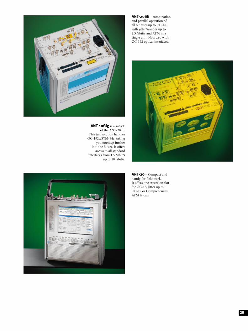
ANT-20SE ± combinationand parallel operation ofall bit rates up to OC-48with jitter/wander up to2.5 Gbit/s and ATM in asingle unit. Now also withOC-192 optical interfaces.
ANT-10Gig is a subsetof the ANT-20SE.
This test solution handlesOC-192c/STM-64c, taking
you one step furtherinto the future. It offers
access to all standardinterfaces from 1.5 Mbit/s
up to 10 Gbit/s.
ANT-20 ± Compact andhandy for field work.It offers one extension slotfor OC-48, Jitter up toOC-12 or ComprehensiveATM testing.
29
Acterna is present in more than 80 countries.To find your local sales office, go to www.acterna.com
Regional Sales Headquarters
Global Headquarters20400 Observation DriveGermantown, Maryland 20876-4023USAToll Free 1-800-638-2049Tel. +1-301-353-1550Fax +1-301-444-8468
www.acterna.com
North America20400 Observation DriveGermantown, Maryland 20876-4023USAToll Free 1-800-638-2049Tel. +1-301-353-1550Fax +1-301-444-8468
Latin AmericaAv. Eng. Luis Carlos Berrini,936-8/9. Andar04571-000 S�o Paulo, SPBrazilTel. +55 11 5503 3800Fax +55 11 5505 1598
Asia/Pacific42 Clarendon StreetPO Box 141South Melbourne, Victoria 3205AustraliaTel. +61 3 9690 6700Fax +61 3 9690 6750
Western EuropeArbachtalstrasse 672800 Eningen u.A.GermanyTel. +49 7121 86 2222Fax +49 7121 86 1222
East Europe, Middle East & AfricaElisabethstrasse 36PO Box 132500 BadenAustriaTel. +43 2252 85521 0Fax +43 2252 80727
1st Neopalimovskiy Per. 15/7 (4th floor)119121 MoscowRussiaTel. +7 095 248 2508Fax +7 095 248 4189
ãC
opyr
ight
20
01
Act
erna
,LLC
.All
righ
tsre
serv
ed.
Sub
ject
toch
ange
wit
hout
noti
ce±
TP/E
N/D
08
5/0
50
1/A
Ere
plD
06
4±
Pri
nted
inG
erm
any
REG.NO 572 - 02


![SDH Pocket Guide - Acterna[1]](https://img.dokumen.tips/doc/110x75/5529110d5503464d2e8b45f8/sdh-pocket-guide-acterna1.jpg)
