Embed Size (px)
Citation preview

4
Advanced Techniques in TEM Specimen Preparation
Jian Li CANMET-Materials Technology Laboratory, Hamilton, Ontario,
Canada
1. Introduction
Since it was invented about 30 years ago, focused ion beam microscopes (FIB) has mostly
been used in semiconductor industry for mask repair, lithography, doping and circuit edit
(Melngailis, 1987). The number of FIB systems increased significantly in recent years, and
their applications have extended into materials and biological sciences (Phaneuf et al.,, 1998,
1999; Li et al., 2001, 2006a).
The recent development of Dual-BeamTM or Cross-BeamTM FIB systems has gradually taken
over the traditional single beam FIB systems. A typical FIB column contains a liquid metal
ion source that produces a finely focused Ga ion beam. The primary Ga ion beam is
accelerated by 30-50 kV, and directed towards the features of interest on the specimen. The
incident ion beam will sputter atoms from the specimen surface, producing both secondary
ions and secondary electrons. Depending on the application, the beam current can be set to
high (e.g. over 60 nA) for rapid ion beam milling. Aside from electron beam imaging,
operator can perform high-resolution ion beam imaging (up to 2.5 nm imaging resolution in
some FIB systems). Site-specific micro-depositions (e.g., Pt, W, C, and SiO2) and micro-
etching can also be achieved by the interaction of the primary ion beam (or electron beam)
with the deposition (or etching) gas introduced into the system. Figure 1 shows a schematic
diagram of ion-specimen interaction in FIB microscopes.
Similar to a typical SEM, FIB microscopes can be used to produce high-resolution images
directly from almost any kind of samples including fine powder particles. The primary Ga
ion beam can produce images with enhanced crystallographic orientation contrast using
secondary electrons (SE) generated from the specimen surface. The ion beam induced
secondary electron yield is strongly dependant on the crystallographic orientation of the
specimen. This is attributed to the very small ion beam-specimen interaction volume. The
secondary ion (SI) particles can also be collected by the detector to produce secondary ion
images that can sometimes provide valuable information related to the local chemistry. In
addition to high-resolution imaging on sample surfaces, ion beam cross sectioning is the
most important feature of FIB microscopes. The stress-free FIB cross-sections produce
valuable subsurface information. In dual-beam FIB systems equipped with EDS and EBSD,
subsurface chemistry and crystallographic orientation of specific subsurface features can be
obtained.
www.intechopen.com

The Transmission Electron Microscope 70
Fig. 1. Schematic diagram of a typical FIB system
Another major application of modern FIB microscopes is to prepare TEM specimens. FIB-TEM specimen preparation techniques have been reported (Giannuzzi & Steve, 1999; Anderson, 2002; Shankar et al., 2003). In this chapter, we will briefly review and compare the currently available techniques, and provide examples using our practical experiences.
2. Focused-ion beam techniques and associated TEM specimen preparation routines
Modern FIB systems are used to perform the following functions: high-resolution imaging
using electron- and ion-beam, TEM specimen preparation (where STEM imaging can be
performed in-situ), micro-machining, micro-deposition, and microanalysis using EDS and
EBSD. Most of FIB microscopes are mainly used to prepare TEM specimens using semi-
automatic routines provided by microscope vendors, while the unique imaging capability
using the primary Ga ion beam has frequently been overlooked. In addition, the high-
resolution SEM column tends to take over the “imaging job” while the Ga ion beam in the
FIB columns are often regarded as the dedicated “milling machine”. Although the modern
FEG SEM columns could, no doubt, achieve higher ultimate imaging resolution, the unique
FIB images are still beneficial in many aspects (Li et al., 2004, 2006a). The heavy Ga ions,
although accelerated by 30 kV, can only penetrate a few nanometers into the specimen
(depending on the material’s properties). This makes FIB imaging extremely surface
sensitive. Strong crystallographic contrast can be obtainable directly from the
metallographic polished surface.
www.intechopen.com
Advanced Techniques in TEM Specimen Preparation 71
2.1 FIB imaging and cross sectioning
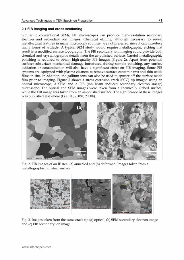
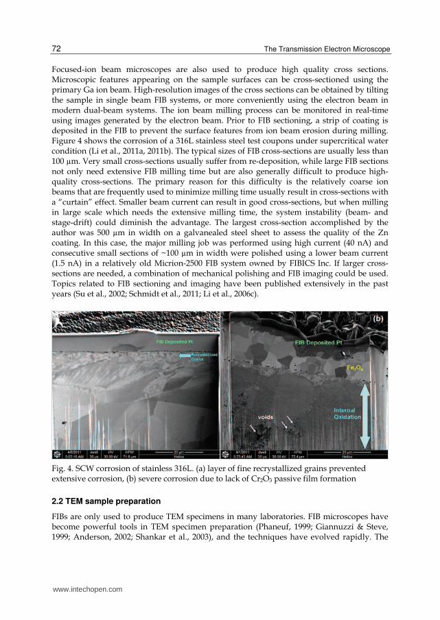
Similar to conventional SEMs, FIB microscopes can produce high-resolution secondary electron and secondary ion images. Chemical etching, although necessary to reveal metallurgical features in many microscopy routines, are not preferred since it can introduce many forms of artifacts. A typical SEM study would require metallographic etching that result in a modified surface topography. The FIB secondary ion imaging could provide both chemical and crystallographic details from the as-polished surface. Careful metallographic polishing is required to obtain high-quality FIB images (Figure 2). Apart from potential surface/subsurface mechanical damage introduced during sample polishing, any surface oxidation or contamination will also have a significant effect on FIB imaging. Some FIB systems are equipped with plasma cleaners to remove surface contaminants and thin oxide films in-situ. In addition, the gallium ions can also be used to sputter off the surface oxide film prior to imaging. Figure 3 shows a stress corrosion crack (SCC) tip imaged using an optical microscope, a SEM and a FIB (ion beam induced secondary electron image) microscope. The optical and SEM images were taken from a chemically etched surface, while the FIB image was taken from an as-polished surface. The significance of these images was published elsewhere (Li et al., 2008a, 2008b).
Fig. 2. FIB images of an IF steel (a) annealed and (b) deformed. Images taken from a metallographic polished surface
Fig. 3. Images taken from the same crack tip (a) optical, (b) SEM secondary electron image and (c) FIB secondary ion image
www.intechopen.com
The Transmission Electron Microscope 72
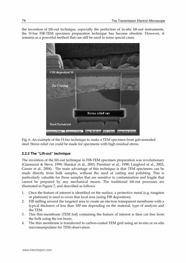
Focused-ion beam microscopes are also used to produce high quality cross sections. Microscopic features appearing on the sample surfaces can be cross-sectioned using the primary Ga ion beam. High-resolution images of the cross sections can be obtained by tilting the sample in single beam FIB systems, or more conveniently using the electron beam in modern dual-beam systems. The ion beam milling process can be monitored in real-time using images generated by the electron beam. Prior to FIB sectioning, a strip of coating is deposited in the FIB to prevent the surface features from ion beam erosion during milling. Figure 4 shows the corrosion of a 316L stainless steel test coupons under supercritical water condition (Li et al., 2011a, 2011b). The typical sizes of FIB cross-sections are usually less than 100 µm. Very small cross-sections usually suffer from re-deposition, while large FIB sections not only need extensive FIB milling time but are also generally difficult to produce high-quality cross-sections. The primary reason for this difficulty is the relatively coarse ion beams that are frequently used to minimize milling time usually result in cross-sections with a “curtain” effect. Smaller beam current can result in good cross-sections, but when milling in large scale which needs the extensive milling time, the system instability (beam- and stage-drift) could diminish the advantage. The largest cross-section accomplished by the author was 500 µm in width on a galvanealed steel sheet to assess the quality of the Zn coating. In this case, the major milling job was performed using high current (40 nA) and consecutive small sections of ~100 µm in width were polished using a lower beam current (1.5 nA) in a relatively old Micrion-2500 FIB system owned by FIBICS Inc. If larger cross-sections are needed, a combination of mechanical polishing and FIB imaging could be used. Topics related to FIB sectioning and imaging have been published extensively in the past years (Su et al., 2002; Schmidt et al., 2011; Li et al., 2006c).
Fig. 4. SCW corrosion of stainless 316L. (a) layer of fine recrystallized grains prevented extensive corrosion, (b) severe corrosion due to lack of Cr2O3 passive film formation
2.2 TEM sample preparation
FIBs are only used to produce TEM specimens in many laboratories. FIB microscopes have become powerful tools in TEM specimen preparation (Phaneuf, 1999; Giannuzzi & Steve, 1999; Anderson, 2002; Shankar et al., 2003), and the techniques have evolved rapidly. The
www.intechopen.com

Advanced Techniques in TEM Specimen Preparation 73
“lift-out” technique has shown significant advantages over the “original” H-bar technique that TEM specimens can be made directly from a bulk specimen (Giannuzzi and Steve, 1999). The original lift-out technique does not allow foil re-thinning once prepared. The lift-out technique was later improved that much thicker specimens (typically 5 µm in thickness) are lifted out from the bulk and then transferred to TEM grids using a micromanipulator (in-situ or ex-situ) followed by final FIB thinning. This technique can be used to produce almost all types of TEM specimens. However they are ineffective in some special cases. In this section, FIB TEM specimen preparation techniques are reviewed and compared using practical examples in our recent research.
2.2.1 Conventional H-bar technique
The conventional H-bar technique was the only available FIB TEM preparation method in
the mid-1990s (Longo et al., 1999). Figure 5 shows a schematic diagram of the H-bar
technique, which includes the following steps:
1. Small samples, containing the feature of interest, (about 2.5x1.0x0.5 mm in size) are cut
out from bulk specimens using a precision diamond cut-off wheel.
2. Both sides of the small specimen are then carefully polished using a “tripod polisher”
(Anderson et al., 1997) in order to produce parallel surfaces and minimize the
mechanical damage introduced during diamond saw cutting. The polished sample
should have a thickness of less than 100 µm.
3. The specimens are then mounted onto a half TEM grid using epoxy adhesive and
allowed sufficient time to cure.
4. The mounted specimens are loaded into a FIB microscope for precise ion-beam
thinning.
Fig. 5. Schematic diagram of conventional FIB-TEM specimen preparation technique
Some thought should be given as to the sample’s thickness before FIB thinning. The thinner the sample, the less the FIB milling time will be needed. However, if the sample is too thin, it may have insufficient mechanical strength, and residual mechanical damage from the mechanical polishing could lead to problems and artifacts. This technique has found many applications, especially for non-site-specific TEM specimens. Once the sample is mounted onto a TEM grid, FIB sectioning and imaging can be used to identify the area of interest, as shown in Figure 6. An electron-transparent TEM sample can subsequently be made by thinning the backside of the specimen. Care must be taken during diamond saw cutting and various stages of mechanical polishing to ensure the integrity of the area of interest. With
www.intechopen.com
The Transmission Electron Microscope 74
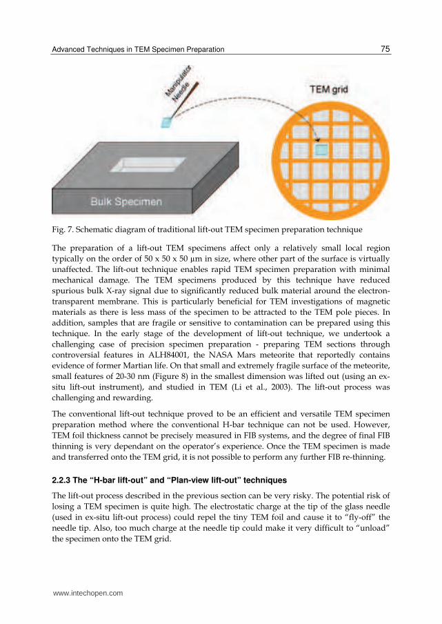
the invention of lift-out technique, especially the perfection of in-situ lift-out instruments, the H-bar FIB-TEM specimen preparation technique has become obsolete. However, it remains as a powerful method that can still be used in some special cases.
Fig. 6. An example of the H-bar technique to make a TEM specimen from galvannealed steel. Stress relief cut could be made for specimens with high residual stress.
2.2.2 The “Lift-out” technique
The invention of the lift-out technique in FIB-TEM specimen preparation was revolutionary (Giannuzzi & Steve, 1999; Shankar et al., 2003; Prenitzer et al., 1998; Langford et al., 2002; Gasser et al., 2004). The main advantage of this technique is that TEM specimens can be made directly from bulk samples, without the need of cutting and polishing. This is particularly valuable for those samples that are sensitive to contamination and fragile that cannot be prepared by any mechanical means. The traditional lift-out processes are illustrated in Figure 7, and described as follows:
1. Once the feature of interest is identified on the surface, a protective metal (e.g. tungsten or platinum) is used to cover that local area (using FIB deposition).
2. FIB milling around the targeted area to create an electron transparent membrane with a typical thickness of less than 100 nm depending on the material, type of analysis and the TEM.
3. This thin-membrane (TEM foil) containing the feature of interest is then cut free from the bulk using the ion beam.
4. The thin membrane is transferred to carbon-coated TEM grid using an in-situ or ex-situ micromanipulator for TEM observation.
www.intechopen.com
Advanced Techniques in TEM Specimen Preparation 75
Fig. 7. Schematic diagram of traditional lift-out TEM specimen preparation technique
The preparation of a lift-out TEM specimens affect only a relatively small local region
typically on the order of 50 x 50 x 50 µm in size, where other part of the surface is virtually
unaffected. The lift-out technique enables rapid TEM specimen preparation with minimal
mechanical damage. The TEM specimens produced by this technique have reduced
spurious bulk X-ray signal due to significantly reduced bulk material around the electron-
transparent membrane. This is particularly beneficial for TEM investigations of magnetic
materials as there is less mass of the specimen to be attracted to the TEM pole pieces. In
addition, samples that are fragile or sensitive to contamination can be prepared using this
technique. In the early stage of the development of lift-out technique, we undertook a
challenging case of precision specimen preparation - preparing TEM sections through
controversial features in ALH84001, the NASA Mars meteorite that reportedly contains
evidence of former Martian life. On that small and extremely fragile surface of the meteorite,
small features of 20-30 nm (Figure 8) in the smallest dimension was lifted out (using an ex-
situ lift-out instrument), and studied in TEM (Li et al., 2003). The lift-out process was
challenging and rewarding.
The conventional lift-out technique proved to be an efficient and versatile TEM specimen
preparation method where the conventional H-bar technique can not be used. However,
TEM foil thickness cannot be precisely measured in FIB systems, and the degree of final FIB
thinning is very dependant on the operator’s experience. Once the TEM specimen is made
and transferred onto the TEM grid, it is not possible to perform any further FIB re-thinning.
2.2.3 The “H-bar lift-out” and “Plan-view lift-out” techniques
The lift-out process described in the previous section can be very risky. The potential risk of
losing a TEM specimen is quite high. The electrostatic charge at the tip of the glass needle
(used in ex-situ lift-out process) could repel the tiny TEM foil and cause it to “fly-off” the
needle tip. Also, too much charge at the needle tip could make it very difficult to “unload”
the specimen onto the TEM grid.
www.intechopen.com

The Transmission Electron Microscope 76
Patterson combined the “H-bar” and “lift-out” techniques (Patterson et.al., 2002). Using this combined method, a much thicker “slab” on the order of ~5 µm in thickness is transferred to a TEM grid (similar to that shown in Figure 7) before final FIB thinning to electron transparency. This is by far the most versatile and widely used lift-out technique under almost all circumstances. Figure 9 shows a relatively thick specimen cut out from a Mg alloy particle to be lifted out for final FIB thinning.
Fig. 8. High-resolution SEM image showing the small feature of interest found on a piece of Martians meteorite, from which a TEM specimen was made.
Fig. 9. H-bar lift out TEM sample preparation from a fine Mg alloy particle.
The H-bar lift-out technique is particularly powerful when used to prepare plan-view TEM specimens. In some TEM investigations, plan-view samples are desired to characterize areas of interest. For example, a TEM foil containing the crack tip would be extremely valuable to understand the mechanism of SCC (Li et al. (2004, 2005, 2006d; Elboujdaini et al. 2004). Preparing site-specific plan-view TEM samples are tedious and time consuming. Figure 10 shows a baddeleyite (ZrO2) grain identified on a small piece of Martian meteorite, which is to be used to date the mineral. The largest challenge posed by baddeleyite in Martian
www.intechopen.com

Advanced Techniques in TEM Specimen Preparation 77
meteorites is their concentration and grain size, with grains typically < 1 to 30 microns in longest dimension. The identified baddeleyite island was lifted out (planview), and fully characterized in TEM (Li et al., 2010; Herd et al. 2010).
2.2.4 The “Direct Lift-out” technique for ultra-fine specimens
The commonly used FIB-TEM specimen preparation techniques present difficulties when dealing with small and delicate samples, such as fine powders and fine and/or fragile fibers. Once the sample dimensions approach the size of the usual lift-out specimen, the application of conventional lift-out techniques becomes difficult. Early work by Cairney and Munroe (Cairney & Munroe, 2001) prepared TEM specimens from fine FeAl and WC powders by embedding the powder into Epoxy resin. A TEM specimen was prepared using the conventional H-bar technique by treating the hardened resin (embedded with the powder particles) as a bulk specimen. TEM specimens prepared using this method contains significant amount of epoxy, and can be problematic in many ways during TEM examination. In addition, residual stress introduced to the particles during the resin-curing process could be unfavorable.
Fig. 10. Planview lift out of a baddeleyite phase from a polished section of Martian meteorite. (a). baddeleyite phase identified on the polished thin section, (b) FIB deposited W to protect the baddeleyite phase from ion beam damaging, (c) The protected zone containing the baddeleyite phase cut free, lifted out and mounted on TEM grid, (d) FIB thinning specimen showing the retained baddeleyite phase.
www.intechopen.com

The Transmission Electron Microscope 78
In a recent study (Li et al. 2003, 2006b), the author needs to evaluate the coating integrity of nickel-coated carbon fibers (about 10 µm in diameter). The entire cross-section of the fiber was to be made electron transparent. The project was to investigate the coating integrity produced using various coating processes. Some of the coatings were extremely fragile or even flaky. The “resin embedding” technique described in the previous section could have caused unacceptable mechanical damage in resin solidification process. None of the lift-out techniques described in the previous section was deemed likely to provide artifact-free TEM samples from these coated fibers. Even the very versatile technique of diamond-knife ultramicrotomy, normally excellent for cross-sectional TEM specimens, would have produced mechanically damaged or “shattered” cross-sections, and coating delamination would have been highly likely. The authored discovered the fine glass needle used for ex-situ lift-out process can pick up much larger pieces than previously reported (Li et al., 2006b). The fibers were first carefully cut to 4-5 mm in length and transferred onto the inner edge of a TEM copper grid using an ex-situ micromanipulator. A minimal amount of low-shrinkage epoxy was used to stabilize the fiber to the grid. The fiber that is fixed onto the grid was then directly cut and thinned in a FIB microscope. Figure 11 shows the FIB and
Fig. 11. FIB and TEM images of successfully prepared TEM specimens using the direct lift-out technique. (a) FIB low magnification image of a bundle of fine fibers. (b) FIB image of a mounted fiber on a copper grid. (c) A low-magnification TEM image of a fiber with good coating quality. (d) Low-magnification TEM image showing a fiber with poor coating quality.
www.intechopen.com
Advanced Techniques in TEM Specimen Preparation 79
TEM images of the fiber made using the direct lift-out technique. There are several advantages of this new technique:
1. The entire cross-section of the fiber can be made electron transparent for TEM observation.
2. Minimum mechanical damage is introduced during the TEM specimen preparation process.
3. Lower risk of mechanical damage by the micromanipulator compared to other lift-out processes.
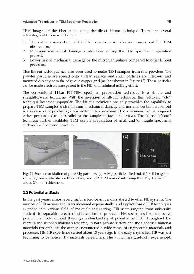
This lift-out technique has also been used to make TEM samples from fine powders. The
powder particles are spread onto a clean surface, and small particles are lifted-out and
mounted directly onto the edge of a copper grid (as that shown in Figure 12). These particles
can be made electron transparent in the FIB with minimal milling effort.
The conventional H-bar FIB-TEM specimen preparation technique is a simple and
straightforward technique. With the invention of lift-out technique, this relatively “old”
technique becomes unpopular. The lift-out technique not only provides the capability to
prepare TEM samples with minimum mechanical damage and minimal contamination, but
is also capable of producing site-specific TEM specimens. TEM specimens can be prepared
either perpendicular or parallel to the sample surface (plan-view). The “direct lift-out”
technique further facilitates TEM sample preparation of small and/or fragile specimens
such as fine fibers and powders.
Fig. 12. Surface oxidation of pure Mg particles, (a) A Mg particle lifted out, (b) FIB image of showing thin oxide film on the surface, and (c) STEM work confirming thin MgO layer of about 20 nm in thickness.
2.3 Potential artifacts
In the past years, almost every major micro-beam vendors started to offer FIB systems. The
number of FIB owners and users increased exponentially, and applications of FIB techniques
extended into various field of materials engineering. FIB users ranging from university
students to reputable research institutes start to produce TEM specimens like in massive
production mode without thorough understanding of potential artifact. Throughout the
years in the author’s materials research, in both private sectors and the Canadian national
materials research lab, the author encountered a wide range of engineering materials and
processes. His FIB experience started about 15 years ago in the early days when FIB was just
beginning to be noticed by materials researchers. The author has gradually experienced,
www.intechopen.com
The Transmission Electron Microscope 80
learned, and start to understand and tried hard to cope with most of the commonly
occurring FIB-induced artifacts, and in many cases, after hard lessons learnt.
Common FIB induced artifacts include:
1. “curtain effect”: due to insufficient FIB metal deposition and improper milling parameter.
2. low melting point gallium phase formation on sample surface, 3. beam damage on FIB prepared TEM specimens, 4. beam induced grain growth in nano-crystalline materials, 5. beam damage to most of the HCP materials, 6. materials redeposition during milling, 7. surface amphorization.
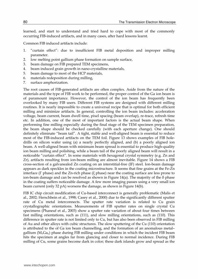
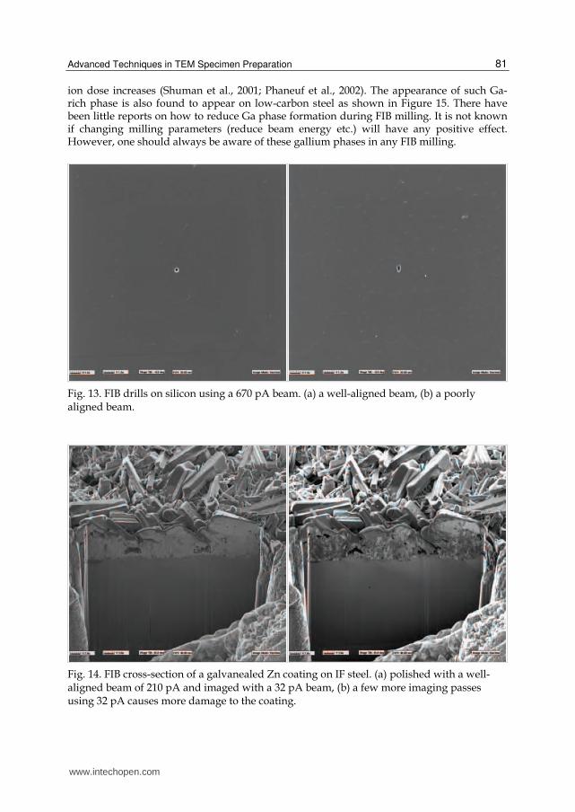
The root causes of FIB-generated artifacts are often complex. Aside from the nature of the materials and the type of FIB work to be performed, the proper control of the Ga ion beam is of paramount importance. However, the control of the ion beam has frequently been overlooked by many FIB users. Different FIB systems are designed with different milling routines. It is nearly impossible to create a universal recipe that is optimal for both efficient milling and minimize artifacts. In general, controlling the ion beam includes: acceleration voltage, beam current, beam dwell time, pixel spacing (beam overlap), re-trace, refresh time etc. In addition, one of the most of important factors is the actual beam shape. When performing fine milling especially during the final stage of the TEM specimen preparation, the beam shape should be checked carefully (with each aperture change). One should definitely eliminate “beam tail”. A tight, stable and well-aligned beam is essential to reduce most of the FIB-induced artifacts on the TEM foil. Figure 13 shows examples of FIB hole-drills on silicon wafer using (a) a nearly perfectly aligned, and (b) a poorly aligned ion beam. A well-aligned beam with minimum beam spread is essential to produce high-quality ion beam milling and polishing, while a beam tail of the poorly aligned beam will result in a noticeable “curtain effect”. In some materials with hexagonal crystal symmetry (e.g. Zn and Zr), artifacts resulting from ion-beam milling are almost inevitable. Figure 14 shows a FIB cross-section of a galvanealed Zn coating on an interstitial-free (IF) steel. Ion-beam damage appears as dark speckles in the coating microstructure. It seems that fine grains at the Fe-Zn interface (Г phase) and the Zn-rich phase (ξ phase) near the coating surface are less prone to ion-beam damage and can be resolved as shown in Figure 14(a). The majority of the δ phase in the coating suffers noticeable damage. A few more imaging passes using a very small ion beam current (only 32 pA) worsens the damage, as shown in Figure 14(b).
FIB IC chip circuit modification of Cu-based interconnect is generally problematic (Malis et al., 2002; Herschbein et al., 1998; Casey et al., 2000) due to the significantly different sputter rate of Cu metal interconnects. The sputter rate variation is related to Cu grain crystallographic orientations. Measurements of FIB sputter rates on single crystal Cu specimens (Phaneuf et al., 2003) show a sputter rate variation of about four times between fast milling orientations, such as (111), and slow milling orientations, such as (110). This difference in sputter rate is not limited only to Cu, but has also been observed in FIB milling of Au and other alloys with cubic structures. The slow sputtering of the Cu (110) orientation is attributed to the of Ga ion beam channelling, and the formation of an anomalous metal–gallium (MxGay) phase during FIB milling under conditions in which the incident FIB beam hits the specimen at angles far from glancing and closer to normal incidence. During FIB milling of Cu, some grains become dark in color; these dark islands grow and spread as the
www.intechopen.com
Advanced Techniques in TEM Specimen Preparation 81
ion dose increases (Shuman et al., 2001; Phaneuf et al., 2002). The appearance of such Ga-rich phase is also found to appear on low-carbon steel as shown in Figure 15. There have been little reports on how to reduce Ga phase formation during FIB milling. It is not known if changing milling parameters (reduce beam energy etc.) will have any positive effect. However, one should always be aware of these gallium phases in any FIB milling.
Fig. 13. FIB drills on silicon using a 670 pA beam. (a) a well-aligned beam, (b) a poorly aligned beam.
Fig. 14. FIB cross-section of a galvanealed Zn coating on IF steel. (a) polished with a well-aligned beam of 210 pA and imaged with a 32 pA beam, (b) a few more imaging passes using 32 pA causes more damage to the coating.
www.intechopen.com

The Transmission Electron Microscope 82
Fig. 15. FexGay phase formation on low carbon steel during FIB imaging. (a) first image pass, (b) multiple imaging passes under 1.5 nA beam current, (c) multiple passes under 6 nA beam.
3. Conclusion
Advances in materials engineering depend heavily on high-level microstructure characterization using a combination of state-of-the-art instruments. New characterization techniques and methodologies are critical in understanding the fundamentals of materials properties. High-quality TEM work is heavily dependent on the preparation of TEM foil with minimum artifacts. FIB lift-out techniques are versatile, and can produce almost any kind of TEM specimen (provided they are both vacuum and beam stable). The operator should always try to optimize milling parameters in order to reduce potential artifacts.
4. Acknowledgement
The author gratefully acknowledges the efforts of the following individuals for their contributions of research and consultations leading to the completion of this book chapter: Tom malis, Pei Liu, Catherine Bibby, Wenyue Zheng and Darren Bibby (Materials Technology Laboratory, Natural Resources Canada), Michael Phaneuf (Fibics Incorporated), Chris Herd (University of Alberta) and George Kiporous (Dalhousie University).
5. References
Anderson, R. (2002). Comparison of FIB TEM Specimen Preparation Methods, Proceeding of Microscopy and Microanalysis, 2002, vol.8, pp. 44-45.
Anderson, R. & Klepeis, S.J. (1997). Combined Tripod Polishing and FIB Method for Preparing Semiconductor Plan View Specimens, Materials Research Society Symposium Proceedings, Pittsburgh, 1997, vol. 480, p. 187.
Cairney, J.M. & Munroe, P.R. (2001). Preparation of transmission electron microscope specimens from FeAl and WC powders using focused-ion beam milling, Materials Characterization, 2001, 46, pp. 297-304.
Casey, J.D., Noll, K.E., Shuman, R., Chandler, C., Megordan, M., Phaneuf, M. and Li, J (2000). Copper Device Editing Strategy for FIB Milling, LSI Testing Symposium, 2000, Osaka, Japan.
www.intechopen.com
Advanced Techniques in TEM Specimen Preparation 83
Gasser, P., Klotz, U.E., Khalid, F.A. and Beffort, O. (2004). Site-specific specimen preparation by focused ion beam milling for transmission electron microscopy of metal-matrix composites. Microscopy and Microanalysis, 2004, vol.10, pp. 311-316.
Giannuzzi, L.A. and Stevie, F.A. (1999). A review of focused ion beam milling techniques for TEM specimen preparation, Micron, 1999, vol. 30, pp. 197-204.
Elboujdaini, M., Li, J., Gertsman, V., Gu, G., Revie, W., Gao, M. and Katz, D. (2004). NACE International Conference, CORROSION, 2004, March, Paper#04554; New Orleans.
C.D.K.Herd, R.A.Stern, E.L.Walton, Li,J. and Bibby, C. (2010). TEM and SEM-CL Analysis of the Baddeleyite in NWA 3171: Geochronological Implications for Martian Meteorites, Lunar and Planetary Science Conference XLI, Paper#2280, March 1-5, 2010, Houston, Texes.
Herschbein, S., Fisher, L.S., Kane, T.L., Tenney, M.P. and Shore, A.D. (1998). Focus Ion Beam Process for Removal of Copper, Proc. ISTFA, 1998, p. 127.
Langford, R.M., Petford-Long, A.K. and Gnauck, P. (2002). Preparation of Transmission Electron Microscopy Cross-section Specimens Using Focused ion Beam Milling, Journal of Cacuum Science and Technology A, 2001, vol. 9, pp. 2186-2193.
Li, J., McMahon, G.S. and Phaneuf, M.W. (2001). Proceedings of the Microscopically Society of Canada, 2001, vol. XXVIII, pp. 26-27.
Li, J., Gertsman, V.Y. and Lo, J. (2003). Preparation of Transmission Electron Microscope Specimens from Ultra-fine Fibers by a FIB Technique, Microscopy and Microanalysis, 2003, vol.9 (2), pp. 888-889.
Li, J., Elboujdaini, M. and Gertsman, V.Y., Gao, M. and Katz, D.C. (2004). Advanced characterization of a stress corrosion crack from an in-field serviced X-52 steel line pipe, In: Aerospace Materials and Manufacturing: Development, Testing and Life Cycle Issues, ed. P.C. patnaik, 2004, pp. 515-523.
Li, Jian, Elboujdaini, M., Gertsman, V. Y., Gao, M. and Katz, D. C. (2005), Characterization of a Stress Corrosion Crack with FIB and TEM, Canadian Metallurgical Quarterly, 2005, vol.44 (3), pp. 331-338.
Li, J. (2006a). Focused Ion Beam Microscope – More than a Precision Ion Milling Machine, Journal of Metal, 2006, vol.58 no.3, pp. 27-31.
Li, J., Dionne, S. and Malis T. (2006b). Recent Advances in FIB-TEM Specimen Preparation Techniques,Materials Characterization, 2006, vol. 57, pp. 64-70.
Li, J., Elboujdaini, M. and Liu, P. (2006c). Crack Tip Plastic Zone Formation during Pipeline Hydrostatic Testing,Proceeding of Microscopy and Microanalysis 2006, Chicago, August, 2006, vol.12, pp. 1306-1307.
Li, J., Elboujdaini, M., Fang, B., Revie, R.W. and Phaneuf, M.W. (2006d). Microscopy Study of Intergranular Stress Corrosion Cracking of X-52 Line Pipe Steel, Corrosion, 2006, vol. 62 (4), pp. 316-322.
Li, J., Elboujdaini, M., Gao, M. and Revie, R.W. (2008a). Formation of Plastic Zone at the SCC Tip in a Pipeline Experienced Hydrostatic Testing, Materials Science and Engineering A, 2008, vol. 486, pp. 496–502.
Li, J. (2008b). The Detection of Local Plastic Strain in Microscopic Scale, Materials Letters, 2008, vol. 62, issu.6-7, pp. 804-807.
Li, J., Herd, C. & Malis, T. (2010). Investigation of Baddeleyite Phase Found in Martian Meteorites, Microsc. Microanal. 2010, vol. 16 (Suppl 2), pp. 218-219.
www.intechopen.com

The Transmission Electron Microscope 84
Li, J., Zheng, W., Cook, W., Toivonen, A., Penttilä, S., Guzonas, D., Woo, O.T., Liu, P., and Bibby, D. (2011a). Effect of Coating and Surface Modification on the Corrosion Resistance of Selected Alloys in Supercritical Water, 32nd Annual CNS Conference, Niagara Falls, ON, June 5-8, 2011.
Li, J., Zheng, W., Kuyucak, S., Miles, J., Cook, W., Woo, O.T., Zhou, Z. & Ge, C. (2011b). Corrosion Resistance of Experimental Alloys and Coatings Under SCW Conditions, 5th International Conference on SCWR (ISSCWR-5), Vancouver, BC, March 13-16, 2011.
Longo, D.M., Howe and Johnson, W. C., Experimental method for determining Cliff–Lorimer factors in transmission electron microscopy (TEM) utilizing stepped wedge-shaped specimens prepared by focused ion beam (FIB) thinning, Ultramicroscopy, 1999, vol. 80, (2), pp. 69-84.
Malis,T., Carpenter, G.J.C., Dionne, S., Botton, G.A. and Phaneuf, M.W. (2002). Industrial Applications of Electron Microscopy, ed. Li, Zhigang R., Marcel Dekker Inc. New York, 2002.
Melngailis, J. J. (1987). Focused ion beam technology and applications, Vac. Sci. Technol. B, 1987, vol. 5(2), pp. 469-495.
Patterson, R.J., Mayer, D., Weaver, L. and Phaneuf, M.W. (2002). FIB-TEM Preparation for Ex- Situ Cross- Sectional and Plan-View FIB Specimen Preparation, Proceeding of Microscopy and Microanalysis, 2002, vol.8, pp. 566-567.
Phaneuf, M. W.; Li, Jian and Malis, T. (1998). FIB techniques for analysis of metallurgical specimens, Microscopy and Microanalysis, 1998, vol. 4, pp. 492-493.
Phaneuf, M. W. (1999). Imaging, spectroscopy and spectroscopic imaging with an energy- filtered field emission TEM, Micron, 1999, vol. 30, pp. 277-288.
Phaneuf, M.W., Li, J. & Casey, J.D. Jr. (2002). Gallium Phase Formation in Cu and Other FCC Metals During Near-Normal Incidence Ga-FIB Milling and Techniques to Avoid this Phenomenon, Microscopy and Microanalysis. 2002, vol. 8 (2), pp. 52-53.
Phaneuf, M.W., Li, J., Shuman, R.F. Noll, K. and Casey, J.D. Jr. (2003). Apparatus and method for reducing differential sputter rates, US patent #6,641,705, issued November 04, 2003.
Prenitzer, B.I., Giannuzzi, L.A., Newman, K., Brown, S.R., Irwin, R.B., Shofner, T.L. and Stevie, F.A. (1998). Transmission Electron Microscope Specimen Preparation of Zn Powders Using the Focused Ion Beam Lift-out Technique, Metallurgical and Materials Transactions A, 1998, vol. 29A, pp. 2399-2406.
Schmidt, F., Uhbacher, M., Kyriakopoulos, A. , Schubert, H. & Zehbe, R. (2011). From 2D slices to 3D volumes: Image based reconstruction and morphological characterization of hippocampal cells on charged and uncharged surfaces using FIB/SEM serial sectioning, Ultramicroscopy, (111), 2011, pp. 259-266.
Shankar, S. Riddle, Y.W. & Makhlouf, M.M. (2003). Focused ion beam milling: A practical method for preparing cast Al-Si alloy samples for transmission electron microscopy, Metallurgical and Materials Transactions A, 2003, vol. 34A, pp. 705-707.
Shuman, R.F., Noll, K., Casey, J.D. Jr. (2001). Copper Device Editing: Strategy for Focused Ion Beam Milling of Copper, U.S. Patent 6,322,672 B1, issued November 2001.
Su, X., Bouchard, R., Li, J. & Tyson, W.R. (2002). Identification of Cleavage Origins Using Focused Ion Beam (FIB) Sectioning, Microsco. Microanal. 2002, 8 (Suppl. 2) , p548.
www.intechopen.com

The Transmission Electron MicroscopeEdited by Dr. Khan Maaz
ISBN 978-953-51-0450-6Hard cover, 392 pagesPublisher InTechPublished online 04, April, 2012Published in print edition April, 2012
InTech EuropeUniversity Campus STeP Ri Slavka Krautzeka 83/A 51000 Rijeka, Croatia Phone: +385 (51) 770 447 Fax: +385 (51) 686 166www.intechopen.com
InTech ChinaUnit 405, Office Block, Hotel Equatorial Shanghai No.65, Yan An Road (West), Shanghai, 200040, China
Phone: +86-21-62489820 Fax: +86-21-62489821
The book "The Transmission Electron Microscope" contains a collection of research articles submitted byengineers and scientists to present an overview of different aspects of TEM from the basic mechanisms anddiagnosis to the latest advancements in the field. The book presents descriptions of electron microscopy,models for improved sample sizing and handling, new methods of image projection, and experimentalmethodologies for nanomaterials studies. The selection of chapters focuses on transmission electronmicroscopy used in material characterization, with special emphasis on both the theoretical and experimentalaspect of modern electron microscopy techniques. I believe that a broad range of readers, such as students,scientists and engineers will benefit from this book.
How to referenceIn order to correctly reference this scholarly work, feel free to copy and paste the following:
Jian Li (2012). Advanced Techniques in TEM Specimen Preparation, The Transmission Electron Microscope,Dr. Khan Maaz (Ed.), ISBN: 978-953-51-0450-6, InTech, Available from:http://www.intechopen.com/books/the-transmission-electron-microscope/advanced-techniques-in-tem-specimen-preparation

© 2012 The Author(s). Licensee IntechOpen. This is an open access articledistributed under the terms of the Creative Commons Attribution 3.0License, which permits unrestricted use, distribution, and reproduction inany medium, provided the original work is properly cited.