Embed Size (px)
Citation preview
AMVS
Advanced MPLSVPN SolutionsVolume 1Version 1.0
Student GuideText Part Number: 97-0624-01
The products and specifications, configurations, and other technical information regarding the products in thismanual are subject to change without notice. All statements, technical information, and recommendations in thismanual are believed to be accurate but are presented without warranty of any kind, express or implied. Youmust take full responsibility for their application of any products specified in this manual.LICENSEPLEASE READ THESE TERMS AND CONDITIONS CAREFULLY BEFORE USING THE MANUAL,DOCUMENTATION, AND/OR SOFTWARE (“MATERIALS”). BY USING THE MATERIALS YOUAGREE TO BE BOUND BY THE TERMS AND CONDITIONS OF THIS LICENSE. IF YOU DO NOTAGREE WITH THE TERMS OF THIS LICENSE, PROMPTLY RETURN THE UNUSED MATERIALS(WITH PROOF OF PAYMENT) TO THE PLACE OF PURCHASE FOR A FULL REFUND.Cisco Systems, Inc. (“Cisco”) and its suppliers grant to you (“You”) a nonexclusive and nontransferable licenseto use the Cisco Materials solely for Your own personal use. If the Materials include Cisco software(“Software”), Cisco grants to You a nonexclusive and nontransferable license to use the Software in object codeform solely on a single central processing unit owned or leased by You or otherwise embedded in equipmentprovided by Cisco. You may make one (1) archival copy of the Software provided You affix to such copy allcopyright, confidentiality, and proprietary notices that appear on the original. EXCEPT AS EXPRESSLYAUTHORIZED ABOVE, YOU SHALL NOT: COPY, IN WHOLE OR IN PART, MATERIALS; MODIFYTHE SOFTWARE; REVERSE COMPILE OR REVERSE ASSEMBLE ALL OR ANY PORTION OF THESOFTWARE; OR RENT, LEASE, DISTRIBUTE, SELL, OR CREATE DERIVATIVE WORKS OF THEMATERIALS.You agree that aspects of the licensed Materials, including the specific design and structure of individualprograms, constitute trade secrets and/or copyrighted material of Cisco. You agree not to disclose, provide, orotherwise make available such trade secrets or copyrighted material in any form to any third party without theprior written consent of Cisco. You agree to implement reasonable security measures to protect such tradesecrets and copyrighted Material. Title to the Materials shall remain solely with Cisco.This License is effective until terminated. You may terminate this License at any time by destroying all copiesof the Materials. This License will terminate immediately without notice from Cisco if You fail to comply withany provision of this License. Upon termination, You must destroy all copies of the Materials.Software, including technical data, is subject to U.S. export control laws, including the U.S. ExportAdministration Act and its associated regulations, and may be subject to export or import regulations in othercountries. You agree to comply strictly with all such regulations and acknowledge that it has the responsibilityto obtain licenses to export, re-export, or import Software.This License shall be governed by and construed in accordance with the laws of the State of California, UnitedStates of America, as if performed wholly within the state and without giving effect to the principles of conflictof law. If any portion hereof is found to be void or unenforceable, the remaining provisions of this License shallremain in full force and effect. This License constitutes the entire License between the parties with respect tothe use of the MaterialsRestricted Rights - Cisco’s software is provided to non-DOD agencies with RESTRICTED RIGHTS and itssupporting documentation is provided with LIMITED RIGHTS. Use, duplication, or disclosure by the U.S.Government is subject to the restrictions as set forth in subparagraph “C” of the Commercial ComputerSoftware - Restricted Rights clause at FAR 52.227-19. In the event the sale is to a DOD agency, the U.S.Government’s rights in software, supporting documentation, and technical data are governed by the restrictionsin the Technical Data Commercial Items clause at DFARS 252.227-7015 and DFARS 227.7202.DISCLAIMER OF WARRANTY. ALL MATERIALS ARE PROVIDED “AS IS” WITH ALL FAULTS.CISCO AND ITS SUPPLIERS DISCLAIM ALL WARRANTIES, EXPRESSED OR IMPLIED, INCLUDING,WITHOUT LIMITATION, THOSE OF MERCHANTABILITY, FITNESS FOR A PARTICULAR PURPOSEAND NONINFRINGEMENT OR ARISING FROM A COURSE OF DEALING, USAGE, OR TRADEPRACTICE.IN NO EVENT SHALL CISCO OR ITS SUPPLIERS BE LIABLE FOR ANY INDIRECT, SPECIAL,CONSEQUENTIAL, OR INCIDENTAL DAMAGES, INCLUDING, WITHOUT LIMITATION, LOSTPROFITS OR LOSS OR DAMAGE TO DATA ARISING OUT OF THE USE OR INABILITY TO USE THISMANUAL, EVEN IF CISCO OR ITS SUPPLIERS HAVE BEEN ADVISED OF THE POSSIBILITY OFSUCH DAMAGES. In no event shall Cisco’s or its suppliers’ liability to You, whether in contract, tort(including negligence), or otherwise, exceed the price paid by You. The foregoing limitations shall apply evenif the above-stated warranty fails of its essential purpose.The following information is for FCC compliance of Class A devices: This equipment has been tested andfound to comply with the limits for a Class A digital device, pursuant to part 15 of the FCC rules. These limitsare designed to provide reasonable protection against harmful interference when the equipment is operated in acommercial environment. This equipment generates, uses, and can radiate radio-frequency energy and, if notinstalled and used in accordance with the instruction manual, may cause harmful interference to radiocommunications. Operation of this equipment in a residential area is likely to cause harmful interference, inwhich case users will be required to correct the interference at their own expense.The following information is for FCC compliance of Class B devices: The equipment described in this manualgenerates and may radiate radio-frequency energy. If it is not installed in accordance with Cisco’s installationinstructions, it may cause interference with radio and television reception. This equipment has been tested andfound to comply with the limits for a Class B digital device in accordance with the specifications in part 15 of
the FCC rules. These specifications are designed to provide reasonable protection against such interference in aresidential installation. However, there is no guarantee that interference will not occur in a particularinstallation.You can determine whether your equipment is causing interference by turning it off. If the interference stops, itwas probably caused by the Cisco equipment or one of its peripheral devices. If the equipment causesinterference to radio or television reception, try to correct the interference by using one or more of the followingmeasures:• Turn the television or radio antenna until the interference stops.• Move the equipment to one side or the other of the television or radio.• Move the equipment farther away from the television or radio.• Plug the equipment into an outlet that is on a different circuit from the television or radio. (That is, makecertain the equipment and the television or radio are on circuits controlled by different circuit breakers or fuses.)Modifications to this product not authorized by Cisco Systems, Inc. could void the FCC approval and negateyour authority to operate the product.The following third-party software may be included with your product and will be subject to the softwarelicense agreement:CiscoWorks software and documentation are based in part on HP OpenView under license from the Hewlett-Packard Company. HP OpenView is a trademark of the Hewlett-Packard Company. Copyright © 1992, 1993Hewlett-Packard Company.The Cisco implementation of TCP header compression is an adaptation of a program developed by theUniversity of California, Berkeley (UCB) as part of UCB’s public domain version of the UNIX operatingsystem. All rights reserved. Copyright © 1981, Regents of the University of California.Network Time Protocol (NTP). Copyright © 1992, David L. Mills. The University of Delaware makes norepresentations about the suitability of this software for any purpose.
Point-to-Point Protocol. Copyright © 1989, Carnegie-Mellon University. All rights reserved. The name of theUniversity may not be used to endorse or promote products derived from this software without specific priorwritten permission.
The Cisco implementation of TN3270 is an adaptation of the TN3270, curses, and termcap programs developedby the University of California, Berkeley (UCB) as part of UCB’s public domain version of the UNIX operatingsystem. All rights reserved. Copyright © 1981-1988, Regents of the University of California.
Cisco incorporates Fastmac and TrueView software and the RingRunner chip in some Token Ring products.Fastmac software is licensed to Cisco by Madge Networks Limited, and the RingRunner chip is licensed toCisco by Madge NV. Fastmac, RingRunner, and TrueView are trademarks and in some jurisdictions registeredtrademarks of Madge Networks Limited. Copyright © 1995, Madge Networks Limited. All rights reserved.
XRemote is a trademark of Network Computing Devices, Inc. Copyright © 1989, Network Computing Devices,Inc., Mountain View, California. NCD makes no representations about the suitability of this software for anypurpose.
The X Window System is a trademark of the X Consortium, Cambridge, Massachusetts. All rights reserved.
Access Registrar, AccessPath, Any to Any, Are You Ready, AtmDirector, Browse with Me, CCDA, CCDE,CCDP, CCIE, CCNA, CCNP, CCSI, CD-PAC, the Cisco logo, Cisco Certified Internetwork Expert logo,CiscoLink, the Cisco Management Connection logo, the Cisco NetWorks logo, the Cisco Powered Networklogo, Cisco Systems Capital, the Cisco Systems Capital logo, Cisco Systems Networking Academy, the CiscoSystems Networking Academy logo, the Cisco Technologies logo, Fast Step, FireRunner, Follow Me Browsing,FormShare, GigaStack, IGX, Intelligence in the Optical Core, Internet Quotient, IP/VC, IQ Breakthrough, IQExpertise, IQ FastTrack, IQ Readiness Scorecard, The IQ Logo, Kernel Proxy, MGX, Natural Network Viewer,NetSonar, Network Registrar, the Networkers logo, Packet, PIX, Point and Click Internetworking, PolicyBuilder, Precept, RateMUX, ReyMaster, ReyView, ScriptShare, Secure Script, Shop with Me, SlideCast,SMARTnet, SVX, The Cell, TrafficDirector, TransPath, VlanDirector, Voice LAN, Wavelength Router,Workgroup Director, and Workgroup Stack are trademarks; Changing the Way We Work, Live, Play, andLearn, Empowering the Internet Generation, The Internet Economy, and The New Internet Economy are servicemarks; and Aironet, ASIST, BPX, Catalyst, Cisco, Cisco IOS, the Cisco IOS logo, Cisco Systems, the CiscoSystems logo, the Cisco Systems Cisco Press logo, CollisionFree, Enterprise/Solver, EtherChannel,EtherSwitch, FastHub, FastLink, FastPAD, FastSwitch, GeoTel, IOS, IP/TV, IPX, LightStream, LightSwitch,MICA, NetRanger, Post-Routing, Pre-Routing, Registrar, StrataView Plus, Stratm, TeleRouter, and VCO areregistered trademarks of Cisco Systems, Inc. or its affiliates in the U.S. and certain other countries. All othertrademarks mentioned in this document are the property of their respective owners. The use of the word partnerdoes not imply a partnership relationship between Cisco and any of its resellers. (0005R)
Advanced MPLS VPN Solutions, Revision 1.0: Student GuideCopyright 2000, Cisco Systems, Inc.All rights reserved. Printed in USA.

Copyright 2000, Cisco Systems, Inc. Advanced MPLS VPN Solutions v
Table of Contents
Volume 1
ADVANCED MPLS VPN SOLUTIONS 1-1
Overview 1-1
Course Objectives 1-2Course Objectives – Implementation 1-3Course Objectives – Solutions 1-4
Prerequisites 1-5
Participant Role 1-7
General Administration 1-9
Sources of Information 1-10
MPLS VPN TECHNOLOGY 2-1
Overview 2-1Objectives 2-1
Introduction to Virtual Private Networks 2-2Objectives 2-2Summary 2-8Review Questions 2-8
Overlay and Peer-to-Peer VPN 2-9Objectives 2-9Overlay VPN Implementations 2-13Summary 2-23Review Questions 2-24
Major VPN Topologies 2-25Objectives 2-25VPN Categorizations 2-25Summary 2-38Review Questions 2-38
MPLS VPN Architecture 2-39Objectives 2-39Summary 2-60Review Questions 2-61
MPLS VPN Routing Model 2-62Objectives 2-62Summary 2-78Review Questions 2-78
MPLS VPN Packet Forwarding 2-79Objectives 2-79Summary 2-91Review Questions 2-91Lesson Summary 2-92
Answers to Review Questions 2-93Introduction to Virtual Private Networks 2-93Overlay and Peer-to-Peer VPN 2-93
vi Advanced MPLS VPN Solutions Copyright 2000, Cisco Systems, Inc.
Major VPN Topologies 2-94MPLS VPN Architecture 2-94MPLS VPN Routing Model 2-95MPLS VPN Packet Forwarding 2-96
MPLS/VPN CONFIGURATION ON IOS PLATFORMS 3-1
Overview 3-1Objectives 3-1
MPLS/VPN Mechanisms in Cisco IOS 3-2Objectives 3-2Summary 3-16Review Questions 3-16
Configuring Virtual Routing and Forwarding Table 3-17Objectives 3-17Summary 3-26Review Questions 3-26
Configuring a Multi-Protocol BGP Session Between the PE Routers 3-27Objectives 3-27Summary 3-43Review Questions 3-43
Configuring Routing Protocols Between PE and CE Routers 3-44Objectives 3-44Summary 3-55Review Questions 3-55
Monitoring MPLS/VPN Operation 3-56Objectives 3-56Summary 3-82Review Questions 3-82
Troubleshooting MPLS/VPN 3-83Objectives 3-83Summary 3-100Review Questions 3-100
Advanced VRF Import/Export Features 3-101Objectives 3-101Summary 3-115Review Questions 3-115
Advanced PE-CE BGP Configuration 3-116Objectives 3-116Summary 3-134Review Questions 3-134
USING OSPF IN AN MPLS VPN ENVIRONMENT 4-1
Overview 4-1Objectives 4-1
Using OSPF as the PE-CE Protocol in an MPLS VPN Environment 4-2Objectives 4-2Summary 4-26Review Questions 4-26
Configuring and Monitoring OSPF in an MPLS VPN Environment 4-27Objectives 4-27Summary 4-35Review Questions 4-35
Copyright 2000, Cisco Systems, Inc. Advanced MPLS VPN Solutions vii
Summary 4-36
Answers to Review Questions 4-37Using OSPF as the PE-CE Protocol in an MPLS VPN Environment 4-37Configuring and Monitoring OSPF in an MPLS VPN Environment 4-37
Volume 2
MPLS VPN TOPOLOGIES 5-1
Overview 5-1Objectives 5-1
Simple VPN with Optimal Intra-VPN Routing 5-2Objectives 5-2Summary 5-17Review Questions 5-17
Using BGP as the PE-CE Routing Protocol 5-18Objectives 5-18Summary 5-23Review Questions 5-23
Overlapping Virtual Private Networks 5-24Objectives 5-24Summary 5-33Review Questions 5-33
Central Services VPN Solutions 5-34Objectives 5-34Summary 5-47Review Questions 5-47
Hub-andSpoke VPN Solutions 5-48Objectives 5-48Summary 5-54Review Questions 5-54
Managed CE-Router Service 5-55Objectives 5-55Summary 5-60Review Questions 5-60Chapter Summary 5-60
INTERNET ACCESS FROM A VPN 6-1
Overview 6-1Objectives 6-1
Integrating Internet Access with the MPLS VPN Solution 6-2Objectives 6-2Summary 6-16Review Questions 6-16
Design Options for Integrating Internet Access with MPLS VPN 6-17Objectives 6-17Summary 6-23Review Questions 6-23
Leaking Between VPN and Global Backbone Routing 6-24Objectives 6-24Usability of Packet Leaking for Various Internet Access Services 6-32Redundant Internet Access with Packet Leaking 6-36Summary 6-38Review Questions 6-38
viii Advanced MPLS VPN Solutions Copyright 2000, Cisco Systems, Inc.
Separating Internet Access from VPN Service 6-39Objectives 6-39Usability of Separated Internet Access for Various InternetAccess Services 6-44Summary 6-46Review Questions 6-46
Internet Access Backbone as a Separate VPN 6-47Objectives 6-47Usability of Internet in a VPN Solution for Various InternetAccess Services 6-52Summary 6-56Review Questions 6-57Chapter Summary 6-57
MPLS VPN DESIGN GUIDELINES 7-1
Overview 7-1Objectives 7-1
Backbone and PE-CE Link Addressing Scheme 7-2Objectives 7-2Summary 7-15Review Questions 7-16
Backbone IGP Selection and Design 7-17Objectives 7-17Summary 7-30Review Questions 7-31
Route Distinguisher and Route Target Allocation Schemes 7-32Objective 7-32Summary 7-37Review Questions 7-37
End-to-End Convergence Issues 7-38Objectives 7-38Summary 7-52Review Questions 7-52Chapter Summary 7-53
Answers to Review Questions 7-54Backbone and PE-CE Link Addressing Scheme 7-54Backbone IGP Selection and Design 7-55Route Distinguisher and Route Target Allocation Scheme 7-56End-to-End Convergence Issues 7-56
LARGE-SCALE MPLS VPN DEPLOYMENT 8-1
Overview 8-1Objectives 8-1
MP-BGP Scalability Mechanisms 8-2Objectives 8-2Summary 8-12Review Questions 8-12
Partitioned Route Reflectors 8-13Objectives 8-13Summary 8-28Review Questions 8-28
Chapter Summary 8-29
Copyright 2000, Cisco Systems, Inc. Advanced MPLS VPN Solutions ix
MPLS VPN MIGRATION STRATEGIES 9-1
Overview 9-1Objective 9-1
Infrastructure Migration 9-2Objective 9-2Summary 9-9Review Questions 9-9
Customer Migration to MPLS VPN service 9-10Objective 9-10Generic Customer Migration Strategy 9-11Migration From Layer-2 Overlay VPN 9-13Migration from GRE Tunnel-Based VPN 9-16Migration from IPSec-Based VPN 9-19Migration from L2F-Based VPN 9-20Migration From Unsupported PE-CE Routing Protocol 9-22Summary 9-26Review Questions 9-26
Chapter Summary 9-26
INTRODUCTION TO LABORATORY EXERCISES A-1
Overview A-1
Physical And Logical Connectivity A-2
IP Addressing Scheme A-5
Initial BGP Design A-7
Notes Pages A-8
LABORATORY EXERCISES—FRAME-MODE MPLS CONFIGURATION B-1
Overview B-1
Laboratory Exercise B-1: Basic MPLS Setup B-2Objectives B-2Command list B-2Task 1: Configure MPLS in your backbone B-2Task 2: Remove BGP from your P-routers B-2Verification: B-3Review Questions B-4
Laboratory Exercise B-2: Disabling TTL Propagation B-5Objective B-5Command list B-5Task: Disable IP TTL Propagation B-5Verification B-5
Laboratory Exercise B-3: Conditional Label Advertising B-6Objective B-6Command list B-6Task: Configure Conditional Label Advertising B-6Verification B-6Review Questions B-7
x Advanced MPLS VPN Solutions Copyright 2000, Cisco Systems, Inc.
LABORATORY EXERCISES—MPLS VPN IMPLEMENTATION C-1
Overview C-1
Laboratory Exercise C-1: Initial MPLS VPN Setup C-2Objectives C-2Background Information C-2Command list C-3Task 1: Configure multi-protocol BGP C-3Task 2: Configure Virtual Routing and Forwarding Tables C-4Additional Objective C-5Task 3: Configuring Additional CE routers C-5Verification C-6
Laboratory Exercise C-2: Running OSPF Between PE and CE Routers C-9Objectives C-9Visual Objective C-9Command list C-10Task 1: Configure OSPF on CE routers C-10Task 2: Configure OSPF on PE routers C-10Verification C-11Task 3: Configure OSPF connectivity with additional CE routers C-11Verification C-12
Laboratory Exercise C-3: Running BGP Between the PE and CE Routers C-13Objectives C-13Background Information C-13Command list C-14Task 1: Configure Additional PE-CE link C-14Task 2: Configure BGP as the PE-CE routing protocol C-14Verification C-15Task 3: Select Primary and Backup Link with BGP C-16Verification: C-16Task 4: Convergence Time Optimization C-17Verification C-17
LABORATORY EXERCISES—MPLS VPN TOPOLOGIES D-1
Overview D-1
Laboratory Exercise D-1: Overlapping VPN Topology D-2Objective D-2Visual Objective D-2Command list D-3Task 1: Design your VPN solution D-4Task 2: Remove WGxA1/WGxB1 from existing VRFs D-4Task 3: Configure new VRFs for WGxA1 and WGxB1 D-4Verification: D-4
Laboratory Exercise D-2: Common Services VPN D-8Objective D-8Background Information D-9Command list D-10Task 1: Design your Network Management VPN D-10Task 2: Create Network Management VRF D-10Verification D-11Task 3: Establish connectivity between NMS VRF and other VRFs D-11Verification D-11Task 4: Establish routing between WGxPE2 and the NMS router D-12
Copyright 2000, Cisco Systems, Inc. Advanced MPLS VPN Solutions xi
Verification D-13
Laboratory Exercise D-3: Internet Connectivity Through Route Leaking D-14Objective D-14Visual Objective D-14Command list D-15Task 1: Cleanup from the previous VPN exercises D-15Task 2: Configure route leaking between customer VPN andthe Internet D-15Verification D-16Additional exercise: Fix intra-VPN routing D-17
Laboratory Exercise D-4: Separate Interface for Internet Connectivity D-18Objective D-18Visual Objective D-19Command list D-20Task 1: Cleanup from the previous exercise D-20Verification D-21Task 2: Establishing connectivity in the global routing table D-21Task 3: Routing between the PE-router and the CE-router D-21Verification D-22
Laboratory Exercise D-5: Internet in a VPN D-23Objective D-23Visual Objective D-23Command list D-24Task 1: Design your Internet VPN D-24Task 2: Migrate Internet routers in a VPN D-24Verification D-25Additional Task: Direct Internet connectivity for all CE-routers D-26Verification D-26
INITIAL LABORATORY CONFIGURATION E-1
Overview E-1
Laboratory Exercise E-1: Initial Core Router Configuration E-2Objective E-2Task: Configure Initial Router Configuration E-2Verification E-3
Laboratory Exercise E-2: Initial Customer Router Configuration E-4Objective E-4Task: Configure Customer Routers E-4Verification E-5
Laboratory Exercise E-3: Basic ISP Setup E-6Objective E-6Task 1: Configure IS-IS in your backbone E-6Task 2: Configure BGP in your backbone E-6Task 3: Configure Customer Routing E-6Task 4: Peering with other Service Providers E-7Task 5: Establishing Network Management Connectivity E-7Verification E-7
INITIAL ROUTER CONFIGURATION F-1
Overview F-1
Router WGxPE1 F-2
Router WGxPE2 F-4

xii Advanced MPLS VPN Solutions Copyright 2000, Cisco Systems, Inc.
Router WGxPE3 F-6
Router WGxPE4 F-8
Router WGxP F-10
Router WGxA1 F-12
Router WGxA2 F-14
Router WGxB1 F-15
Router WGxB2 F-17
1
Advanced MPLSVPN Solutions
OverviewAdvanced MPLS VPN Solutions (AMVS) is an instructor-led course presented byCisco training partners to their end-user customers. This four-day course focuseson using Virtual Private Networks (VPN) implemented with Multi-Protocol LabelSwitching (MPLS) technology.
Upon completion of this training course, you will be able to design, implementand troubleshoot MPLS VPN networks.
This chapter outlines the course prerequisites and course highlights, as well assome administrative issues. It includes the following topics:
� Course Objectives
� Course Topics
� Prerequisites
� Participant Role
� General Administration
� Sources of Information
� Course Syllabus
� Graphic Symbols
1-2 Advanced MPLS VPN Solutions Copyright 2000, Cisco Systems, Inc.
Course ObjectivesThis section lists the course objectives.
© 2000, Cisco Systems, Inc. www.cisco.com BSCN v1.0—1-2
Course ObjectivesTechnology
Course ObjectivesTechnology
Upon completion of this course, youwill be able to perform the following tasks:• Identify major VPN categories and topologies, their
applications and technologies that can be used toimplement them
• Describe MPLS/VPN terminology and architecture• Describe the routing and forwarding model of
MPLS/VPN
Copyright 2000, Cisco Systems, Inc. Advanced MPLS VPN Solutions 1-3
Course Objectives – Implementation
© 2000, Cisco Systems, Inc. www.cisco.com BSCN v1.0—1-3
Course ObjectivesImplementation
Course ObjectivesImplementation
Upon completion of this course, youwill be able to perform the following tasks:• Configure Virtual Routing and Forwarding tables• Configure Multi-protocol BGP in MPLS/VPN backbone
and the PE-CE routing protocols• Configure advanced MPLS/VPN features• Monitor and troubleshoot MPLS/VPN operations• Describe the specifics of OSPF operation inside a VPN
network
1-4 Advanced MPLS VPN Solutions Copyright 2000, Cisco Systems, Inc.
Course Objectives – Solutions
© 2000, Cisco Systems, Inc. www.cisco.com BSCN v1.0—1-4
Course ObjectivesSolutions
Course ObjectivesSolutions
Upon completion of this course, youwill be able to perform the following tasks:• Design and implement various MPLS/VPN topologies• Connect your VPN customers to the Internet• Design and implement MPLS/VPN backbone• Build large-scale MPLS VPN backbones• Develop a migration strategy toward MPLS/VPN from
a wide range of existing network infrastructures
Copyright 2000, Cisco Systems, Inc. Advanced MPLS VPN Solutions 1-5
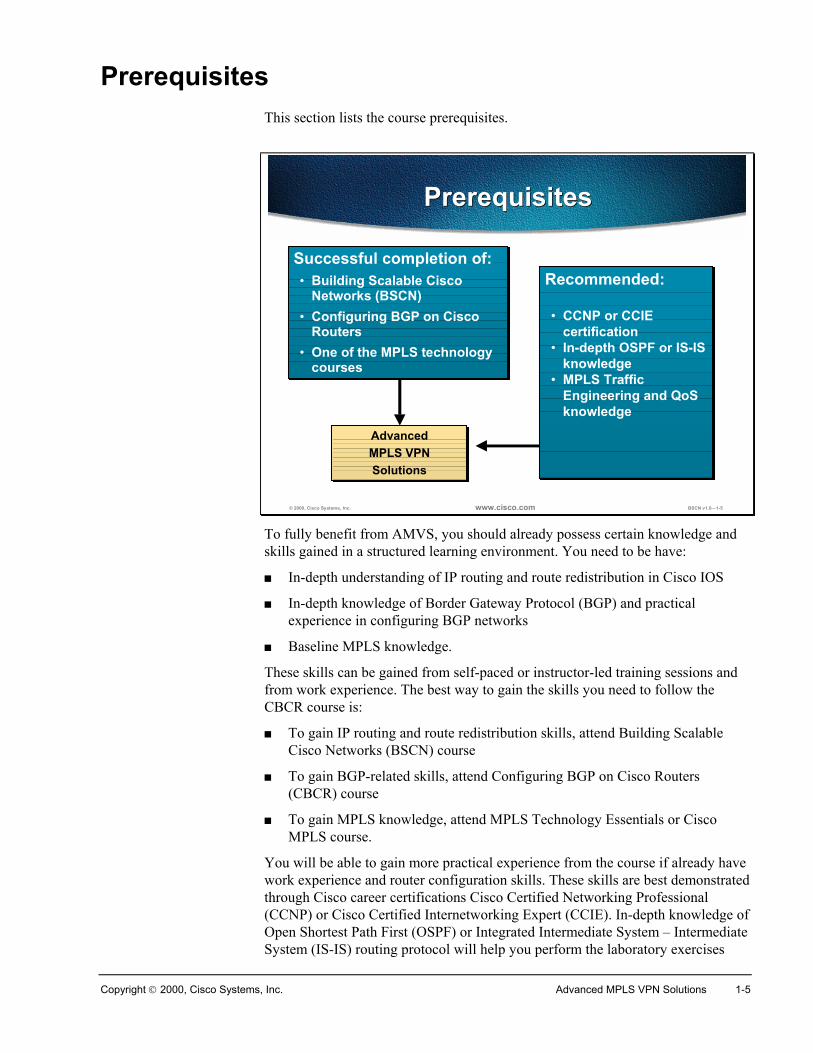
PrerequisitesThis section lists the course prerequisites.
© 2000, Cisco Systems, Inc. www.cisco.com BSCN v1.0—1-5
AdvancedMPLS VPNSolutions
AdvancedMPLS VPNSolutions
PrerequisitesPrerequisites
Successful completion of:• Building Scalable Cisco
Networks (BSCN)• Configuring BGP on Cisco
Routers• One of the MPLS technology
courses
Recommended:
• CCNP or CCIEcertification
• In-depth OSPF or IS-ISknowledge
• MPLS TrafficEngineering and QoSknowledge
To fully benefit from AMVS, you should already possess certain knowledge andskills gained in a structured learning environment. You need to be have:
� In-depth understanding of IP routing and route redistribution in Cisco IOS
� In-depth knowledge of Border Gateway Protocol (BGP) and practicalexperience in configuring BGP networks
� Baseline MPLS knowledge.
These skills can be gained from self-paced or instructor-led training sessions andfrom work experience. The best way to gain the skills you need to follow theCBCR course is:
� To gain IP routing and route redistribution skills, attend Building ScalableCisco Networks (BSCN) course
� To gain BGP-related skills, attend Configuring BGP on Cisco Routers(CBCR) course
� To gain MPLS knowledge, attend MPLS Technology Essentials or CiscoMPLS course.
You will be able to gain more practical experience from the course if already havework experience and router configuration skills. These skills are best demonstratedthrough Cisco career certifications Cisco Certified Networking Professional(CCNP) or Cisco Certified Internetworking Expert (CCIE). In-depth knowledge ofOpen Shortest Path First (OSPF) or Integrated Intermediate System – IntermediateSystem (IS-IS) routing protocol will help you perform the laboratory exercises
1-6 Advanced MPLS VPN Solutions Copyright 2000, Cisco Systems, Inc.
better. MPLS Traffic Engineering and MPLS Quality of Service knowledge willhelp you understand how these technologies relate to MPLS VPN.
Copyright 2000, Cisco Systems, Inc. Advanced MPLS VPN Solutions 1-7
Participant RoleThis section discusses your responsibilities as a student.
© 2000, Cisco Systems, Inc. www.cisco.com BSCN v1.0—1-6
Student role• Meet prerequisites
• Introduce yourself
• Ask and answer questions
Participant RoleParticipant Role
To take full advantage of the information presented in this course, you shouldmeet the prerequisites for this class.
Introduce yourself to the instructor and other students who will be working withyou during the five days of this course.
You are encouraged to ask any questions relevant to the course materials.
If you have pertinent questions concerning other Cisco features and products notcovered in this course, please bring these topics up during breaks or after class,and the instructor will try to answer the questions or direct you to an appropriateinformation source.

1-8 Advanced MPLS VPN Solutions Copyright 2000, Cisco Systems, Inc.
© 2000, Cisco Systems, Inc. www.cisco.com BSCN v1.0—1-7
Welcome: PleaseIntroduce YourselfWelcome: Please
Introduce Yourself
• Your name and work location
• Your job responsibilities
• Your internetworking experience
• Your objectives for this week
Introduce yourself, stating your name and the job function you perform at yourwork location.
Briefly describe what experience you have with installing and configuring Ciscorouters, attending Cisco classes, and how your work experience helped you meetthe prerequisites highlighted earlier.
You should also state what you expect to learn from this course.
Copyright 2000, Cisco Systems, Inc. Advanced MPLS VPN Solutions 1-9
General AdministrationThis section highlights miscellaneous administrative tasks that must be addressed.
© 2000, Cisco Systems, Inc. www.cisco.com BSCN v1.0—1-8
General AdministrationGeneral Administration
Class-related• Sign-in sheet• Length and times• Participant materials• Attire
Facilities-related• Rest rooms• Site emergency
procedures• Break and lunch
room locations• Communications
The instructor will discuss the administrative issues in detail so you will knowexactly what to expect from both the class and facilities. The following items willbe discussed:
� Recording your name on a sign-in sheet
� The starting and anticipated ending time of each class day
� What materials you can expect to receive during the class
� The appropriate attire during class attendance
� Rest room locations
� What to do in the event of an emergency
� Class breaks and lunch facilities
� How to send and receive telephone, e-mail, and fax messages
1-10 Advanced MPLS VPN Solutions Copyright 2000, Cisco Systems, Inc.
Sources of InformationThis section identifies additional sources of information.
© 2000, Cisco Systems, Inc. www.cisco.com BSCN v1.0—1-9
Sources of InformationSources of Information
• Student kit
• www.cisco.com
• CD-ROMs
• Cisco Press
Most of the information presented in this course can be found on the CiscoSystems Web site or on CD-ROM. These supporting materials are available inHTML format and as manuals and release notes.
To learn more about the subjects covered in this course, feel free to access thefollowing sources of information:
� Cisco Documentation CD-ROM
� ITM CD-ROM
� Cisco IOS 12.1 Configuration Guide
� Cisco IOS 12.1 Command Reference Guide
Many of these documents can be found at the following URL:
http://www.cisco.com
Cisco Press books and documents can be found at the following URL:
http://www.ciscopress.com
Copyright 2000, Cisco Systems, Inc. Advanced MPLS VPN Solutions 1-11
© 2000, Cisco Systems, Inc. www.cisco.com BSCN v1.0—1-10
Course SyllabusCourse Syllabus
MPLS VPNTechnology
MPLS VPNTopologies
Internet Accessfrom a VPN
MPLS VPN DesignGuidelines
Large-Scale MPLSVPN Deployment
MPLS VPNMigration Strategies
Technology Implementation Solutions
MPLS VPNConfiguration on
IOS platforms
Running OSPFin an MPLS VPN
Environment
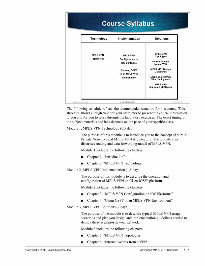
The following schedule reflects the recommended structure for this course. Thisstructure allows enough time for your instructor to present the course informationto you and for you to work through the laboratory exercises. The exact timing ofthe subject materials and labs depends on the pace of your specific class.
Module 1, MPLS VPN Technology (0,5 day)
The purpose of this module is to introduce you to the concept of VirtualPrivate Networks and MPLS VPN Architecture. The module alsodiscusses routing and data forwarding model of MPLS VPN.
Module 1 includes the following chapters:
� Chapter 1, “Introduction”
� Chapter 2, “MPLS VPN Technology”
Module 2, MPLS VPN Implementation (1,5 day)
The purpose of this module is to describe the operation andconfiguration of MPLS VPN on Cisco IOS™ platforms.
Module 2 includes the following chapters:
� Chapter 3, “MPLS VPN Configuration on IOS Platforms”
� Chapter 4, “Using OSPF in an MPLS VPN Environment”
Module 3, MPLS VPN Solutions (2 days)
The purpose of the module is to describe typical MPLS VPN usagescenarios and give you design and implementation guidelines needed todeploy these scenarios in your network.
Module 3 includes the following chapters:
� Chapter 5, “MPLS VPN Topologies”
� Chapter 6, “Internet Access from a VPN”
1-12 Advanced MPLS VPN Solutions Copyright 2000, Cisco Systems, Inc.
� Chapter 7, “MPLS VPN Design Guidelines”
� Chapter 8, “Large-Scale MPLS VPN Deployment”
� Chapter 9, “MPLS VPN Migration Strategies”
2
MPLS VPN Technology
OverviewThis lesson introduces Virtual Private Networks (VPN) and two major VPNdesign options – overlay VPN and peer-to-peer VPN. VPN terminology andtopologies are introduced.
The lesson then describes MPLS VPN architecture, operations and terminology.It details CE-PE routing from various perspectives and BGP extensions (routetargets, and extended community attributes) that allow I-BGP to transportcustomer routes over a provider network. The MPLS VPN forwarding model isalso covered together with its integration with core routing protocols
ObjectivesUpon completion of this lesson, you will be able to perform the following tasks:
� Identify major Virtual Private network topologies, their characteristics andusage scenarios
� Describe the differences between overlay VPN and peer-to-peer VPN
� List major technologies supporting overlay VPNs and peer-to-peer VPNs
� Position MPLS VPN in comparison with other peer-to-peer VPNimplementations
� Describe major architectural blocks of MPLS VPN
� Describe MPLS VPN routing model and packet forwarding
2-2 Advanced MPLS VPN Solutions Copyright 2000, Cisco Systems, Inc.
Introduction to Virtual Private Networks
ObjectivesUpon completion of this section, you will be able to perform the following tasks:
� Describe the concept of VPN
� Understand VPN terminology as defined by MPLS VPN architecture
Copyright 2000, Cisco Systems, Inc. MPLS VPN Technology 2-3
© 2000, Cisco Systems, Inc. www.cisco.com Page5
Traditional Router-Based Networks
Traditional Router-Based Networks
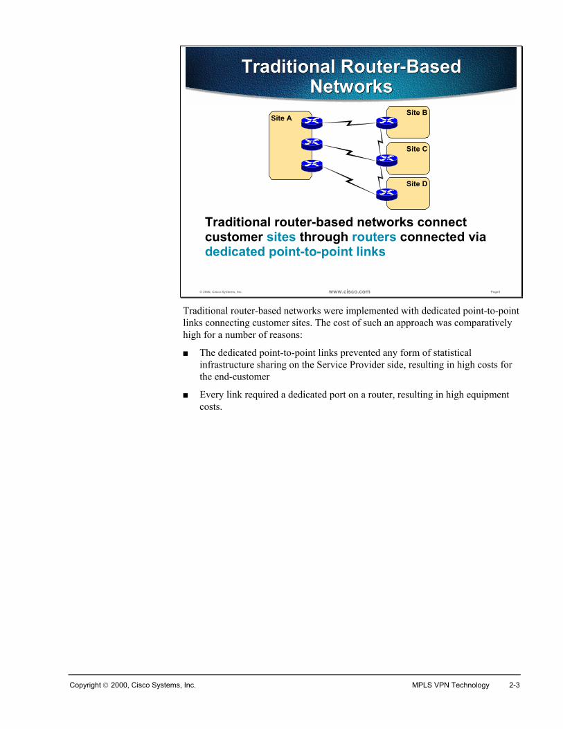
Traditional router-based networks connect customer sites through routers connected via dedicated point-to-point links
Site C
Site BSite A
Site D
Traditional router-based networks were implemented with dedicated point-to-pointlinks connecting customer sites. The cost of such an approach was comparativelyhigh for a number of reasons:
� The dedicated point-to-point links prevented any form of statisticalinfrastructure sharing on the Service Provider side, resulting in high costs forthe end-customer
� Every link required a dedicated port on a router, resulting in high equipmentcosts.
2-4 Advanced MPLS VPN Solutions Copyright 2000, Cisco Systems, Inc.
© 2000, Cisco Systems, Inc. www.cisco.com Page6
Service Provider Network
Virtual Private NetworksVirtual Private Networks
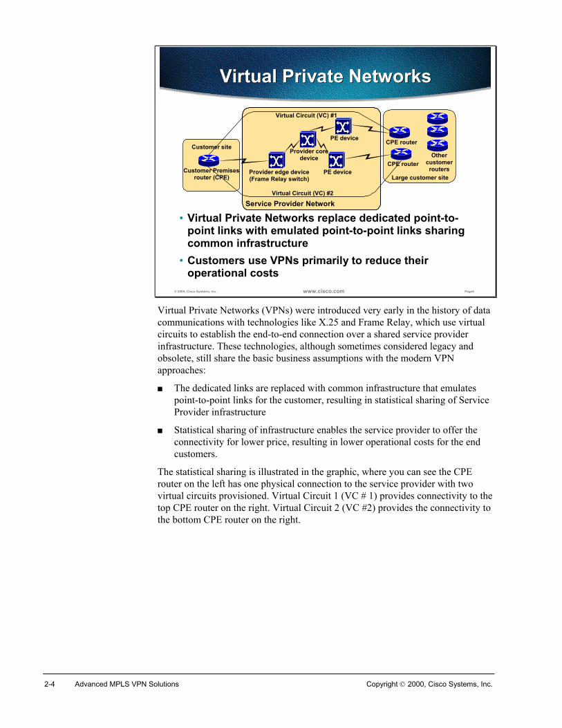
• Virtual Private Networks replace dedicated point-to-point links with emulated point-to-point links sharing common infrastructure
• Customers use VPNs primarily to reduce their operational costs
Customer site
Customer Premisesrouter (CPE) Large customer site
CPE routerOther
customerroutersProvider edge device
(Frame Relay switch)PE device
Provider coredevice
PE device CPE router
Virtual Circuit (VC) #2
Virtual Circuit (VC) #1
Virtual Private Networks (VPNs) were introduced very early in the history of datacommunications with technologies like X.25 and Frame Relay, which use virtualcircuits to establish the end-to-end connection over a shared service providerinfrastructure. These technologies, although sometimes considered legacy andobsolete, still share the basic business assumptions with the modern VPNapproaches:
� The dedicated links are replaced with common infrastructure that emulatespoint-to-point links for the customer, resulting in statistical sharing of ServiceProvider infrastructure
� Statistical sharing of infrastructure enables the service provider to offer theconnectivity for lower price, resulting in lower operational costs for the endcustomers.
The statistical sharing is illustrated in the graphic, where you can see the CPErouter on the left has one physical connection to the service provider with twovirtual circuits provisioned. Virtual Circuit 1 (VC # 1) provides connectivity to thetop CPE router on the right. Virtual Circuit 2 (VC #2) provides the connectivity tothe bottom CPE router on the right.
Copyright 2000, Cisco Systems, Inc. MPLS VPN Technology 2-5
© 2000, Cisco Systems, Inc. www.cisco.com Page7
Customer site
Large customer site
VPN TerminologyVPN Terminology
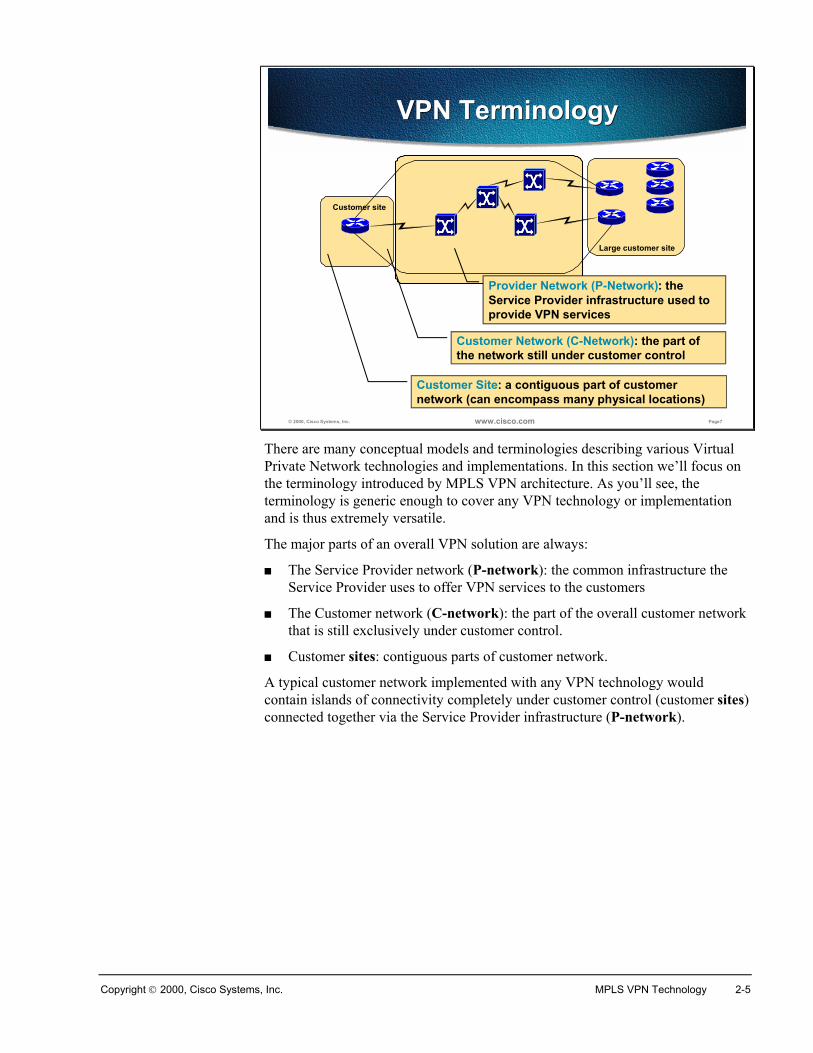
Customer Network (C-Network): the part of the network still under customer control
Provider Network (P-Network): the Service Provider infrastructure used to provide VPN services
Customer Site: a contiguous part of customer network (can encompass many physical locations)
There are many conceptual models and terminologies describing various VirtualPrivate Network technologies and implementations. In this section we’ll focus onthe terminology introduced by MPLS VPN architecture. As you’ll see, theterminology is generic enough to cover any VPN technology or implementationand is thus extremely versatile.
The major parts of an overall VPN solution are always:
� The Service Provider network (P-network): the common infrastructure theService Provider uses to offer VPN services to the customers
� The Customer network (C-network): the part of the overall customer networkthat is still exclusively under customer control.
� Customer sites: contiguous parts of customer network.
A typical customer network implemented with any VPN technology wouldcontain islands of connectivity completely under customer control (customer sites)connected together via the Service Provider infrastructure (P-network).
2-6 Advanced MPLS VPN Solutions Copyright 2000, Cisco Systems, Inc.
© 2000, Cisco Systems, Inc. www.cisco.com Page8
Service Provider Network
Customer site
Large customer site
VPN TerminologyVPN Terminology
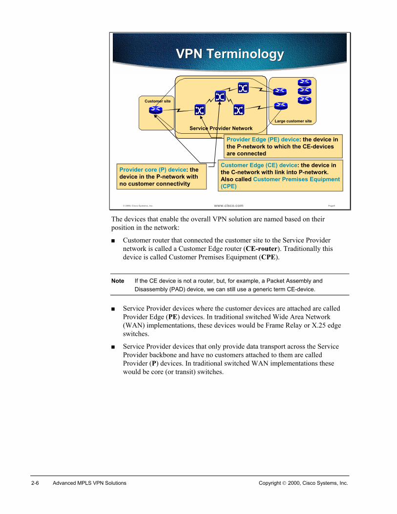
Customer Edge (CE) device: the device in the C-network with link into P-network. Also called Customer Premises Equipment (CPE)
Provider Edge (PE) device: the device in the P-network to which the CE-devices are connected
Provider core (P) device: the device in the P-network with no customer connectivity
The devices that enable the overall VPN solution are named based on theirposition in the network:
� Customer router that connected the customer site to the Service Providernetwork is called a Customer Edge router (CE-router). Traditionally thisdevice is called Customer Premises Equipment (CPE).
Note If the CE device is not a router, but, for example, a Packet Assembly andDisassembly (PAD) device, we can still use a generic term CE-device.
� Service Provider devices where the customer devices are attached are calledProvider Edge (PE) devices. In traditional switched Wide Area Network(WAN) implementations, these devices would be Frame Relay or X.25 edgeswitches.
� Service Provider devices that only provide data transport across the ServiceProvider backbone and have no customers attached to them are calledProvider (P) devices. In traditional switched WAN implementations thesewould be core (or transit) switches.
Copyright 2000, Cisco Systems, Inc. MPLS VPN Technology 2-7
© 2000, Cisco Systems, Inc. www.cisco.com Page9
Service Provider Network
Customer site
Customer PremisesRouter (CPE) Large customer site
CPE routerOther
customerroutersProvider edge device
(Frame Relay switch)PE device
Provider coredevice
PE device CPE router
Virtual Circuit (VC) #2
Virtual Circuit (VC) #1
VPN TerminologySpecific to Switched WAN
VPN TerminologySpecific to Switched WAN
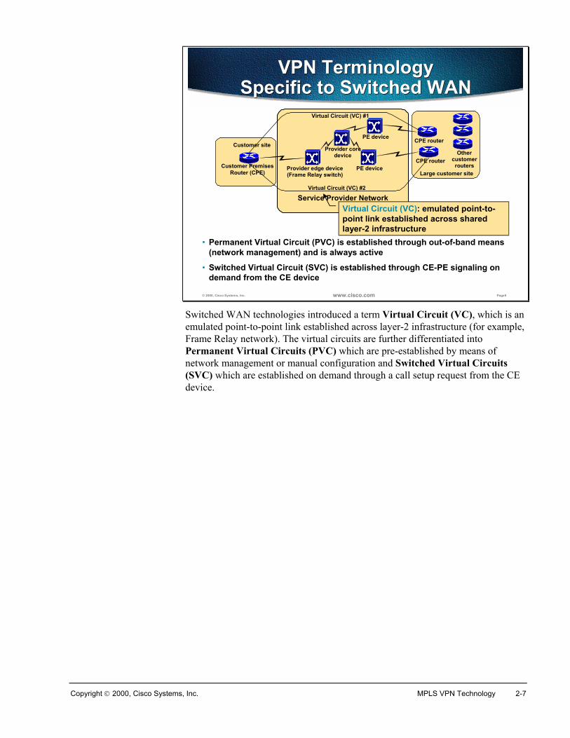
• Permanent Virtual Circuit (PVC) is established through out-of-band means (network management) and is always active
• Switched Virtual Circuit (SVC) is established through CE-PE signaling on demand from the CE device
Virtual Circuit (VC): emulated point-to-point link established across shared layer-2 infrastructure
Switched WAN technologies introduced a term Virtual Circuit (VC), which is anemulated point-to-point link established across layer-2 infrastructure (for example,Frame Relay network). The virtual circuits are further differentiated intoPermanent Virtual Circuits (PVC) which are pre-established by means ofnetwork management or manual configuration and Switched Virtual Circuits(SVC) which are established on demand through a call setup request from the CEdevice.
2-8 Advanced MPLS VPN Solutions Copyright 2000, Cisco Systems, Inc.
SummaryVirtual Private Networks were introduced by Service Providers to offer a morecost-effective alternative to traditional customer network design, which relied ondedicated point-to-point links between customer sites.
The overall network implemented with a VPN solution is divided into theCustomer network (C-network), which is exclusively under customer’s controland the Provider network (P-network), the shared infrastructure used to offer theVPN services. A contiguous part of the C-network is called a customer site.
The device linking a customer site with the P-network is called Customer Edge(CE) device. Most commonly this is a router, called CE-router. This componentwas traditionally named Customer Premises Equipment (CPE).
The edge device in Service Provider network, to which the customers are attached,is called Provider Edge (PE) device. The device inside the Provider network withno customer connectivity is a Provider (P) device.
Review QuestionsAnswer the following questions:
� Why are customers interested in Virtual Private Networks?
� What is the main role of a VPN?
� What is a C-network?
� What is a customer site?
� What is a CE-router?
� What is a P-network?
� What is the difference between a PE-device and a P-device?
Copyright 2000, Cisco Systems, Inc. MPLS VPN Technology 2-9
Overlay and Peer-to-Peer VPN
ObjectivesUpon completion of this section, you will be able to perform the following tasks:
� Describe the differences between overlay and peer-to-peer VPN
� Describe the benefits and drawbacks of each VPN implementation option
� List major technologies supporting overlay VPNs
� Describe traditional peer-to-peer VPN implementation options
2-10 Advanced MPLS VPN Solutions Copyright 2000, Cisco Systems, Inc.
© 2000, Cisco Systems, Inc. www.cisco.com Page14
VPN Implementation Technologies
VPN Implementation Technologies
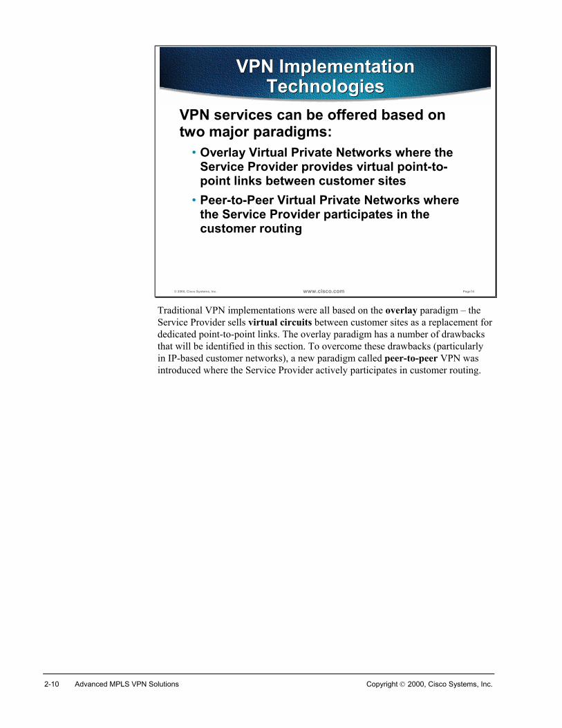
VPN services can be offered based on two major paradigms:
• Overlay Virtual Private Networks where the Service Provider provides virtual point-to-point links between customer sites
• Peer-to-Peer Virtual Private Networks where the Service Provider participates in the customer routing
Traditional VPN implementations were all based on the overlay paradigm – theService Provider sells virtual circuits between customer sites as a replacement fordedicated point-to-point links. The overlay paradigm has a number of drawbacksthat will be identified in this section. To overcome these drawbacks (particularlyin IP-based customer networks), a new paradigm called peer-to-peer VPN wasintroduced where the Service Provider actively participates in customer routing.
Copyright 2000, Cisco Systems, Inc. MPLS VPN Technology 2-11
© 2000, Cisco Systems, Inc. www.cisco.com Page15
Service Provider Network
Overlay VPN Implementation(Frame Relay Example)
Overlay VPN Implementation(Frame Relay Example)
Customer Site
Router A
Customer Site
Router B
Customer Site
Router C
Customer Site
Router D
Provider Edge Device(Frame Relay Switch)
Frame RelayEdge Switch
Frame RelayEdge Switch
Frame RelayEdge Switch
Virtual Circuit (VC) #3
Virtual Circuit (VC) #2
(VC) #1
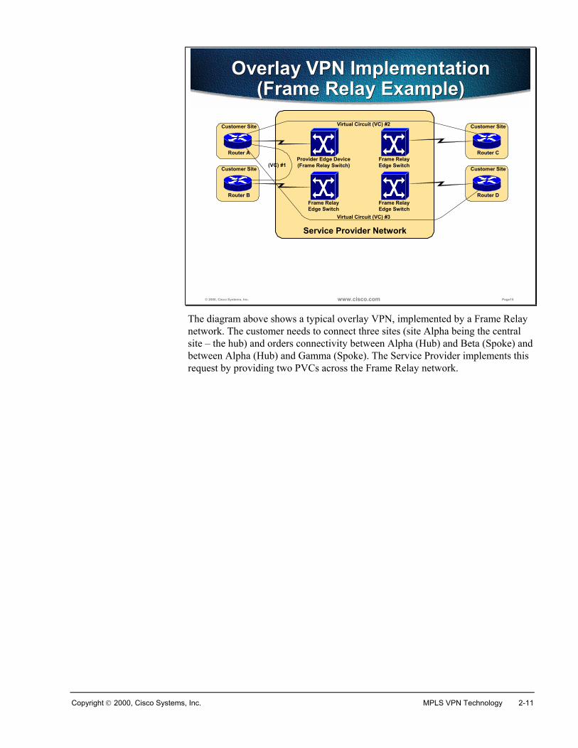
The diagram above shows a typical overlay VPN, implemented by a Frame Relaynetwork. The customer needs to connect three sites (site Alpha being the centralsite – the hub) and orders connectivity between Alpha (Hub) and Beta (Spoke) andbetween Alpha (Hub) and Gamma (Spoke). The Service Provider implements thisrequest by providing two PVCs across the Frame Relay network.
2-12 Advanced MPLS VPN Solutions Copyright 2000, Cisco Systems, Inc.
© 2000, Cisco Systems, Inc. www.cisco.com Page16
Layer-3 routing in Overlay VPN implementation
Layer-3 routing in Overlay VPN implementation
• Service Provider infrastructure appears as point-to-point links to customer routes
• Routing protocols run directly between customer routers
• Service Provider does not see customer routes and is responsible only for providing point-to-point transport of customer data
Router A
Router B Router C Router D
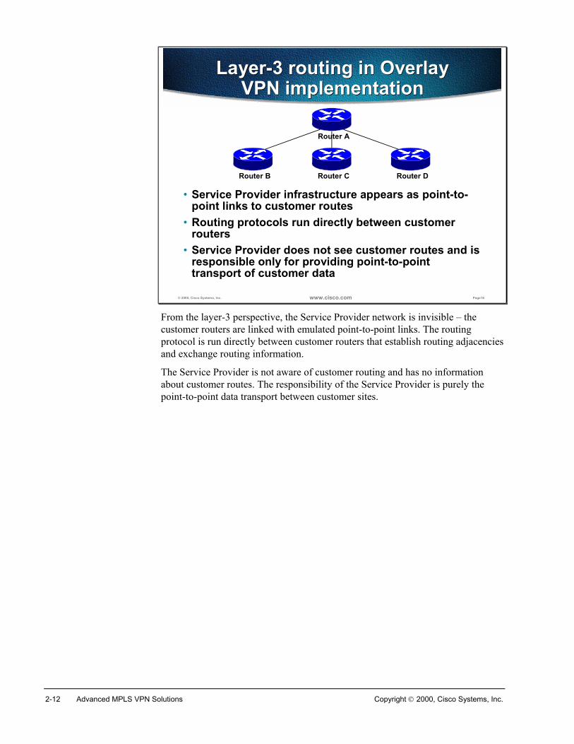
From the layer-3 perspective, the Service Provider network is invisible – thecustomer routers are linked with emulated point-to-point links. The routingprotocol is run directly between customer routers that establish routing adjacenciesand exchange routing information.
The Service Provider is not aware of customer routing and has no informationabout customer routes. The responsibility of the Service Provider is purely thepoint-to-point data transport between customer sites.
Copyright 2000, Cisco Systems, Inc. MPLS VPN Technology 2-13
Overlay VPN ImplementationsThere are a number of different overlay VPN implementations, ranging fromtraditional Time Division Multiplexing (TDM) to highly complex technologiesrunning across IP backbones. In the following slides, we’ll introduce major VPNtechnologies and implementations.
© 2000, Cisco Systems, Inc. www.cisco.com Page17
Overlay VPNLayer-1 Implementation
Overlay VPNLayer-1 Implementation
This is the traditional TDM solution:• Service Provider establishes physical-layer
connectivity between customer sites• Customer takes responsibility for all higher layers
ISDN E1, T1, DS0 SDH, SONET
PPP HDLC
IP
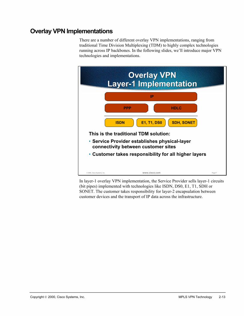
In layer-1 overlay VPN implementation, the Service Provider sells layer-1 circuits(bit pipes) implemented with technologies like ISDN, DS0, E1, T1, SDH orSONET. The customer takes responsibility for layer-2 encapsulation betweencustomer devices and the transport of IP data across the infrastructure.
2-14 Advanced MPLS VPN Solutions Copyright 2000, Cisco Systems, Inc.
© 2000, Cisco Systems, Inc. www.cisco.com Page18
Overlay VPNLayer-2 Implementation
Overlay VPNLayer-2 Implementation
This is the traditional Switched WAN solution:• Service Provider establishes layer-2 virtual circuits
between customer sites• Customer takes responsibility for all higher layers
X.25 Frame Relay ATM
IP
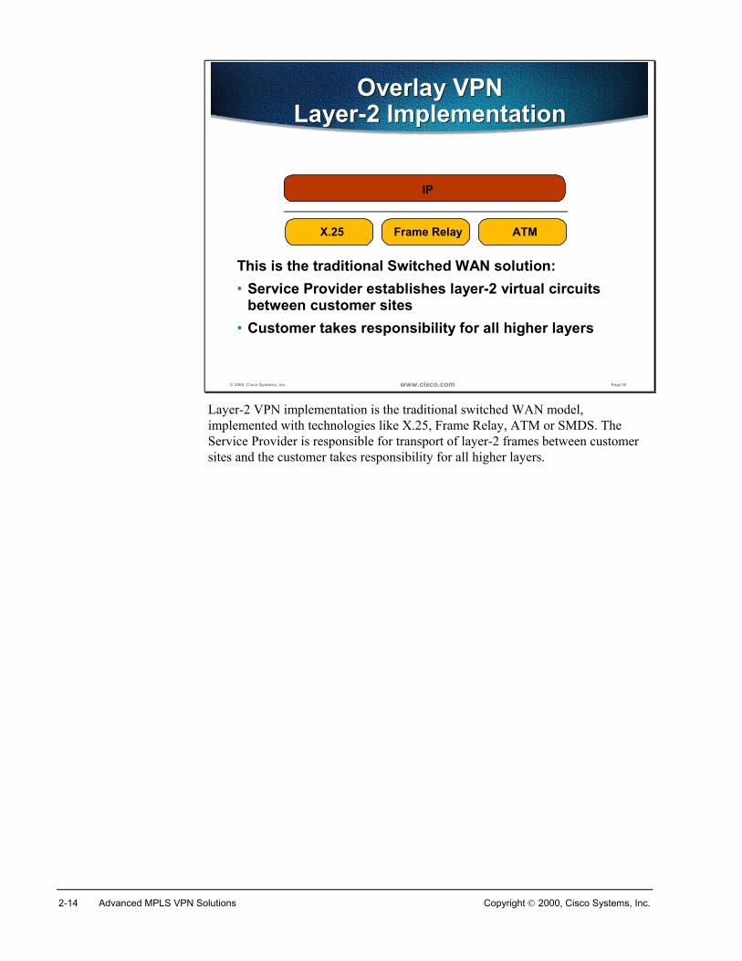
Layer-2 VPN implementation is the traditional switched WAN model,implemented with technologies like X.25, Frame Relay, ATM or SMDS. TheService Provider is responsible for transport of layer-2 frames between customersites and the customer takes responsibility for all higher layers.
Copyright 2000, Cisco Systems, Inc. MPLS VPN Technology 2-15
© 2000, Cisco Systems, Inc. www.cisco.com Page19
Overlay VPNIP TunnelingOverlay VPNIP Tunneling
VPN is implemented with IP-over-IP tunnels• Tunnels are established with GRE or IPSec• GRE is simpler (and quicker), IPSec provides
authentication and security
Generic Route Encapsulation (GRE) IP Security (IPSec)
Internet Protocol (IP)
Internet Protocol (IP)
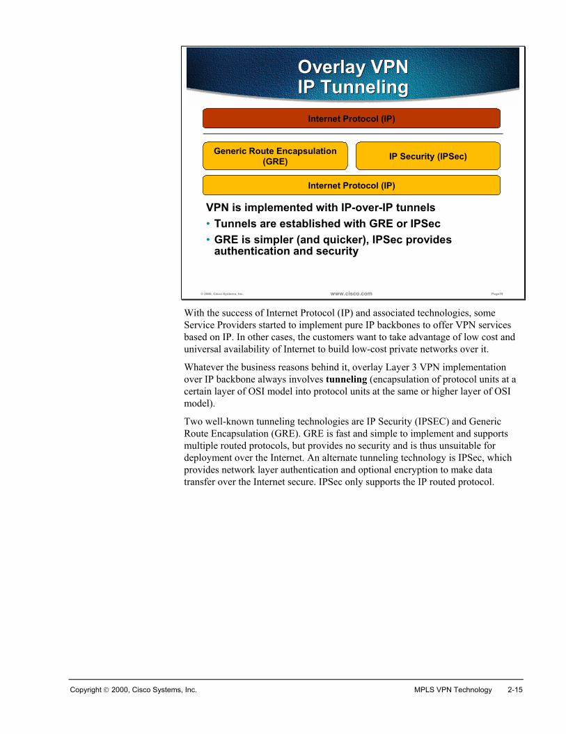
With the success of Internet Protocol (IP) and associated technologies, someService Providers started to implement pure IP backbones to offer VPN servicesbased on IP. In other cases, the customers want to take advantage of low cost anduniversal availability of Internet to build low-cost private networks over it.
Whatever the business reasons behind it, overlay Layer 3 VPN implementationover IP backbone always involves tunneling (encapsulation of protocol units at acertain layer of OSI model into protocol units at the same or higher layer of OSImodel).
Two well-known tunneling technologies are IP Security (IPSEC) and GenericRoute Encapsulation (GRE). GRE is fast and simple to implement and supportsmultiple routed protocols, but provides no security and is thus unsuitable fordeployment over the Internet. An alternate tunneling technology is IPSec, whichprovides network layer authentication and optional encryption to make datatransfer over the Internet secure. IPSec only supports the IP routed protocol.
2-16 Advanced MPLS VPN Solutions Copyright 2000, Cisco Systems, Inc.
© 2000, Cisco Systems, Inc. www.cisco.com Page20
Overlay VPNLayer-2 Forwarding
Overlay VPNLayer-2 Forwarding
VPN is implemented with PPP-over-IP tunnels• Usually used in access environments (dial-up, DSL)
Layer-2 Transport Protocol (L2TP)
Internet Protocol (IP)
Point-to-Point Protocol (PPP)
Layer-2 Forwarding (L2F)
Point-to-Point Tunneling (PPTP)
Internet Protocol (IP)
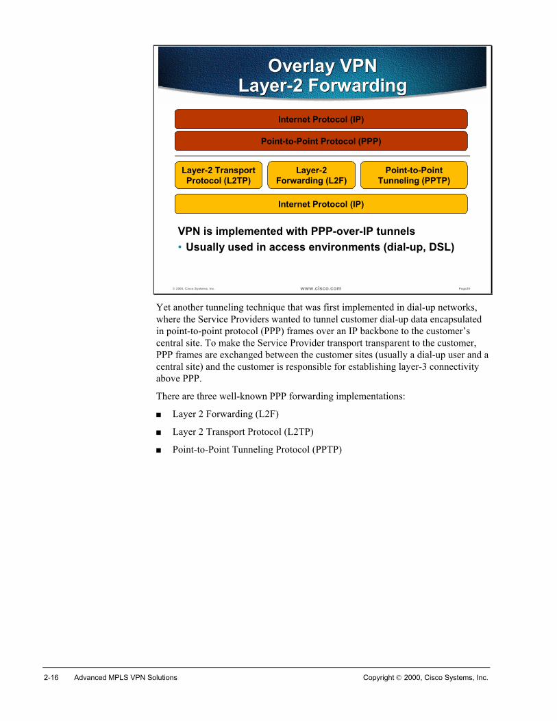
Yet another tunneling technique that was first implemented in dial-up networks,where the Service Providers wanted to tunnel customer dial-up data encapsulatedin point-to-point protocol (PPP) frames over an IP backbone to the customer’scentral site. To make the Service Provider transport transparent to the customer,PPP frames are exchanged between the customer sites (usually a dial-up user and acentral site) and the customer is responsible for establishing layer-3 connectivityabove PPP.
There are three well-known PPP forwarding implementations:
� Layer 2 Forwarding (L2F)
� Layer 2 Transport Protocol (L2TP)
� Point-to-Point Tunneling Protocol (PPTP)
Copyright 2000, Cisco Systems, Inc. MPLS VPN Technology 2-17
© 2000, Cisco Systems, Inc. www.cisco.com Page21
Service Provider Network
Peer-to-Peer VPN ConceptPeer-to-Peer VPN Concept
Customer Site
Router A
Customer Site
Router B
Customer Site
Router C
Customer Site
Router D
Provider Edge (PE)Router
(PE) Router
(PE) Router
(PE) Router
Routing information is exchanged between customer and service-provider routers
Service Provider routers exchange customer routes through the core network
Finally, the customer routes propagated through the service-provider network are
sent to other customer routers
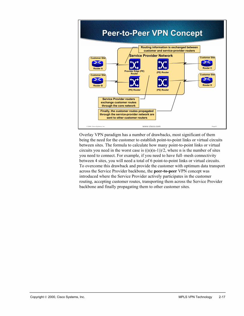
Overlay VPN paradigm has a number of drawbacks, most significant of thembeing the need for the customer to establish point-to-point links or virtual circuitsbetween sites. The formula to calculate how many point-to-point links or virtualcircuits you need in the worst case is ((n)(n-1))/2, where n is the number of sitesyou need to connect. For example, if you need to have full–mesh connectivitybetween 4 sites, you will need a total of 6 point-to-point links or virtual circuits.To overcome this drawback and provide the customer with optimum data transportacross the Service Provider backbone, the peer-to-peer VPN concept wasintroduced where the Service Provider actively participates in the customerrouting, accepting customer routes, transporting them across the Service Providerbackbone and finally propagating them to other customer sites.
2-18 Advanced MPLS VPN Solutions Copyright 2000, Cisco Systems, Inc.
© 2000, Cisco Systems, Inc. www.cisco.com Page22
Peer-to-Peer VPN with Packet Filters
Peer-to-Peer VPN with Packet Filters
Service provider networkCustomer ASite #1
Customer ASite #2
Customer BSite #1
Point-of-Presence
Shared router
POP router carries all customer routes
Isolation between customers is achieved with packet filters on PE-CE interfaces
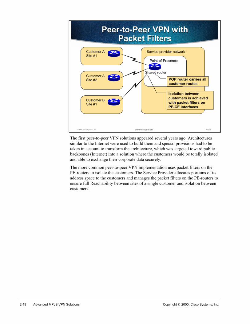
The first peer-to-peer VPN solutions appeared several years ago. Architecturessimilar to the Internet were used to build them and special provisions had to betaken in account to transform the architecture, which was targeted toward publicbackbones (Internet) into a solution where the customers would be totally isolatedand able to exchange their corporate data securely.
The more common peer-to-peer VPN implementation uses packet filters on thePE-routers to isolate the customers. The Service Provider allocates portions of itsaddress space to the customers and manages the packet filters on the PE-routers toensure full Reachability between sites of a single customer and isolation betweencustomers.
Copyright 2000, Cisco Systems, Inc. MPLS VPN Technology 2-19
© 2000, Cisco Systems, Inc. www.cisco.com Page23
Peer-to-Peer VPN with Controlled Route Distribution
Peer-to-Peer VPN with Controlled Route Distribution
Service provider networkCustomer ASite #1
Customer ASite #2
Customer BSite #1
Point-of-Presence
PE-routerCustomer-A
PE-routerCustomer-B
P-router
Uplink
Each customer has a dedicated PE router that only carries its routes
The P-router contains all customer routes
Customer isolation is achieved through lack of routing information on PE router
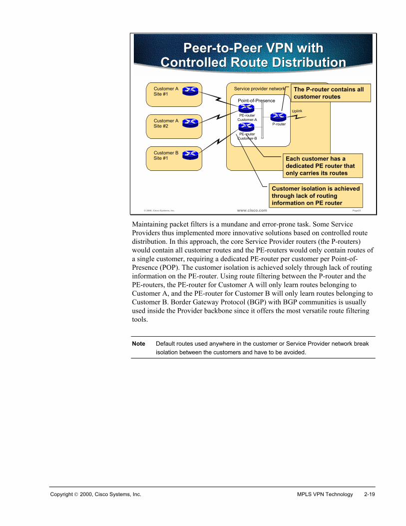
Maintaining packet filters is a mundane and error-prone task. Some ServiceProviders thus implemented more innovative solutions based on controlled routedistribution. In this approach, the core Service Provider routers (the P-routers)would contain all customer routes and the PE-routers would only contain routes ofa single customer, requiring a dedicated PE-router per customer per Point-of-Presence (POP). The customer isolation is achieved solely through lack of routinginformation on the PE-router. Using route filtering between the P-router and thePE-routers, the PE-router for Customer A will only learn routes belonging toCustomer A, and the PE-router for Customer B will only learn routes belonging toCustomer B. Border Gateway Protocol (BGP) with BGP communities is usuallyused inside the Provider backbone since it offers the most versatile route filteringtools.
Note Default routes used anywhere in the customer or Service Provider network breakisolation between the customers and have to be avoided.
2-20 Advanced MPLS VPN Solutions Copyright 2000, Cisco Systems, Inc.
© 2000, Cisco Systems, Inc. www.cisco.com Page24
Benefits of Various VPN Implementations
Benefits of Various VPN Implementations
Overlay VPN• Well-known and easy to
implement• Service Provider does
not participate in customer routing
• Customer network and Service Provider network are well isolated
Peer-to-Peer VPN• Guarantees optimum
routing between customer sites
• Easier to provision an additional VPN
• Only the sites are provisioned, not the links between them
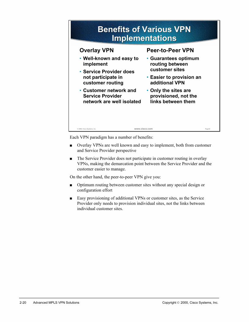
Each VPN paradigm has a number of benefits:
� Overlay VPNs are well known and easy to implement, both from customerand Service Provider perspective
� The Service Provider does not participate in customer routing in overlayVPNs, making the demarcation point between the Service Provider and thecustomer easier to manage.
On the other hand, the peer-to-peer VPN give you:
� Optimum routing between customer sites without any special design orconfiguration effort
� Easy provisioning of additional VPNs or customer sites, as the ServiceProvider only needs to provision individual sites, not the links betweenindividual customer sites.
Copyright 2000, Cisco Systems, Inc. MPLS VPN Technology 2-21
© 2000, Cisco Systems, Inc. www.cisco.com Page25
Drawbacks of Various VPN Implementations
Drawbacks of Various VPN Implementations
Overlay VPN• Implementing optimum
routing requires full-mesh of virtual circuits
• Virtual circuits have to be provisioned manually
• Bandwidth must be provisioned on a site-to-site basis
• Always incurs encapsulation overhead
Peer-to-Peer VPN• Service Provider
participates in customer routing
• SP becomes responsible for customer convergence
• PE routers carry all routes from all customers
• SP needs detailed IP routing knowledge
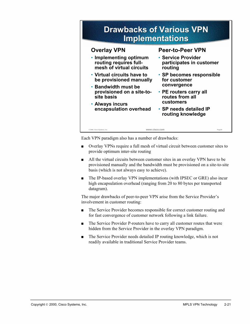
Each VPN paradigm also has a number of drawbacks:
� Overlay VPNs require a full mesh of virtual circuit between customer sites toprovide optimum inter-site routing
� All the virtual circuits between customer sites in an overlay VPN have to beprovisioned manually and the bandwidth must be provisioned on a site-to-sitebasis (which is not always easy to achieve).
� The IP-based overlay VPN implementations (with IPSEC or GRE) also incurhigh encapsulation overhead (ranging from 20 to 80 bytes per transporteddatagram).
The major drawbacks of peer-to-peer VPN arise from the Service Provider’sinvolvement in customer routing:
� The Service Provider becomes responsible for correct customer routing andfor fast convergence of customer network following a link failure.
� The Service Provider P-routers have to carry all customer routes that werehidden from the Service Provider in the overlay VPN paradigm.
� The Service Provider needs detailed IP routing knowledge, which is notreadily available in traditional Service Provider teams.
2-22 Advanced MPLS VPN Solutions Copyright 2000, Cisco Systems, Inc.
© 2000, Cisco Systems, Inc. www.cisco.com Page26
Drawbacks of Traditional Peer-to-Peer VPNs
Drawbacks of Traditional Peer-to-Peer VPNs
Shared PE router• All customers share the
same (provider-assigned or public) address space
• High maintenance costs associated with packet filters
• Lower performance—each packet has to pass a packet filter
Dedicated PE router• All customers share the
same address space• Each customer requires
a dedicated router at each POP
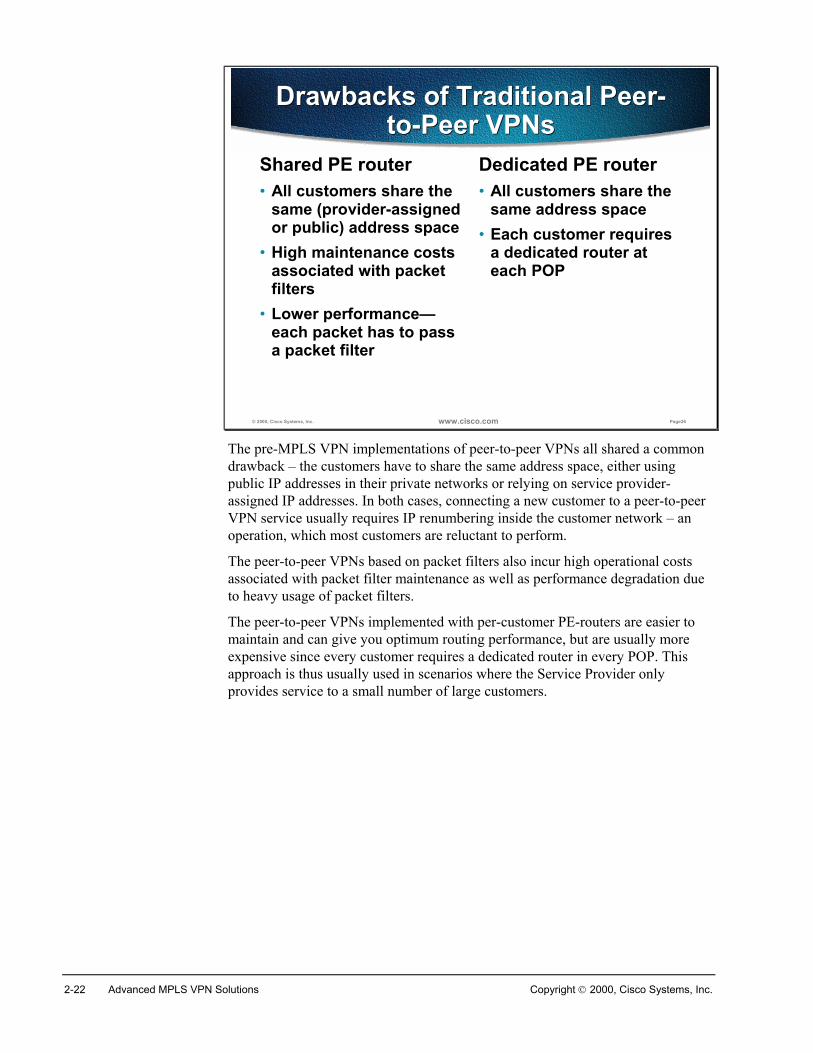
The pre-MPLS VPN implementations of peer-to-peer VPNs all shared a commondrawback – the customers have to share the same address space, either usingpublic IP addresses in their private networks or relying on service provider-assigned IP addresses. In both cases, connecting a new customer to a peer-to-peerVPN service usually requires IP renumbering inside the customer network – anoperation, which most customers are reluctant to perform.
The peer-to-peer VPNs based on packet filters also incur high operational costsassociated with packet filter maintenance as well as performance degradation dueto heavy usage of packet filters.
The peer-to-peer VPNs implemented with per-customer PE-routers are easier tomaintain and can give you optimum routing performance, but are usually moreexpensive since every customer requires a dedicated router in every POP. Thisapproach is thus usually used in scenarios where the Service Provider onlyprovides service to a small number of large customers.
Copyright 2000, Cisco Systems, Inc. MPLS VPN Technology 2-23
Summary
© 2000, Cisco Systems, Inc. www.cisco.com Page27
VPN TaxonomyVPN TaxonomyVirtual NetworksVirtual Dialup Networks Virtual LANsVirtual Private
Networks
Peer-to-Peer VPN
Access Lists(Shared Router)
Split Routing(Dedicated Router)
MPLS VPN
Overlay VPN
Layer 2 VPN Layer 3 VPN
X.25
F/R
ATM
IPSec
GRE
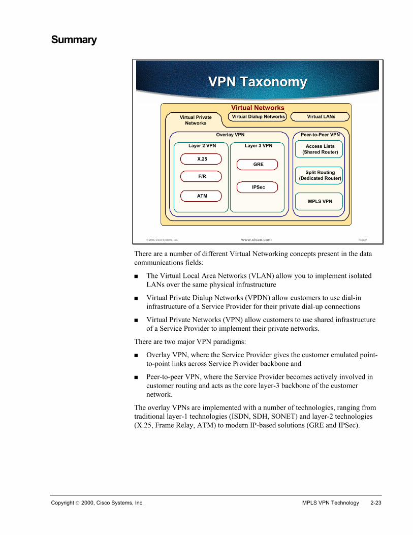
There are a number of different Virtual Networking concepts present in the datacommunications fields:
� The Virtual Local Area Networks (VLAN) allow you to implement isolatedLANs over the same physical infrastructure
� Virtual Private Dialup Networks (VPDN) allow customers to use dial-ininfrastructure of a Service Provider for their private dial-up connections
� Virtual Private Networks (VPN) allow customers to use shared infrastructureof a Service Provider to implement their private networks.
There are two major VPN paradigms:
� Overlay VPN, where the Service Provider gives the customer emulated point-to-point links across Service Provider backbone and
� Peer-to-peer VPN, where the Service Provider becomes actively involved incustomer routing and acts as the core layer-3 backbone of the customernetwork.
The overlay VPNs are implemented with a number of technologies, ranging fromtraditional layer-1 technologies (ISDN, SDH, SONET) and layer-2 technologies(X.25, Frame Relay, ATM) to modern IP-based solutions (GRE and IPSec).
2-24 Advanced MPLS VPN Solutions Copyright 2000, Cisco Systems, Inc.
The overlay VPNs, although well known and easy to implement, are harder tooperate due to higher maintenance costs:
� Every individual virtual circuit needs to be provisioned
� Optimum routing between customer sites requires a full mesh of virtualcircuits between sites
� Bandwidth has to be provisioned on site-to-site basis.
Traditional peer-to-peer VPNs are implemented with packet filters on shared PE-routers or with dedicated per-customer PE-routers. Along with high maintenancecosts (for packet-filter approach) or equipment costs (for dedicated per-customerPE-router approach), both methods require customer to accept the ServiceProvider assigned address space or use public IP addresses in the private customernetwork.
MPLS VPN, introduced in the next sections, provides all the benefits of peer-to-peer VPNs and alleviates most of the peer-to-peer VPN drawbacks (for example,the need for common customer address space).
Review QuestionsAnswer the following questions:
� What is an overlay VPN?
� Which routing protocol runs between the customer and the service provider inan overlay VPN?
� Which routers are routing protocol neighbors of a CE-router in overlay VPN?
� List three IP-based overlay VPN technologies.
� What is the major benefit of peer-to-peer VPN as compared to overlay VPN?
� List two traditional peer-to-peer VPN implementations?
� What is the drawback of all traditional peer-to-peer VPN implementations?
Copyright 2000, Cisco Systems, Inc. MPLS VPN Technology 2-25
Major VPN Topologies
ObjectivesUpon completion of this section, you will be able to perform the following tasks:
� Identify the three major categorizations of VPN
� Identify the three Overlay VPN topologies
� Understand the implications of using overlay VPN approach with eachtopology
� List sample usage scenarios for each topology
� Identify the three VPN categorization based on business needs
� Identify the three VPN categorization based on connectivity needs
VPN Categorizations
There are three major VPN categorizations:
� Topology categorization, which only applies to overlay VPNs
� Business categorization, which categorizes VPNs based on the business needsthey fulfill
� Connectivity categorization, which classifies VPNs based on theirconnectivity requirements.
2-26 Advanced MPLS VPN Solutions Copyright 2000, Cisco Systems, Inc.
© 2000, Cisco Systems, Inc. www.cisco.com Page32
VPN Topology CategorizationVPN Topology Categorization
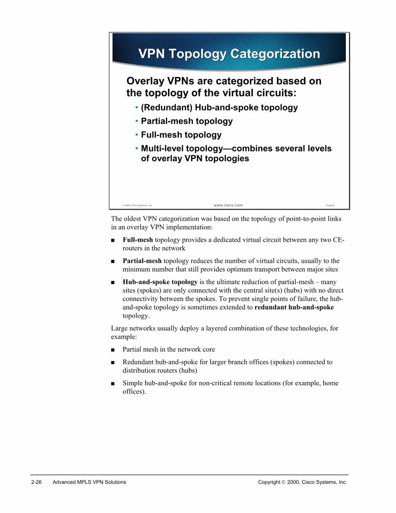
Overlay VPNs are categorized based on the topology of the virtual circuits:
• (Redundant) Hub-and-spoke topology• Partial-mesh topology• Full-mesh topology• Multi-level topology—combines several levels
of overlay VPN topologies
The oldest VPN categorization was based on the topology of point-to-point linksin an overlay VPN implementation:
� Full-mesh topology provides a dedicated virtual circuit between any two CE-routers in the network
� Partial-mesh topology reduces the number of virtual circuits, usually to theminimum number that still provides optimum transport between major sites
� Hub-and-spoke topology is the ultimate reduction of partial-mesh – manysites (spokes) are only connected with the central site(s) (hubs) with no directconnectivity between the spokes. To prevent single points of failure, the hub-and-spoke topology is sometimes extended to redundant hub-and-spoketopology.
Large networks usually deploy a layered combination of these technologies, forexample:
� Partial mesh in the network core
� Redundant hub-and-spoke for larger branch offices (spokes) connected todistribution routers (hubs)
� Simple hub-and-spoke for non-critical remote locations (for example, homeoffices).
Copyright 2000, Cisco Systems, Inc. MPLS VPN Technology 2-27
© 2000, Cisco Systems, Inc. www.cisco.com Page33
Service Provider Network
Overlay VPNHub-and-Spoke Topology
Overlay VPNHub-and-Spoke Topology
Central site(HUB)
Remote site (spoke)
Remote site (spoke)
Remote site (spoke)Central site
router
Remote site (spoke)
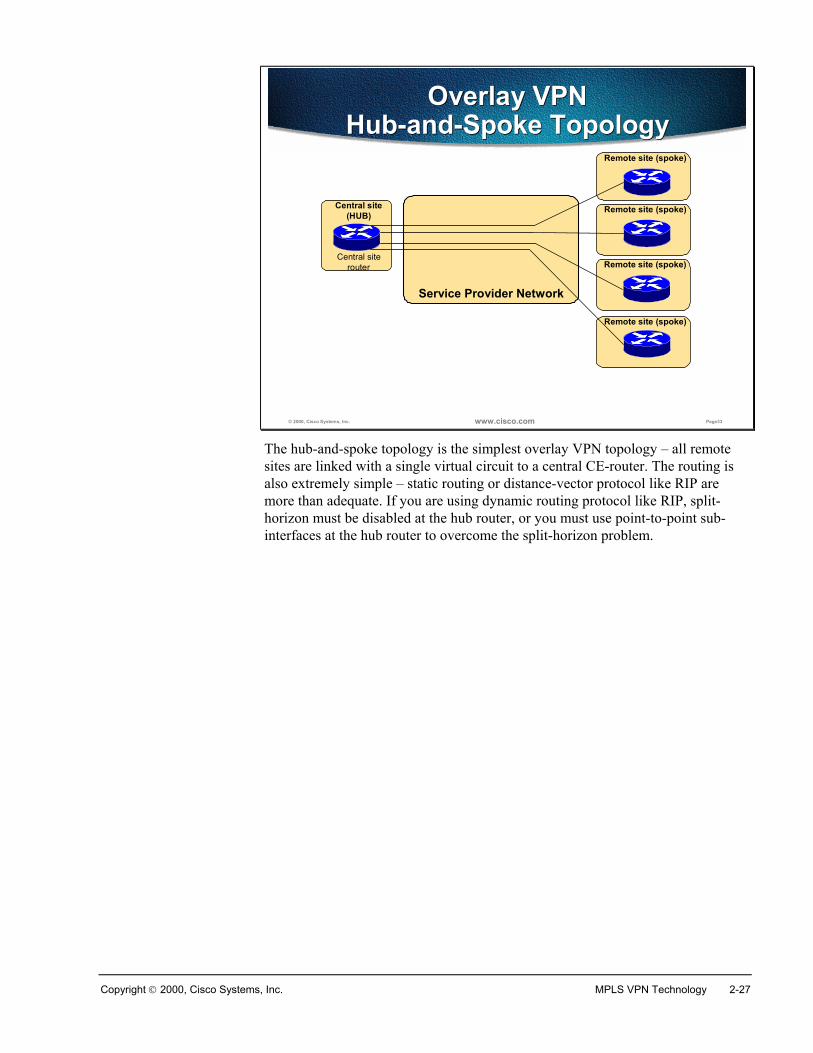
The hub-and-spoke topology is the simplest overlay VPN topology – all remotesites are linked with a single virtual circuit to a central CE-router. The routing isalso extremely simple – static routing or distance-vector protocol like RIP aremore than adequate. If you are using dynamic routing protocol like RIP, split-horizon must be disabled at the hub router, or you must use point-to-point sub-interfaces at the hub router to overcome the split-horizon problem.
2-28 Advanced MPLS VPN Solutions Copyright 2000, Cisco Systems, Inc.
© 2000, Cisco Systems, Inc. www.cisco.com Page34
Service Provider Network
Overlay VPNRedundant Hub-And-Spoke
Overlay VPNRedundant Hub-And-Spoke
Central site(HUB)
Remote site (spoke)
Remote site (spoke)
Remote site (spoke)RedundantCentral site
router
Remote site (spoke)RedundantCentral site
router
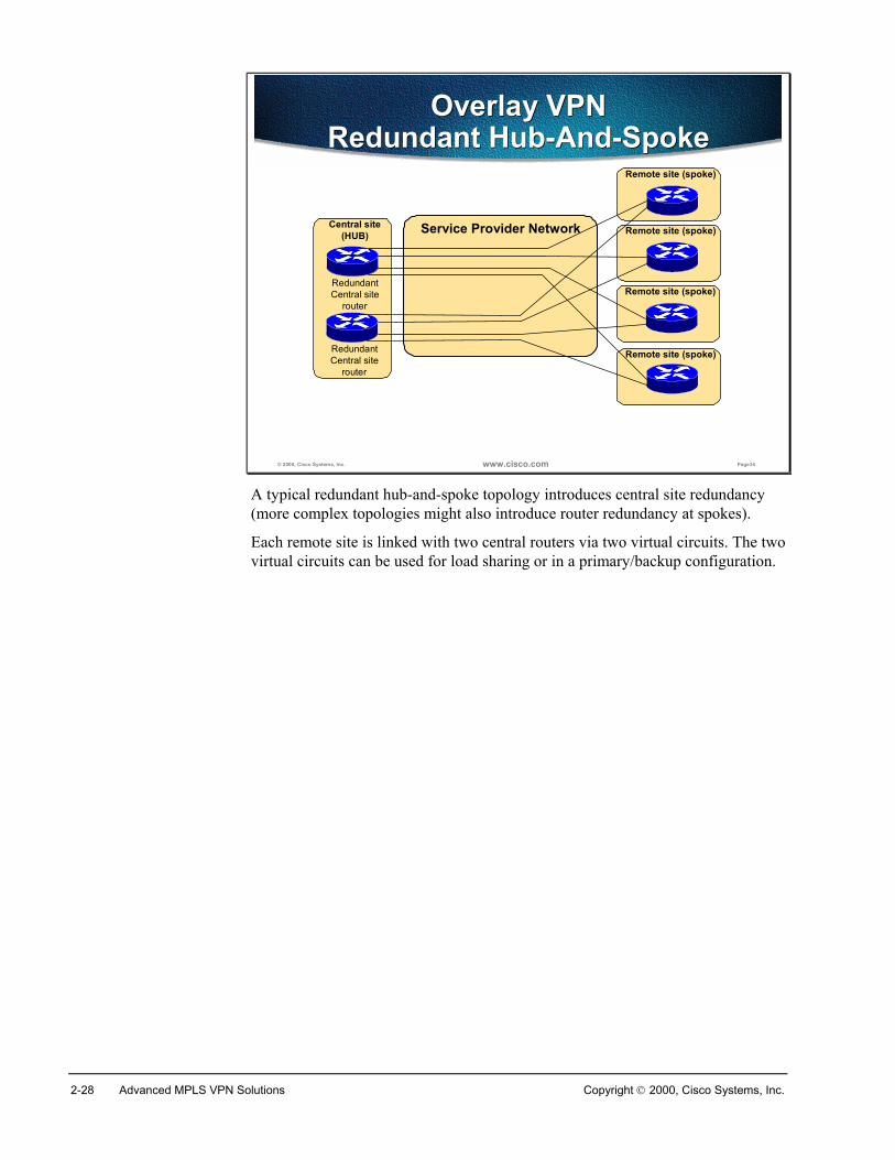
A typical redundant hub-and-spoke topology introduces central site redundancy(more complex topologies might also introduce router redundancy at spokes).
Each remote site is linked with two central routers via two virtual circuits. The twovirtual circuits can be used for load sharing or in a primary/backup configuration.
Copyright 2000, Cisco Systems, Inc. MPLS VPN Technology 2-29
© 2000, Cisco Systems, Inc. www.cisco.com Page35
Overlay VPNPartial MeshOverlay VPNPartial Mesh
Moscow
Sydney
Guam
Berlin
Hong Kong
New York
Virtual circuits (Frame Relay DLCI)
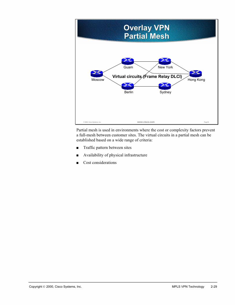
Partial mesh is used in environments where the cost or complexity factors preventa full-mesh between customer sites. The virtual circuits in a partial mesh can beestablished based on a wide range of criteria:
� Traffic pattern between sites
� Availability of physical infrastructure
� Cost considerations
2-30 Advanced MPLS VPN Solutions Copyright 2000, Cisco Systems, Inc.
© 2000, Cisco Systems, Inc. www.cisco.com Page36
Service Provider Network
Overlay VPNMulti-Level Hub-and-Spoke
Overlay VPNMulti-Level Hub-and-Spoke
Central site (hub)
Remote site (spoke)
Remote site (spoke)
Remote site (spoke)
Redundant centralsite router
Redundant centralsite router
Distribution site
Distribution-layerrouter
Distribution site
Distribution-layerrouter
Remote site (spoke)
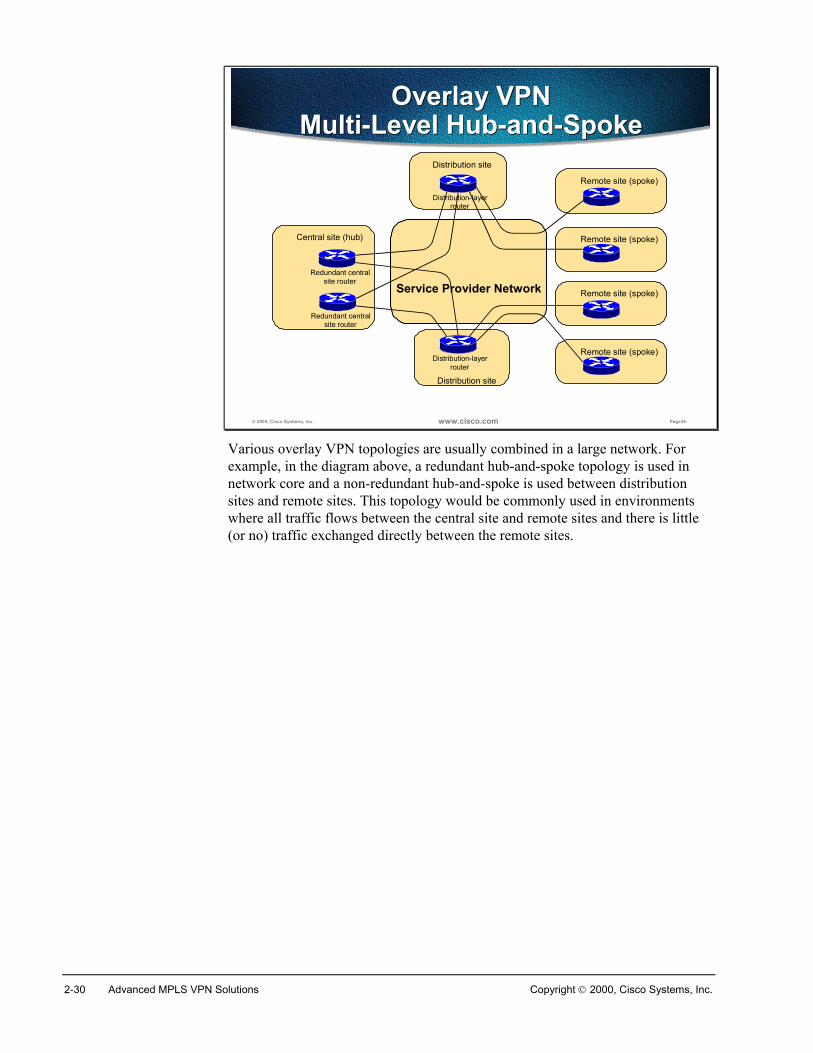
Various overlay VPN topologies are usually combined in a large network. Forexample, in the diagram above, a redundant hub-and-spoke topology is used innetwork core and a non-redundant hub-and-spoke is used between distributionsites and remote sites. This topology would be commonly used in environmentswhere all traffic flows between the central site and remote sites and there is little(or no) traffic exchanged directly between the remote sites.
Copyright 2000, Cisco Systems, Inc. MPLS VPN Technology 2-31
© 2000, Cisco Systems, Inc. www.cisco.com Page37
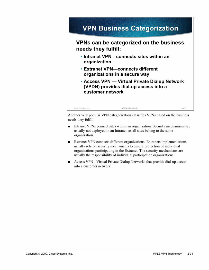
VPN Business CategorizationVPN Business Categorization
VPNs can be categorized on the business needs they fulfill:
• Intranet VPN—connects sites within an organization
• Extranet VPN—connects different organizations in a secure way
• Access VPN — Virtual Private Dialup Network (VPDN) provides dial-up access into a customer network
Another very popular VPN categorization classifies VPNs based on the businessneeds they fulfill:
� Intranet VPNs connect sites within an organization. Security mechanisms areusually not deployed in an Intranet, as all sites belong to the sameorganization.
� Extranet VPN connects different organizations. Extranets implementationsusually rely on security mechanisms to ensure protection of individualorganizations participating in the Extranet. The security mechanisms areusually the responsibility of individual participation organizations.
� Access VPN - Virtual Private Dialup Networks that provide dial-up accessinto a customer network.
2-32 Advanced MPLS VPN Solutions Copyright 2000, Cisco Systems, Inc.
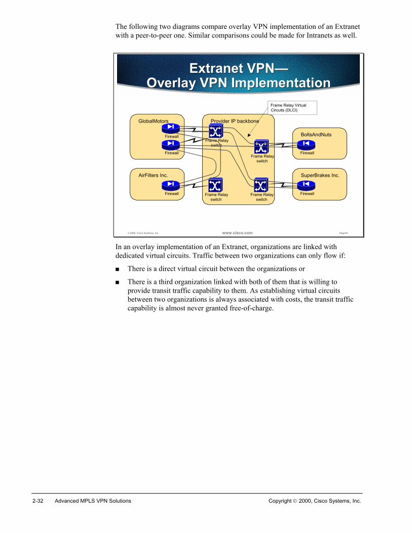
The following two diagrams compare overlay VPN implementation of an Extranetwith a peer-to-peer one. Similar comparisons could be made for Intranets as well.
© 2000, Cisco Systems, Inc. www.cisco.com Page38
Extranet VPN—Overlay VPN Implementation
Extranet VPN—Overlay VPN Implementation
Provider IP backboneGlobalMotors
Firewall
AirFilters Inc.
Firewall
BoltsAndNuts
Firewall
SuperBrakes Inc.
Firewall
FirewallFrame Relay
switch
Frame Relayswitch
Frame Relayswitch
Frame Relayswitch
Frame Relay VirtualCircuits (DLCI)
In an overlay implementation of an Extranet, organizations are linked withdedicated virtual circuits. Traffic between two organizations can only flow if:
� There is a direct virtual circuit between the organizations or
� There is a third organization linked with both of them that is willing toprovide transit traffic capability to them. As establishing virtual circuitsbetween two organizations is always associated with costs, the transit trafficcapability is almost never granted free-of-charge.
Copyright 2000, Cisco Systems, Inc. MPLS VPN Technology 2-33
© 2000, Cisco Systems, Inc. www.cisco.com Page39
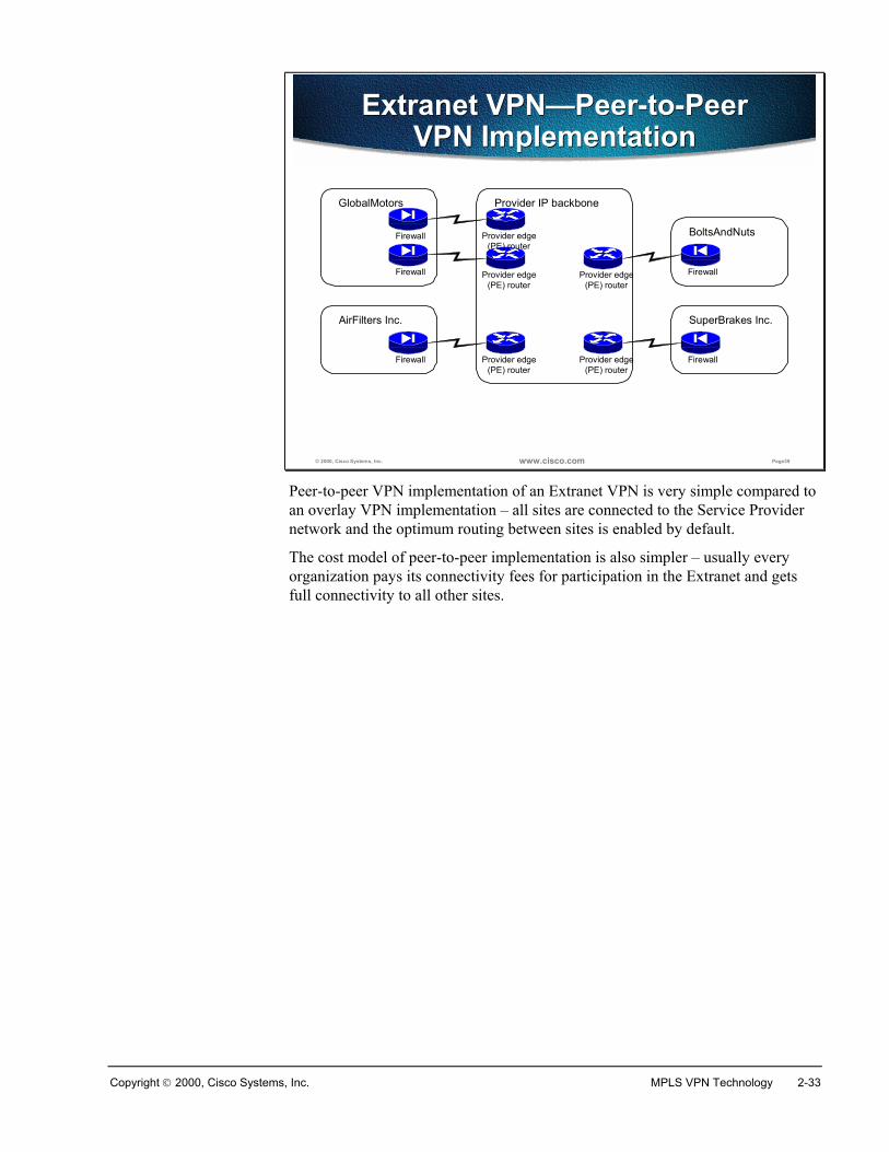
Extranet VPN—Peer-to-Peer VPN Implementation
Extranet VPN—Peer-to-Peer VPN Implementation
Provider IP backboneGlobalMotors
Firewall
AirFilters Inc.
Firewall
BoltsAndNuts
Firewall
SuperBrakes Inc.
Firewall
Provider edge(PE) router
Provider edge(PE) router
Provider edge(PE) router
Provider edge(PE) router
Firewall Provider edge(PE) router
Peer-to-peer VPN implementation of an Extranet VPN is very simple compared toan overlay VPN implementation – all sites are connected to the Service Providernetwork and the optimum routing between sites is enabled by default.
The cost model of peer-to-peer implementation is also simpler – usually everyorganization pays its connectivity fees for participation in the Extranet and getsfull connectivity to all other sites.
2-34 Advanced MPLS VPN Solutions Copyright 2000, Cisco Systems, Inc.
© 2000, Cisco Systems, Inc. www.cisco.com Page40
VPN Connectivity Categorization
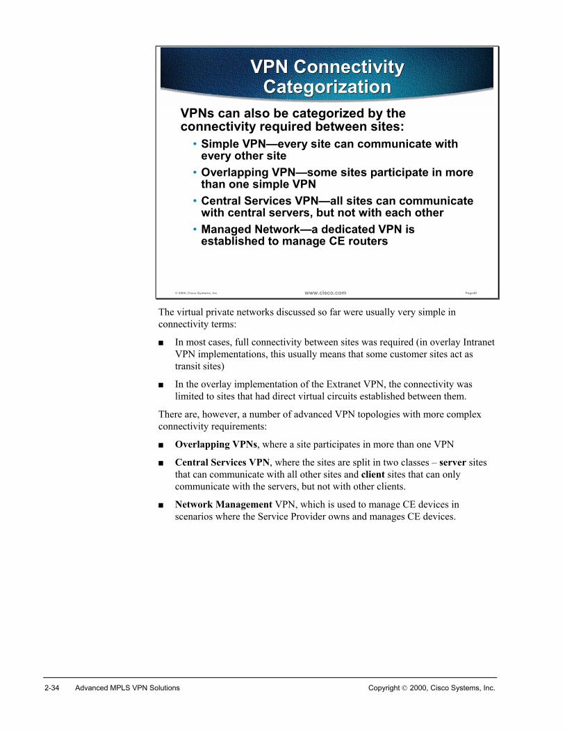
VPN Connectivity Categorization
VPNs can also be categorized by the connectivity required between sites:
• Simple VPN—every site can communicate with every other site
• Overlapping VPN—some sites participate in more than one simple VPN
• Central Services VPN—all sites can communicate with central servers, but not with each other
• Managed Network—a dedicated VPN is established to manage CE routers
The virtual private networks discussed so far were usually very simple inconnectivity terms:
� In most cases, full connectivity between sites was required (in overlay IntranetVPN implementations, this usually means that some customer sites act astransit sites)
� In the overlay implementation of the Extranet VPN, the connectivity waslimited to sites that had direct virtual circuits established between them.
There are, however, a number of advanced VPN topologies with more complexconnectivity requirements:
� Overlapping VPNs, where a site participates in more than one VPN
� Central Services VPN, where the sites are split in two classes – server sitesthat can communicate with all other sites and client sites that can onlycommunicate with the servers, but not with other clients.
� Network Management VPN, which is used to manage CE devices inscenarios where the Service Provider owns and manages CE devices.
Copyright 2000, Cisco Systems, Inc. MPLS VPN Technology 2-35
© 2000, Cisco Systems, Inc. www.cisco.com Page41
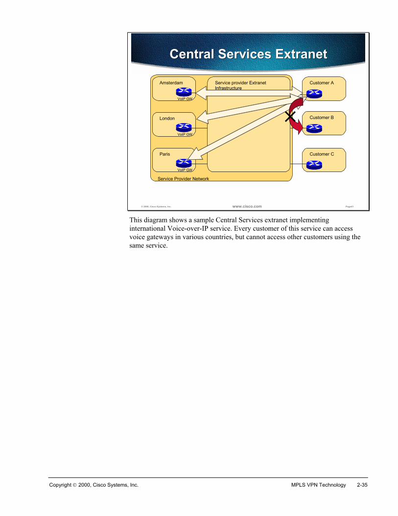
Central Services ExtranetCentral Services Extranet
Service Provider Network
Service provider ExtranetInfrastructure
London
VoIP GW
Amsterdam
VoIP GW
Paris
VoIP GW
Customer A
Customer B
Customer C
This diagram shows a sample Central Services extranet implementinginternational Voice-over-IP service. Every customer of this service can accessvoice gateways in various countries, but cannot access other customers using thesame service.
2-36 Advanced MPLS VPN Solutions Copyright 2000, Cisco Systems, Inc.
© 2000, Cisco Systems, Inc. www.cisco.com Page42
Central Services Extranet—Hybrid (Overlay + P2P) Implementation
Central Services Extranet—Hybrid (Overlay + P2P) Implementation
Service Provider Network
Service providerExtranet Infrastructure
London
VoIP GW
Amsterdam
VoIP GW
Paris
VoIP GW
Customer A
Customer B
Customer C
FrameRelayInfrastructure
Frame RelayEdge switch
Frame RelayEdge switch
Frame RelayEdge switch
Provider EdgeRouter
Frame Relay Virtual Circuit
Provider EdgeRouter
Provider EdgeRouter
Provider EdgeRouter
Provider EdgeRouter
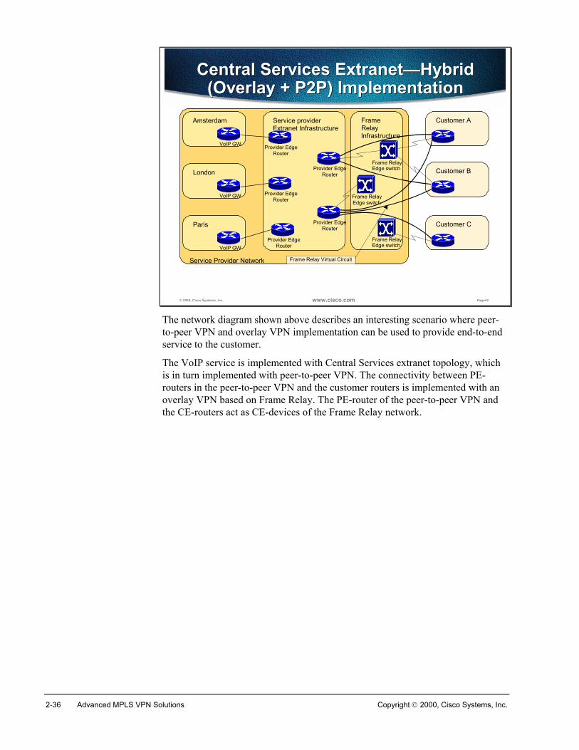
The network diagram shown above describes an interesting scenario where peer-to-peer VPN and overlay VPN implementation can be used to provide end-to-endservice to the customer.
The VoIP service is implemented with Central Services extranet topology, whichis in turn implemented with peer-to-peer VPN. The connectivity between PE-routers in the peer-to-peer VPN and the customer routers is implemented with anoverlay VPN based on Frame Relay. The PE-router of the peer-to-peer VPN andthe CE-routers act as CE-devices of the Frame Relay network.
Copyright 2000, Cisco Systems, Inc. MPLS VPN Technology 2-37
© 2000, Cisco Systems, Inc. www.cisco.com Page43
Managed NetworkOverlay VPN Implementation
Managed NetworkOverlay VPN Implementation
Central site (hub)
Service provider network Remote site (spoke)
Remote site (spoke)
Remote site (spoke)
Redundant centralsite router
Redundant centralsite router
Network Management Center
Dedicated Virtual Circuits are used for network management
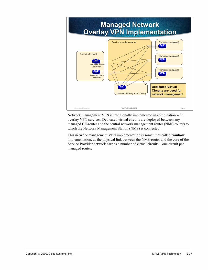
Network management VPN is traditionally implemented in combination withoverlay VPN services. Dedicated virtual circuits are deployed between anymanaged CE-router and the central network management router (NMS-router) towhich the Network Management Station (NMS) is connected.
This network management VPN implementation is sometimes called rainbowimplementation, as the physical link between the NMS-router and the core of theService Provider network carries a number of virtual circuits – one circuit permanaged router.
2-38 Advanced MPLS VPN Solutions Copyright 2000, Cisco Systems, Inc.
SummaryThere are three major categorizations of Virtual Private networks:
� Topology categorization, which classifies the VPNs based on the topology ofpoint-to-point connections in overlay VPN implementation
� Business categorization, which classifies VPNs into Intranets, Extranets andniche solutions like Virtual Private Dialup Networks
� Connectivity categorization, which classifies VPNs based on the connectivityneeds.
The topology categorization ranges VPNs from full mesh, where there is a directvirtual circuit between any two sites, to partial mesh, which is built based on anumber of constraints (traffic patterns and cost being the most important of them)and finally hub-and-spoke where a central site acts as the transit point between allspoke sites. Real-life large networks are usually implemented with a combinationof these topologies.
The connectivity categorization divides VPNs into simple VPNs (with any-to-anyconnectivity), overlay VPNs where a single site participates in more than onesimple VPN, Central Services VPNs, where some sites have limited connectivityand Network Management VPNs, which are really only a special case of CentralServices VPN.
Review QuestionsAnswer the following questions:
� What are the major Overlay VPN topologies
� Why would the customers prefer partial mesh over full mesh topology?
� What is the difference between an Intranet and an Extranet?
� What is the difference between a simple VPN and a Central Services VPN?
� What are the connectivity requirements of a Central Services VPN?
Copyright 2000, Cisco Systems, Inc. MPLS VPN Technology 2-39
MPLS VPN Architecture
ObjectivesUpon completion of this section, you will be able to perform the following tasks:
� Understand the difference between traditional peer-to-peer models and MPLSVPN
� List the benefits of MPLS VPN
� Describe major architectural blocks of MPLS VPN
� Explain the need for route distinguisher (RD) and route target (RT)
2-40 Advanced MPLS VPN Solutions Copyright 2000, Cisco Systems, Inc.
© 2000, Cisco Systems, Inc. www.cisco.com Page48
MPLS VPN ArchitectureMPLS VPN Architecture
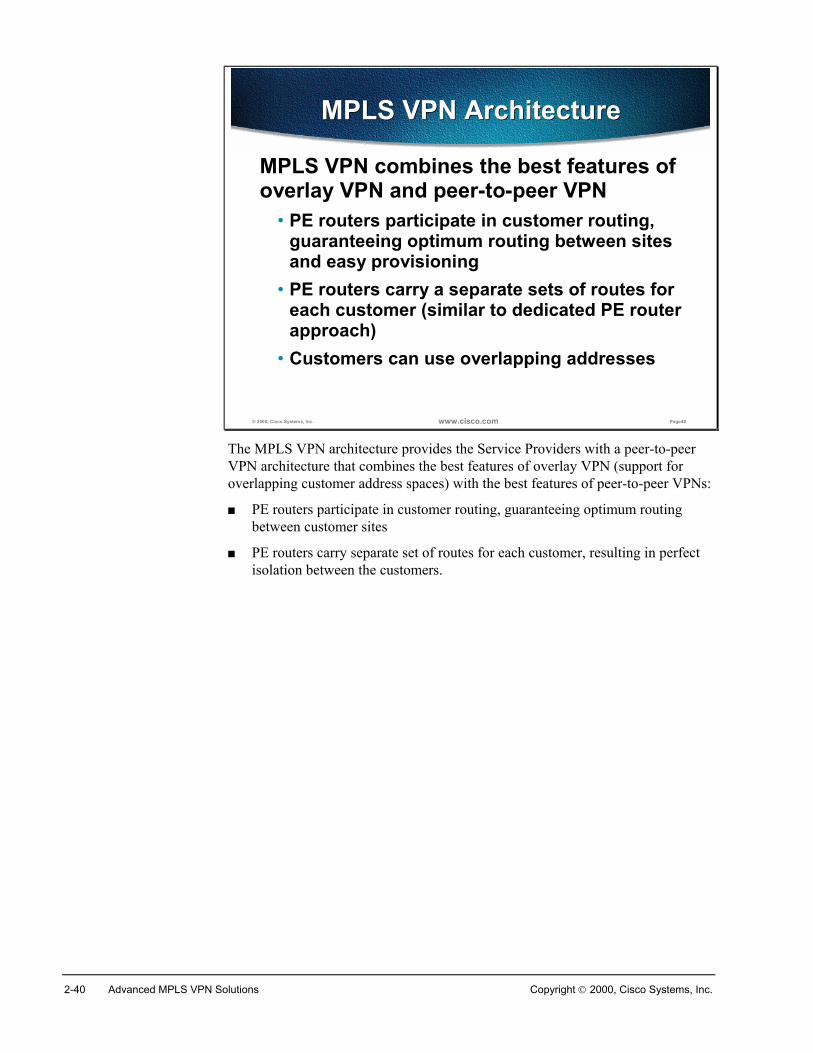
MPLS VPN combines the best features of overlay VPN and peer-to-peer VPN
• PE routers participate in customer routing, guaranteeing optimum routing between sites and easy provisioning
• PE routers carry a separate sets of routes for each customer (similar to dedicated PE router approach)
• Customers can use overlapping addresses
The MPLS VPN architecture provides the Service Providers with a peer-to-peerVPN architecture that combines the best features of overlay VPN (support foroverlapping customer address spaces) with the best features of peer-to-peer VPNs:
� PE routers participate in customer routing, guaranteeing optimum routingbetween customer sites
� PE routers carry separate set of routes for each customer, resulting in perfectisolation between the customers.
Copyright 2000, Cisco Systems, Inc. MPLS VPN Technology 2-41
© 2000, Cisco Systems, Inc. www.cisco.com Page49
MPLS VPN TerminologyMPLS VPN Terminology
Customer ASite #1
Site #1CE router
Customer ASite #2
Customer BSite #1
Customer BSite #3
Customer BSite #2
Customer ASite #4
RemoteOffice
RemoteOffice
Customer ASite #3
Customer BSite #4
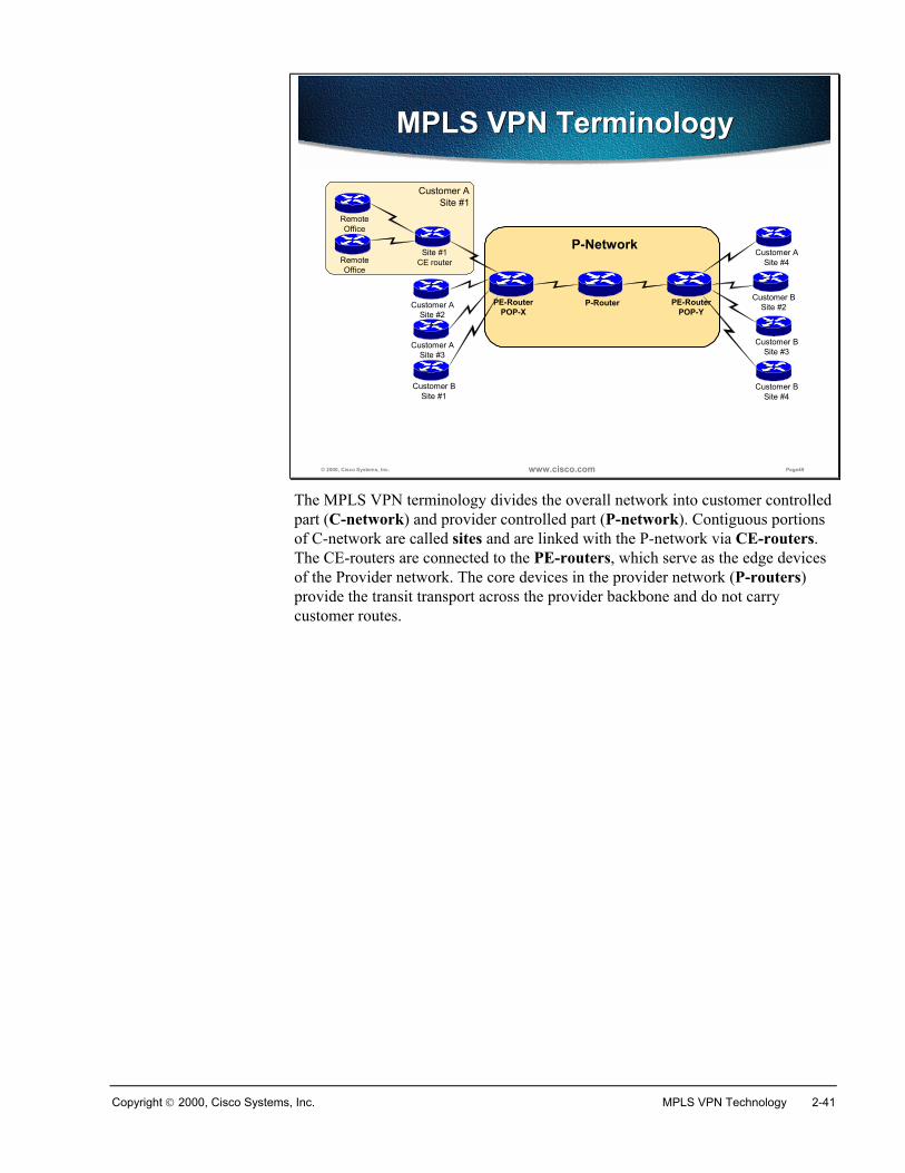
PE-RouterPOP-X
P-Router PE-RouterPOP-Y
P-Network
The MPLS VPN terminology divides the overall network into customer controlledpart (C-network) and provider controlled part (P-network). Contiguous portionsof C-network are called sites and are linked with the P-network via CE-routers.The CE-routers are connected to the PE-routers, which serve as the edge devicesof the Provider network. The core devices in the provider network (P-routers)provide the transit transport across the provider backbone and do not carrycustomer routes.
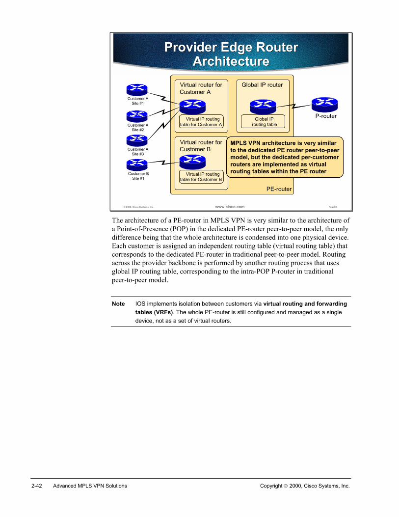
2-42 Advanced MPLS VPN Solutions Copyright 2000, Cisco Systems, Inc.
© 2000, Cisco Systems, Inc. www.cisco.com Page50
Provider Edge Router Architecture
Provider Edge Router Architecture
PE-router
Global IP router
Virtual router forCustomer B
Virtual router forCustomer A
P-router
Customer ASite #1
Customer ASite #2
Customer BSite #1
Virtual IP routingtable for Customer A
Virtual IP routingtable for Customer B
Global IProuting table
Customer ASite #3
MPLS VPN architecture is very similarto the dedicated PE router peer-to-peermodel, but the dedicated per-customerrouters are implemented as virtualrouting tables within the PE router
The architecture of a PE-router in MPLS VPN is very similar to the architecture ofa Point-of-Presence (POP) in the dedicated PE-router peer-to-peer model, the onlydifference being that the whole architecture is condensed into one physical device.Each customer is assigned an independent routing table (virtual routing table) thatcorresponds to the dedicated PE-router in traditional peer-to-peer model. Routingacross the provider backbone is performed by another routing process that usesglobal IP routing table, corresponding to the intra-POP P-router in traditionalpeer-to-peer model.
Note IOS implements isolation between customers via virtual routing and forwardingtables (VRFs). The whole PE-router is still configured and managed as a singledevice, not as a set of virtual routers.
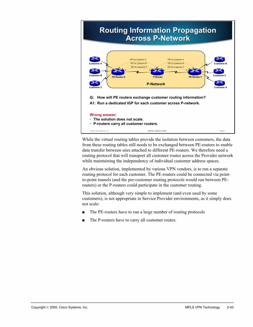
Copyright 2000, Cisco Systems, Inc. MPLS VPN Technology 2-43
© 2000, Cisco Systems, Inc. www.cisco.com Page51
P-Network
P-Router
Customer A
Customer B
Customer A
Customer C
Customer B
PE-Router-X PE-Router-Y
Customer C
Routing Information Propagation Across P-Network
Routing Information Propagation Across P-Network
Q: How will PE routers exchange customer routing information?
IGP for Customer C
IGP for Customer B
IGP for Customer A
IGP for Customer C
IGP for Customer B
IGP for Customer A
A1: Run a dedicated IGP for each customer across P-network.
Wrong answer:• The solution does not scale.• P-routers carry all customer routers.
While the virtual routing tables provide the isolation between customers, the datafrom these routing tables still needs to be exchanged between PE-routers to enabledata transfer between sites attached to different PE-routers. We therefore need arouting protocol that will transport all customer routes across the Provider networkwhile maintaining the independency of individual customer address spaces.
An obvious solution, implemented by various VPN vendors, is to run a separaterouting protocol for each customer. The PE-routers could be connected via point-to-point tunnels (and the per-customer routing protocols would run between PE-routers) or the P-routers could participate in the customer routing.
This solution, although very simple to implement (and even used by somecustomers), is not appropriate in Service Provider environments, as it simply doesnot scale:
� The PE-routers have to run a large number of routing protocols
� The P-routers have to carry all customer routes.
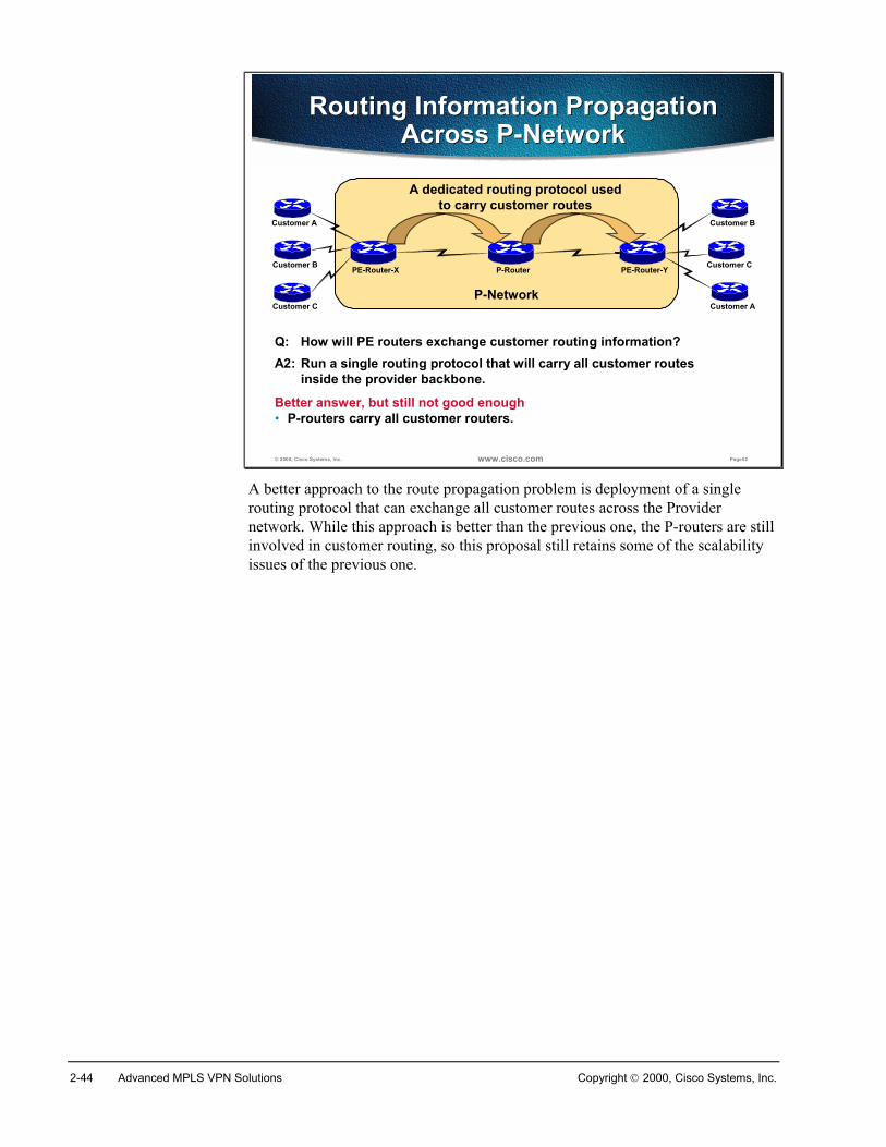
2-44 Advanced MPLS VPN Solutions Copyright 2000, Cisco Systems, Inc.
© 2000, Cisco Systems, Inc. www.cisco.com Page52
P-Network
P-Router
Customer A
Customer B
Customer A
Customer C
Customer B
PE-Router-X PE-Router-Y
Customer C
Routing Information Propagation Across P-Network
Routing Information Propagation Across P-Network
Q: How will PE routers exchange customer routing information?
Better answer, but still not good enough• P-routers carry all customer routers.
A2: Run a single routing protocol that will carry all customer routesinside the provider backbone.
A dedicated routing protocol usedto carry customer routes
A better approach to the route propagation problem is deployment of a singlerouting protocol that can exchange all customer routes across the Providernetwork. While this approach is better than the previous one, the P-routers are stillinvolved in customer routing, so this proposal still retains some of the scalabilityissues of the previous one.
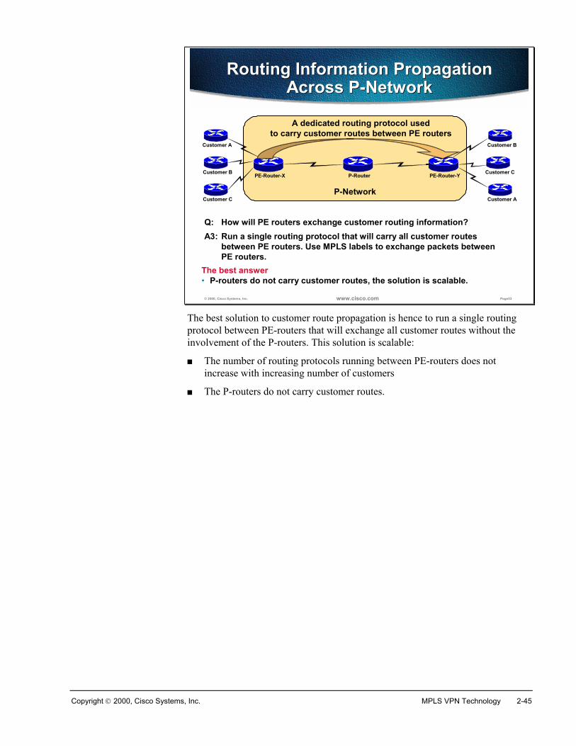
Copyright 2000, Cisco Systems, Inc. MPLS VPN Technology 2-45
© 2000, Cisco Systems, Inc. www.cisco.com Page53
P-Network
A dedicated routing protocol usedto carry customer routes between PE routers
P-Router
Customer A
Customer B
Customer A
Customer C
Customer B
PE-Router-X PE-Router-Y
Customer C
Routing Information Propagation Across P-Network
Routing Information Propagation Across P-Network
Q: How will PE routers exchange customer routing information?
The best answer• P-routers do not carry customer routes, the solution is scalable.
A3: Run a single routing protocol that will carry all customer routesbetween PE routers. Use MPLS labels to exchange packets betweenPE routers.
The best solution to customer route propagation is hence to run a single routingprotocol between PE-routers that will exchange all customer routes without theinvolvement of the P-routers. This solution is scalable:
� The number of routing protocols running between PE-routers does notincrease with increasing number of customers
� The P-routers do not carry customer routes.
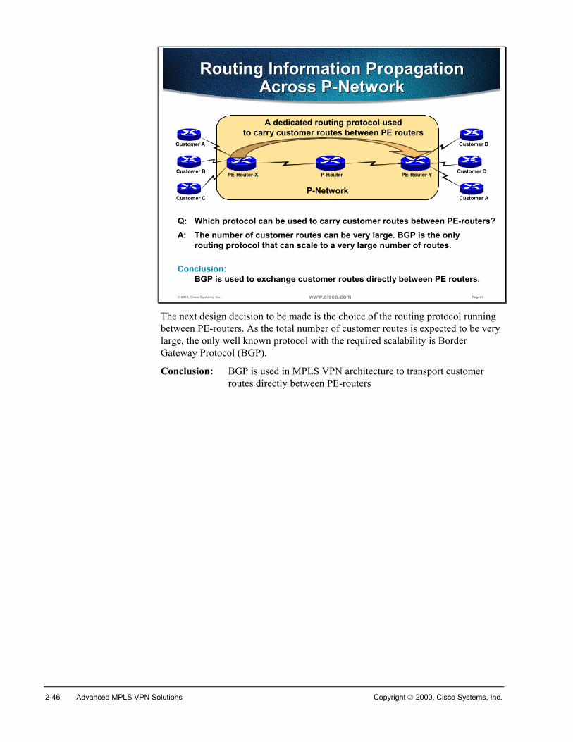
2-46 Advanced MPLS VPN Solutions Copyright 2000, Cisco Systems, Inc.
© 2000, Cisco Systems, Inc. www.cisco.com Page54
P-Network
A dedicated routing protocol usedto carry customer routes between PE routers
P-Router
Customer A
Customer B
Customer A
Customer C
Customer B
PE-Router-X PE-Router-Y
Customer C
Routing Information Propagation Across P-Network
Routing Information Propagation Across P-Network
Q: Which protocol can be used to carry customer routes between PE-routers?A: The number of customer routes can be very large. BGP is the only
routing protocol that can scale to a very large number of routes.
Conclusion:BGP is used to exchange customer routes directly between PE routers.
The next design decision to be made is the choice of the routing protocol runningbetween PE-routers. As the total number of customer routes is expected to be verylarge, the only well known protocol with the required scalability is BorderGateway Protocol (BGP).
Conclusion: BGP is used in MPLS VPN architecture to transport customerroutes directly between PE-routers
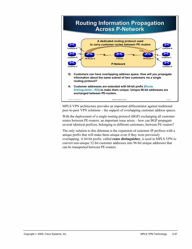
Copyright 2000, Cisco Systems, Inc. MPLS VPN Technology 2-47
© 2000, Cisco Systems, Inc. www.cisco.com Page55
P-Network
A dedicated routing protocol usedto carry customer routes between PE routers
P-Router
Customer A
Customer B
Customer A
Customer C
Customer B
PE-Router-X PE-Router-Y
Customer C
Routing Information Propagation Across P-Network
Routing Information Propagation Across P-Network
Q: Customers can have overlapping address space. How will you propagateinformation about the same subnet of two customers via a singlerouting protocol?
A: Customer addresses are extended with 64-bit prefix (Route Distinguisher—RD) to make them unique. Unique 96-bit addresses areexchanged between PE-routers.
MPLS VPN architecture provides an important differentiator against traditionalpeer-to-peer VPN solutions – the support of overlapping customer address spaces.
With the deployment of a single routing protocol (BGP) exchanging all customerroutes between PE-routers, an important issue arises – how can BGP propagateseveral identical prefixes, belonging to different customers, between PE-routers?
The only solution to this dilemma is the expansion of customer IP prefixes with aunique prefix that will make them unique even if they were previouslyoverlapping. A 64-bit prefix, called route distinguisher, is used in MPLS VPN toconvert non-unique 32-bit customer addresses into 96-bit unique addresses thatcan be transported between PE-routers.
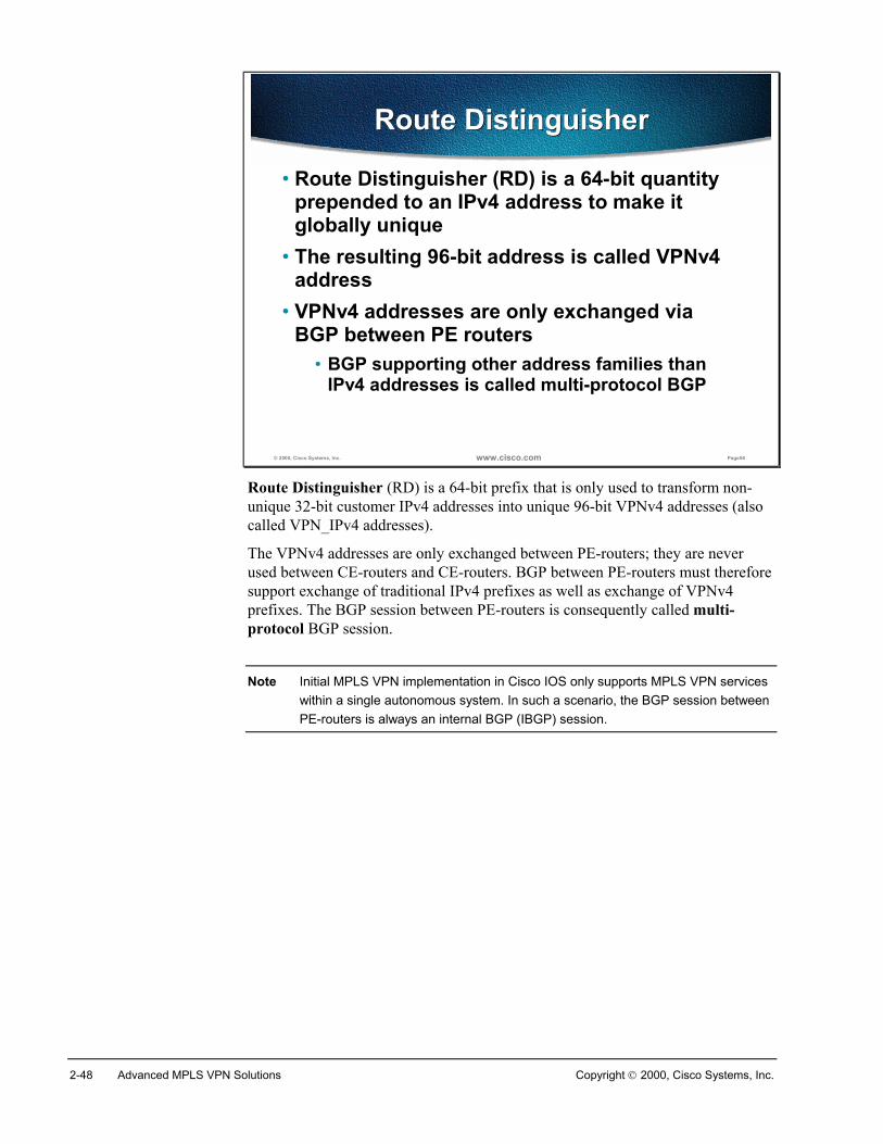
2-48 Advanced MPLS VPN Solutions Copyright 2000, Cisco Systems, Inc.
© 2000, Cisco Systems, Inc. www.cisco.com Page56
Route DistinguisherRoute Distinguisher
• Route Distinguisher (RD) is a 64-bit quantity prepended to an IPv4 address to make it globally unique
• The resulting 96-bit address is called VPNv4 address
• VPNv4 addresses are only exchanged via BGP between PE routers
• BGP supporting other address families than IPv4 addresses is called multi-protocol BGP
Route Distinguisher (RD) is a 64-bit prefix that is only used to transform non-unique 32-bit customer IPv4 addresses into unique 96-bit VPNv4 addresses (alsocalled VPN_IPv4 addresses).
The VPNv4 addresses are only exchanged between PE-routers; they are neverused between CE-routers and CE-routers. BGP between PE-routers must thereforesupport exchange of traditional IPv4 prefixes as well as exchange of VPNv4prefixes. The BGP session between PE-routers is consequently called multi-protocol BGP session.
Note Initial MPLS VPN implementation in Cisco IOS only supports MPLS VPN serviceswithin a single autonomous system. In such a scenario, the BGP session betweenPE-routers is always an internal BGP (IBGP) session.
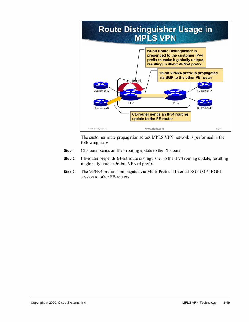
Copyright 2000, Cisco Systems, Inc. MPLS VPN Technology 2-49
© 2000, Cisco Systems, Inc. www.cisco.com Page57
Route Distinguisher Usage in MPLS VPN
Route Distinguisher Usage in MPLS VPN
P-network
PE-1 PE-2
Customer-A
Customer-B
Customer-A
Customer-B
CE-router sends an IPv4 routing update to the PE-router
64-bit Route Distinguisher is prepended to the customer IPv4 prefix to make it globally unique, resulting in 96-bit VPNv4 prefix
96-bit VPNv4 prefix is propagated via BGP to the other PE router
The customer route propagation across MPLS VPN network is performed in thefollowing steps:
Step 1 CE-router sends an IPv4 routing update to the PE-router
Step 2 PE-router prepends 64-bit route distinguisher to the IPv4 routing update, resultingin globally unique 96-bin VPNv4 prefix
Step 3 The VPNv4 prefix is propagated via Multi-Protocol Internal BGP (MP-IBGP)session to other PE-routers
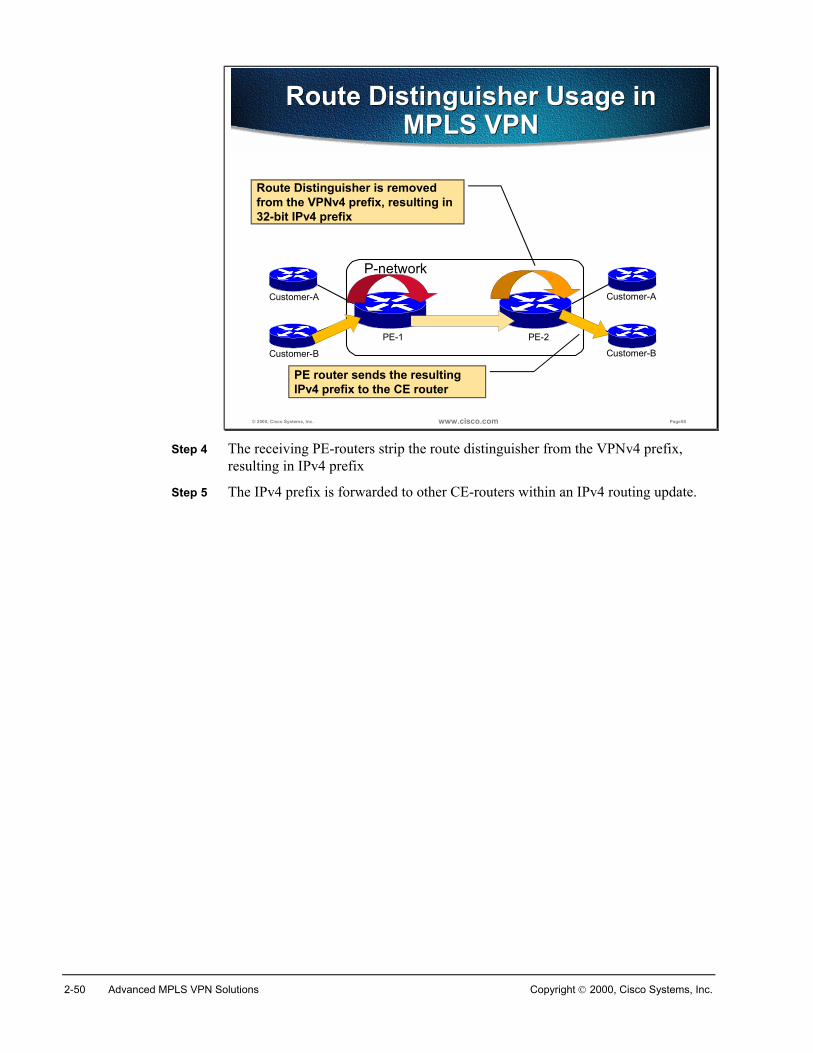
2-50 Advanced MPLS VPN Solutions Copyright 2000, Cisco Systems, Inc.
© 2000, Cisco Systems, Inc. www.cisco.com Page58
Route Distinguisher Usage in MPLS VPN
Route Distinguisher Usage in MPLS VPN
P-network
PE-1 PE-2
Customer-A
Customer-B
Customer-A
Customer-B
PE router sends the resulting IPv4 prefix to the CE router
Route Distinguisher is removed from the VPNv4 prefix, resulting in 32-bit IPv4 prefix
Step 4 The receiving PE-routers strip the route distinguisher from the VPNv4 prefix,resulting in IPv4 prefix
Step 5 The IPv4 prefix is forwarded to other CE-routers within an IPv4 routing update.
Copyright 2000, Cisco Systems, Inc. MPLS VPN Technology 2-51
© 2000, Cisco Systems, Inc. www.cisco.com Page59
Route Distinguisher Usage in MPLS VPN
Route Distinguisher Usage in MPLS VPN
• RD has no special meaning—it is only used to make potentially overlapping IPv4 addresses globally unique
• Simple VPN topologies require one RD per customer
• RD could serve as VPN identifier for simple VPN topologies, but this design could not support all topologies required by the customers
The route distinguisher has no special meaning or role in MPLS VPN architecture– its only function is to make overlapping IPv4 addresses globally unique.
Note As there has to be a unique one-to-one mapping between the route distinguishersand virtual routing and forwarding tables, the route distinguisher could be viewedas the VRF identifier in Cisco’s implementation of MPLS VPN.
The route distinguisher is configured at the PE router as part of the setup of a VPNsite. It is not configured on the customer equipment, and is not visible to thecustomer.
Simple VPN topologies only require one route distinguisher per customer, raisingthe possibility that RD could serve as VPN identifier. This design, however,would not allow implementation of more complex VPN topologies, like when acustomer site belongs to multiple VPNs.
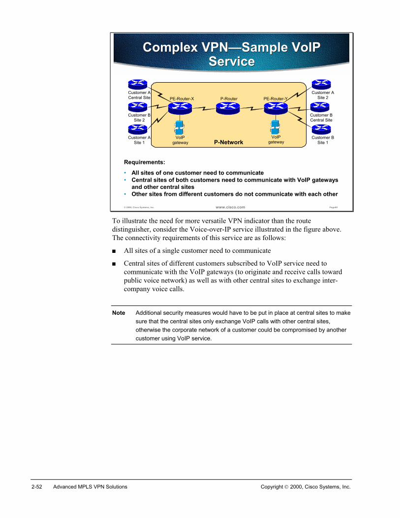
2-52 Advanced MPLS VPN Solutions Copyright 2000, Cisco Systems, Inc.
© 2000, Cisco Systems, Inc. www.cisco.com Page60
P-Network
Complex VPN—Sample VoIP Service
Complex VPN—Sample VoIP Service
Requirements:
• All sites of one customer need to communicate• Central sites of both customers need to communicate with VoIP gateways
and other central sites• Other sites from different customers do not communicate with each other
Customer ACentral Site
Customer BSite 2
Customer BSite 1
Customer BCentral Site
Customer ASite 2
VoIPgateway
VoIPgateway
Customer ASite 1
PE-Router-X P-Router PE-Router-Y
To illustrate the need for more versatile VPN indicator than the routedistinguisher, consider the Voice-over-IP service illustrated in the figure above.The connectivity requirements of this service are as follows:
� All sites of a single customer need to communicate
� Central sites of different customers subscribed to VoIP service need tocommunicate with the VoIP gateways (to originate and receive calls towardpublic voice network) as well as with other central sites to exchange inter-company voice calls.
Note Additional security measures would have to be put in place at central sites to makesure that the central sites only exchange VoIP calls with other central sites,otherwise the corporate network of a customer could be compromised by anothercustomer using VoIP service.
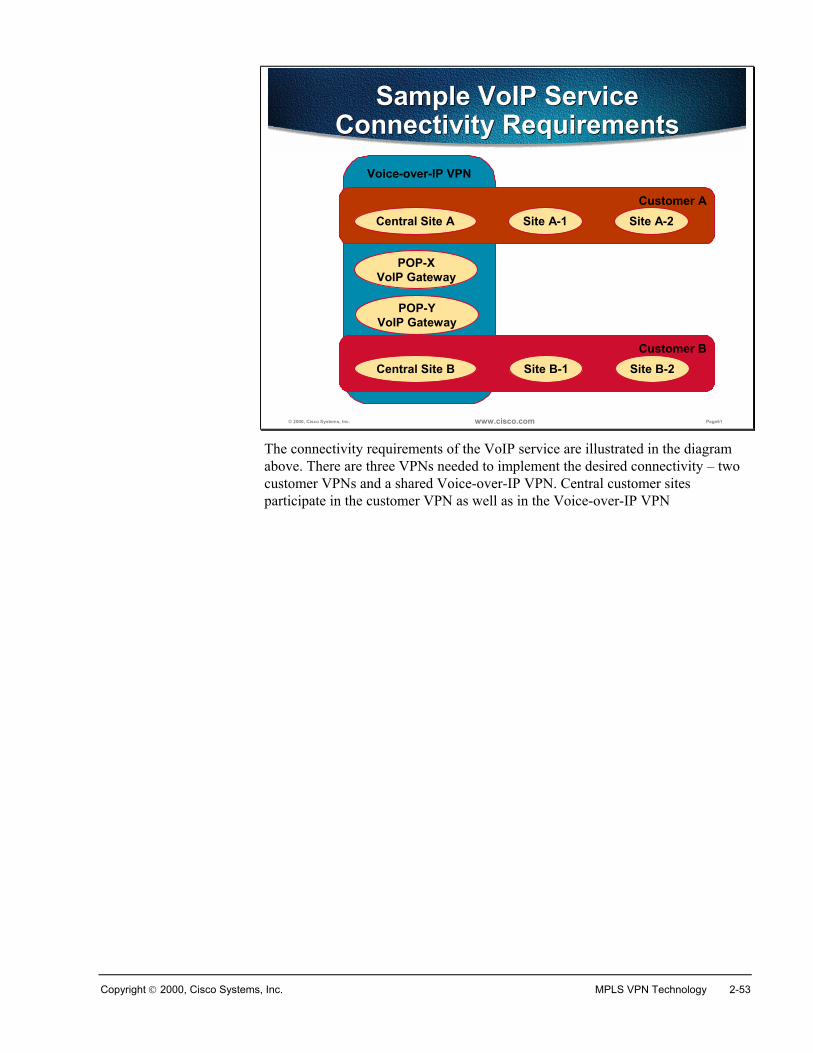
Copyright 2000, Cisco Systems, Inc. MPLS VPN Technology 2-53
© 2000, Cisco Systems, Inc. www.cisco.com Page61
Voice-over-IP VPN
Sample VoIP ServiceConnectivity Requirements
Sample VoIP ServiceConnectivity Requirements
Customer A
Customer B
Central Site A Site A-1 Site A-2
Central Site B Site B-1 Site B-2
POP-XVoIP Gateway
POP-YVoIP Gateway
The connectivity requirements of the VoIP service are illustrated in the diagramabove. There are three VPNs needed to implement the desired connectivity – twocustomer VPNs and a shared Voice-over-IP VPN. Central customer sitesparticipate in the customer VPN as well as in the Voice-over-IP VPN
2-54 Advanced MPLS VPN Solutions Copyright 2000, Cisco Systems, Inc.
© 2000, Cisco Systems, Inc. www.cisco.com Page62
Route TargetsRoute Targets
• Some sites have to participate in more than one VPN—route distinguisher cannot identify participation in VPN
• A different method is needed where a set of identifiers can be attached to a route
• Route Targets were introduced in the MPLS VPN architecture to support complex VPN topologies
The route distinguisher (which is a single entity prepended to an IPv4 route)cannot indicate that a site participates in more than one VPN. A different methodis needed where a set of VPN identifiers could be attached to a route to indicate itsmembership in several VPNs.
The route targets were introduced in the MPLS VPN architecture to support thisrequirement.
Copyright 2000, Cisco Systems, Inc. MPLS VPN Technology 2-55
© 2000, Cisco Systems, Inc. www.cisco.com Page63
What are Route Targets?What are Route Targets?
• Route Targets are additional attributes attached to VPNv4 BGP routes to indicate VPN membership
• Extended BGP communities are used to encode these attributes• Extended communities carry the meaning of
the attribute together with its value• Any number of route targets can be attached to a single route
Route targets are extended BGP communities that are attached to a VPNv4 BGProute to indicate its VPN membership. As with standard BGP communities, a setof extended communities can be attached to a single BGP route, satisfying therequirements of complex VPN topologies.
Extended BGP communities are 64-bit values. The semantics of the extended BGPcommunity is encoded in the high-order 16 bits of the value, making them usefulfor a number of different applications. For example, the value of high-order 16bits of extended BGP community is two (2) for MPLS VPN Route Targets.
2-56 Advanced MPLS VPN Solutions Copyright 2000, Cisco Systems, Inc.
© 2000, Cisco Systems, Inc. www.cisco.com Page64
How do Route Targets Work?How do Route Targets Work?
• Export route targets identifying VPN membership are appended to customer route when it is converted into VPNv4 route
• Each virtual routing table has a set of associated import route targets that select routes to be inserted into the virtual routing table
• Route targets usually identify VPN membership, but can also be used in more complex scenarios
MPLS VPN route targets are attached to a customer route at the moment when it’sconverted from IPv4 route to a VPNv4 route by the PE-router. The route targetsattached to the route are called export route target and are configured separatelyfor each virtual routing table in a PE-router. The export route targets identify a setof VPNs in which sites associated with the virtual routing table belong.
When the VPNv4 routes are propagated to other PE-routers, those routers need toselect the routes to import into their virtual routing tables. This selection is donebased on import route targets. Each virtual routing table in a PE-router can havea number of import route targets configured, identifying the set of VPNs fromwhich this virtual routing table is accepting routes.
Note Please refer to MPLS VPN Implementation on Cisco IOS chapter for moredetails on import and export route targets.
In overlapping VPN topologies, the route targets are used to identify VPNmembership. Advanced VPN topologies (for example, central services VPN) useroute targets in more complex scenarios – please refer to MPLS VPN Topologieschapter of MPLS VPN Solutions lesson for more details.
Copyright 2000, Cisco Systems, Inc. MPLS VPN Technology 2-57
© 2000, Cisco Systems, Inc. www.cisco.com Page65
Virtual Private Networks Redefined
Virtual Private Networks Redefined
With the support of complex VPN topologies, the VPNs have to be redefined
• A VPN is a collection of sites sharing common routing information
• A site can be part of different VPNs• A VPN can be seen as a community of interest
(Closed User Group—CUG)• Complex VPN topologies are supported by
multiple virtual routing tables on the PE routers
With the introduction of complex VPN topologies, the definition of a VirtualPrivate Network needs to be changed – a VPN is simply a collection of sitessharing common routing information. In traditional switched WAN terms (forexample, in X.25 terminology), such a concept would be called closed user group(CUG).
A site can be part of different VPNs, resulting in differing routing requirementsfor sites that belong to different sets of VPNs. These routing requirements have tobe supported with multiple virtual routing tables on the PE-routers.
2-58 Advanced MPLS VPN Solutions Copyright 2000, Cisco Systems, Inc.
© 2000, Cisco Systems, Inc. www.cisco.com Page66
Impact of Complex VPN Topologies on Virtual Routing Tables
Impact of Complex VPN Topologies on Virtual Routing Tables
• A virtual routing table in a PE router can only be used for sites with identical connectivity requirements
• Complex VPN topologies require more than one virtual routing table per VPN
• As each virtual routing table requires a distinct RD value, the number of RDs in the MPLS VPN network increases
A single virtual routing table can only be used for sites with identical connectivityrequirements. Complex VPN topologies therefore require more than one virtualrouting table per VPN.
Note If you would associate sites with different requirements with the same virtualrouting table, some of them might be able to access destinations that should notbe accessible to them otherwise.
As each virtual routing table requires a distinctive route distinguisher value, thenumber of route distinguisher in MPLS VPN network increases with theintroduction of overlapping VPNs. Moreover, the simple association betweenroute distinguisher and VPN that was true for simple VPNs is also gone.
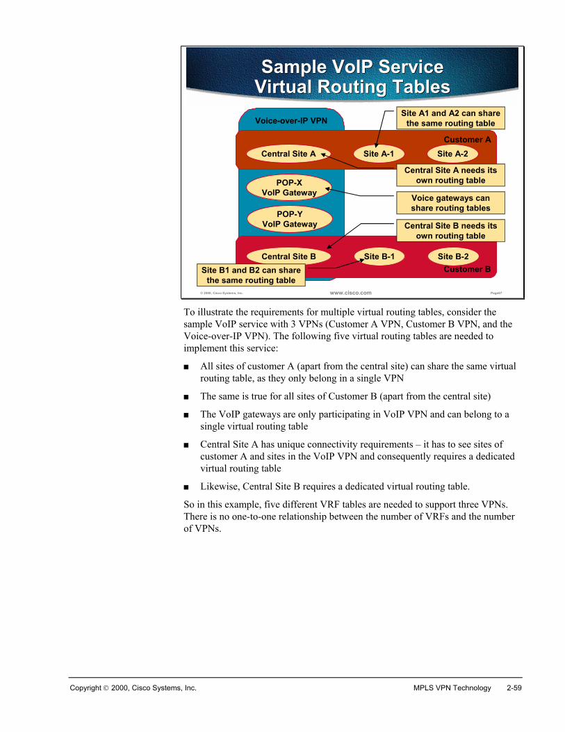
Copyright 2000, Cisco Systems, Inc. MPLS VPN Technology 2-59
© 2000, Cisco Systems, Inc. www.cisco.com Page67
Voice-over-IP VPN
Sample VoIP ServiceVirtual Routing TablesSample VoIP Service
Virtual Routing Tables
Customer A
Customer B
Central Site A Site A-1 Site A-2
Central Site B Site B-1 Site B-2
POP-XVoIP Gateway
POP-YVoIP Gateway
Central Site A needs its own routing table
Central Site B needs its own routing table
Site A1 and A2 can share the same routing table
Voice gateways can share routing tables
Site B1 and B2 can share the same routing table
To illustrate the requirements for multiple virtual routing tables, consider thesample VoIP service with 3 VPNs (Customer A VPN, Customer B VPN, and theVoice-over-IP VPN). The following five virtual routing tables are needed toimplement this service:
� All sites of customer A (apart from the central site) can share the same virtualrouting table, as they only belong in a single VPN
� The same is true for all sites of Customer B (apart from the central site)
� The VoIP gateways are only participating in VoIP VPN and can belong to asingle virtual routing table
� Central Site A has unique connectivity requirements – it has to see sites ofcustomer A and sites in the VoIP VPN and consequently requires a dedicatedvirtual routing table
� Likewise, Central Site B requires a dedicated virtual routing table.
So in this example, five different VRF tables are needed to support three VPNs.There is no one-to-one relationship between the number of VRFs and the numberof VPNs.
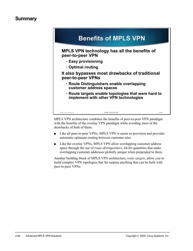
2-60 Advanced MPLS VPN Solutions Copyright 2000, Cisco Systems, Inc.
Summary
© 2000, Cisco Systems, Inc. www.cisco.com Page68
Benefits of MPLS VPNBenefits of MPLS VPN
MPLS VPN technology has all the benefits of peer-to-peer VPN
• Easy provisioning• Optimal routing
It also bypasses most drawbacks of traditional peer-to-peer VPNs
• Route Distinguishers enable overlapping customer address spaces
• Route targets enable topologies that were hard to implement with other VPN technologies
MPLS VPN architecture combines the benefits of peer-to-peer VPN paradigmwith the benefits of the overlay VPN paradigm while avoiding most of thedrawbacks of both of them:
� Like all peer-to-peer VPNs, MPLS VPN is easier to provision and providesautomatic optimum routing between customer sites
� Like the overlay VPNs, MPLS VPN allow overlapping customer addressspace through the use of route distinguishers, 64-bit quantities that makeoverlapping customer addresses globally unique when prepended to them.
Another building block of MPLS VPN architecture, route targets, allow you tobuild complex VPN topologies that far surpass anything that can be built withpeer-to-peer VPNs.
Copyright 2000, Cisco Systems, Inc. MPLS VPN Technology 2-61
Review QuestionsAnswer the following questions:
� How does MPLS VPN support overlapping customer address spaces?
� How are customer routes exchanged across the P-network?
� What is a route distinguisher?
� Why is the RD not usable as VPN identifier?
� Why were the route targets introduced in MPLS VPN architecture
� What is a route target?
� How are route targets used to build virtual routing tables in the PE routers?
� What is the impact of complex VPN topologies on virtual routing tables in thePE routers?
2-62 Advanced MPLS VPN Solutions Copyright 2000, Cisco Systems, Inc.
MPLS VPN Routing Model
ObjectivesUpon completion of this section, you will be able to perform the following tasks:
� Understand the routing model of MPLS VPN
� Describe the MPLS VPN routing model from customer and providerperspective
� Identify the routing requirements of CE-routers, PE-routers and P-routers
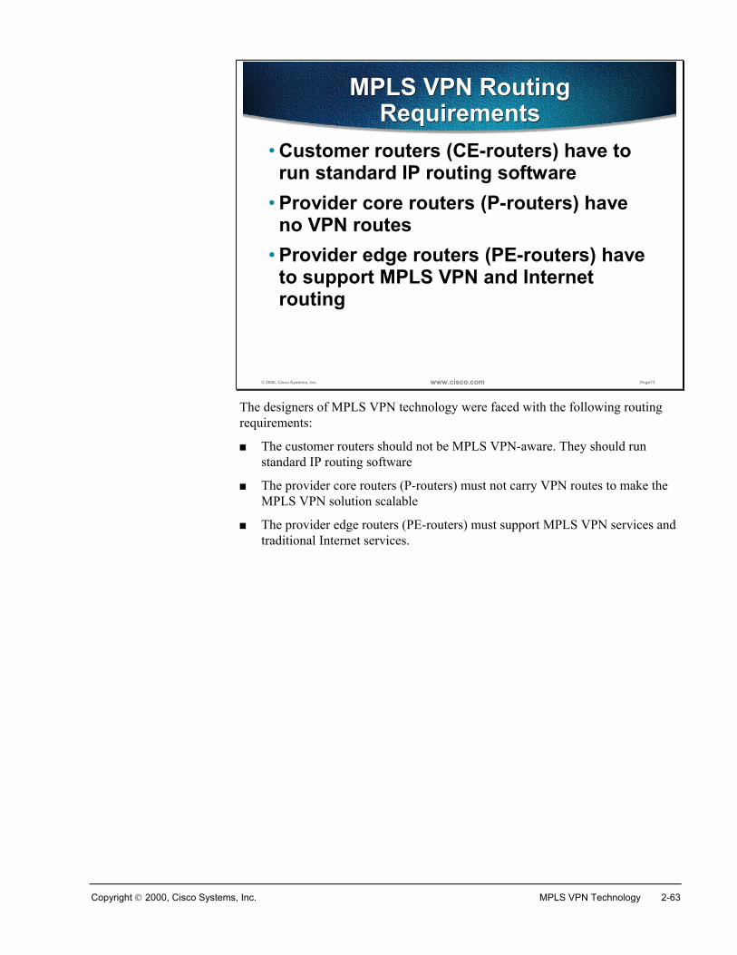
Copyright 2000, Cisco Systems, Inc. MPLS VPN Technology 2-63
© 2000, Cisco Systems, Inc. www.cisco.com Page73
MPLS VPN Routing Requirements
MPLS VPN Routing Requirements
• Customer routers (CE-routers) have to run standard IP routing software
• Provider core routers (P-routers) have no VPN routes
• Provider edge routers (PE-routers) have to support MPLS VPN and Internet routing
The designers of MPLS VPN technology were faced with the following routingrequirements:
� The customer routers should not be MPLS VPN-aware. They should runstandard IP routing software
� The provider core routers (P-routers) must not carry VPN routes to make theMPLS VPN solution scalable
� The provider edge routers (PE-routers) must support MPLS VPN services andtraditional Internet services.
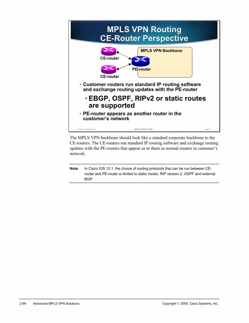
2-64 Advanced MPLS VPN Solutions Copyright 2000, Cisco Systems, Inc.
© 2000, Cisco Systems, Inc. www.cisco.com Page74
MPLS VPN RoutingCE-Router Perspective
MPLS VPN RoutingCE-Router Perspective
• Customer routers run standard IP routing software and exchange routing updates with the PE-router
• EBGP, OSPF, RIPv2 or static routes are supported
• PE-router appears as another router in the customer’s network
MPLS VPN Backbone
PE-router
CE-router
CE-router
The MPLS VPN backbone should look like a standard corporate backbone to theCE-routers. The CE-routers run standard IP routing software and exchange routingupdates with the PE-routers that appear as to them as normal routers in customer’snetwork.
Note In Cisco IOS 12.1, the choice of routing protocols that can be run between CE-router and PE-router is limited to static routes, RIP version 2, OSPF and externalBGP.
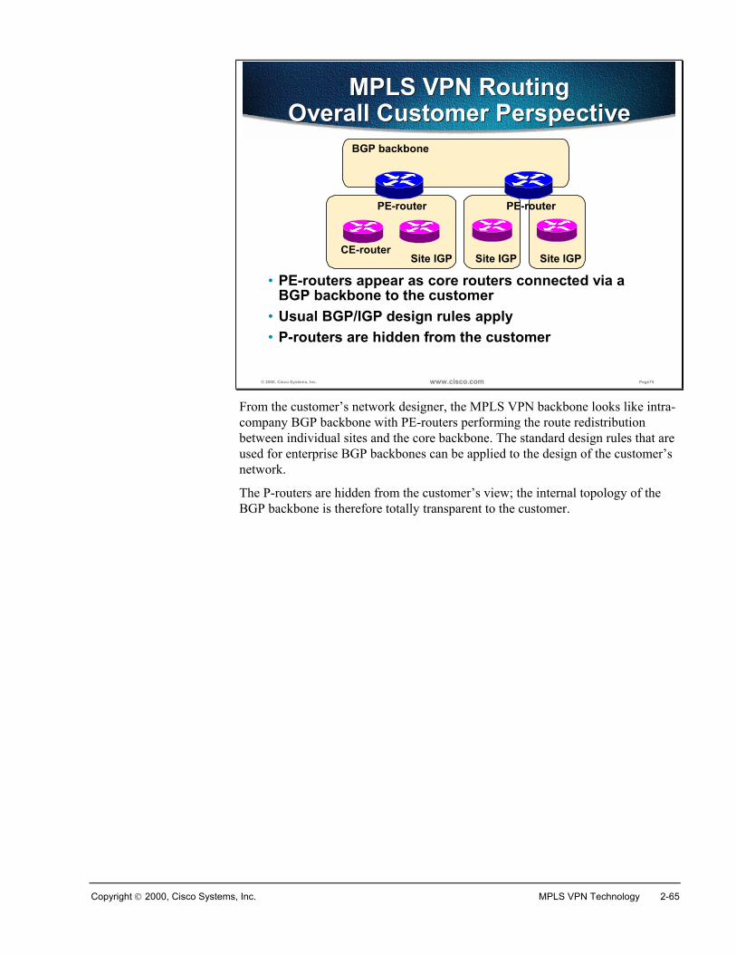
Copyright 2000, Cisco Systems, Inc. MPLS VPN Technology 2-65
© 2000, Cisco Systems, Inc. www.cisco.com Page75
MPLS VPN RoutingOverall Customer Perspective
MPLS VPN RoutingOverall Customer Perspective
• PE-routers appear as core routers connected via a BGP backbone to the customer
• Usual BGP/IGP design rules apply• P-routers are hidden from the customer
Site IGP
BGP backbone
CE-router
PE-router
Site IGP Site IGP
PE-router
From the customer’s network designer, the MPLS VPN backbone looks like intra-company BGP backbone with PE-routers performing the route redistributionbetween individual sites and the core backbone. The standard design rules that areused for enterprise BGP backbones can be applied to the design of the customer’snetwork.
The P-routers are hidden from the customer’s view; the internal topology of theBGP backbone is therefore totally transparent to the customer.
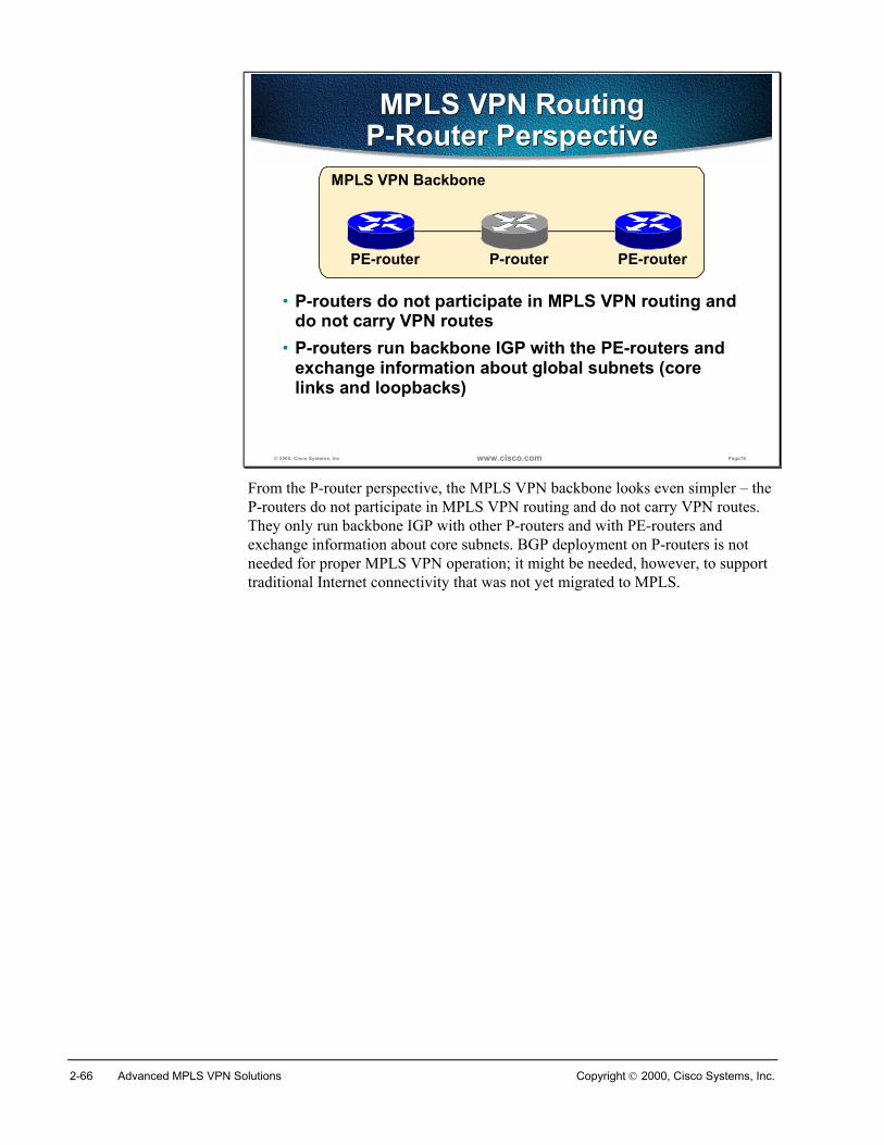
2-66 Advanced MPLS VPN Solutions Copyright 2000, Cisco Systems, Inc.
© 2000, Cisco Systems, Inc. www.cisco.com Page76
MPLS VPN RoutingP-Router PerspectiveMPLS VPN Routing
P-Router Perspective
• P-routers do not participate in MPLS VPN routing and do not carry VPN routes
• P-routers run backbone IGP with the PE-routers and exchange information about global subnets (core links and loopbacks)
MPLS VPN Backbone
P-routerPE-router PE-router
From the P-router perspective, the MPLS VPN backbone looks even simpler – theP-routers do not participate in MPLS VPN routing and do not carry VPN routes.They only run backbone IGP with other P-routers and with PE-routers andexchange information about core subnets. BGP deployment on P-routers is notneeded for proper MPLS VPN operation; it might be needed, however, to supporttraditional Internet connectivity that was not yet migrated to MPLS.
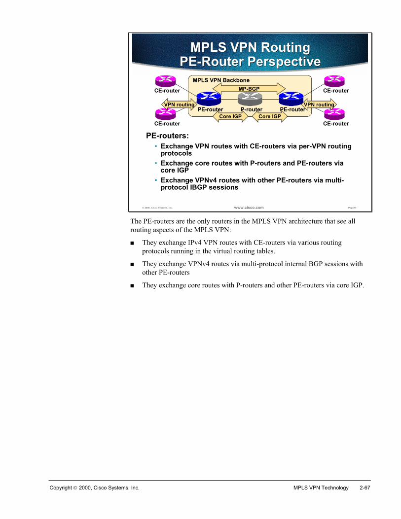
Copyright 2000, Cisco Systems, Inc. MPLS VPN Technology 2-67
© 2000, Cisco Systems, Inc. www.cisco.com Page77
MPLS VPN RoutingPE-Router Perspective
MPLS VPN RoutingPE-Router Perspective
PE-routers:• Exchange VPN routes with CE-routers via per-VPN routing
protocols• Exchange core routes with P-routers and PE-routers via
core IGP• Exchange VPNv4 routes with other PE-routers via multi-
protocol IBGP sessions
MPLS VPN Backbone
P-routerPE-router PE-router
CE-router
CE-router
CE-router
CE-router
MP-BGP
Core IGP Core IGP
VPN routing VPN routing
The PE-routers are the only routers in the MPLS VPN architecture that see allrouting aspects of the MPLS VPN:
� They exchange IPv4 VPN routes with CE-routers via various routingprotocols running in the virtual routing tables.
� They exchange VPNv4 routes via multi-protocol internal BGP sessions withother PE-routers
� They exchange core routes with P-routers and other PE-routers via core IGP.
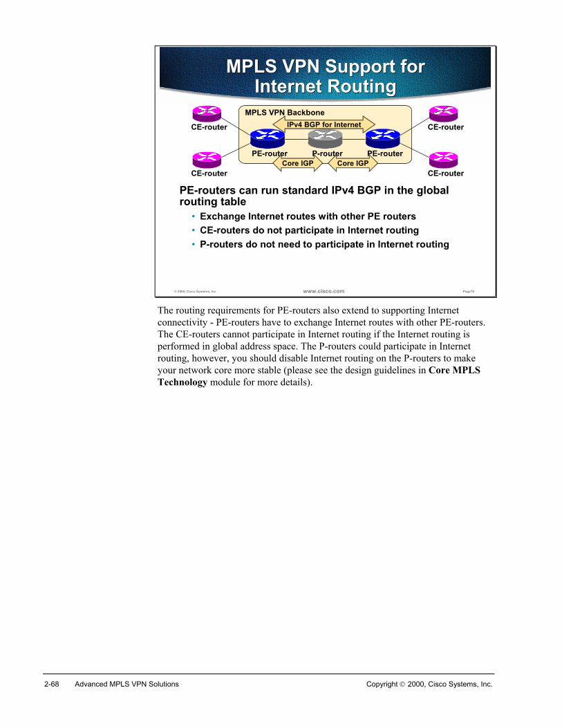
2-68 Advanced MPLS VPN Solutions Copyright 2000, Cisco Systems, Inc.
© 2000, Cisco Systems, Inc. www.cisco.com Page78
MPLS VPN Support for Internet Routing
MPLS VPN Support for Internet Routing
PE-routers can run standard IPv4 BGP in the global routing table
• Exchange Internet routes with other PE routers• CE-routers do not participate in Internet routing• P-routers do not need to participate in Internet routing
MPLS VPN Backbone
P-routerPE-router PE-router
CE-router
CE-router
CE-router
CE-router
IPv4 BGP for Internet
Core IGP Core IGP
The routing requirements for PE-routers also extend to supporting Internetconnectivity - PE-routers have to exchange Internet routes with other PE-routers.The CE-routers cannot participate in Internet routing if the Internet routing isperformed in global address space. The P-routers could participate in Internetrouting, however, you should disable Internet routing on the P-routers to makeyour network core more stable (please see the design guidelines in Core MPLSTechnology module for more details).
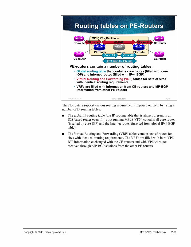
Copyright 2000, Cisco Systems, Inc. MPLS VPN Technology 2-69
© 2000, Cisco Systems, Inc. www.cisco.com Page79
Routing tables on PE-RoutersRouting tables on PE-Routers
PE-routers contain a number of routing tables:• Global routing table that contains core routes (filled with core
IGP) and Internet routes (filled with IPv4 BGP)• Virtual Routing and Forwarding (VRF) tables for sets of sites
with identical routing requirements• VRFs are filled with information from CE-routers and MP-BGP
information from other PE-routers
MPLS VPN Backbone
P-routerPE-router PE-router
CE-router
CE-router
CE-router
CE-router
MP-BGP
Core IGP Core IGP
VPN routing VPN routing
IPv4 BGP for Internet
The PE-routers support various routing requirements imposed on them by using anumber of IP routing tables:
� The global IP routing table (the IP routing table that is always present in anIOS-based router even if it’s not running MPLS VPN) contains all core routes(inserted by core IGP) and the Internet routes (inserted from global IPv4 BGPtable)
� The Virtual Routing and Forwarding (VRF) tables contain sets of routes forsites with identical routing requirements. The VRFs are filled with intra-VPNIGP information exchanged with the CE-routers and with VPNv4 routesreceived through MP-BGP sessions from the other PE-routers
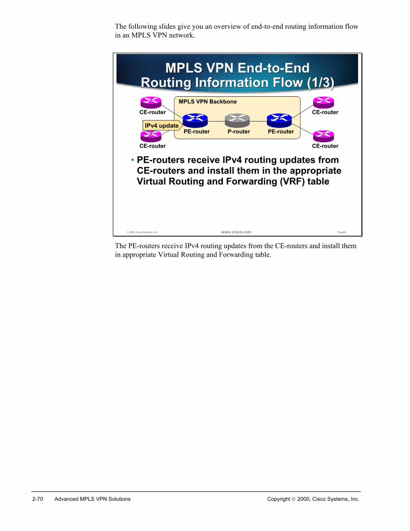
2-70 Advanced MPLS VPN Solutions Copyright 2000, Cisco Systems, Inc.
The following slides give you an overview of end-to-end routing information flowin an MPLS VPN network.
© 2000, Cisco Systems, Inc. www.cisco.com Page80
MPLS VPN End-to-End Routing Information Flow (1/3)
MPLS VPN End-to-End Routing Information Flow (1/3)
• PE-routers receive IPv4 routing updates from CE-routers and install them in the appropriate Virtual Routing and Forwarding (VRF) table
MPLS VPN Backbone
P-routerPE-router PE-router
CE-router
CE-router
CE-router
CE-router
IPv4 update
The PE-routers receive IPv4 routing updates from the CE-routers and install themin appropriate Virtual Routing and Forwarding table.
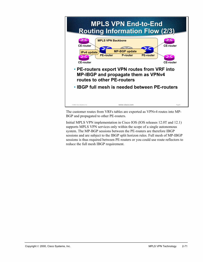
Copyright 2000, Cisco Systems, Inc. MPLS VPN Technology 2-71
© 2000, Cisco Systems, Inc. www.cisco.com Page81
MPLS VPN End-to-End Routing Information Flow (2/3)
MPLS VPN End-to-End Routing Information Flow (2/3)
• PE-routers export VPN routes from VRF into MP-IBGP and propagate them as VPNv4 routes to other PE-routers
• IBGP full mesh is needed between PE-routers
MPLS VPN Backbone
P-routerPE-router PE-router
CE-router
CE-router
CE-router
CE-router
MP-BGP updateIPv4 update
The customer routes from VRFs tables are exported as VPNv4 routes into MP-BGP and propagated to other PE-routers.
Initial MPLS VPN implementation in Cisco IOS (IOS releases 12.0T and 12.1)supports MPLS VPN services only within the scope of a single autonomoussystem. The MP-BGP sessions between the PE-routers are therefore IBGPsessions and are subject to the IBGP split horizon rules. Full mesh of MP-IBGPsessions is thus required between PE-routers or you could use route reflectors toreduce the full mesh IBGP requirement.
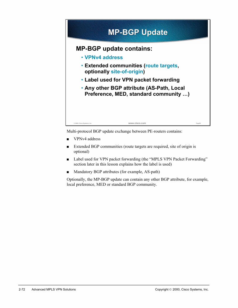
2-72 Advanced MPLS VPN Solutions Copyright 2000, Cisco Systems, Inc.
© 2000, Cisco Systems, Inc. www.cisco.com Page82
MP-BGP UpdateMP-BGP Update
MP-BGP update contains:• VPNv4 address• Extended communities (route targets,
optionally site-of-origin)• Label used for VPN packet forwarding• Any other BGP attribute (AS-Path, Local
Preference, MED, standard community …)
Multi-protocol BGP update exchange between PE-routers contains:
� VPNv4 address
� Extended BGP communities (route targets are required, site of origin isoptional)
� Label used for VPN packet forwarding (the “MPLS VPN Packet Forwarding”section later in this lesson explains how the label is used)
� Mandatory BGP attributes (for example, AS-path)
Optionally, the MP-BGP update can contain any other BGP attribute, for example,local preference, MED or standard BGP community.
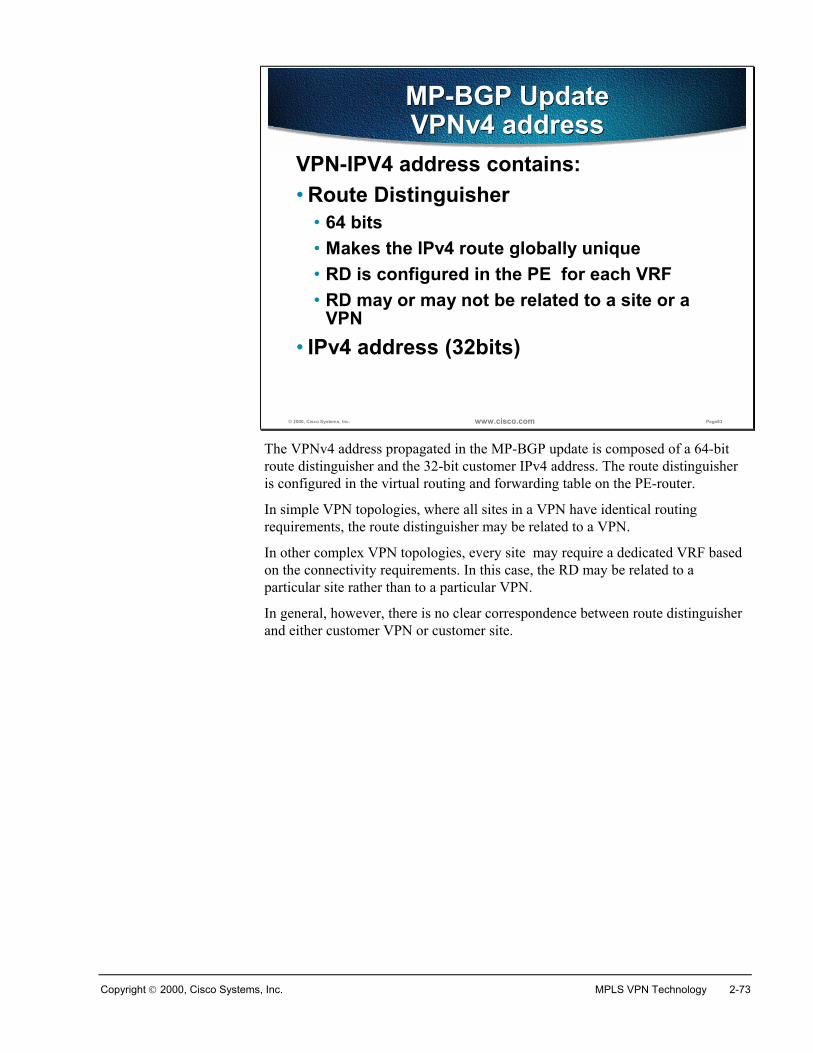
Copyright 2000, Cisco Systems, Inc. MPLS VPN Technology 2-73
© 2000, Cisco Systems, Inc. www.cisco.com Page83
MP-BGP UpdateVPNv4 addressMP-BGP UpdateVPNv4 address
VPN-IPV4 address contains:• Route Distinguisher
• 64 bits• Makes the IPv4 route globally unique • RD is configured in the PE for each VRF• RD may or may not be related to a site or a
VPN• IPv4 address (32bits)
The VPNv4 address propagated in the MP-BGP update is composed of a 64-bitroute distinguisher and the 32-bit customer IPv4 address. The route distinguisheris configured in the virtual routing and forwarding table on the PE-router.
In simple VPN topologies, where all sites in a VPN have identical routingrequirements, the route distinguisher may be related to a VPN.
In other complex VPN topologies, every site may require a dedicated VRF basedon the connectivity requirements. In this case, the RD may be related to aparticular site rather than to a particular VPN.
In general, however, there is no clear correspondence between route distinguisherand either customer VPN or customer site.
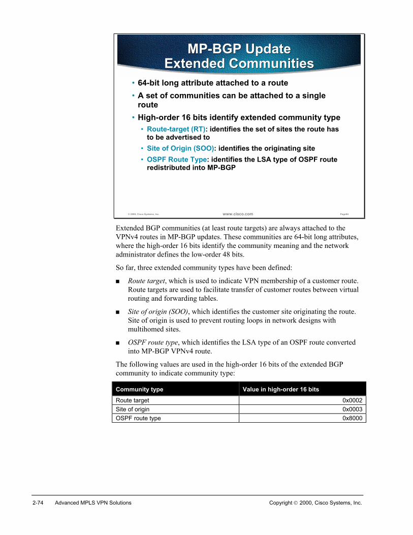
2-74 Advanced MPLS VPN Solutions Copyright 2000, Cisco Systems, Inc.
© 2000, Cisco Systems, Inc. www.cisco.com Page84
MP-BGP UpdateExtended Communities
MP-BGP UpdateExtended Communities
• 64-bit long attribute attached to a route• A set of communities can be attached to a single
route• High-order 16 bits identify extended community type
• Route-target (RT): identifies the set of sites the route has to be advertised to
• Site of Origin (SOO): identifies the originating site • OSPF Route Type: identifies the LSA type of OSPF route
redistributed into MP-BGP
Extended BGP communities (at least route targets) are always attached to theVPNv4 routes in MP-BGP updates. These communities are 64-bit long attributes,where the high-order 16 bits identify the community meaning and the networkadministrator defines the low-order 48 bits.
So far, three extended community types have been defined:
� Route target, which is used to indicate VPN membership of a customer route.Route targets are used to facilitate transfer of customer routes between virtualrouting and forwarding tables.
� Site of origin (SOO), which identifies the customer site originating the route.Site of origin is used to prevent routing loops in network designs withmultihomed sites.
� OSPF route type, which identifies the LSA type of an OSPF route convertedinto MP-BGP VPNv4 route.
The following values are used in the high-order 16 bits of the extended BGPcommunity to indicate community type:
Community type Value in high-order 16 bits
Route target 0x0002Site of origin 0x0003OSPF route type 0x8000
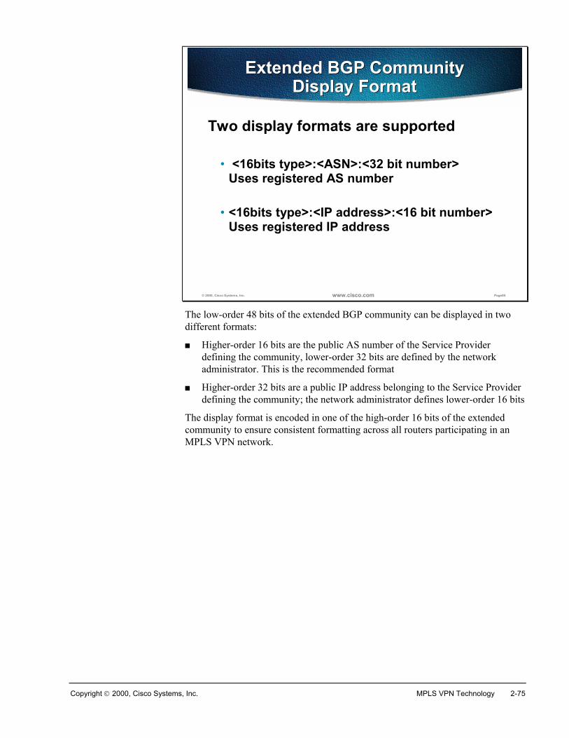
Copyright 2000, Cisco Systems, Inc. MPLS VPN Technology 2-75
© 2000, Cisco Systems, Inc. www.cisco.com Page85
Extended BGP Community Display Format
Extended BGP Community Display Format
Two display formats are supported
• <16bits type>:<ASN>:<32 bit number>Uses registered AS number
• <16bits type>:<IP address>:<16 bit number>Uses registered IP address
The low-order 48 bits of the extended BGP community can be displayed in twodifferent formats:
� Higher-order 16 bits are the public AS number of the Service Providerdefining the community, lower-order 32 bits are defined by the networkadministrator. This is the recommended format
� Higher-order 32 bits are a public IP address belonging to the Service Providerdefining the community; the network administrator defines lower-order 16 bits
The display format is encoded in one of the high-order 16 bits of the extendedcommunity to ensure consistent formatting across all routers participating in anMPLS VPN network.
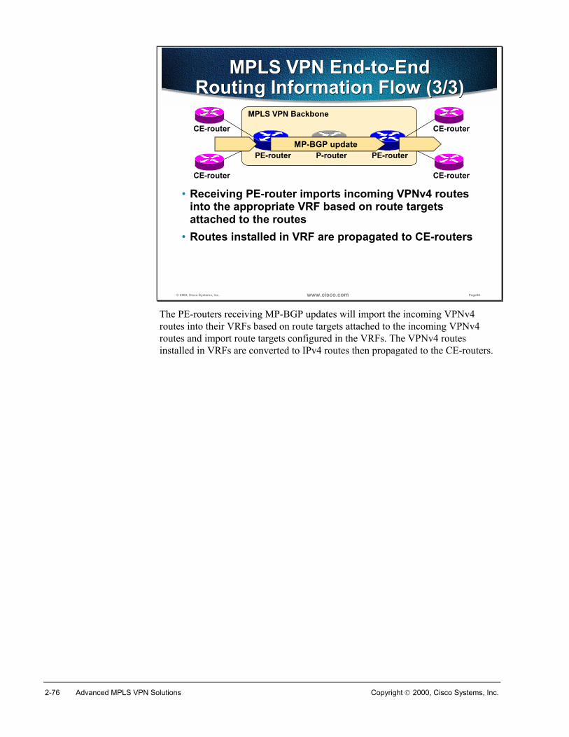
2-76 Advanced MPLS VPN Solutions Copyright 2000, Cisco Systems, Inc.
© 2000, Cisco Systems, Inc. www.cisco.com Page86
MPLS VPN End-to-End Routing Information Flow (3/3)
MPLS VPN End-to-End Routing Information Flow (3/3)
• Receiving PE-router imports incoming VPNv4 routes into the appropriate VRF based on route targets attached to the routes
• Routes installed in VRF are propagated to CE-routers
MPLS VPN Backbone
P-routerPE-router PE-router
CE-router
CE-router
CE-router
CE-router
MP-BGP update
The PE-routers receiving MP-BGP updates will import the incoming VPNv4routes into their VRFs based on route targets attached to the incoming VPNv4routes and import route targets configured in the VRFs. The VPNv4 routesinstalled in VRFs are converted to IPv4 routes then propagated to the CE-routers.
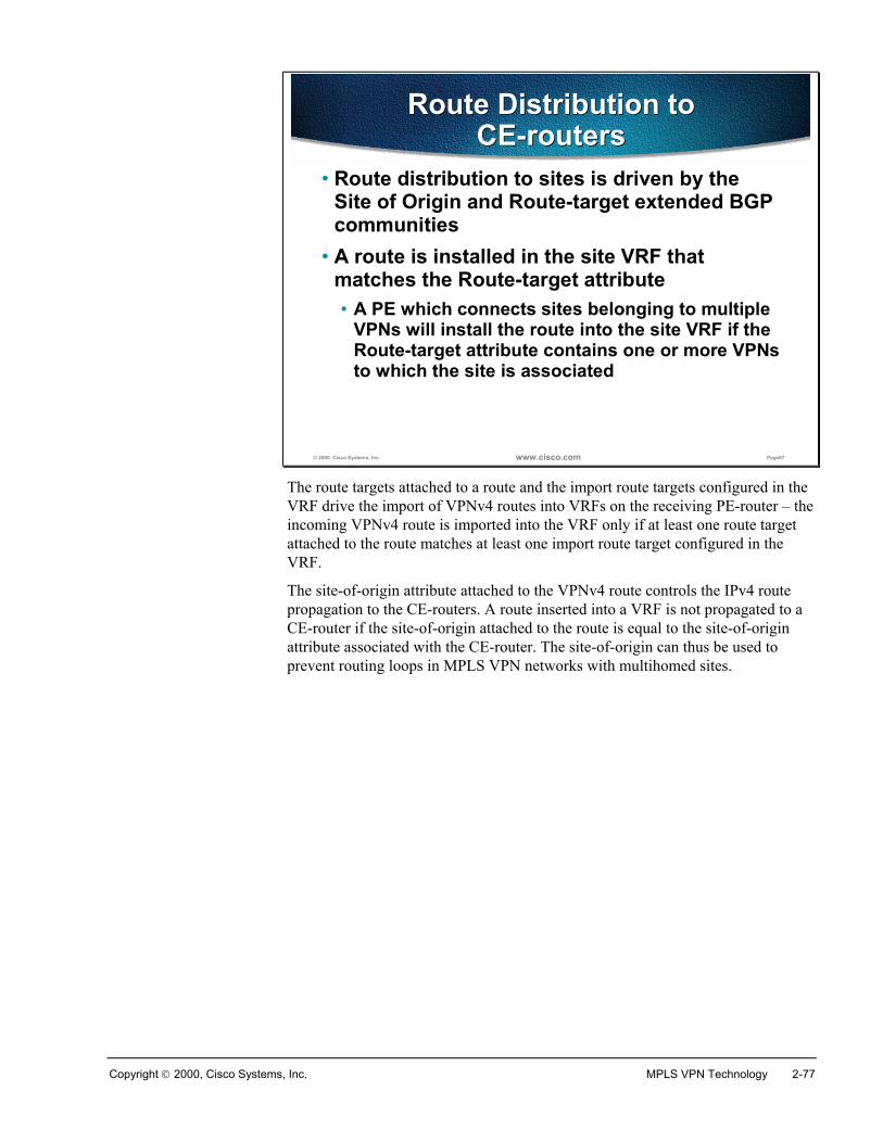
Copyright 2000, Cisco Systems, Inc. MPLS VPN Technology 2-77
© 2000, Cisco Systems, Inc. www.cisco.com Page87
Route Distribution to CE-routers
Route Distribution to CE-routers
• Route distribution to sites is driven by the Site of Origin and Route-target extended BGP communities
• A route is installed in the site VRF that matches the Route-target attribute• A PE which connects sites belonging to multiple
VPNs will install the route into the site VRF if the Route-target attribute contains one or more VPNsto which the site is associated
The route targets attached to a route and the import route targets configured in theVRF drive the import of VPNv4 routes into VRFs on the receiving PE-router – theincoming VPNv4 route is imported into the VRF only if at least one route targetattached to the route matches at least one import route target configured in theVRF.
The site-of-origin attribute attached to the VPNv4 route controls the IPv4 routepropagation to the CE-routers. A route inserted into a VRF is not propagated to aCE-router if the site-of-origin attached to the route is equal to the site-of-originattribute associated with the CE-router. The site-of-origin can thus be used toprevent routing loops in MPLS VPN networks with multihomed sites.
2-78 Advanced MPLS VPN Solutions Copyright 2000, Cisco Systems, Inc.
SummaryMPLS VPN routing model differs widely based on the perspective you take:
� The CE-routers do not see any difference between a private network and anetwork built with MPLS VPN technology
� The customer network designer perceives the MPLS VPN backbone as theBGP backbone of the enterprise network
� The P-routers do not see the customers or their VPN routing, they onlypropagate subnets of the MPLS backbone
� The PE-routers, however, run a variety of routing protocols with the VPNcustomers, propagate customer routes via MP-BGP updates to other PE-routers and at the same time participate in core IGP and Internet routing.
These differences in perspective satisfy the routing requirements of an MPLSVPN solution:
� The CE-routers shall run standard IP software and shall not be MPLS VPN-aware
� The P-routers shall not be MPLS VPN-aware and shall not carry customerroutes
� The PE-routers shall support core IGP and Internet routing together with theMPLS VPN service.
Review QuestionsAnswer the following questions:
� What is the impact of MPLS VPN on CE-routers
� What is the customer’s perception of end-to-end MPLS VPN routing?
� What is the P-router perception of end-to-end MPLS VPN routing?
� How many routing tables does a PE-router have?
� How many routing tables reside on a P-router?
� Which routing protocols fill the global routing table of a PE-router?
� Which routing protocols fill the Virtual Routing table (VRF) of a PE-router
� How is the Internet routing supported by MPLS VPN architecture?
� How is the VPN routing information exchanged between the PE-routers?
� Which attributes are always present in a MP-BGP update?
� Which attributes can be optionally present in a MP-BGP update?
� Which BGP attributes drive the import of VPNv4 route into a VRF?
� Which BGP attributes control the VPN route distribution toward CE-routers?
Copyright 2000, Cisco Systems, Inc. MPLS VPN Technology 2-79
MPLS VPN Packet Forwarding
ObjectivesUpon completion of this section, you will be able to perform the following tasks:
� Understand the MPLS VPN forwarding mechanisms
� Describe the VPN and backbone label propagation
� Explain the need for end-to-end LSP between PE routers
� Explain the implications of BGP next-hop on MPLS VPN forwarding
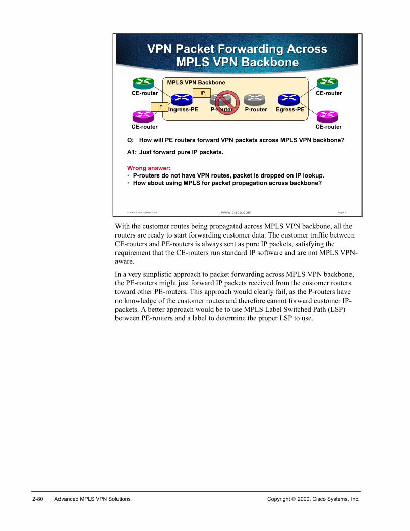
2-80 Advanced MPLS VPN Solutions Copyright 2000, Cisco Systems, Inc.
© 2000, Cisco Systems, Inc. www.cisco.com Page93
VPN Packet Forwarding Across MPLS VPN Backbone
VPN Packet Forwarding Across MPLS VPN Backbone
Q: How will PE routers forward VPN packets across MPLS VPN backbone?
MPLS VPN Backbone
P-routerIngress-PE Egress-PE
CE-router
CE-router CE-router
CE-router
P-routerIP
A1: Just forward pure IP packets.
IP
Wrong answer:• P-routers do not have VPN routes, packet is dropped on IP lookup.• How about using MPLS for packet propagation across backbone?
With the customer routes being propagated across MPLS VPN backbone, all therouters are ready to start forwarding customer data. The customer traffic betweenCE-routers and PE-routers is always sent as pure IP packets, satisfying therequirement that the CE-routers run standard IP software and are not MPLS VPN-aware.
In a very simplistic approach to packet forwarding across MPLS VPN backbone,the PE-routers might just forward IP packets received from the customer routerstoward other PE-routers. This approach would clearly fail, as the P-routers haveno knowledge of the customer routes and therefore cannot forward customer IP-packets. A better approach would be to use MPLS Label Switched Path (LSP)between PE-routers and a label to determine the proper LSP to use.
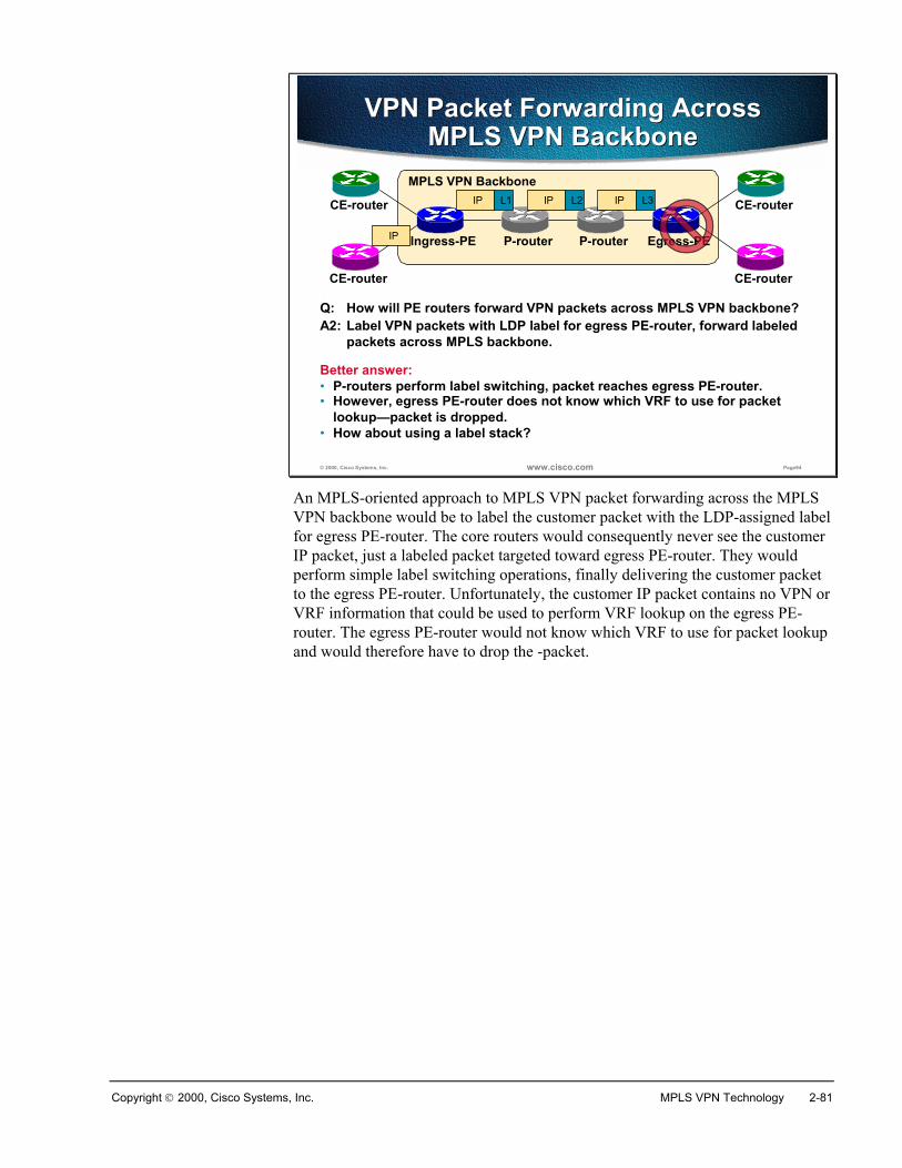
Copyright 2000, Cisco Systems, Inc. MPLS VPN Technology 2-81
© 2000, Cisco Systems, Inc. www.cisco.com Page94
VPN Packet Forwarding Across MPLS VPN Backbone
VPN Packet Forwarding Across MPLS VPN Backbone
Q: How will PE routers forward VPN packets across MPLS VPN backbone?
MPLS VPN Backbone
P-routerIngress-PE Egress-PE
CE-router
CE-router CE-router
CE-router
P-routerIP
A2: Label VPN packets with LDP label for egress PE-router, forward labeledpackets across MPLS backbone.
IP L1
Better answer:• P-routers perform label switching, packet reaches egress PE-router.
IP L2 IP L3
• However, egress PE-router does not know which VRF to use for packetlookup—packet is dropped.
• How about using a label stack?
An MPLS-oriented approach to MPLS VPN packet forwarding across the MPLSVPN backbone would be to label the customer packet with the LDP-assigned labelfor egress PE-router. The core routers would consequently never see the customerIP packet, just a labeled packet targeted toward egress PE-router. They wouldperform simple label switching operations, finally delivering the customer packetto the egress PE-router. Unfortunately, the customer IP packet contains no VPN orVRF information that could be used to perform VRF lookup on the egress PE-router. The egress PE-router would not know which VRF to use for packet lookupand would therefore have to drop the -packet.
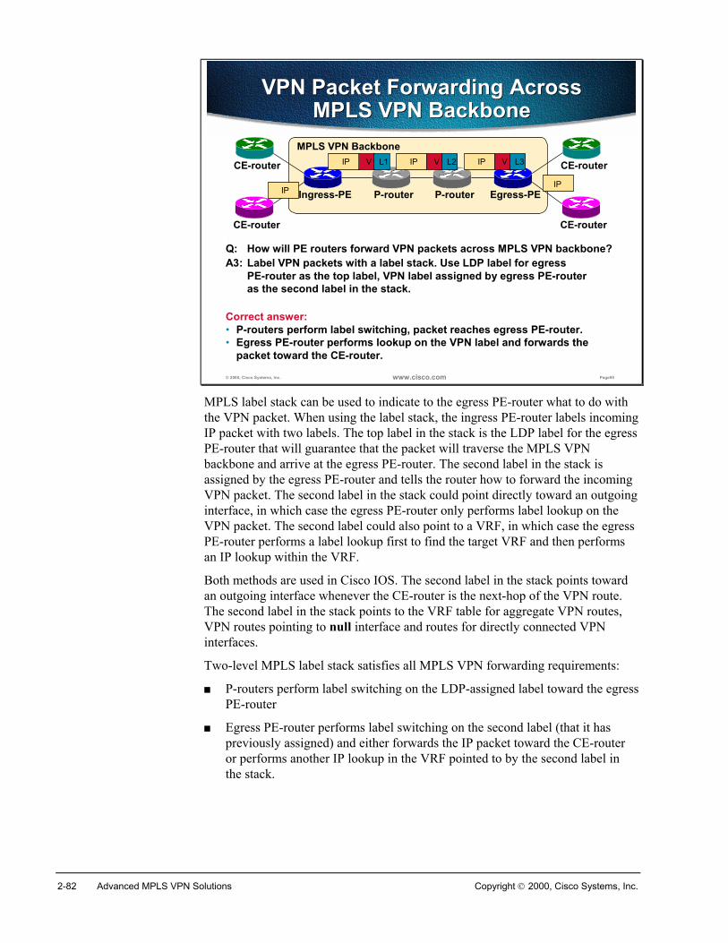
2-82 Advanced MPLS VPN Solutions Copyright 2000, Cisco Systems, Inc.
© 2000, Cisco Systems, Inc. www.cisco.com Page95
VPN Packet Forwarding Across MPLS VPN Backbone
VPN Packet Forwarding Across MPLS VPN Backbone
Q: How will PE routers forward VPN packets across MPLS VPN backbone?
MPLS VPN Backbone
P-routerIngress-PE Egress-PE
CE-router
CE-router CE-router
CE-router
P-routerIP
A3: Label VPN packets with a label stack. Use LDP label for egress PE-router as the top label, VPN label assigned by egress PE-routeras the second label in the stack.
IP V L1 IP V L2 IP V L3
Correct answer:• P-routers perform label switching, packet reaches egress PE-router.• Egress PE-router performs lookup on the VPN label and forwards the
packet toward the CE-router.
IP
MPLS label stack can be used to indicate to the egress PE-router what to do withthe VPN packet. When using the label stack, the ingress PE-router labels incomingIP packet with two labels. The top label in the stack is the LDP label for the egressPE-router that will guarantee that the packet will traverse the MPLS VPNbackbone and arrive at the egress PE-router. The second label in the stack isassigned by the egress PE-router and tells the router how to forward the incomingVPN packet. The second label in the stack could point directly toward an outgoinginterface, in which case the egress PE-router only performs label lookup on theVPN packet. The second label could also point to a VRF, in which case the egressPE-router performs a label lookup first to find the target VRF and then performsan IP lookup within the VRF.
Both methods are used in Cisco IOS. The second label in the stack points towardan outgoing interface whenever the CE-router is the next-hop of the VPN route.The second label in the stack points to the VRF table for aggregate VPN routes,VPN routes pointing to null interface and routes for directly connected VPNinterfaces.
Two-level MPLS label stack satisfies all MPLS VPN forwarding requirements:
� P-routers perform label switching on the LDP-assigned label toward the egressPE-router
� Egress PE-router performs label switching on the second label (that it haspreviously assigned) and either forwards the IP packet toward the CE-routeror performs another IP lookup in the VRF pointed to by the second label inthe stack.
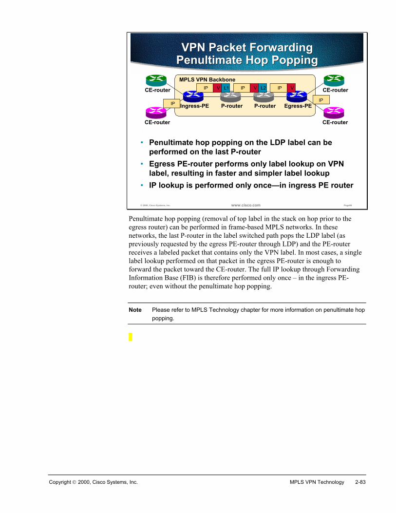
Copyright 2000, Cisco Systems, Inc. MPLS VPN Technology 2-83
© 2000, Cisco Systems, Inc. www.cisco.com Page96
VPN Packet Forwarding Penultimate Hop PoppingVPN Packet Forwarding
Penultimate Hop PoppingMPLS VPN Backbone
P-routerIngress-PE Egress-PE
CE-router
CE-router CE-router
CE-router
P-routerIP
• Penultimate hop popping on the LDP label can be performed on the last P-router
IP V L1 IP V L2 IP V
IP
• Egress PE-router performs only label lookup on VPN label, resulting in faster and simpler label lookup
• IP lookup is performed only once—in ingress PE router
Penultimate hop popping (removal of top label in the stack on hop prior to theegress router) can be performed in frame-based MPLS networks. In thesenetworks, the last P-router in the label switched path pops the LDP label (aspreviously requested by the egress PE-router through LDP) and the PE-routerreceives a labeled packet that contains only the VPN label. In most cases, a singlelabel lookup performed on that packet in the egress PE-router is enough toforward the packet toward the CE-router. The full IP lookup through ForwardingInformation Base (FIB) is therefore performed only once – in the ingress PE-router; even without the penultimate hop popping.
Note Please refer to MPLS Technology chapter for more information on penultimate hoppopping.
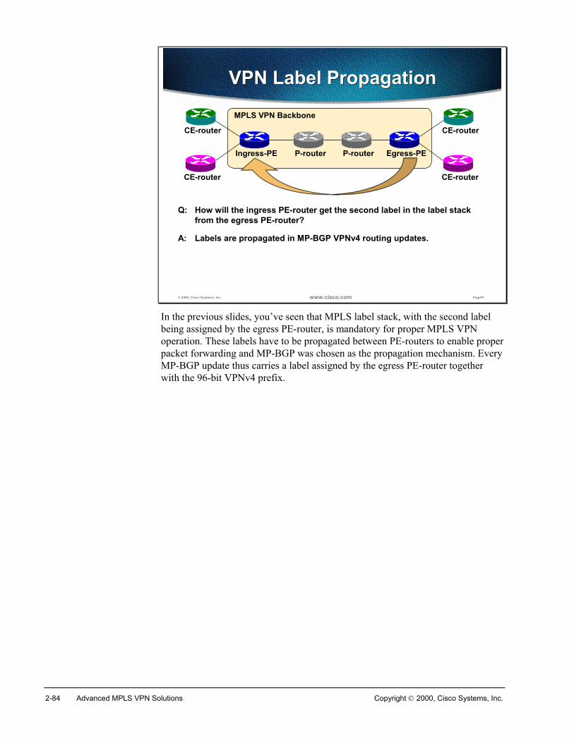
2-84 Advanced MPLS VPN Solutions Copyright 2000, Cisco Systems, Inc.
© 2000, Cisco Systems, Inc. www.cisco.com Page97
VPN Label PropagationVPN Label Propagation
Q: How will the ingress PE-router get the second label in the label stackfrom the egress PE-router?
MPLS VPN Backbone
P-routerIngress-PE Egress-PE
CE-router
CE-router CE-router
CE-router
P-router
A: Labels are propagated in MP-BGP VPNv4 routing updates.
In the previous slides, you’ve seen that MPLS label stack, with the second labelbeing assigned by the egress PE-router, is mandatory for proper MPLS VPNoperation. These labels have to be propagated between PE-routers to enable properpacket forwarding and MP-BGP was chosen as the propagation mechanism. EveryMP-BGP update thus carries a label assigned by the egress PE-router togetherwith the 96-bit VPNv4 prefix.
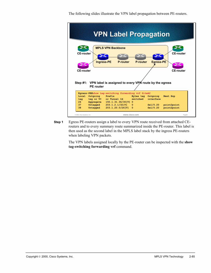
Copyright 2000, Cisco Systems, Inc. MPLS VPN Technology 2-85
The following slides illustrate the VPN label propagation between PE-routers.
© 2000, Cisco Systems, Inc. www.cisco.com Page98
VPN Label PropagationVPN Label Propagation
Step #1: VPN label is assigned to every VPN route by the egressPE router
MPLS VPN Backbone
P-routerIngress-PE Egress-PE
CE-router
CE-router CE-router
CE-router
P-router
Egress-PE#show tag-switching forwarding vrf SiteA2Local Outgoing Prefix Bytes tag Outgoing Next Hoptag tag or VC or Tunnel Id switched interface26 Aggregate 150.1.31.36/30[V] 037 Untagged 203.1.2.1/32[V] 0 Se1/0.20 point2point38 Untagged 203.1.20.0/24[V] 0 Se1/0.20 point2point
Egress-PE#show tag-switching forwarding vrf SiteA2Local Outgoing Prefix Bytes tag Outgoing Next Hoptag tag or VC or Tunnel Id switched interface26 Aggregate 150.1.31.36/30[V] 037 Untagged 203.1.2.1/32[V] 0 Se1/0.20 point2point38 Untagged 203.1.20.0/24[V] 0 Se1/0.20 point2point
Step 1 Egress PE-routers assign a label to every VPN route received from attached CE-routers and to every summary route summarized inside the PE-router. This label isthen used as the second label in the MPLS label stack by the ingress PE-routerswhen labeling VPN packets.
The VPN labels assigned locally by the PE-router can be inspected with the showtag-switching forwarding vrf command.
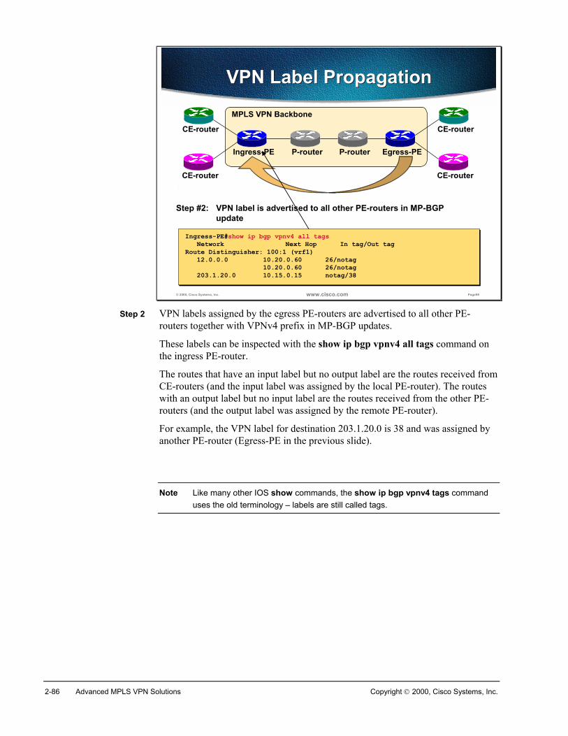
2-86 Advanced MPLS VPN Solutions Copyright 2000, Cisco Systems, Inc.
© 2000, Cisco Systems, Inc. www.cisco.com Page99
VPN Label PropagationVPN Label Propagation
Step #2: VPN label is advertised to all other PE-routers in MP-BGPupdate
MPLS VPN Backbone
P-routerIngress-PE Egress-PE
CE-router
CE-router CE-router
CE-router
P-router
Ingress-PE#show ip bgp vpnv4 all tagsNetwork Next Hop In tag/Out tag
Route Distinguisher: 100:1 (vrf1)12.0.0.0 10.20.0.60 26/notag
10.20.0.60 26/notag203.1.20.0 10.15.0.15 notag/38
Ingress-PE#show ip bgp vpnv4 all tagsNetwork Next Hop In tag/Out tag
Route Distinguisher: 100:1 (vrf1)12.0.0.0 10.20.0.60 26/notag
10.20.0.60 26/notag203.1.20.0 10.15.0.15 notag/38
Step 2 VPN labels assigned by the egress PE-routers are advertised to all other PE-routers together with VPNv4 prefix in MP-BGP updates.
These labels can be inspected with the show ip bgp vpnv4 all tags command onthe ingress PE-router.
The routes that have an input label but no output label are the routes received fromCE-routers (and the input label was assigned by the local PE-router). The routeswith an output label but no input label are the routes received from the other PE-routers (and the output label was assigned by the remote PE-router).
For example, the VPN label for destination 203.1.20.0 is 38 and was assigned byanother PE-router (Egress-PE in the previous slide).
Note Like many other IOS show commands, the show ip bgp vpnv4 tags commanduses the old terminology – labels are still called tags.
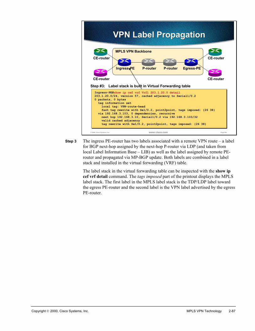
Copyright 2000, Cisco Systems, Inc. MPLS VPN Technology 2-87
© 2000, Cisco Systems, Inc. www.cisco.com Page100
VPN Label PropagationVPN Label Propagation
Step #3: Label stack is built in Virtual Forwarding table
MPLS VPN Backbone
P-routerIngress-PE Egress-PE
CE-router
CE-router CE-router
CE-router
P-router
Ingress-PE#show ip cef vrf Vrf1 203.1.20.0 detail203.1.20.0/24, version 57, cached adjacency to Serial1/0.20 packets, 0 bytes
tag information setlocal tag: VPN-route-headfast tag rewrite with Se1/0.2, point2point, tags imposed: {26 38}
via 192.168.3.103, 0 dependencies, recursivenext hop 192.168.3.10, Serial1/0.2 via 192.168.3.103/32valid cached adjacencytag rewrite with Se1/0.2, point2point, tags imposed: {26 38}
Step 3 The ingress PE-router has two labels associated with a remote VPN route – a labelfor BGP next-hop assigned by the next-hop P-router via LDP (and taken fromlocal Label Information Base – LIB) as well as the label assigned by remote PE-router and propagated via MP-BGP update. Both labels are combined in a labelstack and installed in the virtual forwarding (VRF) table.
The label stack in the virtual forwarding table can be inspected with the show ipcef vrf detail command. The tags imposed part of the printout displays the MPLSlabel stack. The first label in the MPLS label stack is the TDP/LDP label towardthe egress PE-router and the second label is the VPN label advertised by the egressPE-router.
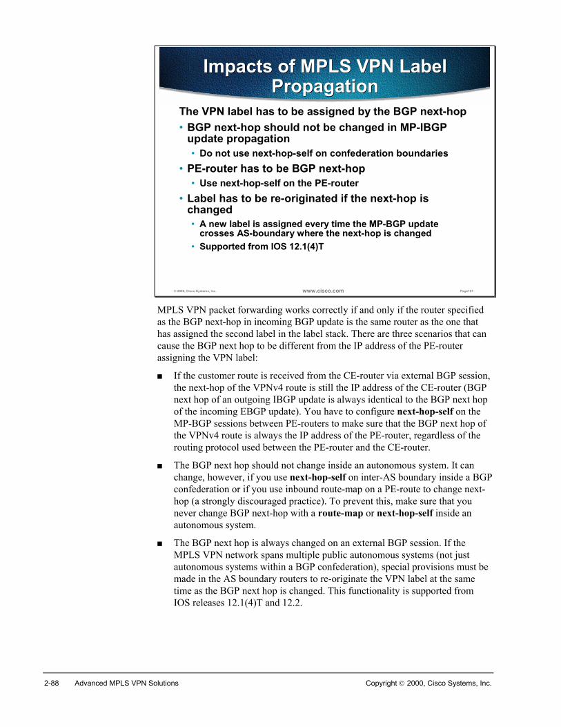
2-88 Advanced MPLS VPN Solutions Copyright 2000, Cisco Systems, Inc.
© 2000, Cisco Systems, Inc. www.cisco.com Page101
Impacts of MPLS VPN Label Propagation
Impacts of MPLS VPN Label Propagation
The VPN label has to be assigned by the BGP next-hop• BGP next-hop should not be changed in MP-IBGP
update propagation• Do not use next-hop-self on confederation boundaries
• PE-router has to be BGP next-hop• Use next-hop-self on the PE-router
• Label has to be re-originated if the next-hop is changed• A new label is assigned every time the MP-BGP update
crosses AS-boundary where the next-hop is changed• Supported from IOS 12.1(4)T
MPLS VPN packet forwarding works correctly if and only if the router specifiedas the BGP next-hop in incoming BGP update is the same router as the one thathas assigned the second label in the label stack. There are three scenarios that cancause the BGP next hop to be different from the IP address of the PE-routerassigning the VPN label:
� If the customer route is received from the CE-router via external BGP session,the next-hop of the VPNv4 route is still the IP address of the CE-router (BGPnext hop of an outgoing IBGP update is always identical to the BGP next hopof the incoming EBGP update). You have to configure next-hop-self on theMP-BGP sessions between PE-routers to make sure that the BGP next hop ofthe VPNv4 route is always the IP address of the PE-router, regardless of therouting protocol used between the PE-router and the CE-router.
� The BGP next hop should not change inside an autonomous system. It canchange, however, if you use next-hop-self on inter-AS boundary inside a BGPconfederation or if you use inbound route-map on a PE-route to change next-hop (a strongly discouraged practice). To prevent this, make sure that younever change BGP next-hop with a route-map or next-hop-self inside anautonomous system.
� The BGP next hop is always changed on an external BGP session. If theMPLS VPN network spans multiple public autonomous systems (not justautonomous systems within a BGP confederation), special provisions must bemade in the AS boundary routers to re-originate the VPN label at the sametime as the BGP next hop is changed. This functionality is supported fromIOS releases 12.1(4)T and 12.2.
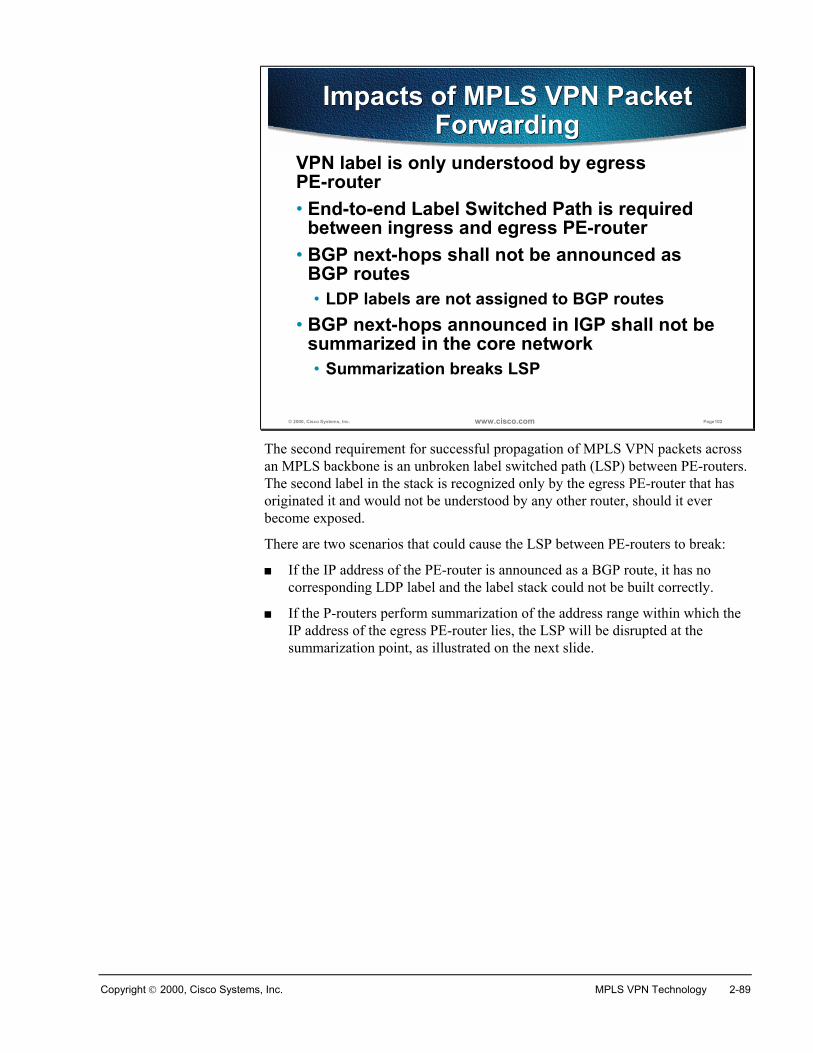
Copyright 2000, Cisco Systems, Inc. MPLS VPN Technology 2-89
© 2000, Cisco Systems, Inc. www.cisco.com Page102
Impacts of MPLS VPN Packet Forwarding
Impacts of MPLS VPN Packet Forwarding
VPN label is only understood by egress PE-router• End-to-end Label Switched Path is required
between ingress and egress PE-router• BGP next-hops shall not be announced as
BGP routes• LDP labels are not assigned to BGP routes
• BGP next-hops announced in IGP shall not be summarized in the core network• Summarization breaks LSP
The second requirement for successful propagation of MPLS VPN packets acrossan MPLS backbone is an unbroken label switched path (LSP) between PE-routers.The second label in the stack is recognized only by the egress PE-router that hasoriginated it and would not be understood by any other router, should it everbecome exposed.
There are two scenarios that could cause the LSP between PE-routers to break:
� If the IP address of the PE-router is announced as a BGP route, it has nocorresponding LDP label and the label stack could not be built correctly.
� If the P-routers perform summarization of the address range within which theIP address of the egress PE-router lies, the LSP will be disrupted at thesummarization point, as illustrated on the next slide.
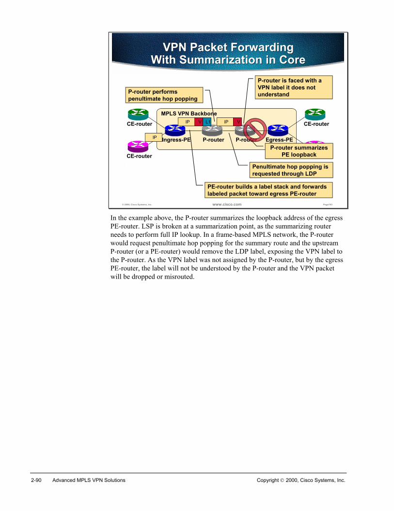
2-90 Advanced MPLS VPN Solutions Copyright 2000, Cisco Systems, Inc.
© 2000, Cisco Systems, Inc. www.cisco.com Page103
VPN Packet Forwarding With Summarization in Core
VPN Packet Forwarding With Summarization in Core
MPLS VPN Backbone
P-routerIngress-PE Egress-PE
CE-router
CE-router CE-router
CE-router
P-routerP-router summarizes
PE loopback
Penultimate hop popping is requested through LDP
IP
IP V L1
PE-router builds a label stack and forwards labeled packet toward egress PE-router
IP V
P-router performs penultimate hop popping
P-router is faced with a VPN label it does not understand
In the example above, the P-router summarizes the loopback address of the egressPE-router. LSP is broken at a summarization point, as the summarizing routerneeds to perform full IP lookup. In a frame-based MPLS network, the P-routerwould request penultimate hop popping for the summary route and the upstreamP-router (or a PE-router) would remove the LDP label, exposing the VPN label tothe P-router. As the VPN label was not assigned by the P-router, but by the egressPE-router, the label will not be understood by the P-router and the VPN packetwill be dropped or misrouted.
Copyright 2000, Cisco Systems, Inc. MPLS VPN Technology 2-91
SummaryCustomer VPN packets are forwarded across MPLS VPN backbone encapsulatedin an MPLS label stack composed of two labels:
� The top label in the stack is the LDP-assigned label toward the egress PE-router
� The second label in the stack is the VPN label assigned by the egress PE-router and propagated to other PE-routers in the MP-BGP update togetherwith the VPNv4 route
Successful forwarding of customer data packets across MPLS VPN backbone canonly happen if the label switched path between ingress and egress PE-router isunbroken and if the router that is specified as the BGP next hop assigns the VPNlabel. There are a number of scenarios that can cause MPLS VPN connectivity tobreak:
� BGP next hop is the IP address of the CE-router – fix by specifying next-hop-self on the PE-router
� BGP next hop is changed inside the autonomous system – fix by removingnext-hop-self on BGP confederation boundary or by removing set next-hopfrom inbound route-maps
� BGP next hop is changed when the MP-BGP update crosses autonomoussystem boundary – this is the default BGP behavior that cannot be changed,use IOS release that supports inter-AS MPLS VPN (starting with IOS12.1(4)T)
� Label switched path is broken between the PE-routers, for example due toroute summarization in the MPLS core.
Review QuestionsAnswer the following questions:
� How are VPN packets propagated across MPLS VPN backbone?
� How can P-routers forward VPN packets if they don’t have VPN routes?
� How is the VPN label propagated between PE-routers?
� Which router assigns the VPN label?
� How is the VPN label used on other PE-routers?
� What is the impact of changing BGP next-hop on MP-BGP update?
� How are MP-BGP updates propagated across AS boundary?
� What is the impact of BGP next-hop summarization in the network core?
2-92 Advanced MPLS VPN Solutions Copyright 2000, Cisco Systems, Inc.
Lesson SummaryAfter completing this lesson, you should be able to perform the following tasks:
� Identify major Virtual Private network topologies, their characteristics andusage scenarios
� Describe the differences between overlay VPN and peer-to-peer VPN
� List major technologies supporting overlay VPNs and peer-to-peer VPNs
� Position MPLS VPN in comparison with other peer-to-peer VPNimplementations
� Describe major architectural blocks of MPLS VPN
� Describe MPLS VPN routing model and packet forwarding
Copyright 2000, Cisco Systems, Inc. MPLS VPN Technology 2-93
Answers to Review Questions
Introduction to Virtual Private Networks� Why are customers interested in Virtual Private Networks?
Customers use VPNs to reduce their connectivity costs.
� What is the main role of a VPN?
Virtual Private Networks replace private point-to-point links withconnectivity over statistically shared infrastructure.
� What is a C-network?
The C-network is the part of the network under customer control.
� What is a customer site?
Customer site is a contiguous part of the C-network
� What is a CE-router?
The CE-router is a router in the C-network with a link to the ServiceProvider network
� What is a P-network?
The P-network is part of the network under Service Provider control
� What is the difference between a PE-device and a P-device?
Customers are attached only to PE-devices, not to P-devices.
Overlay and Peer-to-Peer VPN� What is an overlay VPN?
An overlay VPN is a VPN providing emulated point-to-point links to thecustomers.
� Which routing protocol runs between the customer and the service provider inan overlay VPN?
There customer routing protocol in not extended to the Service Provider.The only routing protocol running between the customer and the serviceprovider is the routing protocol needed to implement underlying ServiceProvider connectivity.
� Which routers are routing protocol neighbors of a CE-router in overlay VPN?
In overlay VPN implementations, the CE-routers peer directly.
� List three IP-based overlay VPN technologies.
Generic Route Encapsulation (GRE), IP Security (IPSec) and PPPforwarding. PPP forwarding can be implemented with Layer-2Forwarding (L2F), Layer-2 Transport Protocol (L2TP) or Point-to-PointTransport Protocol (PPTP).
2-94 Advanced MPLS VPN Solutions Copyright 2000, Cisco Systems, Inc.
� What is the major benefit of peer-to-peer VPN as compared to overlay VPN?
Peer-to-peer VPN guarantee optimum routing between customer siteswithout the need for full-mesh of virtual circuits.
� List two traditional peer-to-peer VPN implementations?
Peer-to-peer VPN can be implemented with IP packet filters on sharedPE-routers or split routing with dedicated per-customer PE-routers.
� What is the drawback of all traditional peer-to-peer VPN implementations?
The customers cannot use private IP addresses in traditional peer-to-peerVPN implementations.
Major VPN Topologies� What are the major Overlay VPN topologies
The major overlay VPN topologies are hub-and-spoke, partial mesh andfull mesh.
� Why would the customers prefer partial mesh over full mesh topology?
Connectivity costs usually dictate use of partial mesh.
� What is the difference between an Intranet and an Extranet?
Intranet links sites within an organization, extranet links sites fromdifferent organizations. Security is usually not an issue inside anIntranet, but becomes major concern in an Extranet.
� What is the difference between a simple VPN and a Central Services VPN?
Every customer site can exchange traffic with every other customer sitein simple VPN. In central services VPN, the client sites can onlyexchange traffic with server sites.
� What are the connectivity requirements of a Central Services VPN?
Client sites can only talk to the server sites. Server sites have unlimitedconnectivity.
MPLS VPN Architecture� How does MPLS VPN support overlapping customer address spaces?
MPLS VPN supports overlapping customer address spaces by usingindependent per-VPN routing tables.
� How are customer routes exchanged across the P-network?
Multi-protocol BGP (MP-BGP) is used to exchange customer routesacross the P-network.
� What is a route distinguisher?
The route-distinguisher as a 64-bit prefix prepended to customer IPv4address to make it globally unique.
Copyright 2000, Cisco Systems, Inc. MPLS VPN Technology 2-95
� Why is the RD not usable as VPN identifier?
The RD cannot be used as VPN identifier since it cannot supportcomplex VPN topologies where a single site belongs to multiple VPNs.
� Why were the route targets introduced in MPLS VPN architecture?
Route targets were introduced to support complex VPN topologies.
� What is a route target?
Route target is a 64-bit value attached to a BGP route as extended BGPcommunity.
� How are route targets used to build virtual routing tables in the PE routers?
Every customer route exported from a VRF is tagged with appropriateexport route targets. VPN Routes received by a PE-router are matchedagainst import route targets configured in a VRF.
� What is the impact of complex VPN topologies on virtual routing tables in thePE routers?
Complex VPN topologies might require more than one VRF per VPN.
MPLS VPN Routing Model� What is the impact of MPLS VPN on CE-routers
The CE-routers are not MPLS VPN-aware.
� What is the customer’s perception of end-to-end MPLS VPN routing?
The customer perceives the MPLS VPN backbone as BGP backbone inits own network.
� What is the P-router perception of end-to-end MPLS VPN routing?
P-router is not MPLS VPN aware. It only sees global subnets in theMPLS VPN backbone, not the customer routes.
� How many routing tables does a PE-router have?
A PE-router has a global routing table and several virtual routing tables.
� How many routing tables reside on a P-router?
The P-router only has the global routing table.
� Which routing protocols fill the global routing table of a PE-router?
The global routing table in the PE-router is filled with information fromthe backbone IGP and the global BGP process.
� Which routing protocols fill the Virtual Routing table (VRF) of a PE-router
The VRF table is filled with information from the VRF routing protocolsrunning between the PE-routers and the CE-routers and with theinformation received by the PE-routers through MP-BGP.
� How is the Internet routing supported by MPLS VPN architecture?
Internet routing is still supported in the global IP routing table.
� How is the VPN routing information exchanged between the PE-routers?
2-96 Advanced MPLS VPN Solutions Copyright 2000, Cisco Systems, Inc.
PE-routers exchange VPN routing information with MP-BGP.
� Which attributes are always present in a MP-BGP update?
Every MP-BGP update carries VPNv4 prefix, route-targets, MPLS VPNlabel and all mandatory BGP attributes (AS-path, origin, BGP next-hop).
� Which attributes can be optionally present in a MP-BGP update?
Any other discretionary or optional BGP attribute can be present in MP-BGP update.
� Which BGP attributes drive the import of VPNv4 route into a VRF?
Route targets control the import of VPNv4 routes into VRFs.
� Which BGP attributes control the VPN route distribution toward CE-routers?
Site-of-origin controls the distribution of VPN routes toward CE-routers.
MPLS VPN Packet Forwarding� How are VPN packets propagated across MPLS VPN backbone?
The VPN packets are propagated across MPLS VPN backbone aslabeled packets with two labels in the MPLS label stack.
� How can P-routers forward VPN packets if they don’t have VPN routes?
The P-routers only perform label lookup and thus never see the VPNpackets.
� How is the VPN label propagated between PE-routers?
VPN labels are attached to the VPNv4 routes in MP-BGP updates.
� Which router assigns the VPN label?
The egress PE-router assigns the VPN label.
� How is the VPN label used on other PE-routers?
All other PE-routers use the VPN label assigned by the PE-router as thesecond label in the MPLS label stack.
� What is the impact of changing BGP next-hop on MP-BGP update?
MPLS VPN connectivity is broken unless the MPLS VPN label is re-originated.
� How are MP-BGP updates propagated across AS boundary?
Routers propagating MP-BGP updates across AS-boundary have to re-originate the MPLS VPN labels.
� What is the impact of BGP next-hop summarization in the network core?
MPLS VPN connectivity is broken if the BGP next-hops aresummarized in the network core.
3
MPLS/VPNConfiguration onIOS Platforms
OverviewThis lesson covers MPLS/VPN configuration on Cisco IOS platforms. It includesthe following topics:
� MPLS/VPN Mechanisms in Cisco IOS� Configuring Virtual Routing and Forwarding Tables� Configuring a Multi-Protocol BGP session between the PE routers� Configuring Routing Protocols between PE and CE routers� Monitoring an MPLS/VPN Operation� Troubleshooting MPLS/VPN� Advanced VRF Import/Export Features� Advanced PE-CE BGP Configuration
ObjectivesUpon completion of this lesson, you will be able to perform the following tasks:
� Configure Virtual Routing and Forwarding tables� Configure Multi-protocol BGP in a MPLS/VPN backbone� Configure PE-CE routing protocols� Configure advanced MPLS/VPN features� Monitor MPLS/VPN operations� Troubleshoot MPLS/VPN implementation
3-2 Advanced MPLS VPN Solutions Copyright 2000, Cisco Systems, Inc.
MPLS/VPN Mechanisms in Cisco IOS
ObjectivesUpon completion of this section, you will be able to perform the following tasks:
� Describe the concept of Virtual Routing and Forwarding table
� Describe the concept of routing protocol contexts
� Describe the interaction between PE-CE routing protocols, backbone MP-BGP and virtual routing and forwarding tables
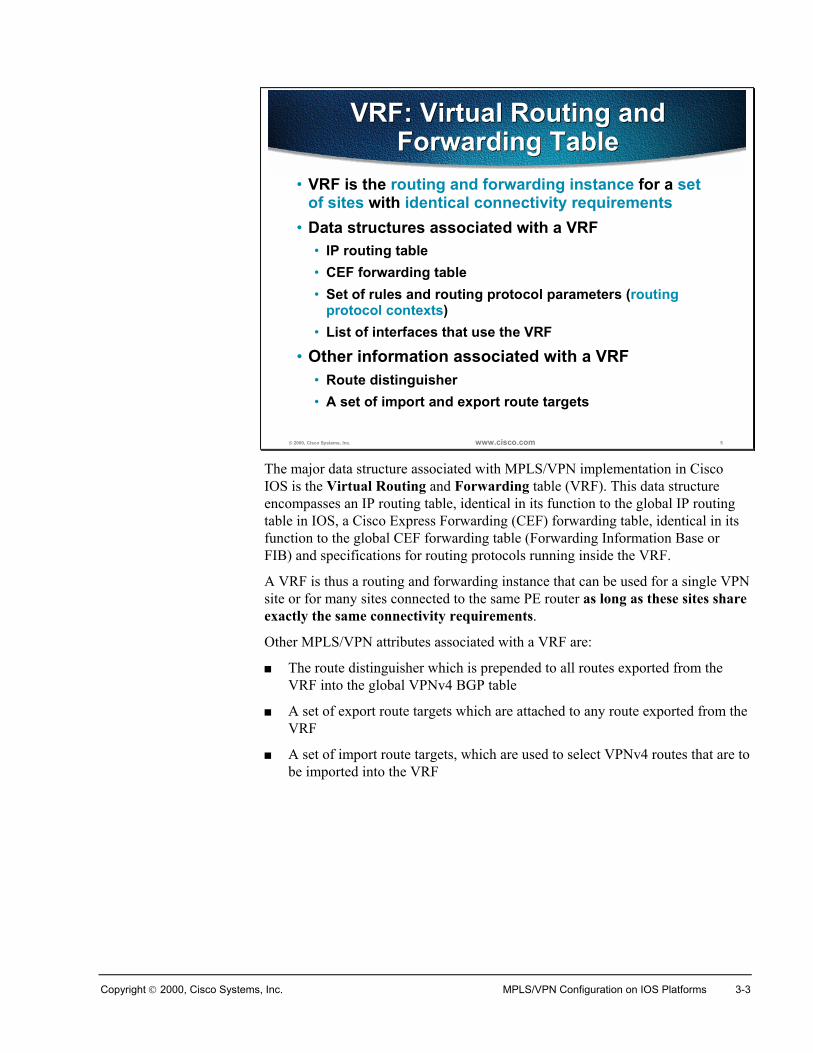
Copyright 2000, Cisco Systems, Inc. MPLS/VPN Configuration on IOS Platforms 3-3
© 2000, Cisco Systems, Inc. www.cisco.com 5
VRF: Virtual Routing andForwarding Table
VRF: Virtual Routing andForwarding Table
• VRF is the routing and forwarding instance for a setof sites with identical connectivity requirements
• Data structures associated with a VRF• IP routing table• CEF forwarding table• Set of rules and routing protocol parameters (routing
protocol contexts)• List of interfaces that use the VRF
• Other information associated with a VRF• Route distinguisher• A set of import and export route targets
The major data structure associated with MPLS/VPN implementation in CiscoIOS is the Virtual Routing and Forwarding table (VRF). This data structureencompasses an IP routing table, identical in its function to the global IP routingtable in IOS, a Cisco Express Forwarding (CEF) forwarding table, identical in itsfunction to the global CEF forwarding table (Forwarding Information Base orFIB) and specifications for routing protocols running inside the VRF.
A VRF is thus a routing and forwarding instance that can be used for a single VPNsite or for many sites connected to the same PE router as long as these sites shareexactly the same connectivity requirements.
Other MPLS/VPN attributes associated with a VRF are:
� The route distinguisher which is prepended to all routes exported from theVRF into the global VPNv4 BGP table
� A set of export route targets which are attached to any route exported from theVRF
� A set of import route targets, which are used to select VPNv4 routes that are tobe imported into the VRF
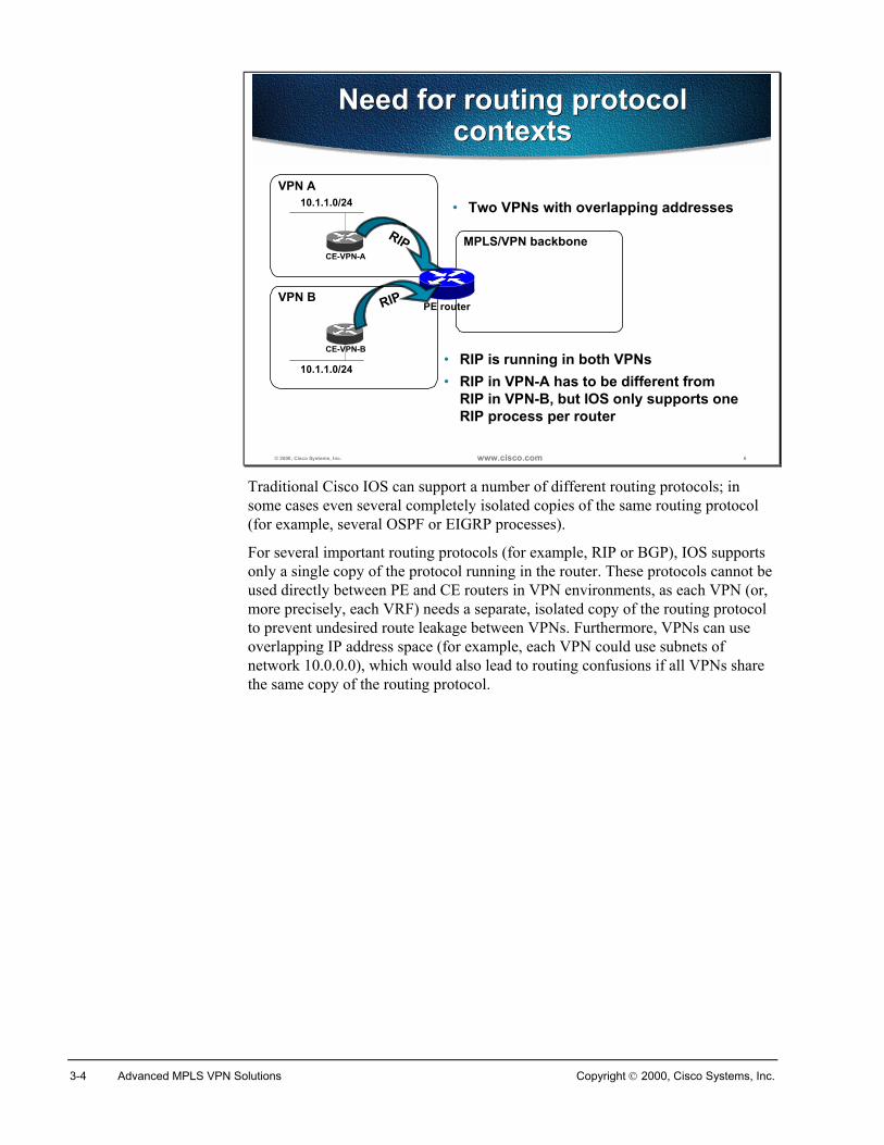
3-4 Advanced MPLS VPN Solutions Copyright 2000, Cisco Systems, Inc.
© 2000, Cisco Systems, Inc. www.cisco.com 6
Need for routing protocolcontexts
Need for routing protocolcontexts
MPLS/VPN backbone
VPN B
VPN A
CE-VPN-A
10.1.1.0/24
CE-VPN-B
10.1.1.0/24
PE router
• Two VPNs with overlapping addresses
RIP
RIP
• RIP is running in both VPNs• RIP in VPN-A has to be different from
RIP in VPN-B, but IOS only supports oneRIP process per router
Traditional Cisco IOS can support a number of different routing protocols; insome cases even several completely isolated copies of the same routing protocol(for example, several OSPF or EIGRP processes).
For several important routing protocols (for example, RIP or BGP), IOS supportsonly a single copy of the protocol running in the router. These protocols cannot beused directly between PE and CE routers in VPN environments, as each VPN (or,more precisely, each VRF) needs a separate, isolated copy of the routing protocolto prevent undesired route leakage between VPNs. Furthermore, VPNs can useoverlapping IP address space (for example, each VPN could use subnets ofnetwork 10.0.0.0), which would also lead to routing confusions if all VPNs sharethe same copy of the routing protocol.
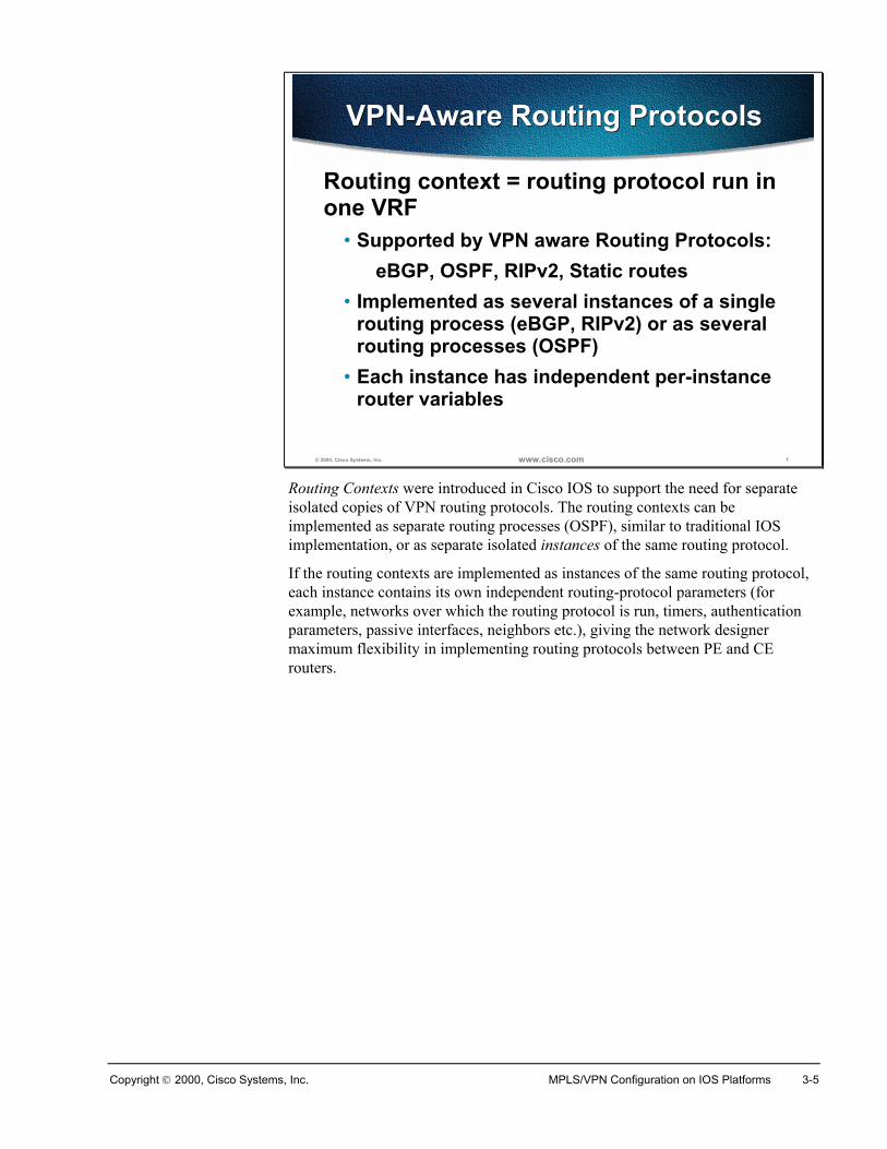
Copyright 2000, Cisco Systems, Inc. MPLS/VPN Configuration on IOS Platforms 3-5
© 2000, Cisco Systems, Inc. www.cisco.com 7
VPN-Aware Routing ProtocolsVPN-Aware Routing Protocols
Routing context = routing protocol run inone VRF
• Supported by VPN aware Routing Protocols:eBGP, OSPF, RIPv2, Static routes
• Implemented as several instances of a singlerouting process (eBGP, RIPv2) or as severalrouting processes (OSPF)
• Each instance has independent per-instancerouter variables
Routing Contexts were introduced in Cisco IOS to support the need for separateisolated copies of VPN routing protocols. The routing contexts can beimplemented as separate routing processes (OSPF), similar to traditional IOSimplementation, or as separate isolated instances of the same routing protocol.
If the routing contexts are implemented as instances of the same routing protocol,each instance contains its own independent routing-protocol parameters (forexample, networks over which the routing protocol is run, timers, authenticationparameters, passive interfaces, neighbors etc.), giving the network designermaximum flexibility in implementing routing protocols between PE and CErouters.
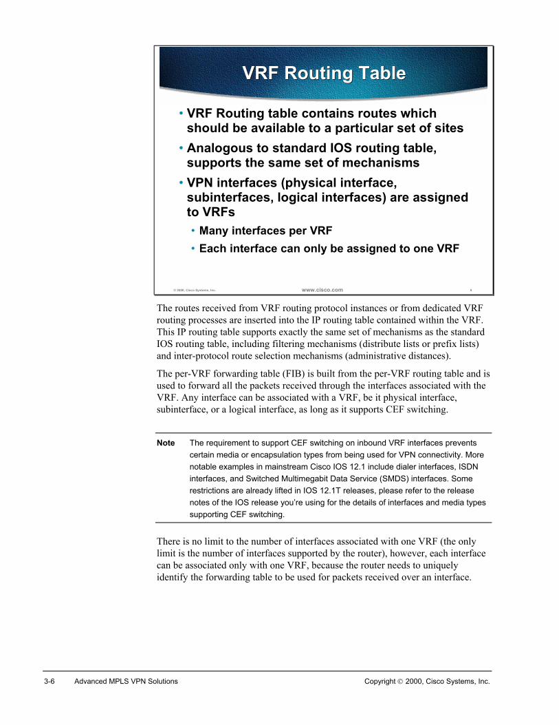
3-6 Advanced MPLS VPN Solutions Copyright 2000, Cisco Systems, Inc.
© 2000, Cisco Systems, Inc. www.cisco.com 8
VRF Routing TableVRF Routing Table
• VRF Routing table contains routes whichshould be available to a particular set of sites
• Analogous to standard IOS routing table,supports the same set of mechanisms
• VPN interfaces (physical interface,subinterfaces, logical interfaces) are assignedto VRFs• Many interfaces per VRF• Each interface can only be assigned to one VRF
The routes received from VRF routing protocol instances or from dedicated VRFrouting processes are inserted into the IP routing table contained within the VRF.This IP routing table supports exactly the same set of mechanisms as the standardIOS routing table, including filtering mechanisms (distribute lists or prefix lists)and inter-protocol route selection mechanisms (administrative distances).
The per-VRF forwarding table (FIB) is built from the per-VRF routing table and isused to forward all the packets received through the interfaces associated with theVRF. Any interface can be associated with a VRF, be it physical interface,subinterface, or a logical interface, as long as it supports CEF switching.
Note The requirement to support CEF switching on inbound VRF interfaces preventscertain media or encapsulation types from being used for VPN connectivity. Morenotable examples in mainstream Cisco IOS 12.1 include dialer interfaces, ISDNinterfaces, and Switched Multimegabit Data Service (SMDS) interfaces. Somerestrictions are already lifted in IOS 12.1T releases, please refer to the releasenotes of the IOS release you’re using for the details of interfaces and media typessupporting CEF switching.
There is no limit to the number of interfaces associated with one VRF (the onlylimit is the number of interfaces supported by the router), however, each interfacecan be associated only with one VRF, because the router needs to uniquelyidentify the forwarding table to be used for packets received over an interface.
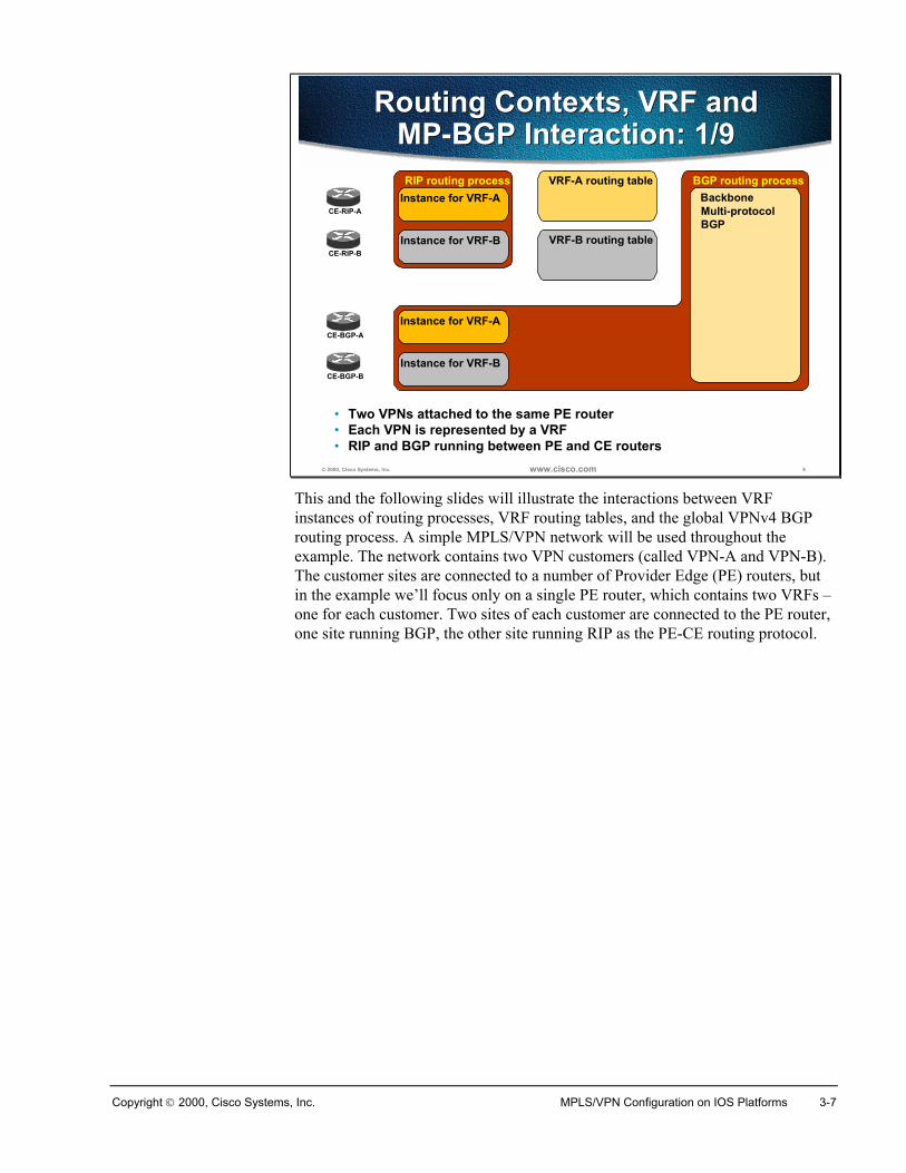
Copyright 2000, Cisco Systems, Inc. MPLS/VPN Configuration on IOS Platforms 3-7
© 2000, Cisco Systems, Inc. www.cisco.com 9
Routing Contexts, VRF andMP-BGP Interaction: 1/9
Routing Contexts, VRF andMP-BGP Interaction: 1/9
VRF-A routing tableRIP routing process
CE-RIP-AInstance for VRF-A
Instance for VRF-BCE-RIP-B
VRF-B routing table
BGP routing processBackboneMulti-protocol BGP
Instance for VRF-A
Instance for VRF-B
CE-BGP-A
CE-BGP-B
• Two VPNs attached to the same PE router• Each VPN is represented by a VRF• RIP and BGP running between PE and CE routers
This and the following slides will illustrate the interactions between VRFinstances of routing processes, VRF routing tables, and the global VPNv4 BGProuting process. A simple MPLS/VPN network will be used throughout theexample. The network contains two VPN customers (called VPN-A and VPN-B).The customer sites are connected to a number of Provider Edge (PE) routers, butin the example we’ll focus only on a single PE router, which contains two VRFs –one for each customer. Two sites of each customer are connected to the PE router,one site running BGP, the other site running RIP as the PE-CE routing protocol.
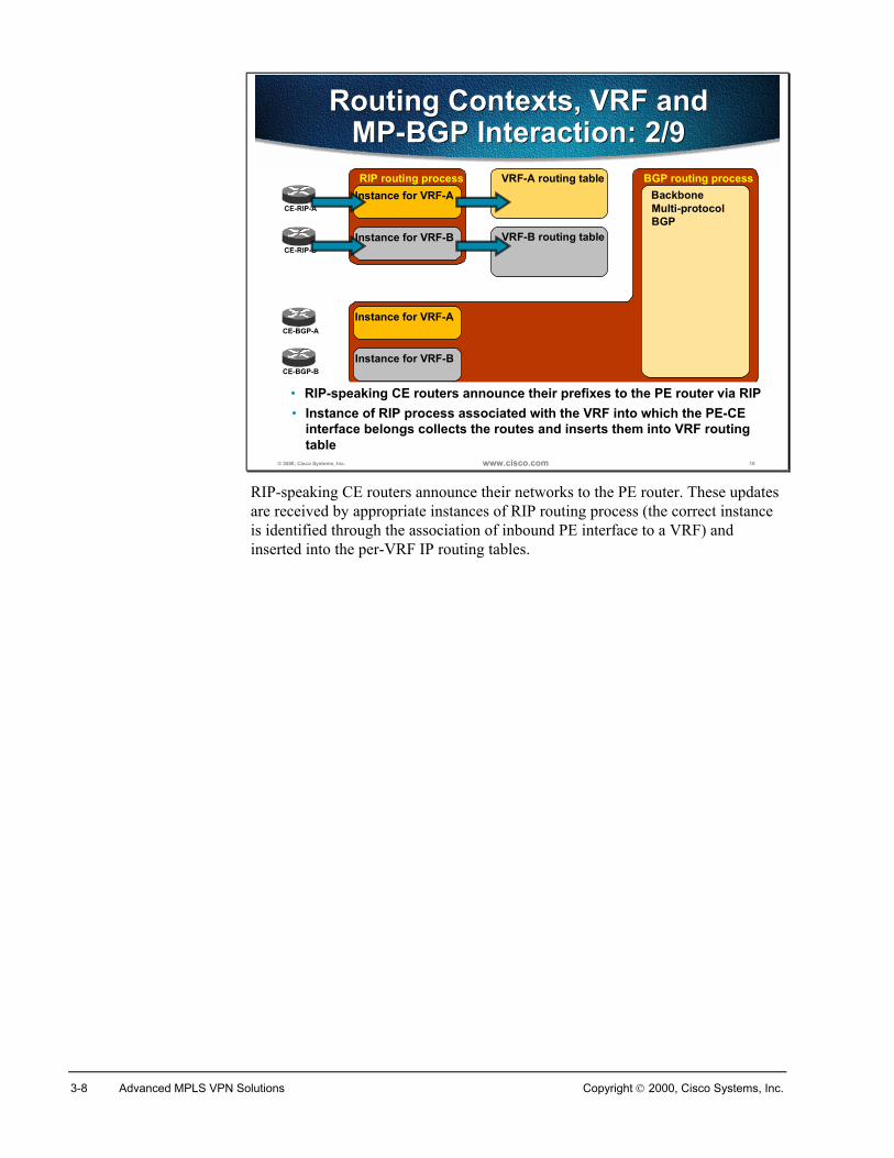
3-8 Advanced MPLS VPN Solutions Copyright 2000, Cisco Systems, Inc.
© 2000, Cisco Systems, Inc. www.cisco.com 10
Routing Contexts, VRF andMP-BGP Interaction: 2/9
Routing Contexts, VRF andMP-BGP Interaction: 2/9
VRF-A routing tableRIP routing process
CE-RIP-AInstance for VRF-A
Instance for VRF-BCE-RIP-B
VRF-B routing table
BGP routing processBackboneMulti-protocol BGP
Instance for VRF-A
Instance for VRF-B
CE-BGP-A
CE-BGP-B
• RIP-speaking CE routers announce their prefixes to the PE router via RIP• Instance of RIP process associated with the VRF into which the PE-CE
interface belongs collects the routes and inserts them into VRF routingtable
RIP-speaking CE routers announce their networks to the PE router. These updatesare received by appropriate instances of RIP routing process (the correct instanceis identified through the association of inbound PE interface to a VRF) andinserted into the per-VRF IP routing tables.
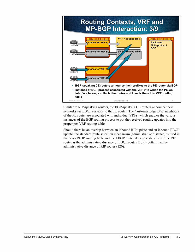
Copyright 2000, Cisco Systems, Inc. MPLS/VPN Configuration on IOS Platforms 3-9
© 2000, Cisco Systems, Inc. www.cisco.com 11
Routing Contexts, VRF andMP-BGP Interaction: 3/9
Routing Contexts, VRF andMP-BGP Interaction: 3/9
VRF-A routing tableRIP routing process
CE-RIP-AInstance for VRF-A
Instance for VRF-BCE-RIP-B
VRF-B routing table
BGP routing processBackboneMulti-protocol BGP
Instance for VRF-A
Instance for VRF-B
CE-BGP-A
CE-BGP-B
• BGP-speaking CE routers announce their prefixes to the PE router via BGP• Instance of BGP process associated with the VRF into which the PE-CE
interface belongs collects the routes and inserts them into VRF routingtable
Similar to RIP-speaking routers, the BGP-speaking CE routers announce theirnetworks via EBGP sessions to the PE router. The Customer Edge BGP neighborsof the PE router are associated with individual VRFs, which enables the variousinstances of the BGP routing process to put the received routing updates into theproper per-VRF routing table.
Should there be an overlap between an inbound RIP update and an inbound EBGPupdate, the standard route selection mechanism (administrative distance) is used inthe per-VRF IP routing table and the EBGP route takes precedence over the RIProute, as the administrative distance of EBGP routes (20) is better than theadministrative distance of RIP routes (120).
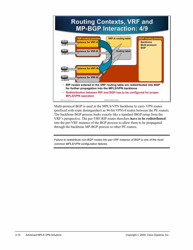
3-10 Advanced MPLS VPN Solutions Copyright 2000, Cisco Systems, Inc.
© 2000, Cisco Systems, Inc. www.cisco.com 12
Routing Contexts, VRF andMP-BGP Interaction: 4/9
Routing Contexts, VRF andMP-BGP Interaction: 4/9
VRF-A routing tableRIP routing process
CE-RIP-AInstance for VRF-A
Instance for VRF-BCE-RIP-B
VRF-B routing table
BGP routing processBackboneMulti-protocol BGP
Instance for VRF-A
Instance for VRF-B
CE-BGP-A
CE-BGP-B
• Redistribution between RIP and BGP has to be configured for properMPLS/VPN operation
• RIP routes entered in the VRF routing table are redistributed into BGP for further propagation into the MPLS/VPN backbone
Multi-protocol BGP is used in the MPLS/VPN backbone to carry VPN routes(prefixed with route distinguisher) as 96-bit VPNv4 routes between the PE routers.The backbone BGP process looks exactly like a standard IBGP setup from theVRF’s perspective. The per-VRF RIP routes therefore have to be redistributedinto the per-VRF instance of the BGP process to allow them to be propagatedthrough the backbone MP-BGP process to other PE routers.
Failure to redistribute non-BGP routes into per-VRF instance of BGP is one of the mostcommon MPLS/VPN configuration failures.
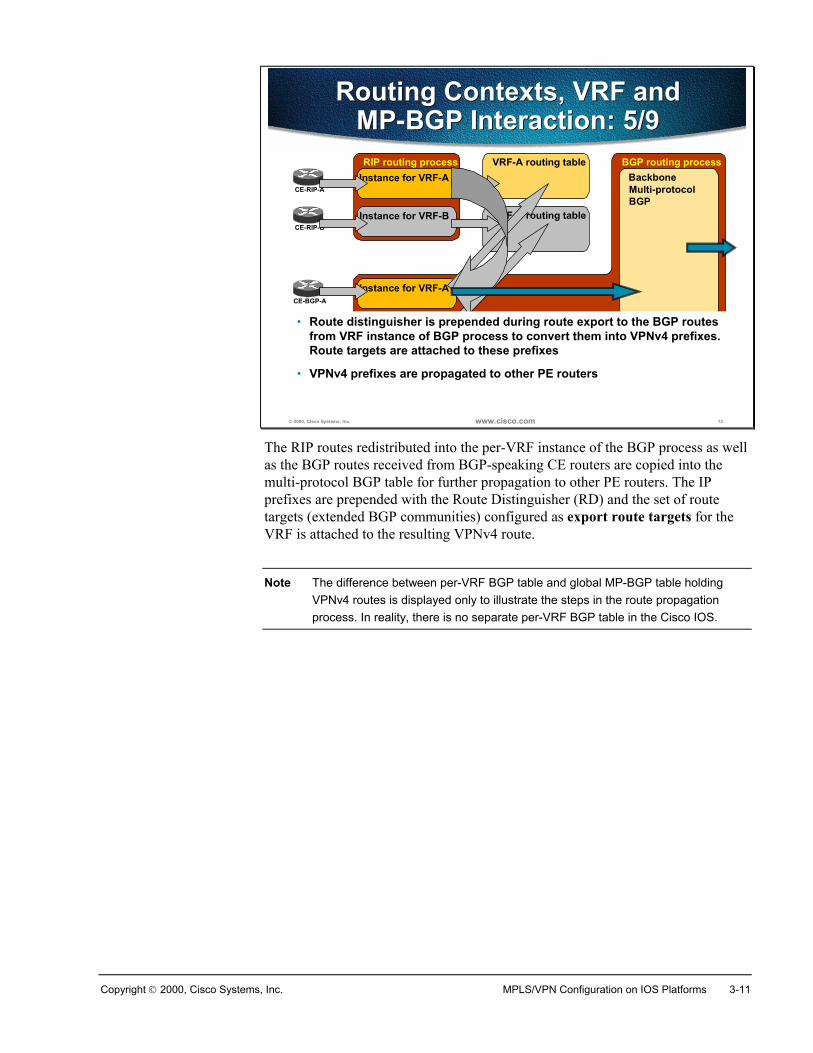
Copyright 2000, Cisco Systems, Inc. MPLS/VPN Configuration on IOS Platforms 3-11
© 2000, Cisco Systems, Inc. www.cisco.com 13
Routing Contexts, VRF andMP-BGP Interaction: 5/9
Routing Contexts, VRF andMP-BGP Interaction: 5/9
VRF-A routing tableRIP routing process
CE-RIP-AInstance for VRF-A
Instance for VRF-BCE-RIP-B
VRF-B routing table
BGP routing processBackboneMulti-protocol BGP
Instance for VRF-A
Instance for VRF-B
CE-BGP-A
CE-BGP-B
• VPNv4 prefixes are propagated to other PE routers
• Route distinguisher is prepended during route export to the BGP routes from VRF instance of BGP process to convert them into VPNv4 prefixes. Route targets are attached to these prefixes
The RIP routes redistributed into the per-VRF instance of the BGP process as wellas the BGP routes received from BGP-speaking CE routers are copied into themulti-protocol BGP table for further propagation to other PE routers. The IPprefixes are prepended with the Route Distinguisher (RD) and the set of routetargets (extended BGP communities) configured as export route targets for theVRF is attached to the resulting VPNv4 route.
Note The difference between per-VRF BGP table and global MP-BGP table holdingVPNv4 routes is displayed only to illustrate the steps in the route propagationprocess. In reality, there is no separate per-VRF BGP table in the Cisco IOS.
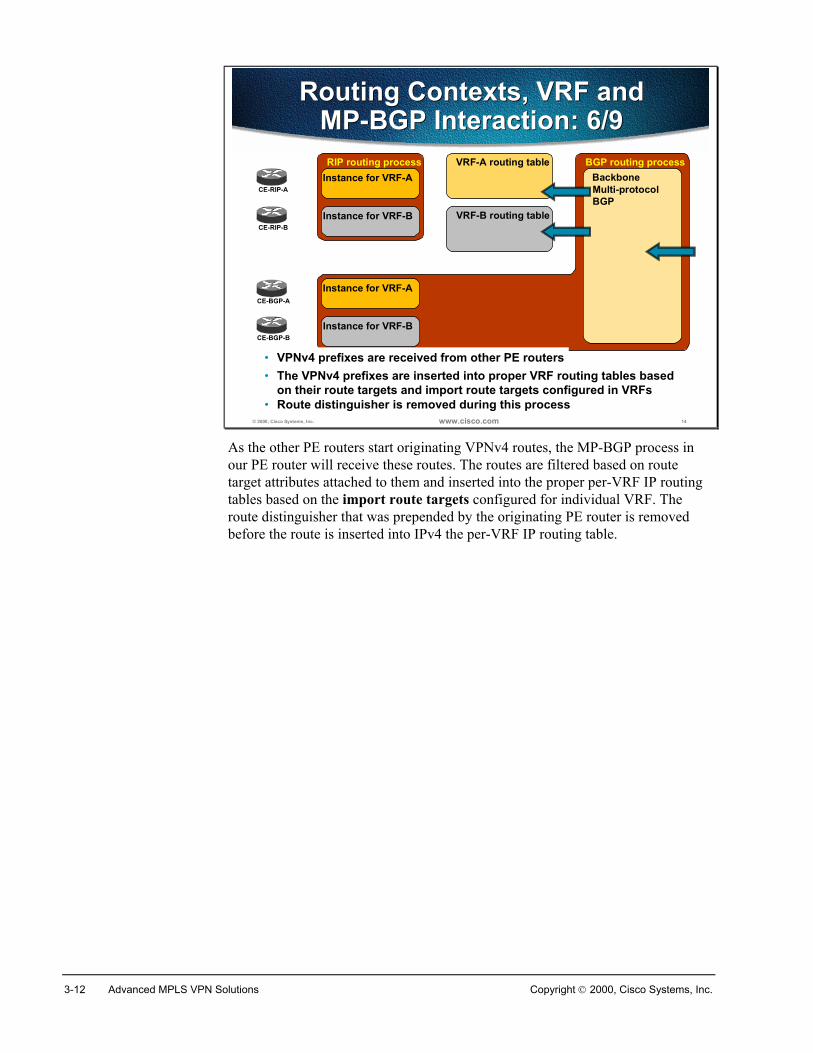
3-12 Advanced MPLS VPN Solutions Copyright 2000, Cisco Systems, Inc.
© 2000, Cisco Systems, Inc. www.cisco.com 14
Routing Contexts, VRF andMP-BGP Interaction: 6/9
Routing Contexts, VRF andMP-BGP Interaction: 6/9
VRF-A routing tableRIP routing process
CE-RIP-AInstance for VRF-A
Instance for VRF-BCE-RIP-B
VRF-B routing table
BGP routing processBackboneMulti-protocol BGP
Instance for VRF-A
Instance for VRF-B
CE-BGP-A
CE-BGP-B
• The VPNv4 prefixes are inserted into proper VRF routing tables based on their route targets and import route targets configured in VRFs
• Route distinguisher is removed during this process
• VPNv4 prefixes are received from other PE routers
As the other PE routers start originating VPNv4 routes, the MP-BGP process inour PE router will receive these routes. The routes are filtered based on routetarget attributes attached to them and inserted into the proper per-VRF IP routingtables based on the import route targets configured for individual VRF. Theroute distinguisher that was prepended by the originating PE router is removedbefore the route is inserted into IPv4 the per-VRF IP routing table.
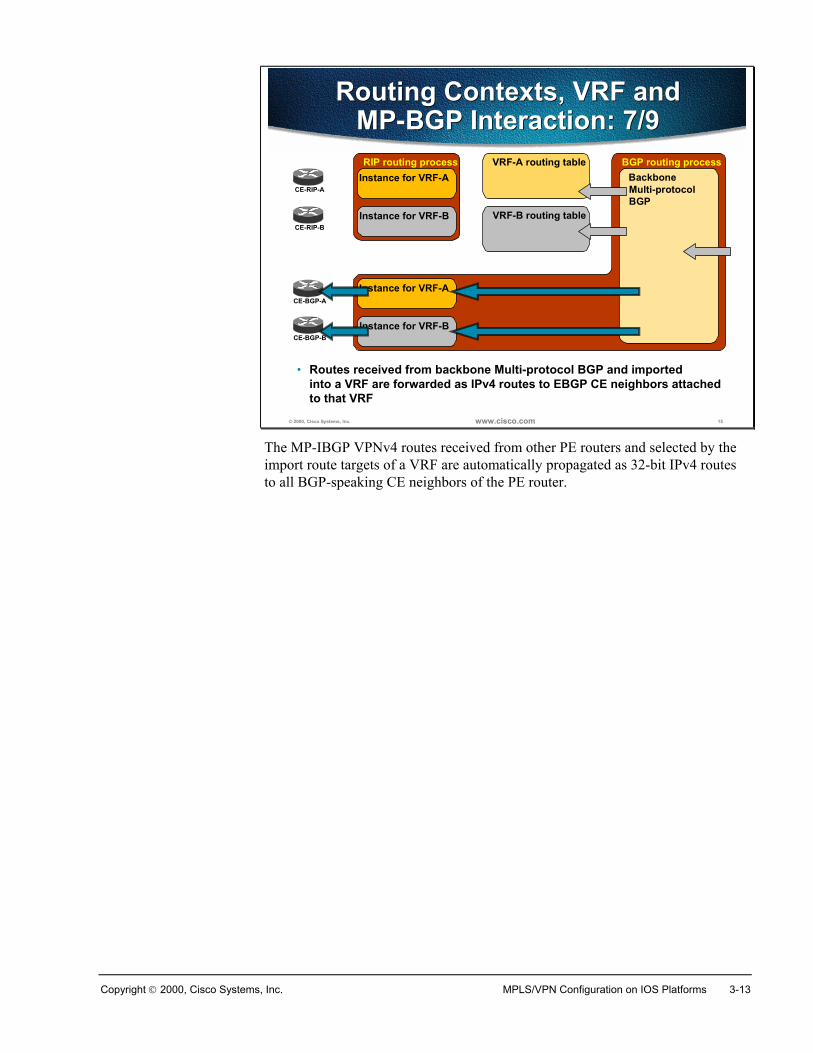
Copyright 2000, Cisco Systems, Inc. MPLS/VPN Configuration on IOS Platforms 3-13
© 2000, Cisco Systems, Inc. www.cisco.com 15
Routing Contexts, VRF andMP-BGP Interaction: 7/9
Routing Contexts, VRF andMP-BGP Interaction: 7/9
VRF-A routing tableRIP routing process
CE-RIP-AInstance for VRF-A
Instance for VRF-BCE-RIP-B
VRF-B routing table
BGP routing processBackboneMulti-protocol BGP
Instance for VRF-A
Instance for VRF-B
CE-BGP-A
CE-BGP-B
• Routes received from backbone Multi-protocol BGP and importedinto a VRF are forwarded as IPv4 routes to EBGP CE neighbors attached to that VRF
The MP-IBGP VPNv4 routes received from other PE routers and selected by theimport route targets of a VRF are automatically propagated as 32-bit IPv4 routesto all BGP-speaking CE neighbors of the PE router.
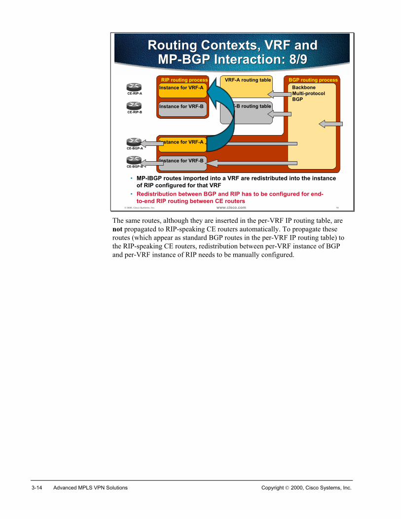
3-14 Advanced MPLS VPN Solutions Copyright 2000, Cisco Systems, Inc.
© 2000, Cisco Systems, Inc. www.cisco.com 16
Routing Contexts, VRF andMP-BGP Interaction: 8/9
Routing Contexts, VRF andMP-BGP Interaction: 8/9
VRF-A routing tableRIP routing process
CE-RIP-AInstance for VRF-A
Instance for VRF-BCE-RIP-B
VRF-B routing table
BGP routing processBackboneMulti-protocol BGP
Instance for VRF-A
Instance for VRF-B
CE-BGP-A
CE-BGP-B
• MP-IBGP routes imported into a VRF are redistributed into the instanceof RIP configured for that VRF
• Redistribution between BGP and RIP has to be configured for end-to-end RIP routing between CE routers
The same routes, although they are inserted in the per-VRF IP routing table, arenot propagated to RIP-speaking CE routers automatically. To propagate theseroutes (which appear as standard BGP routes in the per-VRF IP routing table) tothe RIP-speaking CE routers, redistribution between per-VRF instance of BGPand per-VRF instance of RIP needs to be manually configured.

Copyright 2000, Cisco Systems, Inc. MPLS/VPN Configuration on IOS Platforms 3-15
© 2000, Cisco Systems, Inc. www.cisco.com 17
Routing Contexts, VRF andMP-BGP Interaction: 9/9
Routing Contexts, VRF andMP-BGP Interaction: 9/9
VRF-A routing tableRIP routing process
CE-RIP-AInstance for VRF-A
Instance for VRF-BCE-RIP-B
VRF-B routing table
BGP routing processBackboneMulti-protocol BGP
Instance for VRF-A
Instance for VRF-B
CE-BGP-A
CE-BGP-B
• Routes redistributed from BGP into a VRF instance of RIP are sent toRIP-speaking CE routers
When the IBGP routes from the per-VRF IP routing table are successfullyredistributed into the per-VRF instance of RIP process, the RIP process announcesthese routes to RIP-speaking CE routers, thus achieving transparent end-to-endconnectivity between the CE routers.
3-16 Advanced MPLS VPN Solutions Copyright 2000, Cisco Systems, Inc.
SummaryMPLS/VPN enabled network separates the layer 3 routing task by splitting asingle physical router into a number of virtual routers. Router’s basic function isswitching packets between interfaces. Virtual routing and forwarding or VRF isused to create a virtual router that contains its own routing table, CEF cache andinterfaces.
To optimize performance a single BGP process or RIP process is used for allVRFs. A Route Distinguisher is used to distinguish between IP version 4 networksbelonging to different VPNs. We need, however, a separate OSPF process forevery VRF configured.
To send information from one CE router to another CE router an update is sentusing one of the supported routing protocols. The update is received by the PErouter that has to redistribute the information into BGP. The information istranslated into MP-BGP format where, upon export, a Route Target is added. Thisinformation is then sent to other PE routers where it is imported into VRFs that areusing the same Route Target. The other PE routers redistribute this informationinto the IGP used between the PE and the CE routers and send it to the CE routers.
Review Questions� Which data structures are associated with a VRF?
� How many interfaces can be associated with a VRF?
� How many VRFs can be associated with an interface?
� What is a routing protocol context?
� How are routing protocol contexts implemented in RIP?
� How are routing protocol contexts implemented in OSPF?
� How is a RIP route propagated into MP-BGP?
� When is a MP-BGP route inserted into a VRF?
Copyright 2000, Cisco Systems, Inc. MPLS/VPN Configuration on IOS Platforms 3-17
Configuring Virtual Routing and Forwarding Table
ObjectivesUpon completion of this section, you will be able to perform the following tasks:
� Create a Virtual Routing and Forwarding Table
� Specify Routing Distinguisher and Route Targets for the created VRF
� Associate interfaces with the VRF
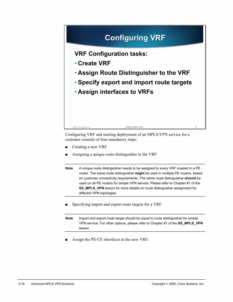
3-18 Advanced MPLS VPN Solutions Copyright 2000, Cisco Systems, Inc.
© 2000, Cisco Systems, Inc. www.cisco.com 22
Configuring VRFConfiguring VRF
VRF Configuration tasks:• Create VRF• Assign Route Distinguisher to the VRF• Specify export and import route targets• Assign interfaces to VRFs
Configuring VRF and starting deployment of an MPLS/VPN service for acustomer consists of four mandatory steps:
� Creating a new VRF
� Assigning a unique route distinguisher to the VRF
Note A unique route distinguisher needs to be assigned to every VRF created in a PErouter. The same route distinguisher might be used in multiple PE routers, basedon customer connectivity requirements. The same route distinguisher should beused on all PE routers for simple VPN service. Please refer to Chapter #1 of theSS_MPLS_VPN lesson for more details on route distinguisher assignment fordifferent VPN topologies.
� Specifying import and export route targets for a VRF
Note Import and export route target should be equal to route distinguisher for simpleVPN service. For other options, please refer to Chapter #1 of the SS_MPLS_VPNlesson.
� Assign the PE-CE interfaces to the new VRF.
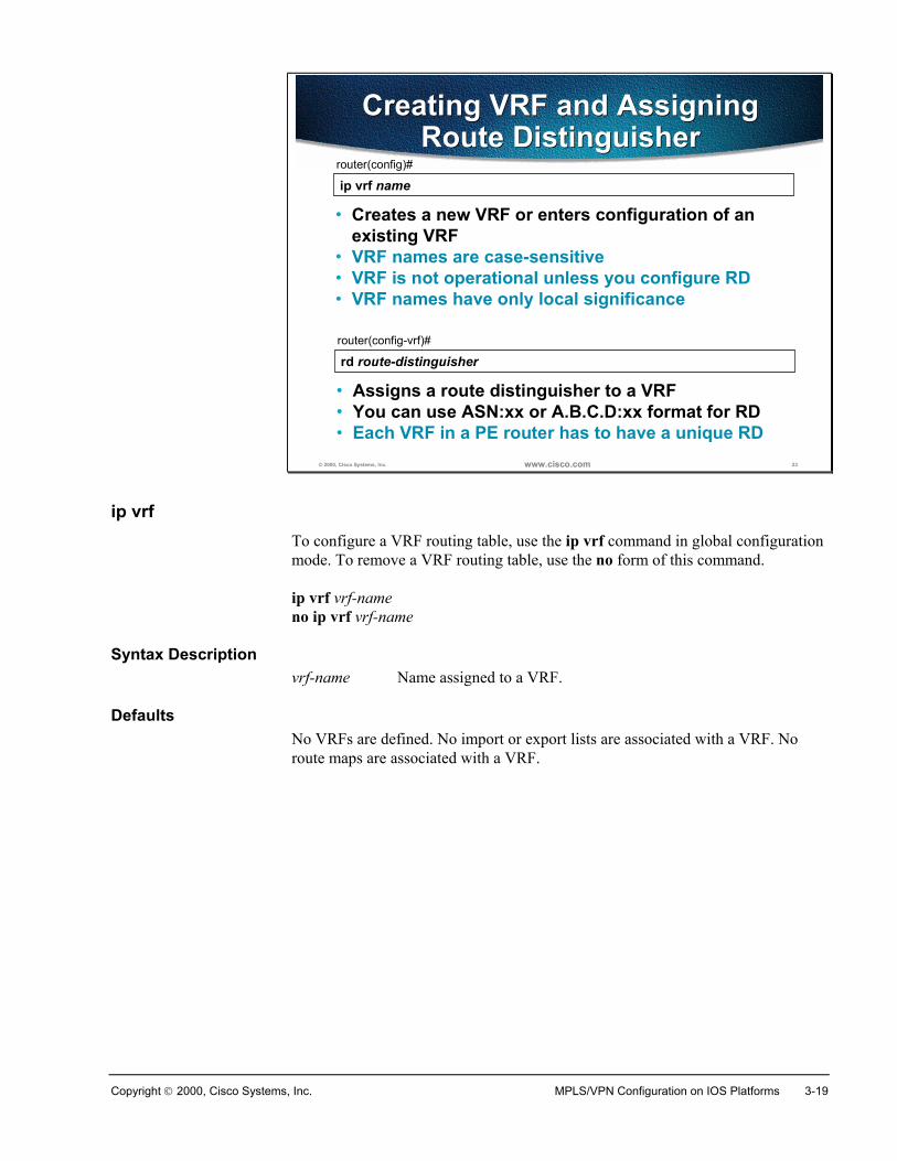
Copyright 2000, Cisco Systems, Inc. MPLS/VPN Configuration on IOS Platforms 3-19
© 2000, Cisco Systems, Inc. www.cisco.com 23
ip vrf namerouter(config)#
• Creates a new VRF or enters configuration of anexisting VRF
• VRF names are case-sensitive• VRF is not operational unless you configure RD• VRF names have only local significance
Creating VRF and AssigningRoute Distinguisher
Creating VRF and AssigningRoute Distinguisher
rd route-distinguisherrouter(config-vrf)#
• Assigns a route distinguisher to a VRF• You can use ASN:xx or A.B.C.D:xx format for RD• Each VRF in a PE router has to have a unique RD
ip vrfTo configure a VRF routing table, use the ip vrf command in global configurationmode. To remove a VRF routing table, use the no form of this command.
ip vrf vrf-nameno ip vrf vrf-name
Syntax Descriptionvrf-name Name assigned to a VRF.
DefaultsNo VRFs are defined. No import or export lists are associated with a VRF. Noroute maps are associated with a VRF.
3-20 Advanced MPLS VPN Solutions Copyright 2000, Cisco Systems, Inc.
rdTo create routing and forwarding tables for a VRF, use the rd command in VRFsubmode.
rd route-distinguisher
Syntax Descriptionroute-distinguisher Adds an 8-byte value to an IPv4 prefix to create a VPN
IPv4 prefix.
The route distinguisher can be specified in one of two formats:
� 16-bit AS-number followed by a 32-bit decimal number (AS:nn)
� 32-bit IP address followed by a 16-bit decimal number (A.B.C.D:nn)
DefaultsThere is no default. An RD must be configured for a VRF to be functional.
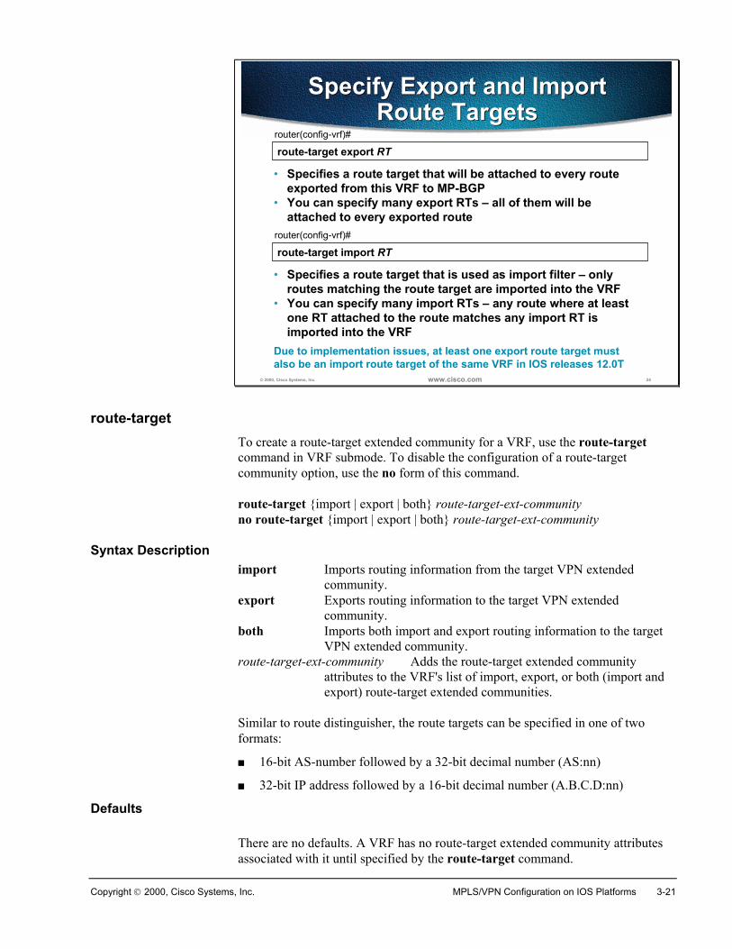
Copyright 2000, Cisco Systems, Inc. MPLS/VPN Configuration on IOS Platforms 3-21
© 2000, Cisco Systems, Inc. www.cisco.com 24
route-target export RTrouter(config-vrf)#
• Specifies a route target that will be attached to every routeexported from this VRF to MP-BGP
• You can specify many export RTs – all of them will beattached to every exported route
Specify Export and ImportRoute Targets
Specify Export and ImportRoute Targets
route-target import RTrouter(config-vrf)#
• Specifies a route target that is used as import filter – onlyroutes matching the route target are imported into the VRF
• You can specify many import RTs – any route where at leastone RT attached to the route matches any import RT isimported into the VRF
Due to implementation issues, at least one export route target must also be an import route target of the same VRF in IOS releases 12.0T
route-targetTo create a route-target extended community for a VRF, use the route-targetcommand in VRF submode. To disable the configuration of a route-targetcommunity option, use the no form of this command.
route-target {import | export | both} route-target-ext-communityno route-target {import | export | both} route-target-ext-community
Syntax Descriptionimport Imports routing information from the target VPN extended
community. export Exports routing information to the target VPN extended
community.both Imports both import and export routing information to the target
VPN extended community.route-target-ext-community Adds the route-target extended community
attributes to the VRF's list of import, export, or both (import andexport) route-target extended communities.
Similar to route distinguisher, the route targets can be specified in one of twoformats:
� 16-bit AS-number followed by a 32-bit decimal number (AS:nn)
� 32-bit IP address followed by a 16-bit decimal number (A.B.C.D:nn)
Defaults
There are no defaults. A VRF has no route-target extended community attributesassociated with it until specified by the route-target command.
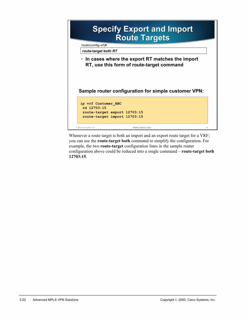
3-22 Advanced MPLS VPN Solutions Copyright 2000, Cisco Systems, Inc.
© 2000, Cisco Systems, Inc. www.cisco.com 25
route-target both RTrouter(config-vrf)#
• In cases where the export RT matches the importRT, use this form of route-target command
Specify Export and ImportRoute Targets
Specify Export and ImportRoute Targets
ip vrf Customer_ABC rd 12703:15 route-target export 12703:15 route-target import 12703:15
Sample router configuration for simple customer VPN:
Whenever a route target is both an import and an export route target for a VRF;you can use the route-target both command to simplify the configuration. Forexample, the two route-target configuration lines in the sample routerconfiguration above could be reduced into a single command – route-target both12703:15.
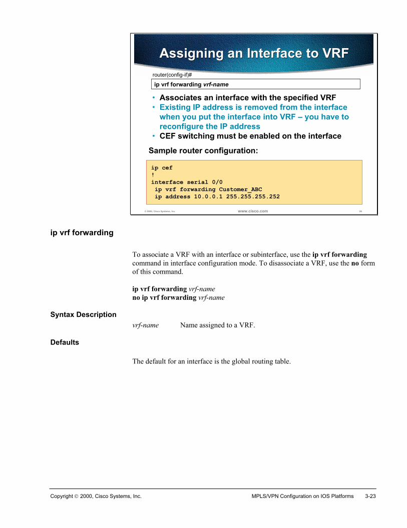
Copyright 2000, Cisco Systems, Inc. MPLS/VPN Configuration on IOS Platforms 3-23
© 2000, Cisco Systems, Inc. www.cisco.com 26
ip vrf forwarding vrf-namerouter(config-if)#
• Associates an interface with the specified VRF• Existing IP address is removed from the interface
when you put the interface into VRF – you have toreconfigure the IP address
• CEF switching must be enabled on the interface
Assigning an Interface to VRFAssigning an Interface to VRF
ip cef!interface serial 0/0 ip vrf forwarding Customer_ABC ip address 10.0.0.1 255.255.255.252
Sample router configuration:
ip vrf forwarding
To associate a VRF with an interface or subinterface, use the ip vrf forwardingcommand in interface configuration mode. To disassociate a VRF, use the no formof this command.
ip vrf forwarding vrf-nameno ip vrf forwarding vrf-name
Syntax Descriptionvrf-name Name assigned to a VRF.
Defaults
The default for an interface is the global routing table.
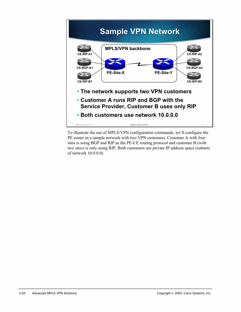
3-24 Advanced MPLS VPN Solutions Copyright 2000, Cisco Systems, Inc.
© 2000, Cisco Systems, Inc. www.cisco.com 27
Sample VPN NetworkSample VPN Network
• The network supports two VPN customers• Customer A runs RIP and BGP with the
Service Provider, Customer B uses only RIP• Both customers use network 10.0.0.0
MPLS/VPN backboneCE-RIP-A1
CE-BGP-A1PE-Site-X PE-Site-Y
CE-RIP-A2
CE-BGP-A2
CE-RIP-B1 CE-RIP-B2
To illustrate the use of MPLS/VPN configuration commands, we’ll configure thePE router in a sample network with two VPN customers. Customer A with foursites is using BGP and RIP as the PE-CE routing protocol and customer B (withtwo sites) is only using RIP. Both customers use private IP address space (subnetsof network 10.0.0.0)
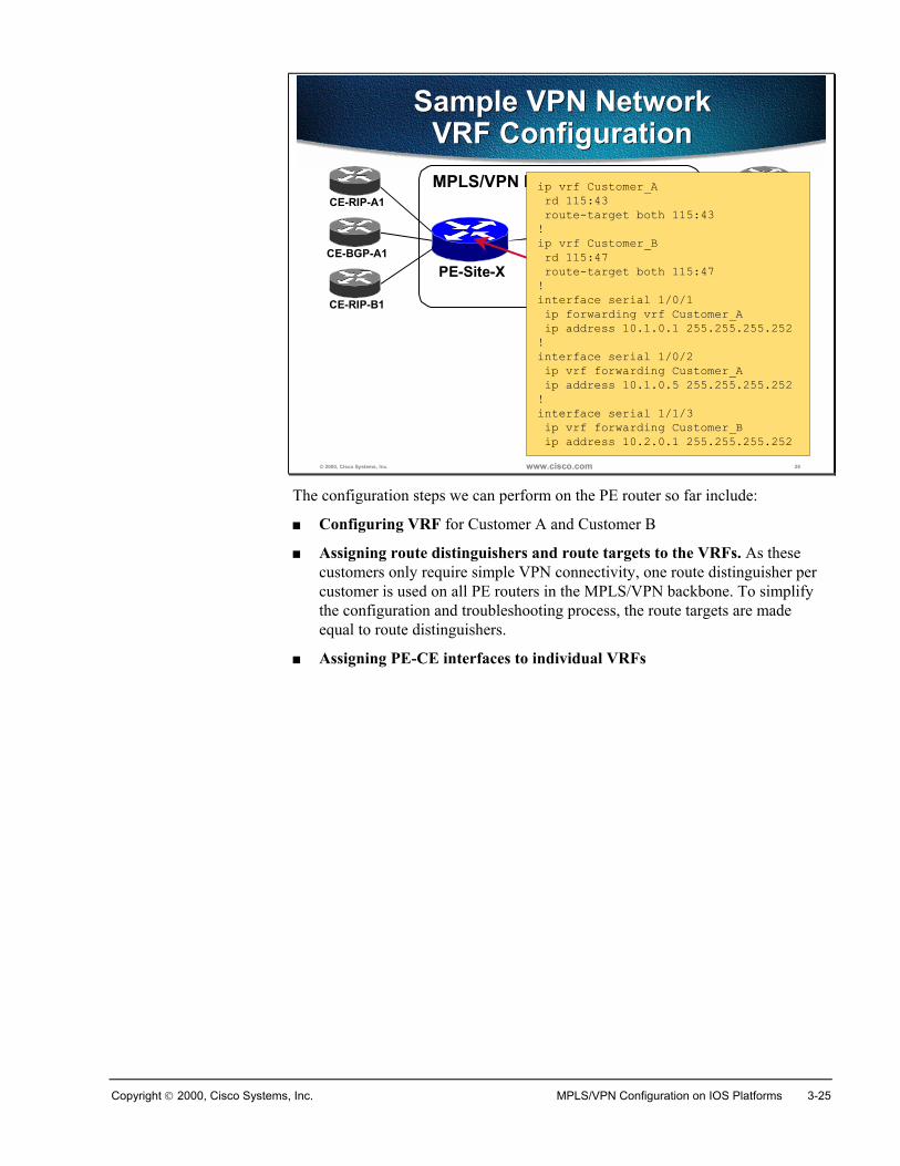
Copyright 2000, Cisco Systems, Inc. MPLS/VPN Configuration on IOS Platforms 3-25
© 2000, Cisco Systems, Inc. www.cisco.com 28
Sample VPN NetworkVRF Configuration
Sample VPN NetworkVRF ConfigurationMPLS/VPN backbone
CE-RIP-A1
CE-BGP-A1PE-Site-X PE-Site-Y
CE-RIP-A2
CE-BGP-A2
CE-RIP-B1 CE-RIP-B2
ip vrf Customer_A rd 115:43 route-target both 115:43!ip vrf Customer_B rd 115:47 route-target both 115:47!interface serial 1/0/1 ip forwarding vrf Customer_A ip address 10.1.0.1 255.255.255.252!interface serial 1/0/2 ip vrf forwarding Customer_A ip address 10.1.0.5 255.255.255.252!interface serial 1/1/3 ip vrf forwarding Customer_B ip address 10.2.0.1 255.255.255.252
The configuration steps we can perform on the PE router so far include:
� Configuring VRF for Customer A and Customer B
� Assigning route distinguishers and route targets to the VRFs. As thesecustomers only require simple VPN connectivity, one route distinguisher percustomer is used on all PE routers in the MPLS/VPN backbone. To simplifythe configuration and troubleshooting process, the route targets are madeequal to route distinguishers.
� Assigning PE-CE interfaces to individual VRFs
3-26 Advanced MPLS VPN Solutions Copyright 2000, Cisco Systems, Inc.
SummaryTo create a virtual router or a VRF use the ip vrf global command where the VRFis identified by a case-sensitive name.
Within the VRF configuration mode use the rd command to set the RouteDistinguisher.
If sites belonging to the same VPN are connected to different PE routers you haveto specify at least one Route Target extended community for import and export.Use the route-target import, route-target export or route-target bothcommands to set Route Target extended communities for import and export.
The last step in the configuration is specifying the interfaces that belong to thevirtual router. Use the ip forwarding vrf interface command to assign an interfaceto a VRF.
Review Questions� Which commands do you use to create a VRF?
� Which VRF parameters must be specified for a VRF to become operational?
� How do you associate an interface with a VRF?
� What happens to existing interface configuration when you associate theinterface with a VRF?
� How many formats can you use to specify RD and RT? What are theseformats?
� How many route targets can you configure on a VRF?
� How many import route targets have to match a route for the route to beimported into the VRF?
Copyright 2000, Cisco Systems, Inc. MPLS/VPN Configuration on IOS Platforms 3-27
Configuring a Multi-Protocol BGP SessionBetween the PE Routers
ObjectivesUpon completion of this section, you will be able to perform the following tasks:
� Configure BGP address families
� Configure MP-BGP neighbors
� Configure inter-AS MP-BGP neighbors
� Configure additional mandatory parameters on MP-BGP neighbors
� Configure propagation of standard and extended BGP communities
� Selectively enable IPv4 and MP-BGP sections between BGP neighbors
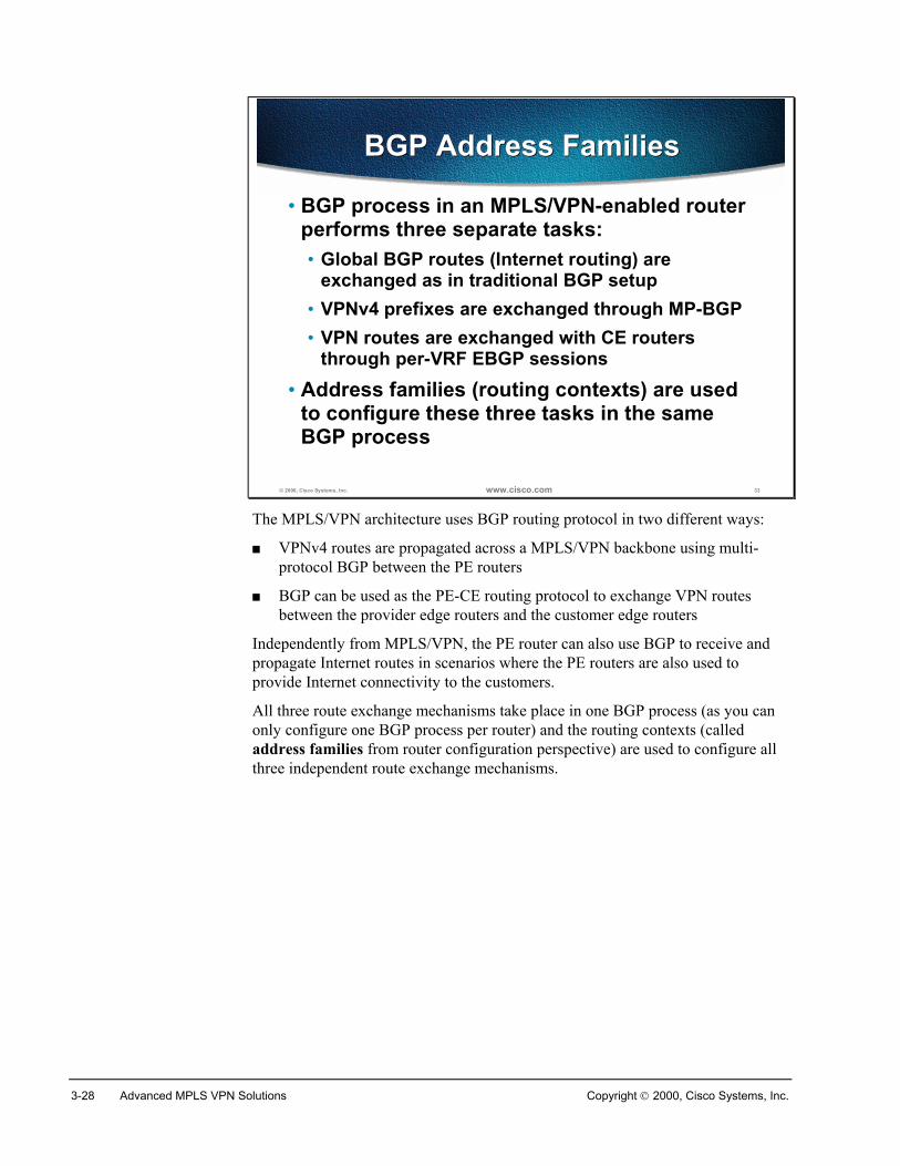
3-28 Advanced MPLS VPN Solutions Copyright 2000, Cisco Systems, Inc.
© 2000, Cisco Systems, Inc. www.cisco.com 33
BGP Address FamiliesBGP Address Families
• BGP process in an MPLS/VPN-enabled routerperforms three separate tasks:• Global BGP routes (Internet routing) are
exchanged as in traditional BGP setup• VPNv4 prefixes are exchanged through MP-BGP• VPN routes are exchanged with CE routers
through per-VRF EBGP sessions• Address families (routing contexts) are used
to configure these three tasks in the sameBGP process
The MPLS/VPN architecture uses BGP routing protocol in two different ways:
� VPNv4 routes are propagated across a MPLS/VPN backbone using multi-protocol BGP between the PE routers
� BGP can be used as the PE-CE routing protocol to exchange VPN routesbetween the provider edge routers and the customer edge routers
Independently from MPLS/VPN, the PE router can also use BGP to receive andpropagate Internet routes in scenarios where the PE routers are also used toprovide Internet connectivity to the customers.
All three route exchange mechanisms take place in one BGP process (as you canonly configure one BGP process per router) and the routing contexts (calledaddress families from router configuration perspective) are used to configure allthree independent route exchange mechanisms.
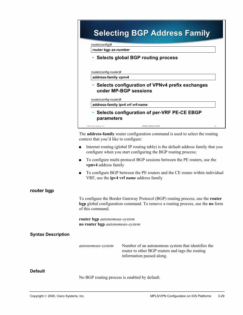
Copyright 2000, Cisco Systems, Inc. MPLS/VPN Configuration on IOS Platforms 3-29
© 2000, Cisco Systems, Inc. www.cisco.com 34
router bgp as-numberrouter(config)#
• Selects global BGP routing process
Selecting BGP Address FamilySelecting BGP Address Family
address-family vpnv4router(config-router)#
• Selects configuration of VPNv4 prefix exchangesunder MP-BGP sessions
address-family ipv4 vrf vrf-namerouter(config-router)#
• Selects configuration of per-VRF PE-CE EBGPparameters
The address-family router configuration command is used to select the routingcontext that you’d like to configure:
� Internet routing (global IP routing table) is the default address family that youconfigure when you start configuring the BGP routing process;
� To configure multi-protocol BGP sessions between the PE routers, use thevpnv4 address family
� To configure BGP between the PE routers and the CE routes within individualVRF, use the ipv4 vrf name address family
router bgpTo configure the Border Gateway Protocol (BGP) routing process, use the routerbgp global configuration command. To remove a routing process, use the no formof this command.
router bgp autonomous-systemno router bgp autonomous-system
Syntax Description
autonomous-system Number of an autonomous system that identifies therouter to other BGP routers and tags the routinginformation passed along.
DefaultNo BGP routing process is enabled by default.
3-30 Advanced MPLS VPN Solutions Copyright 2000, Cisco Systems, Inc.
address-familyTo enter the address family submode for configuring routing protocols, such asBGP, RIP and static routing, use the address-family command in address familyconfiguration submode. To disable the address family submode for configuringrouting protocols, use the no form of this command.
VPN-IPv4 unicast
address-family vpnv4 [unicast]no address-family vpnv4 [unicast]
IPv4 unicast
address-family ipv4 [unicast]no address-family ipv4 [unicast]
IPv4 unicast with CE router
address-family ipv4 [unicast] vrf vrf-nameno address-family ipv4 [unicast] vrf vrf-name
Syntax Descriptionipv4 Configures sessions that carry standard IPv4 address prefixes.vpnv4 Configures sessions that carry customer VPN-IPv4 prefixes, each
of which has been made globally unique by adding an 8-byteroute distinguisher.
unicast (Optional) Specifies unicast prefixes. vrf vrf-name Specifies the name of a VPN routing/forwarding instance (VRF)
to associate with submode commands.
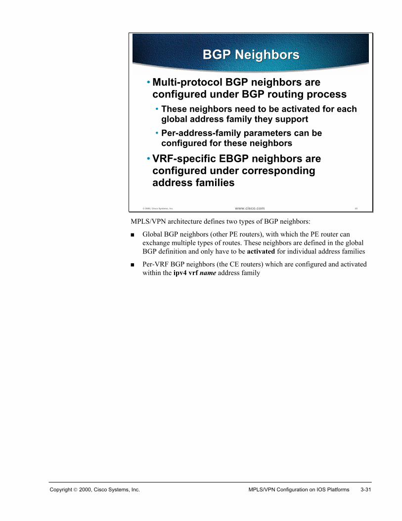
Copyright 2000, Cisco Systems, Inc. MPLS/VPN Configuration on IOS Platforms 3-31
© 2000, Cisco Systems, Inc. www.cisco.com 35
BGP NeighborsBGP Neighbors
• Multi-protocol BGP neighbors areconfigured under BGP routing process• These neighbors need to be activated for each
global address family they support• Per-address-family parameters can be
configured for these neighbors
• VRF-specific EBGP neighbors areconfigured under correspondingaddress families
MPLS/VPN architecture defines two types of BGP neighbors:
� Global BGP neighbors (other PE routers), with which the PE router canexchange multiple types of routes. These neighbors are defined in the globalBGP definition and only have to be activated for individual address families
� Per-VRF BGP neighbors (the CE routers) which are configured and activatedwithin the ipv4 vrf name address family
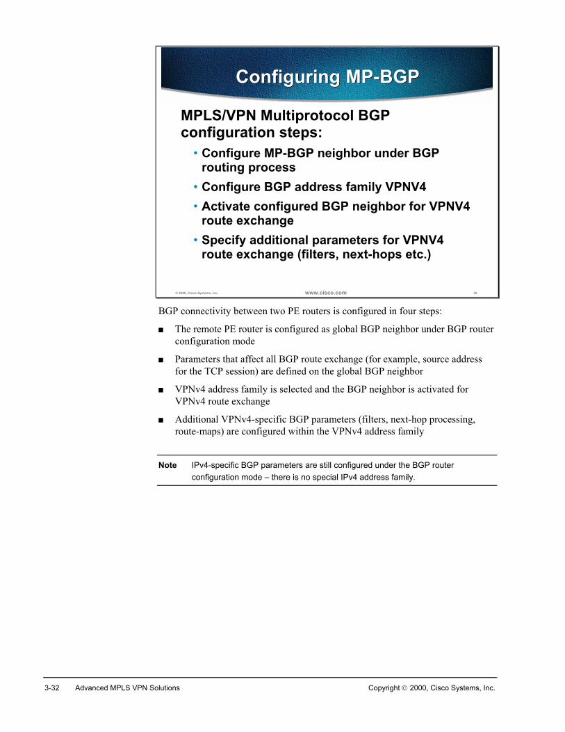
3-32 Advanced MPLS VPN Solutions Copyright 2000, Cisco Systems, Inc.
© 2000, Cisco Systems, Inc. www.cisco.com 36
Configuring MP-BGPConfiguring MP-BGP
MPLS/VPN Multiprotocol BGPconfiguration steps:
• Configure MP-BGP neighbor under BGProuting process
• Configure BGP address family VPNV4• Activate configured BGP neighbor for VPNV4
route exchange• Specify additional parameters for VPNV4
route exchange (filters, next-hops etc.)
BGP connectivity between two PE routers is configured in four steps:
� The remote PE router is configured as global BGP neighbor under BGP routerconfiguration mode
� Parameters that affect all BGP route exchange (for example, source addressfor the TCP session) are defined on the global BGP neighbor
� VPNv4 address family is selected and the BGP neighbor is activated forVPNv4 route exchange
� Additional VPNv4-specific BGP parameters (filters, next-hop processing,route-maps) are configured within the VPNv4 address family
Note IPv4-specific BGP parameters are still configured under the BGP routerconfiguration mode – there is no special IPv4 address family.
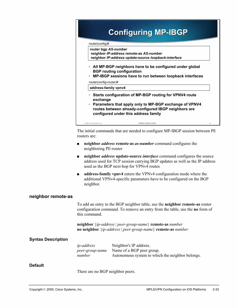
Copyright 2000, Cisco Systems, Inc. MPLS/VPN Configuration on IOS Platforms 3-33
© 2000, Cisco Systems, Inc. www.cisco.com 37
router bgp AS-number neighbor IP-address remote-as AS-number neighbor IP-address update-source loopback-interface
router(config)#
• All MP-BGP neighbors have to be configured under globalBGP routing configuration
• MP-IBGP sessions have to run between loopback interfaces
Configuring MP-IBGPConfiguring MP-IBGP
address-family vpnv4router(config-router)#
• Starts configuration of MP-BGP routing for VPNV4 routeexchange
• Parameters that apply only to MP-BGP exchange of VPNV4routes between already-configured IBGP neighbors areconfigured under this address family
The initial commands that are needed to configure MP-IBGP session between PErouters are:
� neighbor address remote-as as-number command configures theneighboring PE-router
� neighbor address update-source interface command configures the sourceaddress used for TCP session carrying BGP updates as well as the IP addressused as the BGP next-hop for VPNv4 routes
� address-family vpnv4 enters the VPNv4 configuration mode where theadditional VPNv4-specific parameters have to be configured on the BGPneighbor.
neighbor remote-asTo add an entry to the BGP neighbor table, use the neighbor remote-as routerconfiguration command. To remove an entry from the table, use the no form ofthis command.
neighbor {ip-address | peer-group-name} remote-as numberno neighbor {ip-address | peer-group-name} remote-as number
Syntax Descriptionip-address Neighbor's IP address.peer-group-name Name of a BGP peer group.number Autonomous system to which the neighbor belongs.
DefaultThere are no BGP neighbor peers.
3-34 Advanced MPLS VPN Solutions Copyright 2000, Cisco Systems, Inc.
neighbor update-source
To have the Cisco IOS software allow internal BGP sessions to use anyoperational interface for TCP connections, use the neighbor update-source routerconfiguration command. To restore the interface assignment to the closestinterface, which is called the best local address, use the no form of this command
neighbor {ip-address | peer-group-name} update-source interfaceno neighbor {ip-address | peer-group-name} update-source interface
Syntax Descriptionip-address IP address of the BGP-speaking neighbor.peer-group-name Name of a BGP peer group.interface Loopback interface.
DefaultBest local address
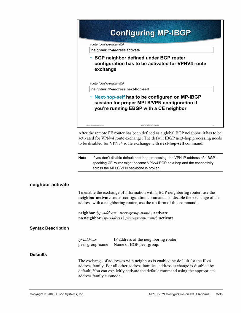
Copyright 2000, Cisco Systems, Inc. MPLS/VPN Configuration on IOS Platforms 3-35
© 2000, Cisco Systems, Inc. www.cisco.com 38
neighbor IP-address activaterouter(config-router-af)#
• BGP neighbor defined under BGP routerconfiguration has to be activated for VPNV4 routeexchange
Configuring MP-IBGPConfiguring MP-IBGP
neighbor IP-address next-hop-selfrouter(config-router-af)#
• Next-hop-self has to be configured on MP-IBGPsession for proper MPLS/VPN configuration ifyou’re running EBGP with a CE neighbor
After the remote PE router has been defined as a global BGP neighbor, it has to beactivated for VPNv4 route exchange. The default IBGP next-hop processing needsto be disabled for VPNv4 route exchange with next-hop-self command.
Note If you don’t disable default next-hop processing, the VPN IP address of a BGP-speaking CE router might become VPNv4 BGP next hop and the connectivityacross the MPLS/VPN backbone is broken.
neighbor activateTo enable the exchange of information with a BGP neighboring router, use theneighbor activate router configuration command. To disable the exchange of anaddress with a neighboring router, use the no form of this command.
neighbor {ip-address | peer-group-name} activateno neighbor {ip-address | peer-group-name} activate
Syntax Description
ip-address IP address of the neighboring router.peer-group-name Name of BGP peer group.
DefaultsThe exchange of addresses with neighbors is enabled by default for the IPv4address family. For all other address families, address exchange is disabled bydefault. You can explicitly activate the default command using the appropriateaddress family submode.
3-36 Advanced MPLS VPN Solutions Copyright 2000, Cisco Systems, Inc.
neighbor next-hop-self
To disable next-hop processing of BGP updates on the router, use the neighbornext-hop-self router configuration command. To disable this feature, use the noform of this command.
neighbor {ip-address | peer-group-name} next-hop-selfno neighbor {ip-address | peer-group-name} next-hop-self
Syntax Description
ip-address IP address of the BGP-speaking neighbor.peer-group-name Name of a BGP peer group.
Default
Disabled
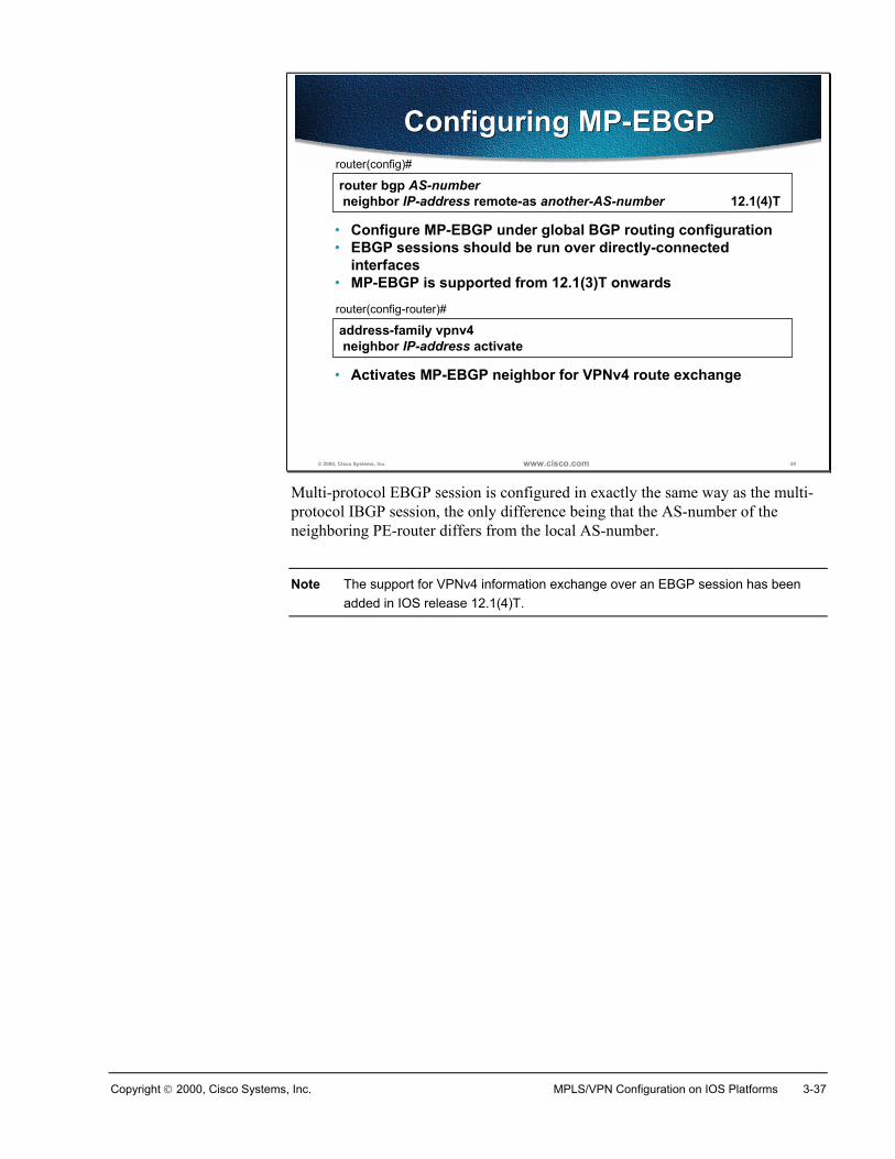
Copyright 2000, Cisco Systems, Inc. MPLS/VPN Configuration on IOS Platforms 3-37
© 2000, Cisco Systems, Inc. www.cisco.com 39
router bgp AS-number neighbor IP-address remote-as another-AS-number 12.1(4)T
router(config)#
• Configure MP-EBGP under global BGP routing configuration• EBGP sessions should be run over directly-connected
interfaces• MP-EBGP is supported from 12.1(3)T onwards
Configuring MP-EBGPConfiguring MP-EBGP
address-family vpnv4 neighbor IP-address activate
router(config-router)#
• Activates MP-EBGP neighbor for VPNv4 route exchange
Multi-protocol EBGP session is configured in exactly the same way as the multi-protocol IBGP session, the only difference being that the AS-number of theneighboring PE-router differs from the local AS-number.
Note The support for VPNv4 information exchange over an EBGP session has beenadded in IOS release 12.1(4)T.
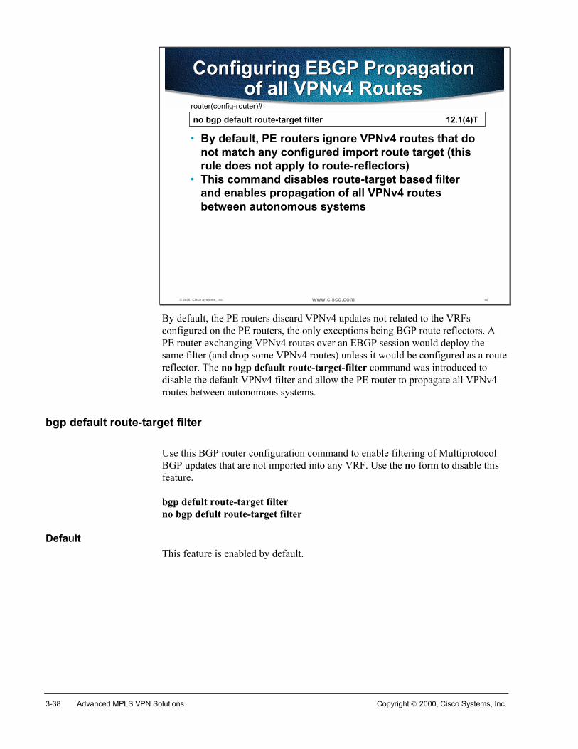
3-38 Advanced MPLS VPN Solutions Copyright 2000, Cisco Systems, Inc.
© 2000, Cisco Systems, Inc. www.cisco.com 40
no bgp default route-target filter 12.1(4)Trouter(config-router)#
• By default, PE routers ignore VPNv4 routes that donot match any configured import route target (thisrule does not apply to route-reflectors)
• This command disables route-target based filterand enables propagation of all VPNv4 routesbetween autonomous systems
Configuring EBGP Propagationof all VPNv4 Routes
Configuring EBGP Propagationof all VPNv4 Routes
By default, the PE routers discard VPNv4 updates not related to the VRFsconfigured on the PE routers, the only exceptions being BGP route reflectors. APE router exchanging VPNv4 routes over an EBGP session would deploy thesame filter (and drop some VPNv4 routes) unless it would be configured as a routereflector. The no bgp default route-target-filter command was introduced todisable the default VPNv4 filter and allow the PE router to propagate all VPNv4routes between autonomous systems.
bgp default route-target filter
Use this BGP router configuration command to enable filtering of MultiprotocolBGP updates that are not imported into any VRF. Use the no form to disable thisfeature.
bgp defult route-target filterno bgp defult route-target filter
DefaultThis feature is enabled by default.

Copyright 2000, Cisco Systems, Inc. MPLS/VPN Configuration on IOS Platforms 3-39
© 2000, Cisco Systems, Inc. www.cisco.com 41
neighbor IP-address send-community [extended | both] router(config-router-af)#
• This command configures propagation of standardand extended BGP communities attached to VPNv4prefixes
• Default value: only extended communities are sent
Usage guidelines:• Extended BGP communities attached to VPNv4
prefixes have to be exchanged between MP-BGPneighbors for proper MPLS/VPN operation
• To propagate standard BGP communities betweenMP-BGP neighbors, use the both option
Configuring MP-BGPBGP Community Propagation
Configuring MP-BGPBGP Community Propagation
MPLS/VPN architecture has introduced the extended community BGP attribute.BGP still supports the standard community attribute, which has not beensuperseded with the extended communities. The default community propagationbehavior for standard BGP communities has not changed – communitypropagation still needs to be configured manually. Extended BGP communities arepropagated by default, because their propagation is mandatory for successfulMPLS/VPN operation.
The neighbor send-community command was extended to support standard andextended communities. You should use this command to configure propagation ofstandard and extended communities if your BGP design relies on usage ofstandard communities (for example, to propagate Quality of Service informationacross the network).
neighbor send-community
To specify that a COMMUNITIES attribute should be sent to a BGP neighbor, usethe neighbor send-community router configuration command. To remove theentry, use the no form of this command.
neighbor {ip-address | peer-group-name} send-community [ extended | both ]no neighbor {ip-address | peer-group-name} send-community
Syntax Descriptionip-address Neighbor's IP address.peer-group-name Name of a BGP peer group.
DefaultNo COMMUNITIES attribute is sent to any neighbor.
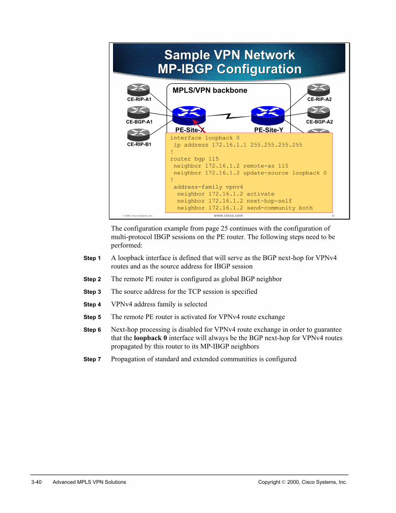
3-40 Advanced MPLS VPN Solutions Copyright 2000, Cisco Systems, Inc.
© 2000, Cisco Systems, Inc. www.cisco.com 42
Sample VPN NetworkMP-IBGP ConfigurationSample VPN Network
MP-IBGP ConfigurationMPLS/VPN backbone
CE-RIP-A1
CE-BGP-A1
PE-Site-X PE-Site-Y
CE-RIP-A2
CE-BGP-A2
CE-RIP-B1 CE-RIP-B2interface loopback 0 ip address 172.16.1.1 255.255.255.255!router bgp 115 neighbor 172.16.1.2 remote-as 115 neighbor 172.16.1.2 update-source loopback 0! address-family vpnv4 neighbor 172.16.1.2 activate neighbor 172.16.1.2 next-hop-self neighbor 172.16.1.2 send-community both
The configuration example from page 25 continues with the configuration ofmulti-protocol IBGP sessions on the PE router. The following steps need to beperformed:
Step 1 A loopback interface is defined that will serve as the BGP next-hop for VPNv4routes and as the source address for IBGP session
Step 2 The remote PE router is configured as global BGP neighbor
Step 3 The source address for the TCP session is specified
Step 4 VPNv4 address family is selected
Step 5 The remote PE router is activated for VPNv4 route exchange
Step 6 Next-hop processing is disabled for VPNv4 route exchange in order to guaranteethat the loopback 0 interface will always be the BGP next-hop for VPNv4 routespropagated by this router to its MP-IBGP neighbors
Step 7 Propagation of standard and extended communities is configured
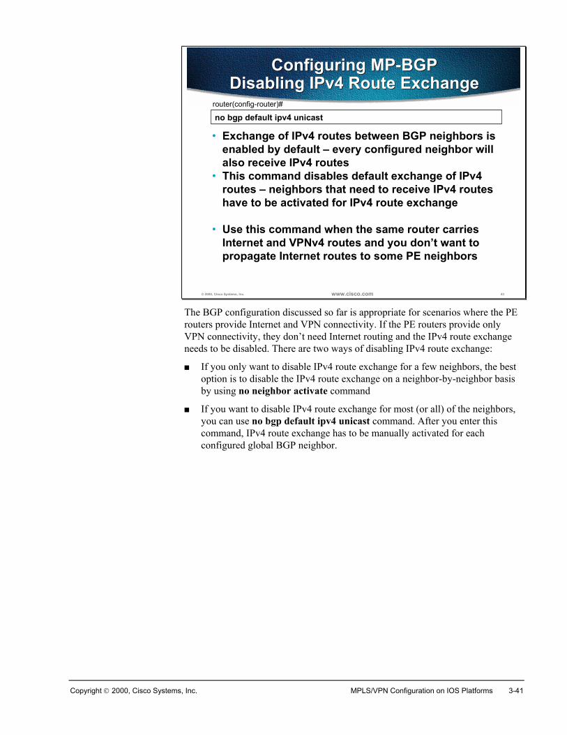
Copyright 2000, Cisco Systems, Inc. MPLS/VPN Configuration on IOS Platforms 3-41
© 2000, Cisco Systems, Inc. www.cisco.com 43
no bgp default ipv4 unicastrouter(config-router)#
• Exchange of IPv4 routes between BGP neighbors isenabled by default – every configured neighbor willalso receive IPv4 routes
• This command disables default exchange of IPv4routes – neighbors that need to receive IPv4 routeshave to be activated for IPv4 route exchange
• Use this command when the same router carriesInternet and VPNv4 routes and you don’t want topropagate Internet routes to some PE neighbors
Configuring MP-BGPDisabling IPv4 Route Exchange
Configuring MP-BGPDisabling IPv4 Route Exchange
The BGP configuration discussed so far is appropriate for scenarios where the PErouters provide Internet and VPN connectivity. If the PE routers provide onlyVPN connectivity, they don’t need Internet routing and the IPv4 route exchangeneeds to be disabled. There are two ways of disabling IPv4 route exchange:
� If you only want to disable IPv4 route exchange for a few neighbors, the bestoption is to disable the IPv4 route exchange on a neighbor-by-neighbor basisby using no neighbor activate command
� If you want to disable IPv4 route exchange for most (or all) of the neighbors,you can use no bgp default ipv4 unicast command. After you enter thiscommand, IPv4 route exchange has to be manually activated for eachconfigured global BGP neighbor.
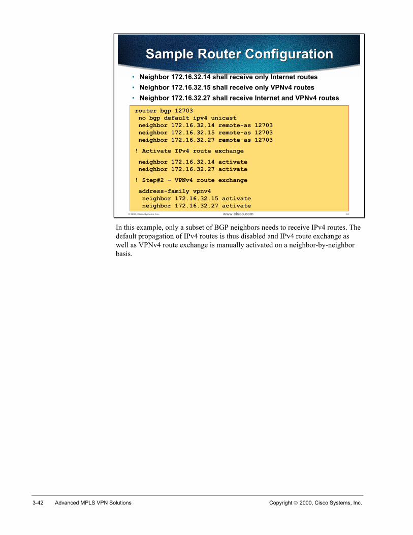
3-42 Advanced MPLS VPN Solutions Copyright 2000, Cisco Systems, Inc.
© 2000, Cisco Systems, Inc. www.cisco.com 44
Sample Router ConfigurationSample Router Configuration• Neighbor 172.16.32.14 shall receive only Internet routes• Neighbor 172.16.32.15 shall receive only VPNv4 routes• Neighbor 172.16.32.27 shall receive Internet and VPNv4 routes
router bgp 12703 no bgp default ipv4 unicast neighbor 172.16.32.14 remote-as 12703 neighbor 172.16.32.15 remote-as 12703 neighbor 172.16.32.27 remote-as 12703! Activate IPv4 route exchange neighbor 172.16.32.14 activate neighbor 172.16.32.27 activate! Step#2 – VPNv4 route exchange address-family vpnv4 neighbor 172.16.32.15 activate neighbor 172.16.32.27 activate
In this example, only a subset of BGP neighbors needs to receive IPv4 routes. Thedefault propagation of IPv4 routes is thus disabled and IPv4 route exchange aswell as VPNv4 route exchange is manually activated on a neighbor-by-neighborbasis.
Copyright 2000, Cisco Systems, Inc. MPLS/VPN Configuration on IOS Platforms 3-43
SummaryMP-BGP is used to propagate VPN specific information between PE routers.Standard BGP version 4 can also be used with the CE routers. Address familiesare used to tell the BGP process which routing table to use to find neighbor andwhere to put the received updates. There is a separate address family for each VRFand one address family for VPN-IPv4 updates.
Other PE routers are configured as standard BGP neighbors in the global part ofthe BGP configuration and have to be activated in the vpn_ipv4 address family.
Extended communities are propagated while standard communities are not. Usethe neighbor neighbor send-community command to change the default.
You should use the neighbor neighbor next-hop-self command to make sure thePE loopbacks are used as the next hop address.
Review Questions� What is a BGP address family?
� How many BGP address families do you have to configure on a PE router?
� In which address family is the MP-IBGP neighbor configured?
� Which are the mandatory parameters that you have to configure on MP-BGPneighbor?
� Which additional parameters have to be configured to support MP-EBGPneighbors?
� How do you enable community propagation for VPNv4 MP-BGP sessions?
� Why would you want to disable propagation of IPv4 routing updates betweenMP-BGP neighbors?
� How is the propagation of IPv4 routing updates between MP-BGP neighborsdisabled?
3-44 Advanced MPLS VPN Solutions Copyright 2000, Cisco Systems, Inc.
Configuring Routing Protocols Between PE and CERouters
ObjectivesUpon completion of this section, you will be able to perform the following tasks:
� Configure VRF address families in routing protocols
� Configure per-VRF BGP parameters
� Configure static routes within a VRF
� Configure per-VRF OSPF process
� Propagate RIP, OSPF, and static routes across a MP-BGP backbone
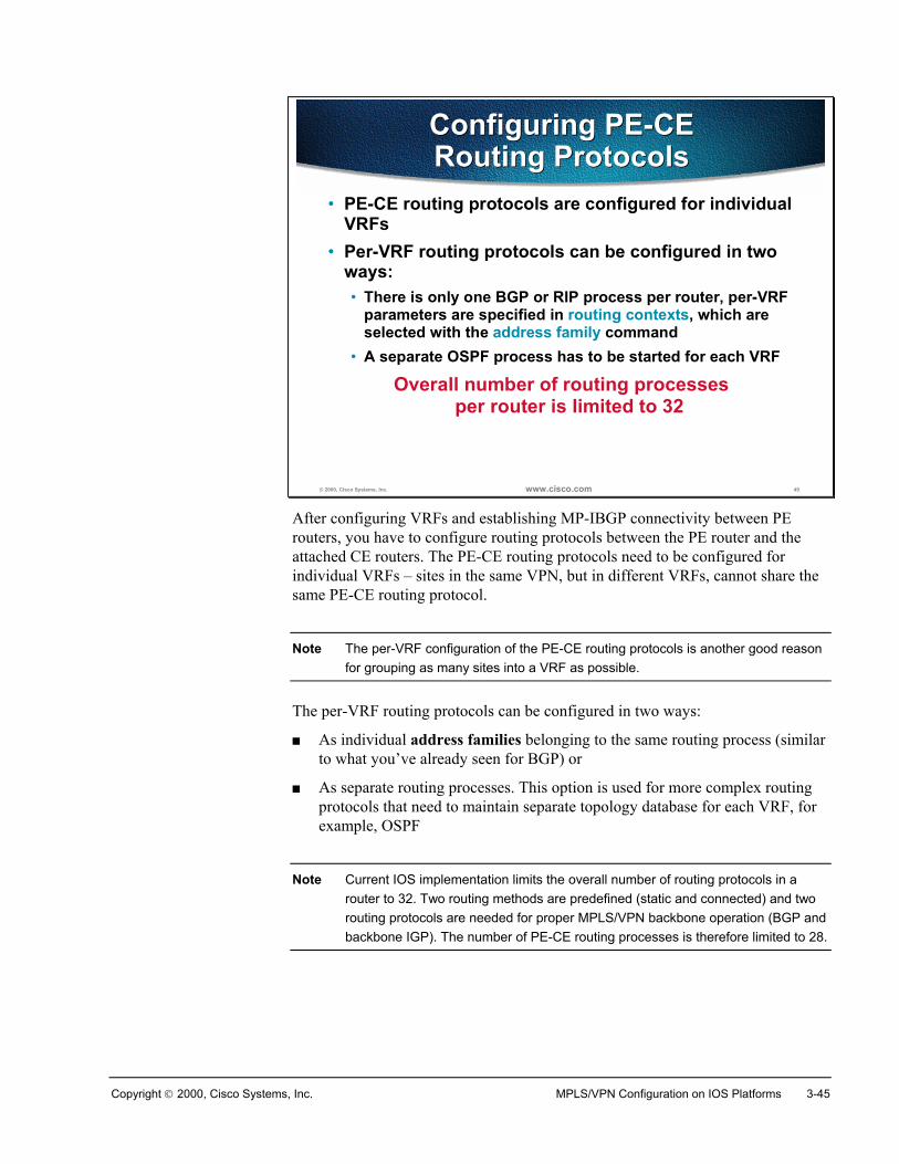
Copyright 2000, Cisco Systems, Inc. MPLS/VPN Configuration on IOS Platforms 3-45
© 2000, Cisco Systems, Inc. www.cisco.com 49
Configuring PE-CERouting ProtocolsConfiguring PE-CERouting Protocols
• PE-CE routing protocols are configured for individualVRFs
• Per-VRF routing protocols can be configured in twoways:• There is only one BGP or RIP process per router, per-VRF
parameters are specified in routing contexts, which areselected with the address family command
• A separate OSPF process has to be started for each VRF
Overall number of routing processesper router is limited to 32
After configuring VRFs and establishing MP-IBGP connectivity between PErouters, you have to configure routing protocols between the PE router and theattached CE routers. The PE-CE routing protocols need to be configured forindividual VRFs – sites in the same VPN, but in different VRFs, cannot share thesame PE-CE routing protocol.
Note The per-VRF configuration of the PE-CE routing protocols is another good reasonfor grouping as many sites into a VRF as possible.
The per-VRF routing protocols can be configured in two ways:
� As individual address families belonging to the same routing process (similarto what you’ve already seen for BGP) or
� As separate routing processes. This option is used for more complex routingprotocols that need to maintain separate topology database for each VRF, forexample, OSPF
Note Current IOS implementation limits the overall number of routing protocols in arouter to 32. Two routing methods are predefined (static and connected) and tworouting protocols are needed for proper MPLS/VPN backbone operation (BGP andbackbone IGP). The number of PE-CE routing processes is therefore limited to 28.
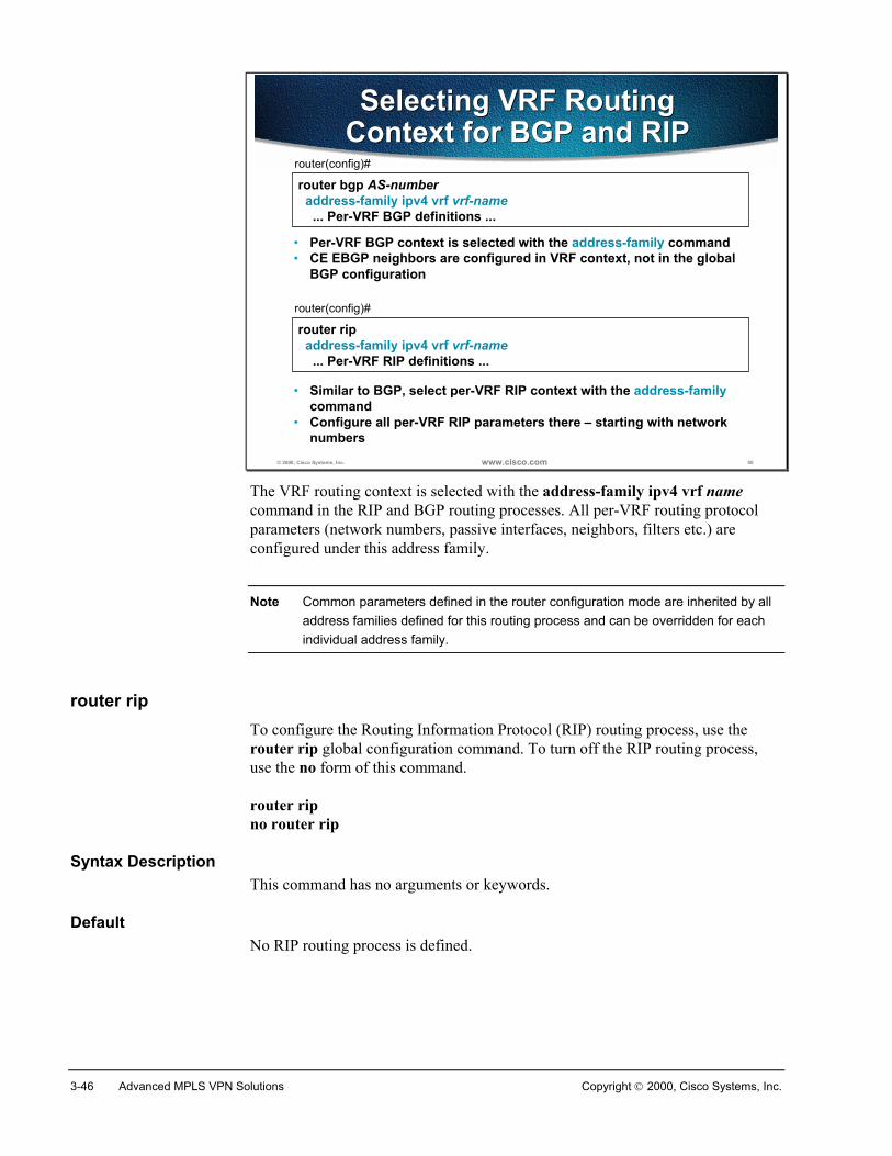
3-46 Advanced MPLS VPN Solutions Copyright 2000, Cisco Systems, Inc.
© 2000, Cisco Systems, Inc. www.cisco.com 50
router bgp AS-number address-family ipv4 vrf vrf-name ... Per-VRF BGP definitions ...
router(config)#
• Per-VRF BGP context is selected with the address-family command• CE EBGP neighbors are configured in VRF context, not in the global
BGP configuration
Selecting VRF RoutingContext for BGP and RIPSelecting VRF Routing
Context for BGP and RIP
router rip address-family ipv4 vrf vrf-name ... Per-VRF RIP definitions ...
router(config)#
• Similar to BGP, select per-VRF RIP context with the address-familycommand
• Configure all per-VRF RIP parameters there – starting with networknumbers
The VRF routing context is selected with the address-family ipv4 vrf namecommand in the RIP and BGP routing processes. All per-VRF routing protocolparameters (network numbers, passive interfaces, neighbors, filters etc.) areconfigured under this address family.
Note Common parameters defined in the router configuration mode are inherited by alladdress families defined for this routing process and can be overridden for eachindividual address family.
router ripTo configure the Routing Information Protocol (RIP) routing process, use therouter rip global configuration command. To turn off the RIP routing process,use the no form of this command.
router ripno router rip
Syntax DescriptionThis command has no arguments or keywords.
DefaultNo RIP routing process is defined.
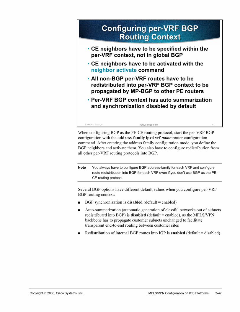
Copyright 2000, Cisco Systems, Inc. MPLS/VPN Configuration on IOS Platforms 3-47
© 2000, Cisco Systems, Inc. www.cisco.com 51
Configuring per-VRF BGPRouting Context
Configuring per-VRF BGPRouting Context
• CE neighbors have to be specified within theper-VRF context, not in global BGP
• CE neighbors have to be activated with theneighbor activate command
• All non-BGP per-VRF routes have to beredistributed into per-VRF BGP context to bepropagated by MP-BGP to other PE routers
• Per-VRF BGP context has auto summarizationand synchronization disabled by default
When configuring BGP as the PE-CE routing protocol, start the per-VRF BGPconfiguration with the address-family ipv4 vrf name router configurationcommand. After entering the address family configuration mode, you define theBGP neighbors and activate them. You also have to configure redistribution fromall other per-VRF routing protocols into BGP.
Note You always have to configure BGP address-family for each VRF and configureroute redistribution into BGP for each VRF even if you don’t use BGP as the PE-CE routing protocol
Several BGP options have different default values when you configure per-VRFBGP routing context:
� BGP synchronization is disabled (default = enabled)
� Auto-summarization (automatic generation of classful networks out of subnetsredistributed into BGP) is disabled (default = enabled), as the MPLS/VPNbackbone has to propagate customer subnets unchanged to facilitatetransparent end-to-end routing between customer sites
� Redistribution of internal BGP routes into IGP is enabled (default = disabled)
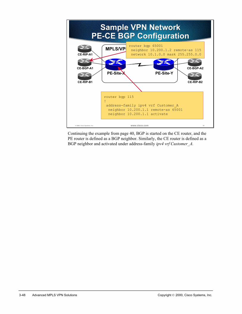
3-48 Advanced MPLS VPN Solutions Copyright 2000, Cisco Systems, Inc.
© 2000, Cisco Systems, Inc. www.cisco.com 52
Sample VPN NetworkPE-CE BGP Configuration
Sample VPN NetworkPE-CE BGP Configuration
MPLS/VPN backboneCE-RIP-A1
CE-BGP-A1PE-Site-X PE-Site-Y
CE-RIP-A2
CE-BGP-A2
CE-RIP-B1 CE-RIP-B2
router bgp 115! address-family ipv4 vrf Customer_A neighbor 10.200.1.1 remote-as 65001 neighbor 10.200.1.1 activate
router bgp 65001 neighbor 10.200.1.2 remote-as 115 network 10.1.0.0 mask 255.255.0.0
Continuing the example from page 40, BGP is started on the CE router, and thePE router is defined as a BGP neighbor. Similarly, the CE router is defined as aBGP neighbor and activated under address-family ipv4 vrf Customer_A.
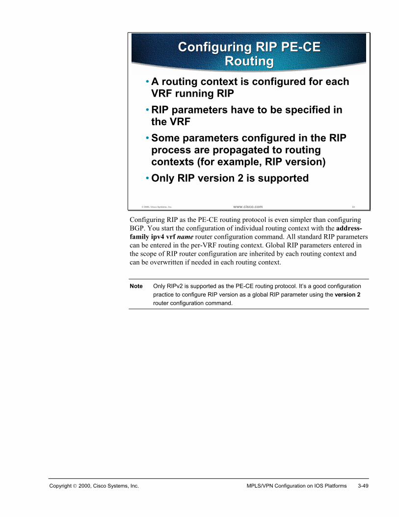
Copyright 2000, Cisco Systems, Inc. MPLS/VPN Configuration on IOS Platforms 3-49
© 2000, Cisco Systems, Inc. www.cisco.com 53
Configuring RIP PE-CERouting
Configuring RIP PE-CERouting
• A routing context is configured for eachVRF running RIP
• RIP parameters have to be specified inthe VRF
• Some parameters configured in the RIPprocess are propagated to routingcontexts (for example, RIP version)
• Only RIP version 2 is supported
Configuring RIP as the PE-CE routing protocol is even simpler than configuringBGP. You start the configuration of individual routing context with the address-family ipv4 vrf name router configuration command. All standard RIP parameterscan be entered in the per-VRF routing context. Global RIP parameters entered inthe scope of RIP router configuration are inherited by each routing context andcan be overwritten if needed in each routing context.
Note Only RIPv2 is supported as the PE-CE routing protocol. It’s a good configurationpractice to configure RIP version as a global RIP parameter using the version 2router configuration command.
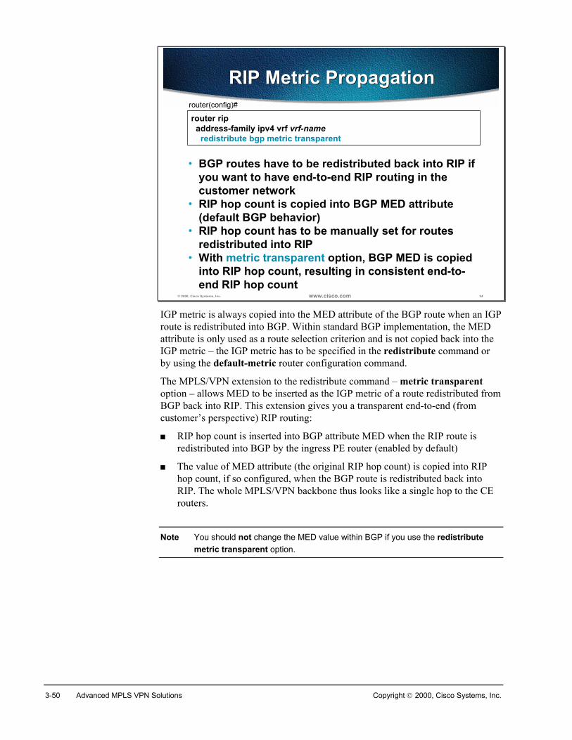
3-50 Advanced MPLS VPN Solutions Copyright 2000, Cisco Systems, Inc.
© 2000, Cisco Systems, Inc. www.cisco.com 54
router rip address-family ipv4 vrf vrf-name redistribute bgp metric transparent
router(config)#
• BGP routes have to be redistributed back into RIP ifyou want to have end-to-end RIP routing in thecustomer network
• RIP hop count is copied into BGP MED attribute(default BGP behavior)
• RIP hop count has to be manually set for routesredistributed into RIP
• With metric transparent option, BGP MED is copiedinto RIP hop count, resulting in consistent end-to-end RIP hop count
RIP Metric PropagationRIP Metric Propagation
IGP metric is always copied into the MED attribute of the BGP route when an IGProute is redistributed into BGP. Within standard BGP implementation, the MEDattribute is only used as a route selection criterion and is not copied back into theIGP metric – the IGP metric has to be specified in the redistribute command orby using the default-metric router configuration command.
The MPLS/VPN extension to the redistribute command – metric transparentoption – allows MED to be inserted as the IGP metric of a route redistributed fromBGP back into RIP. This extension gives you a transparent end-to-end (fromcustomer’s perspective) RIP routing:
� RIP hop count is inserted into BGP attribute MED when the RIP route isredistributed into BGP by the ingress PE router (enabled by default)
� The value of MED attribute (the original RIP hop count) is copied into RIPhop count, if so configured, when the BGP route is redistributed back intoRIP. The whole MPLS/VPN backbone thus looks like a single hop to the CErouters.
Note You should not change the MED value within BGP if you use the redistributemetric transparent option.
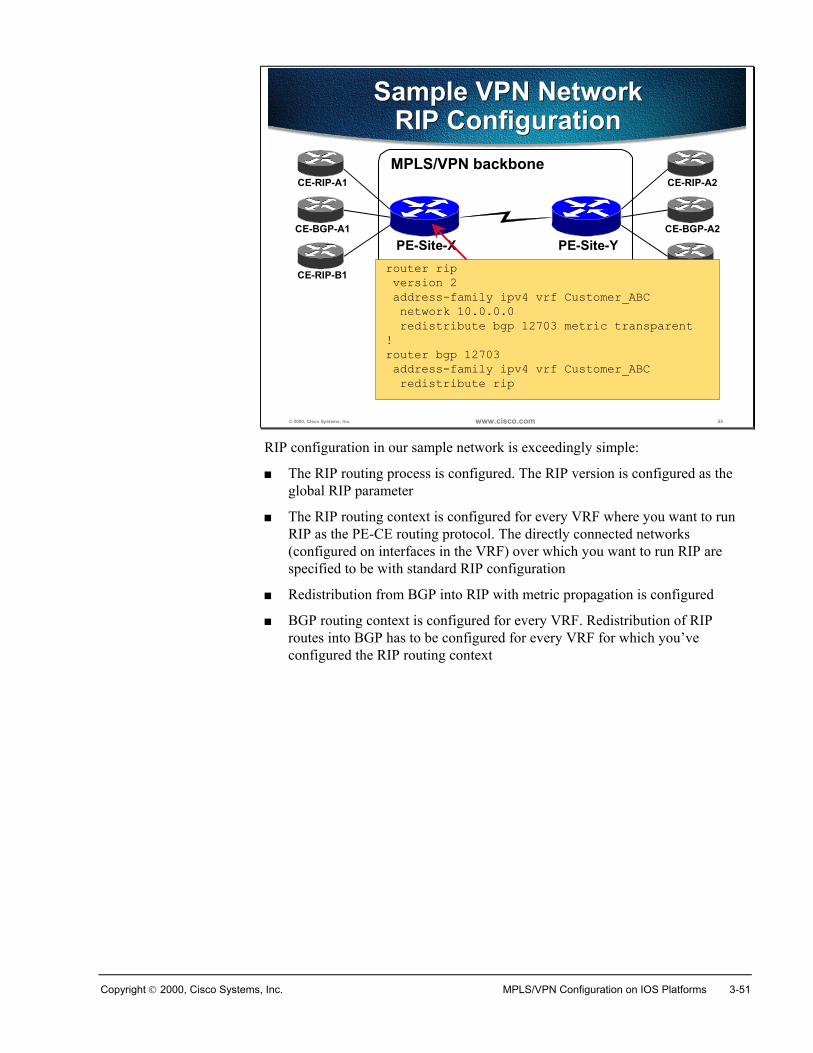
Copyright 2000, Cisco Systems, Inc. MPLS/VPN Configuration on IOS Platforms 3-51
© 2000, Cisco Systems, Inc. www.cisco.com 55
Sample VPN NetworkRIP Configuration
Sample VPN NetworkRIP ConfigurationMPLS/VPN backbone
CE-RIP-A1
CE-BGP-A1PE-Site-X PE-Site-Y
CE-RIP-A2
CE-BGP-A2
CE-RIP-B1 CE-RIP-B2router rip version 2 address-family ipv4 vrf Customer_ABC network 10.0.0.0 redistribute bgp 12703 metric transparent!router bgp 12703 address-family ipv4 vrf Customer_ABC redistribute rip
RIP configuration in our sample network is exceedingly simple:
� The RIP routing process is configured. The RIP version is configured as theglobal RIP parameter
� The RIP routing context is configured for every VRF where you want to runRIP as the PE-CE routing protocol. The directly connected networks(configured on interfaces in the VRF) over which you want to run RIP arespecified to be with standard RIP configuration
� Redistribution from BGP into RIP with metric propagation is configured
� BGP routing context is configured for every VRF. Redistribution of RIProutes into BGP has to be configured for every VRF for which you’veconfigured the RIP routing context
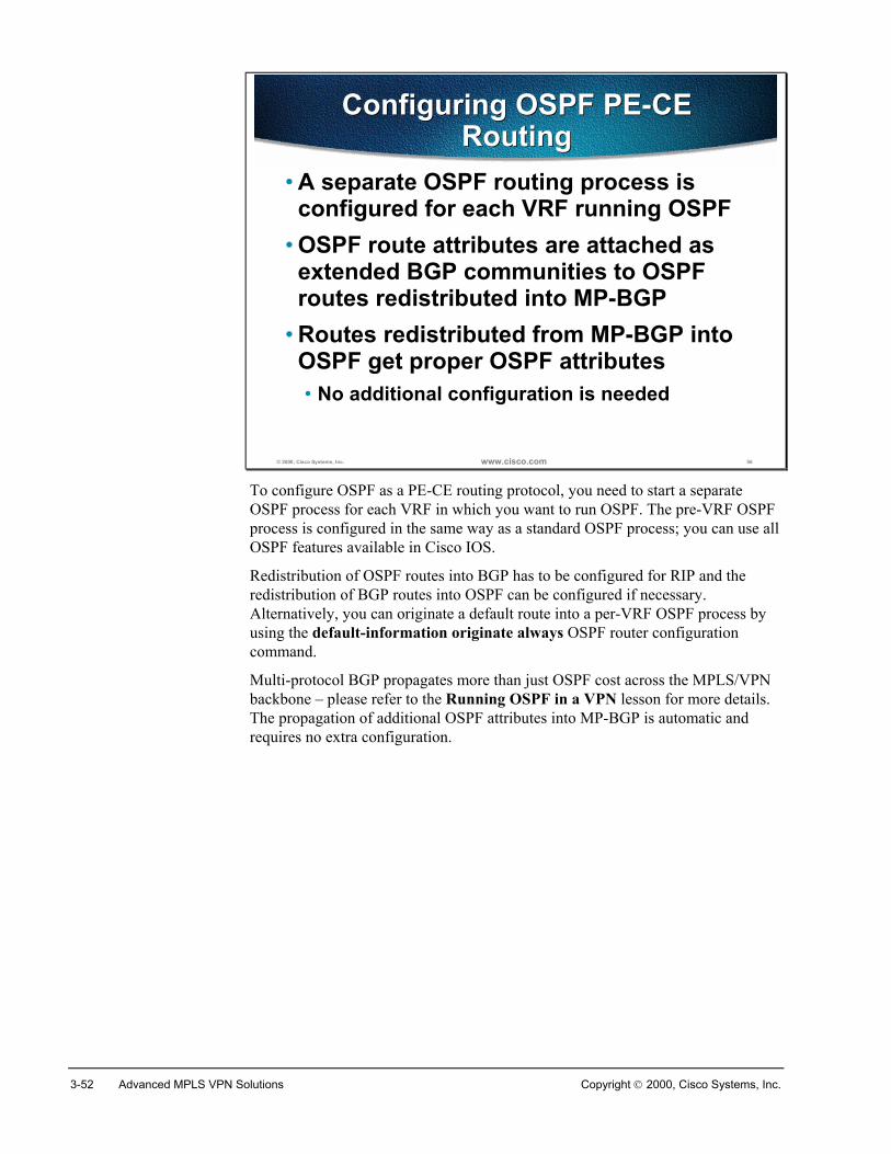
3-52 Advanced MPLS VPN Solutions Copyright 2000, Cisco Systems, Inc.
© 2000, Cisco Systems, Inc. www.cisco.com 56
Configuring OSPF PE-CERouting
Configuring OSPF PE-CERouting
• A separate OSPF routing process isconfigured for each VRF running OSPF
• OSPF route attributes are attached asextended BGP communities to OSPFroutes redistributed into MP-BGP
• Routes redistributed from MP-BGP intoOSPF get proper OSPF attributes• No additional configuration is needed
To configure OSPF as a PE-CE routing protocol, you need to start a separateOSPF process for each VRF in which you want to run OSPF. The pre-VRF OSPFprocess is configured in the same way as a standard OSPF process; you can use allOSPF features available in Cisco IOS.
Redistribution of OSPF routes into BGP has to be configured for RIP and theredistribution of BGP routes into OSPF can be configured if necessary.Alternatively, you can originate a default route into a per-VRF OSPF process byusing the default-information originate always OSPF router configurationcommand.
Multi-protocol BGP propagates more than just OSPF cost across the MPLS/VPNbackbone – please refer to the Running OSPF in a VPN lesson for more details.The propagation of additional OSPF attributes into MP-BGP is automatic andrequires no extra configuration.
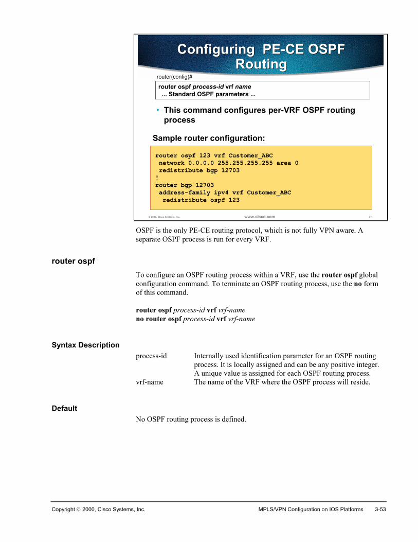
Copyright 2000, Cisco Systems, Inc. MPLS/VPN Configuration on IOS Platforms 3-53
© 2000, Cisco Systems, Inc. www.cisco.com 57
router ospf process-id vrf name ... Standard OSPF parameters ...
router(config)#
• This command configures per-VRF OSPF routingprocess
Configuring PE-CE OSPFRouting
Configuring PE-CE OSPFRouting
router ospf 123 vrf Customer_ABC network 0.0.0.0 255.255.255.255 area 0 redistribute bgp 12703!router bgp 12703 address-family ipv4 vrf Customer_ABC redistribute ospf 123
Sample router configuration:
OSPF is the only PE-CE routing protocol, which is not fully VPN aware. Aseparate OSPF process is run for every VRF.
router ospfTo configure an OSPF routing process within a VRF, use the router ospf globalconfiguration command. To terminate an OSPF routing process, use the no formof this command.
router ospf process-id vrf vrf-nameno router ospf process-id vrf vrf-name
Syntax Descriptionprocess-id Internally used identification parameter for an OSPF routing
process. It is locally assigned and can be any positive integer.A unique value is assigned for each OSPF routing process.
vrf-name The name of the VRF where the OSPF process will reside.
DefaultNo OSPF routing process is defined.
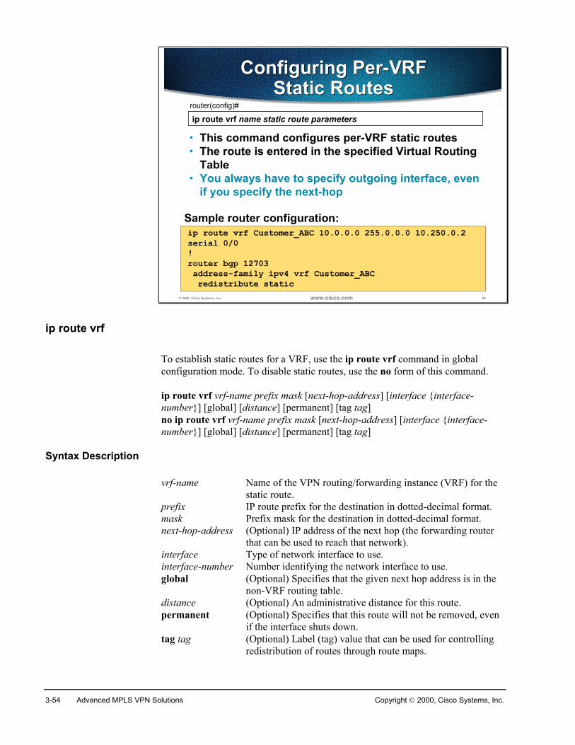
3-54 Advanced MPLS VPN Solutions Copyright 2000, Cisco Systems, Inc.
© 2000, Cisco Systems, Inc. www.cisco.com 58
ip route vrf name static route parametersrouter(config)#
• This command configures per-VRF static routes• The route is entered in the specified Virtual Routing
Table• You always have to specify outgoing interface, even
if you specify the next-hop
Configuring Per-VRFStatic Routes
Configuring Per-VRFStatic Routes
ip route vrf Customer_ABC 10.0.0.0 255.0.0.0 10.250.0.2serial 0/0!router bgp 12703 address-family ipv4 vrf Customer_ABC redistribute static
Sample router configuration:
ip route vrf
To establish static routes for a VRF, use the ip route vrf command in globalconfiguration mode. To disable static routes, use the no form of this command.
ip route vrf vrf-name prefix mask [next-hop-address] [interface {interface-number}] [global] [distance] [permanent] [tag tag]no ip route vrf vrf-name prefix mask [next-hop-address] [interface {interface-number}] [global] [distance] [permanent] [tag tag]
Syntax Description
vrf-name Name of the VPN routing/forwarding instance (VRF) for thestatic route.
prefix IP route prefix for the destination in dotted-decimal format.mask Prefix mask for the destination in dotted-decimal format.next-hop-address (Optional) IP address of the next hop (the forwarding router
that can be used to reach that network).interface Type of network interface to use. interface-number Number identifying the network interface to use.global (Optional) Specifies that the given next hop address is in the
non-VRF routing table. distance (Optional) An administrative distance for this route.permanent (Optional) Specifies that this route will not be removed, even
if the interface shuts down.tag tag (Optional) Label (tag) value that can be used for controlling
redistribution of routes through route maps.
Copyright 2000, Cisco Systems, Inc. MPLS/VPN Configuration on IOS Platforms 3-55
SummaryThere is a limited range of routing protocols that can be used between PE and CErouters – static routes, RIP version 2, external BGP and OSPF.
RIP and BGP are fully VPN aware routing protocols where the configuration issplit into address families representing VRFs. OSPF, on the other hand, is notfully VPN aware and, therefore, has to be enabled per VRF.
All VRF specific routing information except BGP has to be redistributed intoBGP.
Review Questions� How do you configure routing context in RIP?
� How do you configure routing context in OSPF?
� How many VPN OSPF processes can run simultaneously in an MPLS/VPNPE-router?
� Where do you configure CE EBGP neighbor?
� How do you propagate static VRF routes between PE routers?
� How do you propagate RIP metric across an MPLS/VPN backbone?
3-56 Advanced MPLS VPN Solutions Copyright 2000, Cisco Systems, Inc.
Monitoring MPLS/VPN Operation
ObjectivesUpon completion of this section, you will be able to perform the following tasks:
� Monitor individual VRFs and routing protocols running in them
� Monitor MP-BGP sessions between the PE routers
� Monitor inter-AS MP-BGP sessions between the PE routers
� Monitor an MP-BGP table
� Monitor CEF and TFIB structures associated with MPLS/VPN
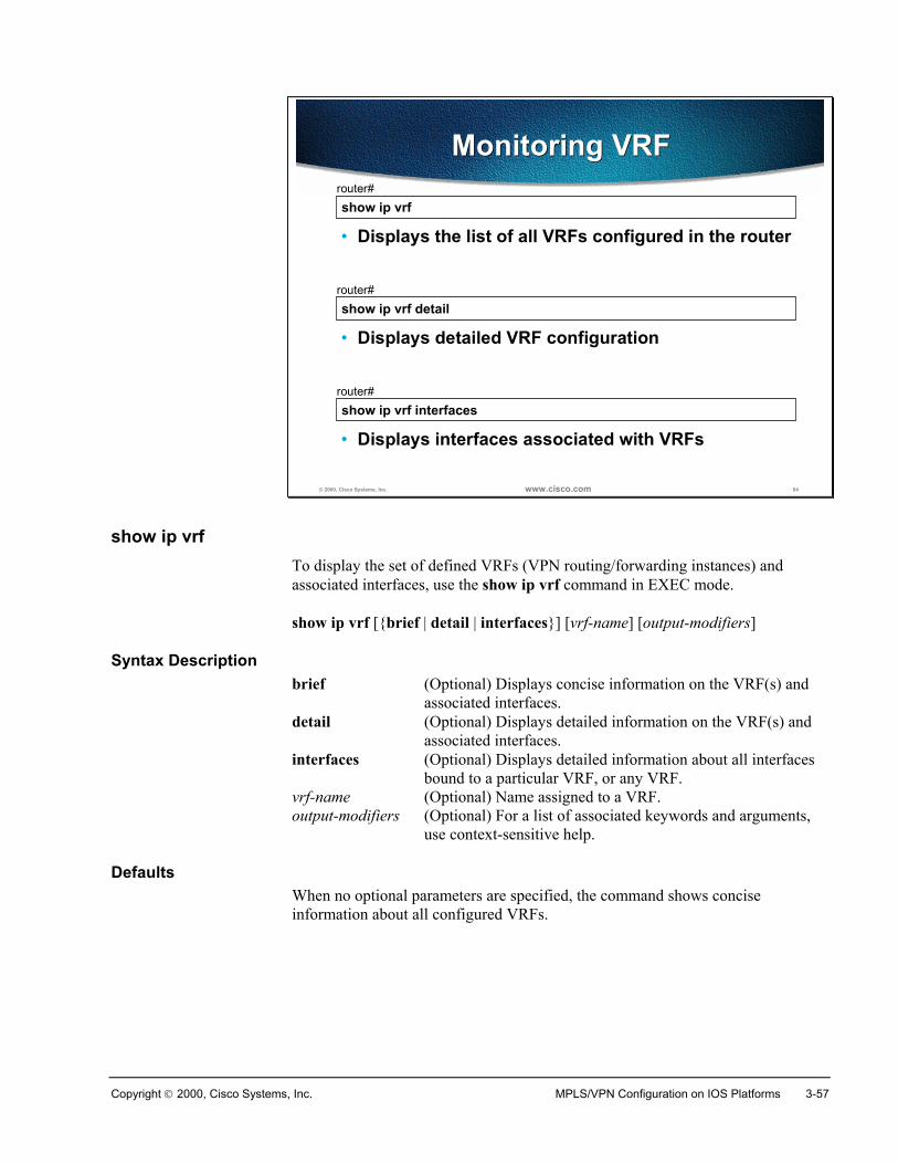
Copyright 2000, Cisco Systems, Inc. MPLS/VPN Configuration on IOS Platforms 3-57
© 2000, Cisco Systems, Inc. www.cisco.com 64
show ip vrfrouter#
• Displays the list of all VRFs configured in the router
Monitoring VRFMonitoring VRF
show ip vrf detailrouter#
• Displays detailed VRF configuration
show ip vrf interfacesrouter#
• Displays interfaces associated with VRFs
show ip vrfTo display the set of defined VRFs (VPN routing/forwarding instances) andassociated interfaces, use the show ip vrf command in EXEC mode.
show ip vrf [{brief | detail | interfaces}] [vrf-name] [output-modifiers]
Syntax Descriptionbrief (Optional) Displays concise information on the VRF(s) and
associated interfaces.detail (Optional) Displays detailed information on the VRF(s) and
associated interfaces.interfaces (Optional) Displays detailed information about all interfaces
bound to a particular VRF, or any VRF. vrf-name (Optional) Name assigned to a VRF.output-modifiers (Optional) For a list of associated keywords and arguments,
use context-sensitive help.
DefaultsWhen no optional parameters are specified, the command shows conciseinformation about all configured VRFs.
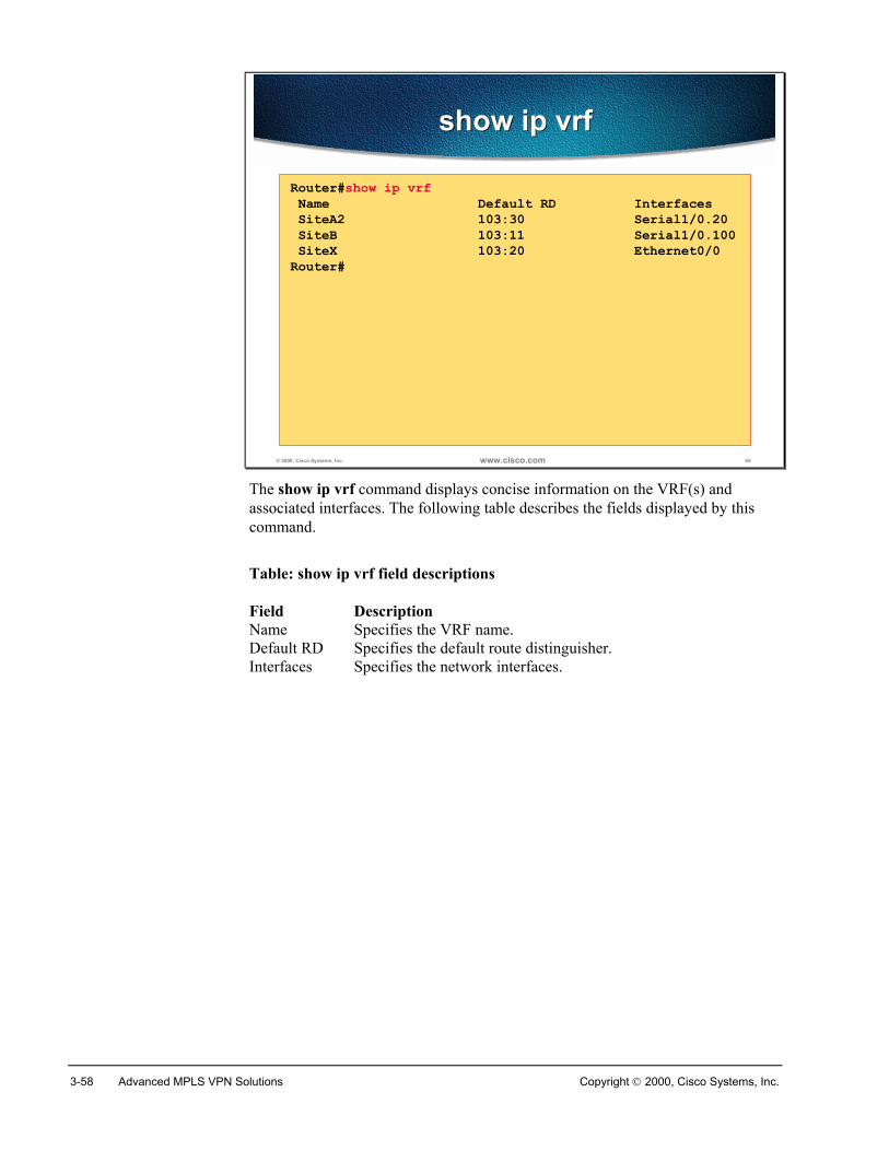
3-58 Advanced MPLS VPN Solutions Copyright 2000, Cisco Systems, Inc.
© 2000, Cisco Systems, Inc. www.cisco.com 65
show ip vrfshow ip vrf
Router#show ip vrf Name Default RD Interfaces SiteA2 103:30 Serial1/0.20 SiteB 103:11 Serial1/0.100 SiteX 103:20 Ethernet0/0Router#
The show ip vrf command displays concise information on the VRF(s) andassociated interfaces. The following table describes the fields displayed by thiscommand.
Table: show ip vrf field descriptions
Field Description Name Specifies the VRF name. Default RD Specifies the default route distinguisher. Interfaces Specifies the network interfaces.
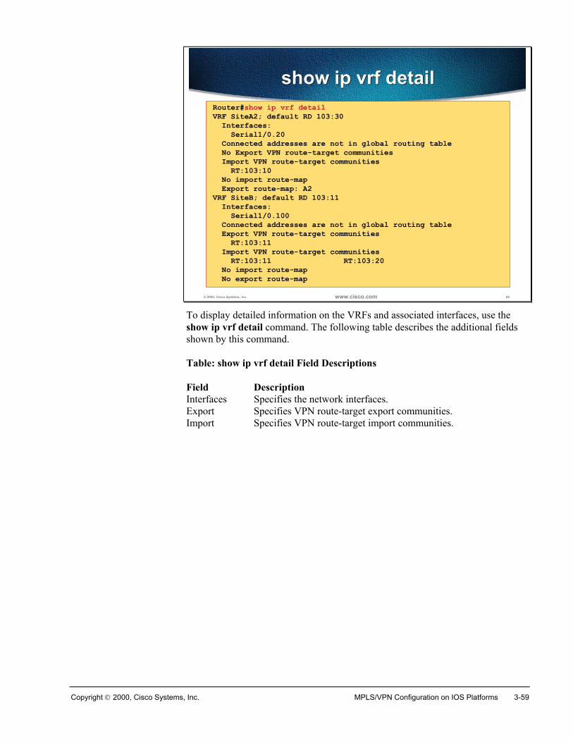
Copyright 2000, Cisco Systems, Inc. MPLS/VPN Configuration on IOS Platforms 3-59
© 2000, Cisco Systems, Inc. www.cisco.com 66
show ip vrf detailshow ip vrf detailRouter#show ip vrf detailVRF SiteA2; default RD 103:30 Interfaces: Serial1/0.20 Connected addresses are not in global routing table No Export VPN route-target communities Import VPN route-target communities RT:103:10 No import route-map Export route-map: A2VRF SiteB; default RD 103:11 Interfaces: Serial1/0.100 Connected addresses are not in global routing table Export VPN route-target communities RT:103:11 Import VPN route-target communities RT:103:11 RT:103:20 No import route-map No export route-map
To display detailed information on the VRFs and associated interfaces, use theshow ip vrf detail command. The following table describes the additional fieldsshown by this command.
Table: show ip vrf detail Field Descriptions
Field Description Interfaces Specifies the network interfaces. Export Specifies VPN route-target export communities. Import Specifies VPN route-target import communities.
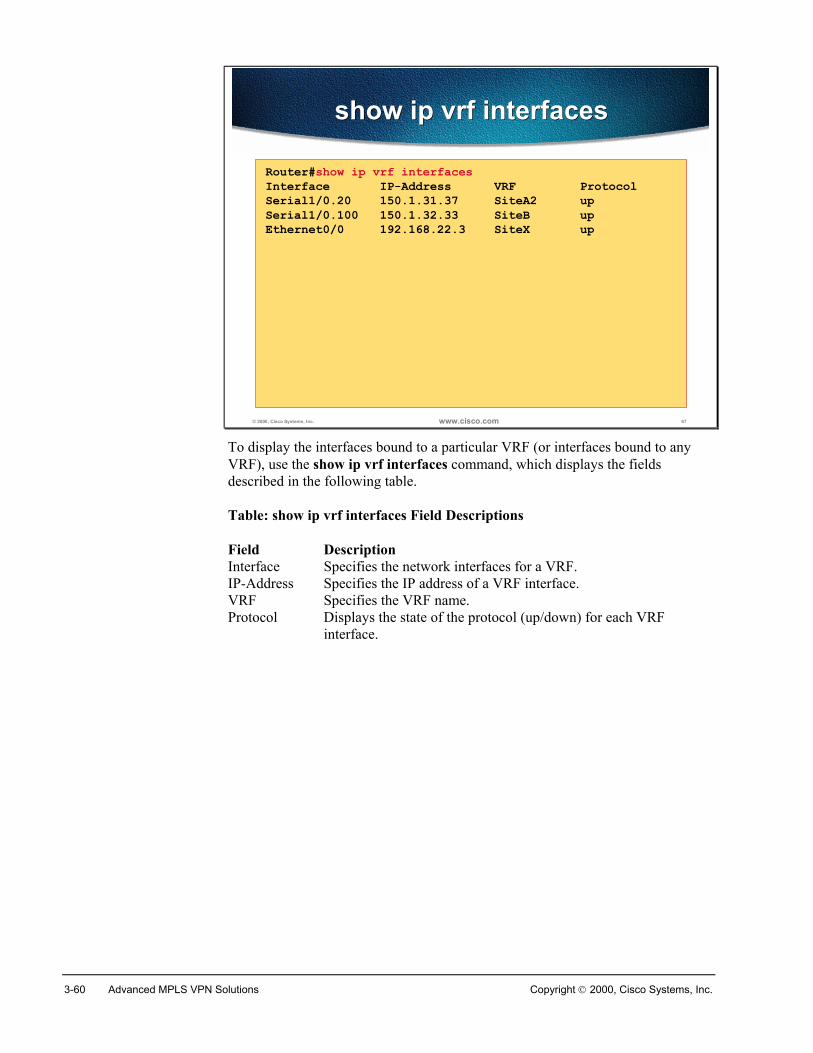
3-60 Advanced MPLS VPN Solutions Copyright 2000, Cisco Systems, Inc.
© 2000, Cisco Systems, Inc. www.cisco.com 67
show ip vrf interfacesshow ip vrf interfaces
Router#show ip vrf interfacesInterface IP-Address VRF ProtocolSerial1/0.20 150.1.31.37 SiteA2 upSerial1/0.100 150.1.32.33 SiteB upEthernet0/0 192.168.22.3 SiteX up
To display the interfaces bound to a particular VRF (or interfaces bound to anyVRF), use the show ip vrf interfaces command, which displays the fieldsdescribed in the following table.
Table: show ip vrf interfaces Field Descriptions
Field Description Interface Specifies the network interfaces for a VRF.IP-Address Specifies the IP address of a VRF interface.VRF Specifies the VRF name.Protocol Displays the state of the protocol (up/down) for each VRF
interface.
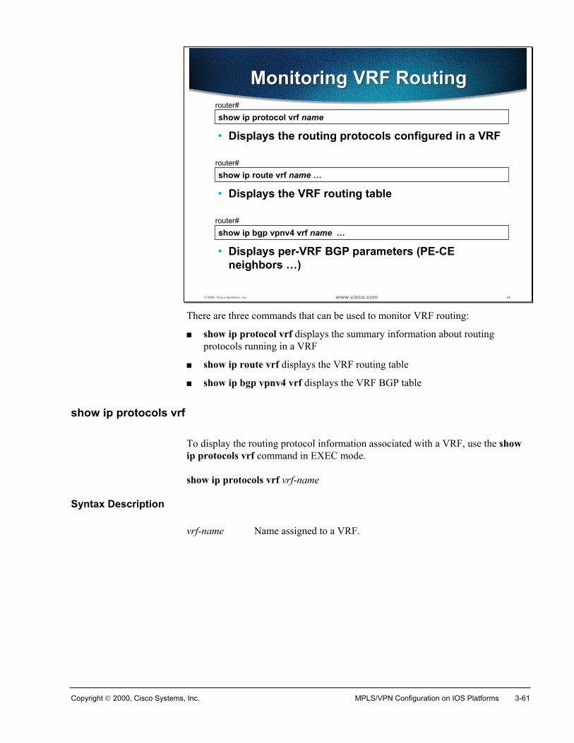
Copyright 2000, Cisco Systems, Inc. MPLS/VPN Configuration on IOS Platforms 3-61
© 2000, Cisco Systems, Inc. www.cisco.com 68
show ip protocol vrf namerouter#
• Displays the routing protocols configured in a VRF
Monitoring VRF RoutingMonitoring VRF Routing
show ip route vrf name …router#
• Displays the VRF routing table
show ip bgp vpnv4 vrf name …router#
• Displays per-VRF BGP parameters (PE-CEneighbors …)
There are three commands that can be used to monitor VRF routing:
� show ip protocol vrf displays the summary information about routingprotocols running in a VRF
� show ip route vrf displays the VRF routing table
� show ip bgp vpnv4 vrf displays the VRF BGP table
show ip protocols vrf
To display the routing protocol information associated with a VRF, use the showip protocols vrf command in EXEC mode.
show ip protocols vrf vrf-name
Syntax Description
vrf-name Name assigned to a VRF.
3-62 Advanced MPLS VPN Solutions Copyright 2000, Cisco Systems, Inc.
show ip route vrf
To display the IP routing table associated with a VRF (VPN routing/forwardinginstance), use the show ip route vrf command in EXEC mode.
show ip route vrf vrf-name [connected] [protocol [as-number] [tag] [output-modifiers]] [list number [output-modifiers]] [profile] [static [output-modifiers]][summary [output-modifiers]] [supernets-only [output-modifiers]] [traffic-engineering [output-modifiers]]
Syntax Description
vrf-name Name assigned to the VRF.connected (Optional) Displays all connected routes in a VRF.protocol (Optional) To specify a routing protocol, use one of the
following keywords: bgp, egp, eigrp, hello, igrp, isis,ospf, or rip.
as-number (Optional) Autonomous system number.tag (Optional) IOS routing area label.output-modifiers (Optional) For a list of associated keywords and
arguments, use context-sensitive help.list number (Optional) Specifies the IP access list to display. profile (Optional) Displays the IP routing table profile.static (Optional) Displays static routes. summary (Optional) Displays a summary of routes.supernets-only (Optional) Displays supernet entries only. traffic-engineering (Optional) Displays only traffic-engineered routes.
show ip bgp vpnv4
To display VPN address information from the BGP table, use the show ip bgpvpnv4 command in EXEC mode.
show ip bgp vpnv4 {all | rd route-distinguisher | vrf vrf-name} [ip-prefix/length[longer-prefixes] [output-modifiers]] [network-address [mask] [longer-prefixes][output-modifiers]] [cidr-only] [community] [community-list] [dampened-paths][filter-list] [flap-statistics] [inconsistent-as][neighbors] [paths [line]] [peer-group][quote-regexp] [regexp] [summary] [tags]
Syntax Description
all Displays the complete VPNv4 database.rd route-distinguisher Displays NLRIs that have a matching route distinguisher.vrf vrf-name Displays NLRIs associated with the named VRF.ip-prefix/length (Optional) IP prefix address (in dotted decimal format)
and length of mask (0 to 32). longer-prefixes (Optional) Displays the entry, if any, that exactly matches
the specified prefix parameter, as well as all entries thatmatch the prefix in a "longest-match" sense. That is,prefixes for which the specified prefix is an initialsubstring.
Copyright 2000, Cisco Systems, Inc. MPLS/VPN Configuration on IOS Platforms 3-63
output-modifiers (Optional) For a list of associated keywords andarguments, use context-sensitive help.
network-address (Optional) IP address of a network in the BGP routingtable.
mask (Optional) Mask of the network address, in dotteddecimal format.
cidr-only (Optional) Displays only routes that have non-natural netmasks.
community (Optional) Displays routes matching this community.community-list (Optional) Displays routes matching this community list.dampened-paths (Optional) Displays paths suppressed on account of
dampening (BGP route from peer is up and down).filter-list (Optional) Displays routes conforming to the filter list.flap-statistics (Optional) Displays flap statistics of routes.inconsistent-as (Optional) Displays only routes that have inconsistent
autonomous systems of origin.neighbors (Optional) Displays details about TCP and BGP neighbor
connections. paths (Optional) Displays path information.line (Optional) A regular expression to match the BGP AS
paths.peer-group (Optional) Displays information about peer groups.quote-regexp (Optional) Displays routes matching the AS path "regular
expression." regexp (Optional) Displays routes matching the AS path “regular
expression.” summary (Optional) Displays BGP neighbor status.tags (Optional) Displays incoming and outgoing BGP labels
for each NLRI.
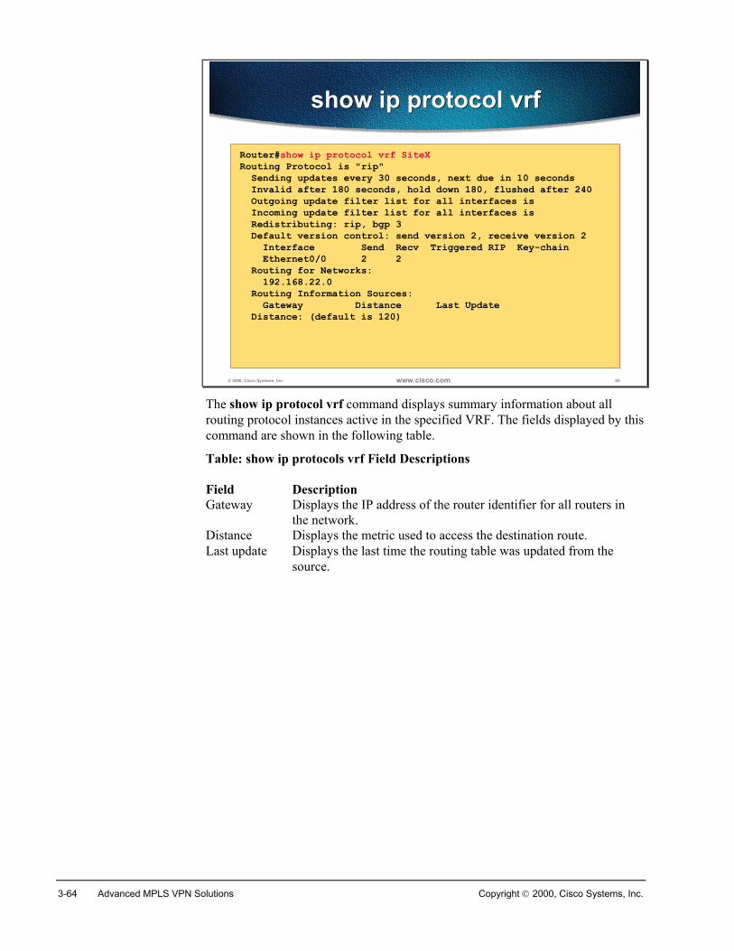
3-64 Advanced MPLS VPN Solutions Copyright 2000, Cisco Systems, Inc.
© 2000, Cisco Systems, Inc. www.cisco.com 69
show ip protocol vrfshow ip protocol vrf
Router#show ip protocol vrf SiteXRouting Protocol is "rip" Sending updates every 30 seconds, next due in 10 seconds Invalid after 180 seconds, hold down 180, flushed after 240 Outgoing update filter list for all interfaces is Incoming update filter list for all interfaces is Redistributing: rip, bgp 3 Default version control: send version 2, receive version 2 Interface Send Recv Triggered RIP Key-chain Ethernet0/0 2 2 Routing for Networks: 192.168.22.0 Routing Information Sources: Gateway Distance Last Update Distance: (default is 120)
The show ip protocol vrf command displays summary information about allrouting protocol instances active in the specified VRF. The fields displayed by thiscommand are shown in the following table.
Table: show ip protocols vrf Field Descriptions
Field Description Gateway Displays the IP address of the router identifier for all routers in
the network. Distance Displays the metric used to access the destination route. Last update Displays the last time the routing table was updated from the
source.
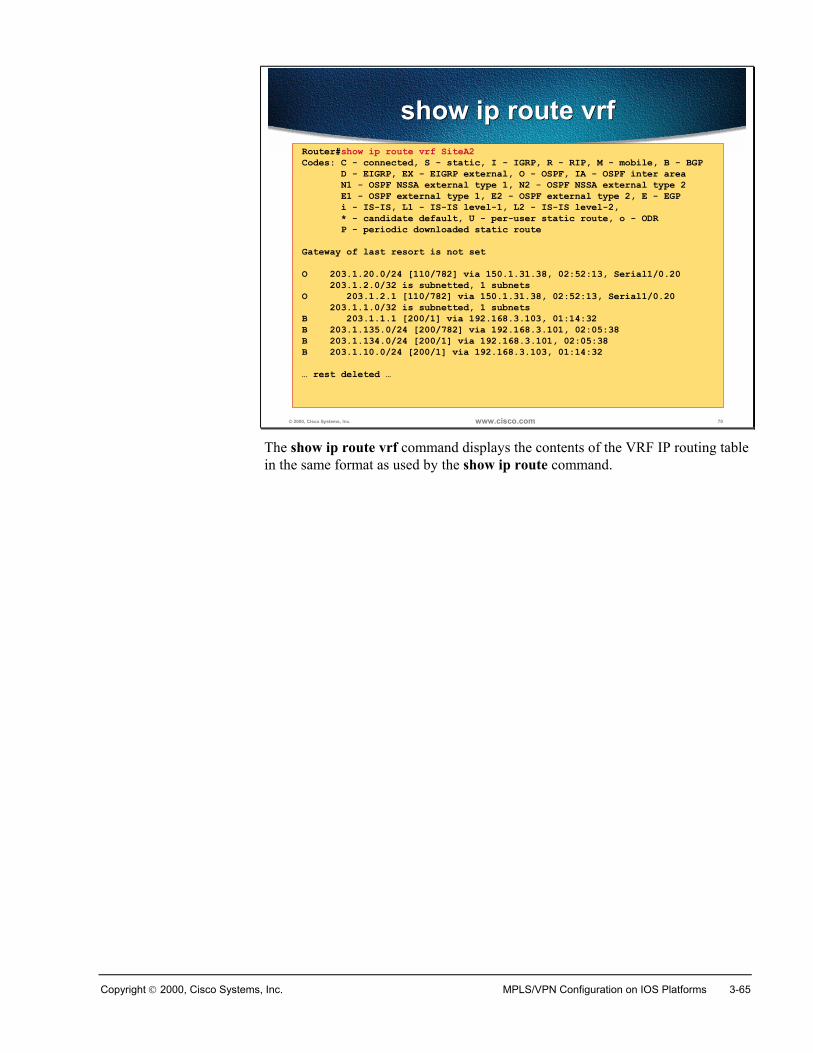
Copyright 2000, Cisco Systems, Inc. MPLS/VPN Configuration on IOS Platforms 3-65
© 2000, Cisco Systems, Inc. www.cisco.com 70
show ip route vrfshow ip route vrfRouter#show ip route vrf SiteA2Codes: C - connected, S - static, I - IGRP, R - RIP, M - mobile, B - BGP D - EIGRP, EX - EIGRP external, O - OSPF, IA - OSPF inter area N1 - OSPF NSSA external type 1, N2 - OSPF NSSA external type 2 E1 - OSPF external type 1, E2 - OSPF external type 2, E - EGP i - IS-IS, L1 - IS-IS level-1, L2 - IS-IS level-2, * - candidate default, U - per-user static route, o - ODR P - periodic downloaded static routeGateway of last resort is not setO 203.1.20.0/24 [110/782] via 150.1.31.38, 02:52:13, Serial1/0.20 203.1.2.0/32 is subnetted, 1 subnetsO 203.1.2.1 [110/782] via 150.1.31.38, 02:52:13, Serial1/0.20 203.1.1.0/32 is subnetted, 1 subnetsB 203.1.1.1 [200/1] via 192.168.3.103, 01:14:32B 203.1.135.0/24 [200/782] via 192.168.3.101, 02:05:38B 203.1.134.0/24 [200/1] via 192.168.3.101, 02:05:38B 203.1.10.0/24 [200/1] via 192.168.3.103, 01:14:32… rest deleted …
The show ip route vrf command displays the contents of the VRF IP routing tablein the same format as used by the show ip route command.
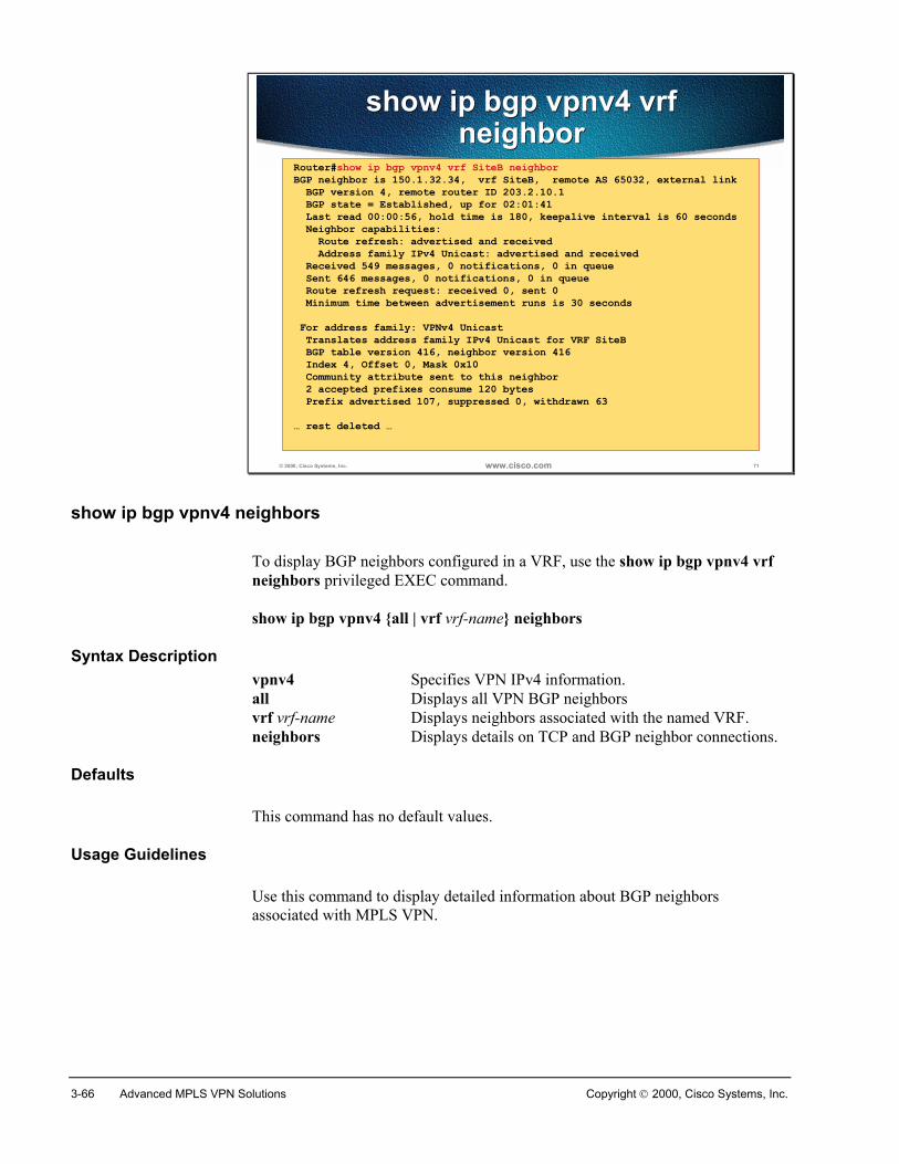
3-66 Advanced MPLS VPN Solutions Copyright 2000, Cisco Systems, Inc.
© 2000, Cisco Systems, Inc. www.cisco.com 71
show ip bgp vpnv4 vrfneighbor
show ip bgp vpnv4 vrfneighbor
Router#show ip bgp vpnv4 vrf SiteB neighborBGP neighbor is 150.1.32.34, vrf SiteB, remote AS 65032, external link BGP version 4, remote router ID 203.2.10.1 BGP state = Established, up for 02:01:41 Last read 00:00:56, hold time is 180, keepalive interval is 60 seconds Neighbor capabilities: Route refresh: advertised and received Address family IPv4 Unicast: advertised and received Received 549 messages, 0 notifications, 0 in queue Sent 646 messages, 0 notifications, 0 in queue Route refresh request: received 0, sent 0 Minimum time between advertisement runs is 30 seconds For address family: VPNv4 Unicast Translates address family IPv4 Unicast for VRF SiteB BGP table version 416, neighbor version 416 Index 4, Offset 0, Mask 0x10 Community attribute sent to this neighbor 2 accepted prefixes consume 120 bytes Prefix advertised 107, suppressed 0, withdrawn 63… rest deleted …
show ip bgp vpnv4 neighbors
To display BGP neighbors configured in a VRF, use the show ip bgp vpnv4 vrfneighbors privileged EXEC command.
show ip bgp vpnv4 {all | vrf vrf-name} neighbors
Syntax Descriptionvpnv4 Specifies VPN IPv4 information.all Displays all VPN BGP neighborsvrf vrf-name Displays neighbors associated with the named VRF.neighbors Displays details on TCP and BGP neighbor connections.
Defaults
This command has no default values.
Usage Guidelines
Use this command to display detailed information about BGP neighborsassociated with MPLS VPN.
Copyright 2000, Cisco Systems, Inc. MPLS/VPN Configuration on IOS Platforms 3-67
© 2000, Cisco Systems, Inc. www.cisco.com 72
show ip bgp neighborrouter#
• Displays global BGP neighbors and the protocolsnegotiated with these neighbors
Monitoring MP-BGP SessionsMonitoring MP-BGP Sessions
The show ip bgp neighbor command, described in details in the Basic BGPTechnology and Configuration lesson is also used to monitor BGP sessions withother PE routers as well as the address families negotiated with these neighbors.
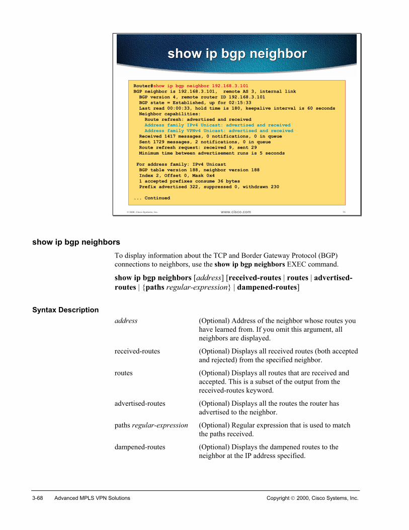
3-68 Advanced MPLS VPN Solutions Copyright 2000, Cisco Systems, Inc.
© 2000, Cisco Systems, Inc. www.cisco.com 73
show ip bgp neighborshow ip bgp neighbor
Router#show ip bgp neighbor 192.168.3.101BGP neighbor is 192.168.3.101, remote AS 3, internal link BGP version 4, remote router ID 192.168.3.101 BGP state = Established, up for 02:15:33 Last read 00:00:33, hold time is 180, keepalive interval is 60 seconds Neighbor capabilities: Route refresh: advertised and received Address family IPv4 Unicast: advertised and received Address family VPNv4 Unicast: advertised and received Received 1417 messages, 0 notifications, 0 in queue Sent 1729 messages, 2 notifications, 0 in queue Route refresh request: received 9, sent 29 Minimum time between advertisement runs is 5 seconds For address family: IPv4 Unicast BGP table version 188, neighbor version 188 Index 2, Offset 0, Mask 0x4 1 accepted prefixes consume 36 bytes Prefix advertised 322, suppressed 0, withdrawn 230... Continued
show ip bgp neighborsTo display information about the TCP and Border Gateway Protocol (BGP)connections to neighbors, use the show ip bgp neighbors EXEC command.
show ip bgp neighbors [address] [received-routes | routes | advertised-routes | {paths regular-expression} | dampened-routes]
Syntax Descriptionaddress (Optional) Address of the neighbor whose routes you
have learned from. If you omit this argument, allneighbors are displayed.
received-routes (Optional) Displays all received routes (both acceptedand rejected) from the specified neighbor.
routes (Optional) Displays all routes that are received andaccepted. This is a subset of the output from thereceived-routes keyword.
advertised-routes (Optional) Displays all the routes the router hasadvertised to the neighbor.
paths regular-expression (Optional) Regular expression that is used to matchthe paths received.
dampened-routes (Optional) Displays the dampened routes to theneighbor at the IP address specified.
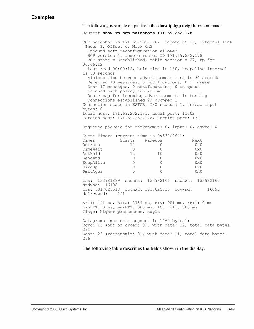
Copyright 2000, Cisco Systems, Inc. MPLS/VPN Configuration on IOS Platforms 3-69
ExamplesThe following is sample output from the show ip bgp neighbors command:Router# show ip bgp neighbors 171.69.232.178BGP neighbor is 171.69.232.178, remote AS 10, external link Index 1, Offset 0, Mask 0x2 Inbound soft reconfiguration allowed BGP version 4, remote router ID 171.69.232.178 BGP state = Established, table version = 27, up for00:06:12 Last read 00:00:12, hold time is 180, keepalive intervalis 60 seconds Minimum time between advertisement runs is 30 seconds Received 19 messages, 0 notifications, 0 in queue Sent 17 messages, 0 notifications, 0 in queue Inbound path policy configured Route map for incoming advertisements is testing Connections established 2; dropped 1Connection state is ESTAB, I/O status: 1, unread inputbytes: 0Local host: 171.69.232.181, Local port: 11002Foreign host: 171.69.232.178, Foreign port: 179
Enqueued packets for retransmit: 0, input: 0, saved: 0
Event Timers (current time is 0x530C294):Timer Starts Wakeups NextRetrans 12 0 0x0TimeWait 0 0 0x0AckHold 12 10 0x0SendWnd 0 0 0x0KeepAlive 0 0 0x0GiveUp 0 0 0x0PmtuAger 0 0 0x0
iss: 133981889 snduna: 133982166 sndnxt: 133982166sndwnd: 16108irs: 3317025518 rcvnxt: 3317025810 rcvwnd: 16093delrcvwnd: 291
SRTT: 441 ms, RTTO: 2784 ms, RTV: 951 ms, KRTT: 0 msminRTT: 0 ms, maxRTT: 300 ms, ACK hold: 300 msFlags: higher precedence, nagle
Datagrams (max data segment is 1460 bytes):Rcvd: 15 (out of order: 0), with data: 12, total data bytes:291Sent: 23 (retransmit: 0), with data: 11, total data bytes:276
The following table describes the fields shown in the display.
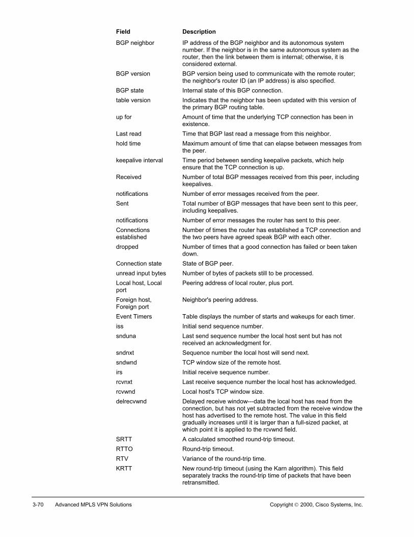
3-70 Advanced MPLS VPN Solutions Copyright 2000, Cisco Systems, Inc.
Field Description
BGP neighbor IP address of the BGP neighbor and its autonomous systemnumber. If the neighbor is in the same autonomous system as therouter, then the link between them is internal; otherwise, it isconsidered external.
BGP version BGP version being used to communicate with the remote router;the neighbor's router ID (an IP address) is also specified.
BGP state Internal state of this BGP connection.table version Indicates that the neighbor has been updated with this version of
the primary BGP routing table.up for Amount of time that the underlying TCP connection has been in
existence.Last read Time that BGP last read a message from this neighbor.hold time Maximum amount of time that can elapse between messages from
the peer.keepalive interval Time period between sending keepalive packets, which help
ensure that the TCP connection is up.Received Number of total BGP messages received from this peer, including
keepalives.notifications Number of error messages received from the peer.Sent Total number of BGP messages that have been sent to this peer,
including keepalives.notifications Number of error messages the router has sent to this peer.Connectionsestablished
Number of times the router has established a TCP connection andthe two peers have agreed speak BGP with each other.
dropped Number of times that a good connection has failed or been takendown.
Connection state State of BGP peer.unread input bytes Number of bytes of packets still to be processed.Local host, Localport
Peering address of local router, plus port.
Foreign host,Foreign port
Neighbor's peering address.
Event Timers Table displays the number of starts and wakeups for each timer.iss Initial send sequence number.snduna Last send sequence number the local host sent but has not
received an acknowledgment for.sndnxt Sequence number the local host will send next.sndwnd TCP window size of the remote host.irs Initial receive sequence number.rcvnxt Last receive sequence number the local host has acknowledged.rcvwnd Local host's TCP window size.delrecvwnd Delayed receive window---data the local host has read from the
connection, but has not yet subtracted from the receive window thehost has advertised to the remote host. The value in this fieldgradually increases until it is larger than a full-sized packet, atwhich point it is applied to the rcvwnd field.
SRTT A calculated smoothed round-trip timeout.RTTO Round-trip timeout.RTV Variance of the round-trip time.KRTT New round-trip timeout (using the Karn algorithm). This field
separately tracks the round-trip time of packets that have beenretransmitted.
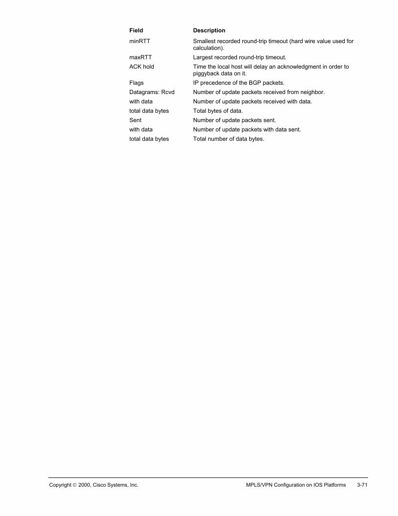
Copyright 2000, Cisco Systems, Inc. MPLS/VPN Configuration on IOS Platforms 3-71
Field Description
minRTT Smallest recorded round-trip timeout (hard wire value used forcalculation).
maxRTT Largest recorded round-trip timeout.ACK hold Time the local host will delay an acknowledgment in order to
piggyback data on it.Flags IP precedence of the BGP packets.Datagrams: Rcvd Number of update packets received from neighbor.with data Number of update packets received with data.total data bytes Total bytes of data.Sent Number of update packets sent.with data Number of update packets with data sent.total data bytes Total number of data bytes.
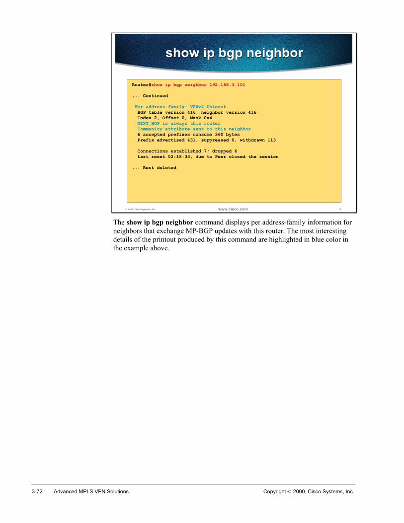
3-72 Advanced MPLS VPN Solutions Copyright 2000, Cisco Systems, Inc.
© 2000, Cisco Systems, Inc. www.cisco.com 74
show ip bgp neighborshow ip bgp neighbor
Router#show ip bgp neighbor 192.168.3.101... Continued For address family: VPNv4 Unicast BGP table version 416, neighbor version 416 Index 2, Offset 0, Mask 0x4 NEXT_HOP is always this router Community attribute sent to this neighbor 6 accepted prefixes consume 360 bytes Prefix advertised 431, suppressed 0, withdrawn 113 Connections established 7; dropped 6 Last reset 02:18:33, due to Peer closed the session... Rest deleted
The show ip bgp neighbor command displays per address-family information forneighbors that exchange MP-BGP updates with this router. The most interestingdetails of the printout produced by this command are highlighted in blue color inthe example above.
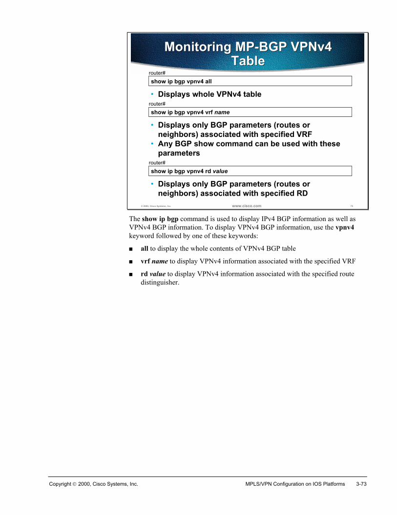
Copyright 2000, Cisco Systems, Inc. MPLS/VPN Configuration on IOS Platforms 3-73
© 2000, Cisco Systems, Inc. www.cisco.com 75
show ip bgp vpnv4 allrouter#
• Displays whole VPNv4 table
Monitoring MP-BGP VPNv4Table
Monitoring MP-BGP VPNv4Table
show ip bgp vpnv4 vrf namerouter#
• Displays only BGP parameters (routes orneighbors) associated with specified VRF
• Any BGP show command can be used with theseparameters
show ip bgp vpnv4 rd valuerouter#
• Displays only BGP parameters (routes orneighbors) associated with specified RD
The show ip bgp command is used to display IPv4 BGP information as well asVPNv4 BGP information. To display VPNv4 BGP information, use the vpnv4keyword followed by one of these keywords:
� all to display the whole contents of VPNv4 BGP table
� vrf name to display VPNv4 information associated with the specified VRF
� rd value to display VPNv4 information associated with the specified routedistinguisher.
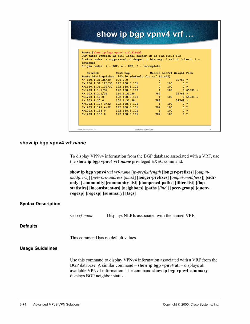
3-74 Advanced MPLS VPN Solutions Copyright 2000, Cisco Systems, Inc.
© 2000, Cisco Systems, Inc. www.cisco.com 76
show ip bgp vpnv4 vrf …show ip bgp vpnv4 vrf …
Router#show ip bgp vpnv4 vrf SiteA2BGP table version is 416, local router ID is 192.168.3.102Status codes: s suppressed, d damped, h history, * valid, > best, i -internalOrigin codes: i - IGP, e - EGP, ? - incomplete Network Next Hop Metric LocPrf Weight PathRoute Distinguisher: 103:30 (default for vrf SiteA2)*> 150.1.31.36/30 0.0.0.0 0 32768 ?*>i150.1.31.128/30 192.168.3.101 0 100 0 ?*>i150.1.31.132/30 192.168.3.101 0 100 0 ?*>i203.1.1.1/32 192.168.3.103 1 100 0 65031 i*> 203.1.2.1/32 150.1.31.38 782 32768 ?*>i203.1.10.0 192.168.3.103 1 100 0 65031 i*> 203.1.20.0 150.1.31.38 782 32768 ?*>i203.1.127.3/32 192.168.3.101 1 100 0 ?*>i203.1.127.4/32 192.168.3.101 782 100 0 ?*>i203.1.134.0 192.168.3.101 1 100 0 ?*>i203.1.135.0 192.168.3.101 782 100 0 ?
show ip bgp vpnv4 vrf name
To display VPNv4 information from the BGP database associated with a VRF, usethe show ip bgp vpnv4 vrf name privileged EXEC command.
show ip bgp vpnv4 vrf vrf-name [ip-prefix/length [longer-prefixes] [output-modifiers]] [network-address [mask] [longer-prefixes] [output-modifiers]] [cidr-only] [community][community-list] [dampened-paths] [filter-list] [flap-statistics] [inconsistent-as] [neighbors] [paths [line]] [peer-group] [quote-regexp] [regexp] [summary] [tags]
Syntax Description
vrf vrf-name Displays NLRIs associated with the named VRF.
Defaults
This command has no default values.
Usage Guidelines
Use this command to display VPNv4 information associated with a VRF from theBGP database. A similar command – show ip bgp vpnv4 all – displays allavailable VPNv4 information. The command show ip bgp vpnv4 summarydisplays BGP neighbor status.
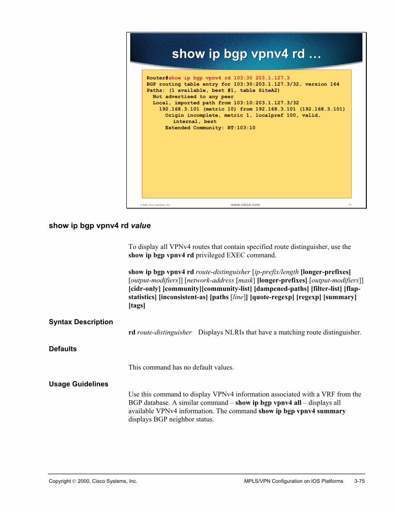
Copyright 2000, Cisco Systems, Inc. MPLS/VPN Configuration on IOS Platforms 3-75
© 2000, Cisco Systems, Inc. www.cisco.com 77
show ip bgp vpnv4 rd …show ip bgp vpnv4 rd …Router#show ip bgp vpnv4 rd 103:30 203.1.127.3BGP routing table entry for 103:30:203.1.127.3/32, version 164Paths: (1 available, best #1, table SiteA2) Not advertised to any peer Local, imported path from 103:10:203.1.127.3/32 192.168.3.101 (metric 10) from 192.168.3.101 (192.168.3.101) Origin incomplete, metric 1, localpref 100, valid,
internal, best Extended Community: RT:103:10
show ip bgp vpnv4 rd value
To display all VPNv4 routes that contain specified route distinguisher, use theshow ip bgp vpnv4 rd privileged EXEC command.
show ip bgp vpnv4 rd route-distinguisher [ip-prefix/length [longer-prefixes][output-modifiers]] [network-address [mask] [longer-prefixes] [output-modifiers]][cidr-only] [community][community-list] [dampened-paths] [filter-list] [flap-statistics] [inconsistent-as] [paths [line]] [quote-regexp] [regexp] [summary][tags]
Syntax Descriptionrd route-distinguisher Displays NLRIs that have a matching route distinguisher.
Defaults
This command has no default values.
Usage GuidelinesUse this command to display VPNv4 information associated with a VRF from theBGP database. A similar command – show ip bgp vpnv4 all – displays allavailable VPNv4 information. The command show ip bgp vpnv4 summarydisplays BGP neighbor status.
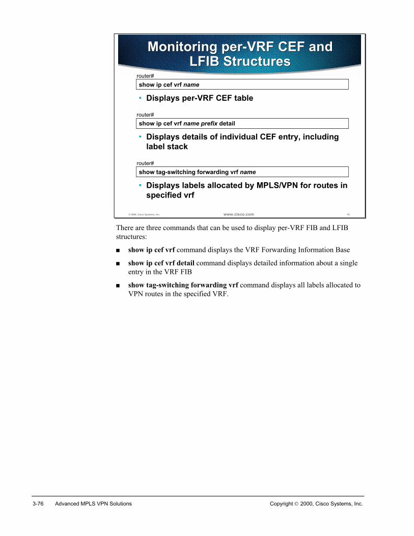
3-76 Advanced MPLS VPN Solutions Copyright 2000, Cisco Systems, Inc.
© 2000, Cisco Systems, Inc. www.cisco.com 78
show ip cef vrf namerouter#
• Displays per-VRF CEF table
Monitoring per-VRF CEF andLFIB Structures
Monitoring per-VRF CEF andLFIB Structures
show ip cef vrf name prefix detailrouter#
• Displays details of individual CEF entry, includinglabel stack
show tag-switching forwarding vrf namerouter#
• Displays labels allocated by MPLS/VPN for routes inspecified vrf
There are three commands that can be used to display per-VRF FIB and LFIBstructures:
� show ip cef vrf command displays the VRF Forwarding Information Base
� show ip cef vrf detail command displays detailed information about a singleentry in the VRF FIB
� show tag-switching forwarding vrf command displays all labels allocated toVPN routes in the specified VRF.
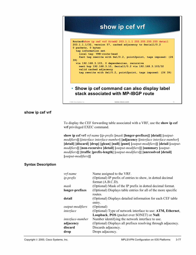
Copyright 2000, Cisco Systems, Inc. MPLS/VPN Configuration on IOS Platforms 3-77
© 2000, Cisco Systems, Inc. www.cisco.com 79
show ip cef vrfshow ip cef vrf
Router#show ip cef vrf SiteA2 203.1.1.1 255.255.255.255 detail203.1.1.1/32, version 57, cached adjacency to Serial1/0.20 packets, 0 bytes tag information set local tag: VPN-route-head fast tag rewrite with Se1/0.2, point2point, tags imposed: {2639} via 192.168.3.103, 0 dependencies, recursive next hop 192.168.3.10, Serial1/0.2 via 192.168.3.103/32 valid cached adjacency tag rewrite with Se1/0.2, point2point, tags imposed: {26 39}
• Show ip cef command can also display labelstack associated with MP-IBGP route
show ip cef vrf
To display the CEF forwarding table associated with a VRF, use the show ip cefvrf privileged EXEC command.
show ip cef vrf vrf-name [ip-prefix [mask [longer-prefixes]] [detail] [output-modifiers]] [interface interface-number] [adjacency [interface interface-number][detail] [discard] [drop] [glean] [null] [punt] [output-modifiers]] [detail [output-modifiers]] [non-recursive [detail] [output-modifiers]] [summary [output-modifiers]] [traffic [prefix-length] [output-modifiers]] [unresolved [detail][output-modifiers]]
Syntax Description
vrf-name Name assigned to the VRF.ip-prefix (Optional) IP prefix of entries to show, in dotted decimal
format (A.B.C.D).mask (Optional) Mask of the IP prefix in dotted decimal format.longer-prefixes (Optional) Displays table entries for all of the more specific
routes. detail (Optional) Displays detailed information for each CEF table
entry. output-modifiers (Optional) interface (Optional) Type of network interface to use: ATM, Ethernet,
Loopback, POS (packet over SONET) or Null.interface-number Number identifying the network interface to use.adjacency (Optional) Displays all prefixes resolving through adjacency.discard Discards adjacency.drop Drops adjacency.
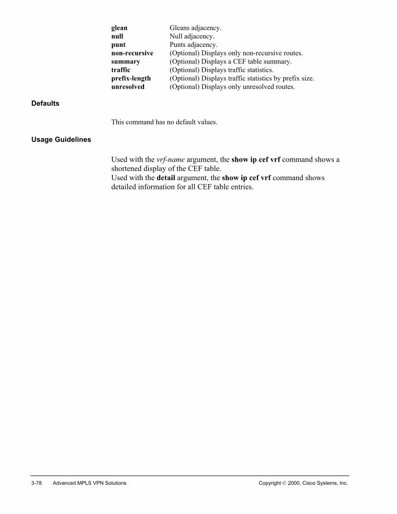
3-78 Advanced MPLS VPN Solutions Copyright 2000, Cisco Systems, Inc.
glean Gleans adjacency.null Null adjacency.punt Punts adjacency.non-recursive (Optional) Displays only non-recursive routes.summary (Optional) Displays a CEF table summary.traffic (Optional) Displays traffic statistics.prefix-length (Optional) Displays traffic statistics by prefix size.unresolved (Optional) Displays only unresolved routes.
Defaults
This command has no default values.
Usage Guidelines
Used with the vrf-name argument, the show ip cef vrf command shows ashortened display of the CEF table.Used with the detail argument, the show ip cef vrf command showsdetailed information for all CEF table entries.
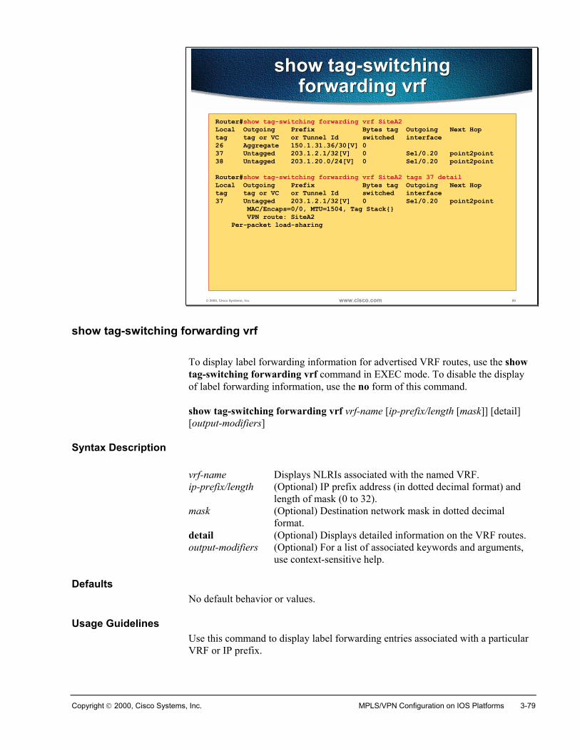
Copyright 2000, Cisco Systems, Inc. MPLS/VPN Configuration on IOS Platforms 3-79
© 2000, Cisco Systems, Inc. www.cisco.com 80
show tag-switchingforwarding vrf
show tag-switchingforwarding vrf
Router#show tag-switching forwarding vrf SiteA2Local Outgoing Prefix Bytes tag Outgoing Next Hoptag tag or VC or Tunnel Id switched interface26 Aggregate 150.1.31.36/30[V] 037 Untagged 203.1.2.1/32[V] 0 Se1/0.20 point2point38 Untagged 203.1.20.0/24[V] 0 Se1/0.20 point2pointRouter#show tag-switching forwarding vrf SiteA2 tags 37 detailLocal Outgoing Prefix Bytes tag Outgoing Next Hoptag tag or VC or Tunnel Id switched interface37 Untagged 203.1.2.1/32[V] 0 Se1/0.20 point2point MAC/Encaps=0/0, MTU=1504, Tag Stack{} VPN route: SiteA2 Per-packet load-sharing
show tag-switching forwarding vrf
To display label forwarding information for advertised VRF routes, use the showtag-switching forwarding vrf command in EXEC mode. To disable the displayof label forwarding information, use the no form of this command.
show tag-switching forwarding vrf vrf-name [ip-prefix/length [mask]] [detail][output-modifiers]
Syntax Description
vrf-name Displays NLRIs associated with the named VRF.ip-prefix/length (Optional) IP prefix address (in dotted decimal format) and
length of mask (0 to 32). mask (Optional) Destination network mask in dotted decimal
format.detail (Optional) Displays detailed information on the VRF routes.output-modifiers (Optional) For a list of associated keywords and arguments,
use context-sensitive help.
DefaultsNo default behavior or values.
Usage GuidelinesUse this command to display label forwarding entries associated with a particularVRF or IP prefix.
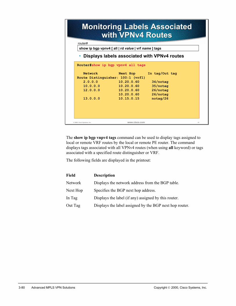
3-80 Advanced MPLS VPN Solutions Copyright 2000, Cisco Systems, Inc.
© 2000, Cisco Systems, Inc. www.cisco.com 81
show ip bgp vpnv4 [ all | rd value | vrf name ] tagsrouter#
• Displays labels associated with VPNv4 routes
Monitoring Labels Associatedwith VPNv4 Routes
Monitoring Labels Associatedwith VPNv4 Routes
Router#show ip bgp vpnv4 all tags Network Next Hop In tag/Out tagRoute Distinguisher: 100:1 (vrf1) 2.0.0.0 10.20.0.60 34/notag 10.0.0.0 10.20.0.60 35/notag 12.0.0.0 10.20.0.60 26/notag 10.20.0.60 26/notag 13.0.0.0 10.15.0.15 notag/26
The show ip bgp vnpv4 tags command can be used to display tags assigned tolocal or remote VRF routes by the local or remote PE router. The commanddisplays tags associated with all VPNv4 routes (when using all keyword) or tagsassociated with a specified route distinguisher or VRF.
The following fields are displayed in the printout:
Field Description
Network Displays the network address from the BGP table.
Next Hop Specifies the BGP next hop address.
In Tag Displays the label (if any) assigned by this router.
Out Tag Displays the label assigned by the BGP next hop router.
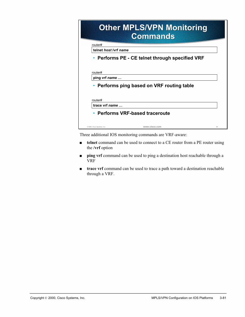
Copyright 2000, Cisco Systems, Inc. MPLS/VPN Configuration on IOS Platforms 3-81
© 2000, Cisco Systems, Inc. www.cisco.com 82
telnet host /vrf namerouter#
• Performs PE - CE telnet through specified VRF
Other MPLS/VPN MonitoringCommands
Other MPLS/VPN MonitoringCommands
ping vrf name …router#
• Performs ping based on VRF routing table
trace vrf name …router#
• Performs VRF-based traceroute
Three additional IOS monitoring commands are VRF-aware:
� telnet command can be used to connect to a CE router from a PE router usingthe /vrf option
� ping vrf command can be used to ping a destination host reachable through aVRF
� trace vrf command can be used to trace a path toward a destination reachablethrough a VRF.
3-82 Advanced MPLS VPN Solutions Copyright 2000, Cisco Systems, Inc.
SummaryA number of monitoring commands is available to support management andtroubleshooting of MPLS/VPN networks.
There are some well-known commands that perform the same task for the VRF asthey do for a normal router. They may also display some additional information.
There are also many new commands that are either MPLS or MPLS/VPN specific.
Review Questions� How would you verify the contents of a VRF routing table?
� How would you display an individual entry in a VRF CEF table?
� How would you display routing protocols running in a VRF?
� Why is the BGP protocol always running in every VRF?
� How would you inspect a label stack associated with a remote MPLS/VPNroute?
� How would you verify an VPNv4 information exchange with a MP-BGPneighbor?
� How would you display all routes with a specified route distinguisher?
� How would you display all labels associated with a VRF?
� Why do you only see labels for routes learned from CE routers?
� Would you ever see labels for routes received through MP-BGP in yourTFIB?

Copyright 2000, Cisco Systems, Inc. MPLS/VPN Configuration on IOS Platforms 3-83
Troubleshooting MPLS/VPN
ObjectivesUpon completion of this section, you will be able to perform the following tasks:
� Verify proper PE-to-PE connectivity
� Verify proper redistribution of VPN routes and creation of MPLS labels
� Verify VPN route propagation and data forwarding
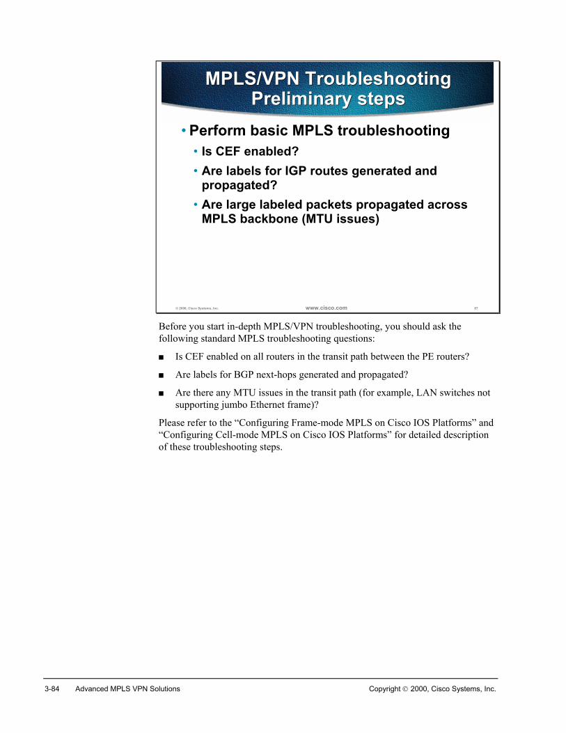
3-84 Advanced MPLS VPN Solutions Copyright 2000, Cisco Systems, Inc.
© 2000, Cisco Systems, Inc. www.cisco.com 87
MPLS/VPN TroubleshootingPreliminary steps
MPLS/VPN TroubleshootingPreliminary steps
• Perform basic MPLS troubleshooting• Is CEF enabled?• Are labels for IGP routes generated and
propagated?• Are large labeled packets propagated across
MPLS backbone (MTU issues)
Before you start in-depth MPLS/VPN troubleshooting, you should ask thefollowing standard MPLS troubleshooting questions:
� Is CEF enabled on all routers in the transit path between the PE routers?
� Are labels for BGP next-hops generated and propagated?
� Are there any MTU issues in the transit path (for example, LAN switches notsupporting jumbo Ethernet frame)?
Please refer to the “Configuring Frame-mode MPLS on Cisco IOS Platforms” and“Configuring Cell-mode MPLS on Cisco IOS Platforms” for detailed descriptionof these troubleshooting steps.
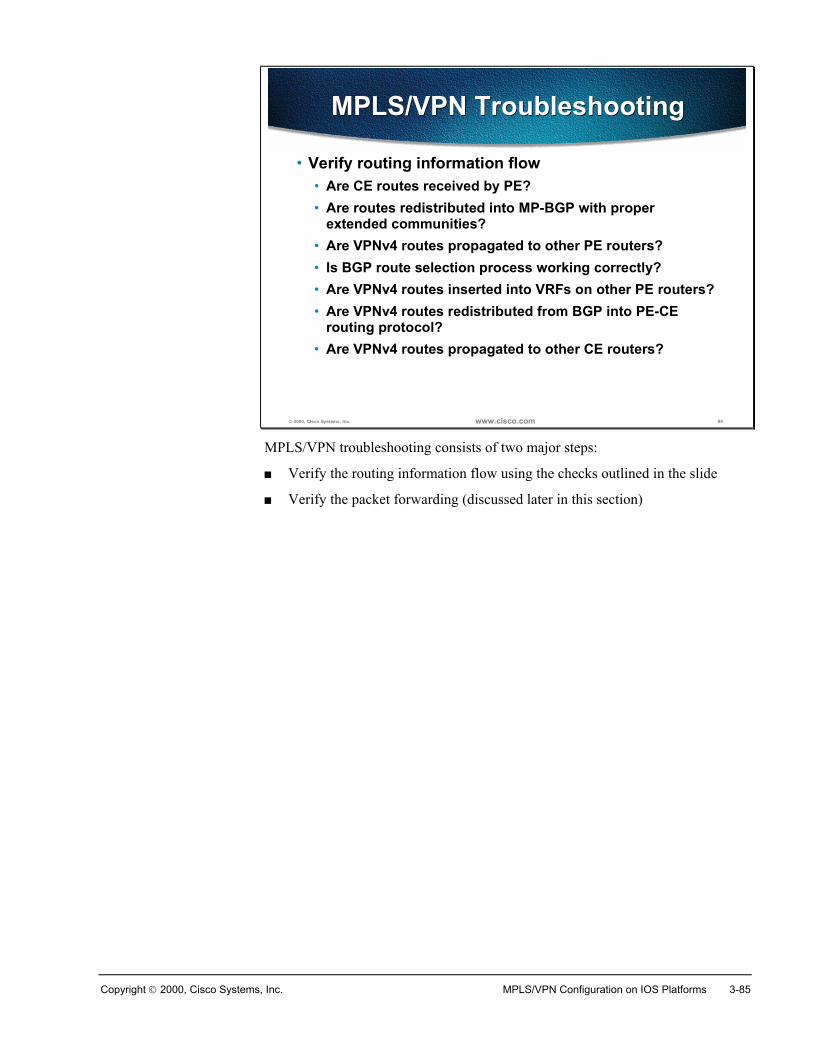
Copyright 2000, Cisco Systems, Inc. MPLS/VPN Configuration on IOS Platforms 3-85
© 2000, Cisco Systems, Inc. www.cisco.com 88
MPLS/VPN TroubleshootingMPLS/VPN Troubleshooting
• Verify routing information flow• Are CE routes received by PE?• Are routes redistributed into MP-BGP with proper
extended communities?• Are VPNv4 routes propagated to other PE routers?• Is BGP route selection process working correctly?• Are VPNv4 routes inserted into VRFs on other PE routers?• Are VPNv4 routes redistributed from BGP into PE-CE
routing protocol?• Are VPNv4 routes propagated to other CE routers?
MPLS/VPN troubleshooting consists of two major steps:
� Verify the routing information flow using the checks outlined in the slide
� Verify the packet forwarding (discussed later in this section)
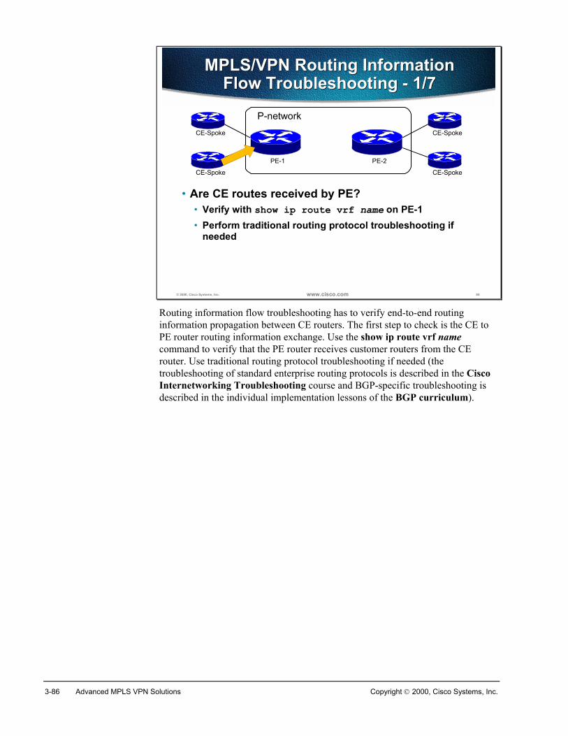
3-86 Advanced MPLS VPN Solutions Copyright 2000, Cisco Systems, Inc.
© 2000, Cisco Systems, Inc. www.cisco.com 89
MPLS/VPN Routing InformationFlow Troubleshooting - 1/7
MPLS/VPN Routing InformationFlow Troubleshooting - 1/7
• Are CE routes received by PE?• Verify with show ip route vrf name on PE-1• Perform traditional routing protocol troubleshooting if
needed
P-network
PE-1 PE-2
CE-Spoke
CE-Spoke
CE-Spoke
CE-Spoke
Routing information flow troubleshooting has to verify end-to-end routinginformation propagation between CE routers. The first step to check is the CE toPE router routing information exchange. Use the show ip route vrf namecommand to verify that the PE router receives customer routers from the CErouter. Use traditional routing protocol troubleshooting if needed (thetroubleshooting of standard enterprise routing protocols is described in the CiscoInternetworking Troubleshooting course and BGP-specific troubleshooting isdescribed in the individual implementation lessons of the BGP curriculum).
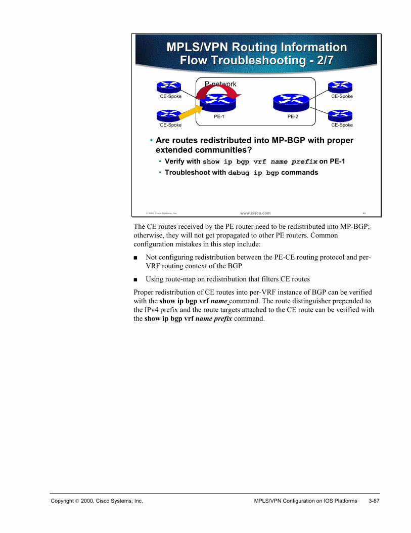
Copyright 2000, Cisco Systems, Inc. MPLS/VPN Configuration on IOS Platforms 3-87
© 2000, Cisco Systems, Inc. www.cisco.com 90
MPLS/VPN Routing InformationFlow Troubleshooting - 2/7
MPLS/VPN Routing InformationFlow Troubleshooting - 2/7
• Are routes redistributed into MP-BGP with properextended communities?• Verify with show ip bgp vrf name prefix on PE-1• Troubleshoot with debug ip bgp commands
P-network
PE-1 PE-2
CE-Spoke
CE-Spoke
CE-Spoke
CE-Spoke
The CE routes received by the PE router need to be redistributed into MP-BGP;otherwise, they will not get propagated to other PE routers. Commonconfiguration mistakes in this step include:
� Not configuring redistribution between the PE-CE routing protocol and per-VRF routing context of the BGP
� Using route-map on redistribution that filters CE routes
Proper redistribution of CE routes into per-VRF instance of BGP can be verifiedwith the show ip bgp vrf name command. The route distinguisher prepended tothe IPv4 prefix and the route targets attached to the CE route can be verified withthe show ip bgp vrf name prefix command.
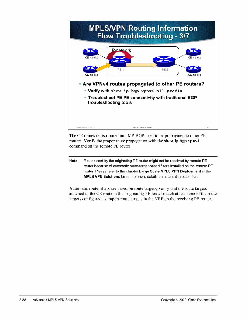
3-88 Advanced MPLS VPN Solutions Copyright 2000, Cisco Systems, Inc.
© 2000, Cisco Systems, Inc. www.cisco.com 91
MPLS/VPN Routing InformationFlow Troubleshooting - 3/7
MPLS/VPN Routing InformationFlow Troubleshooting - 3/7
• Are VPNv4 routes propagated to other PE routers?• Verify with show ip bgp vpnv4 all prefix• Troubleshoot PE-PE connectivity with traditional BGP
troubleshooting tools
P-network
PE-1 PE-2
CE-Spoke
CE-Spoke
CE-Spoke
CE-Spoke
The CE routes redistributed into MP-BGP need to be propagated to other PErouters. Verify the proper route propagation with the show ip bgp vpnv4command on the remote PE router.
Note Routes sent by the originating PE router might not be received by remote PErouter because of automatic route-target-based filters installed on the remote PErouter. Please refer to the chapter Large Scale MPLS VPN Deployment in theMPLS VPN Solutions lesson for more details on automatic route filters.
Automatic route filters are based on route targets; verify that the route targetsattached to the CE route in the originating PE router match at least one of the routetargets configured as import route targets in the VRF on the receiving PE router.
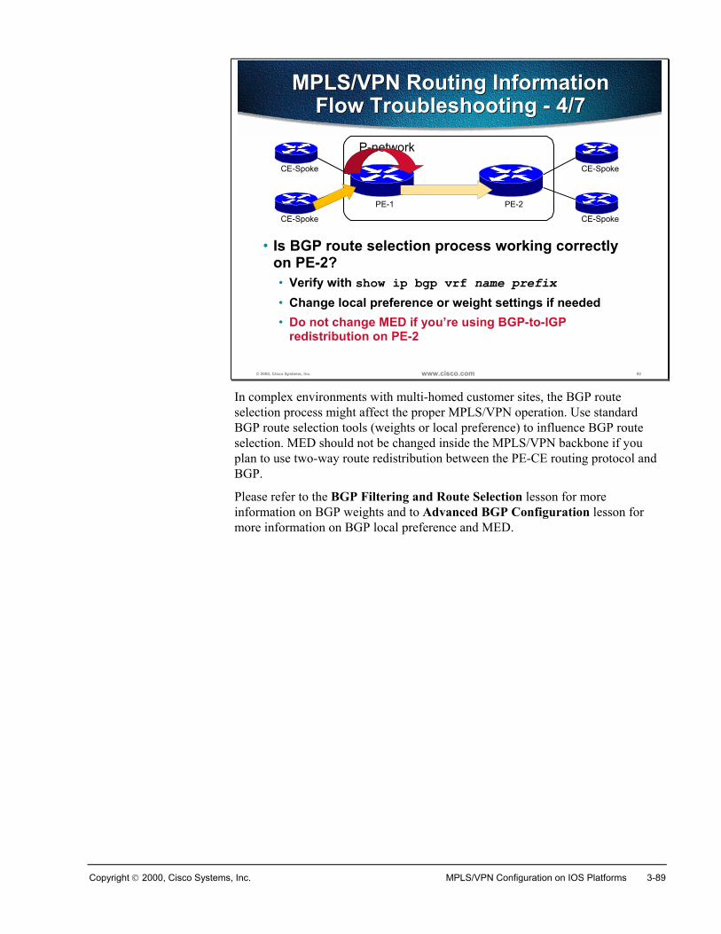
Copyright 2000, Cisco Systems, Inc. MPLS/VPN Configuration on IOS Platforms 3-89
© 2000, Cisco Systems, Inc. www.cisco.com 92
MPLS/VPN Routing InformationFlow Troubleshooting - 4/7
MPLS/VPN Routing InformationFlow Troubleshooting - 4/7
• Is BGP route selection process working correctlyon PE-2?• Verify with show ip bgp vrf name prefix• Change local preference or weight settings if needed• Do not change MED if you’re using BGP-to-IGP
redistribution on PE-2
P-network
PE-1 PE-2
CE-Spoke
CE-Spoke
CE-Spoke
CE-Spoke
In complex environments with multi-homed customer sites, the BGP routeselection process might affect the proper MPLS/VPN operation. Use standardBGP route selection tools (weights or local preference) to influence BGP routeselection. MED should not be changed inside the MPLS/VPN backbone if youplan to use two-way route redistribution between the PE-CE routing protocol andBGP.
Please refer to the BGP Filtering and Route Selection lesson for moreinformation on BGP weights and to Advanced BGP Configuration lesson formore information on BGP local preference and MED.
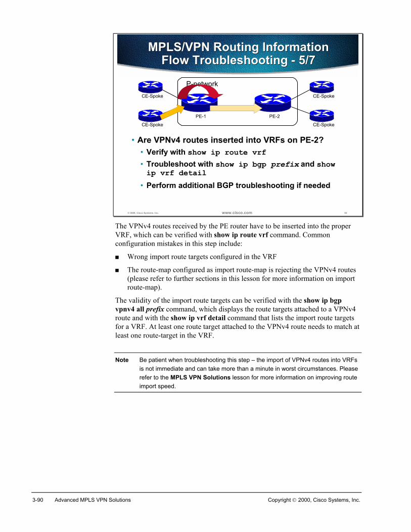
3-90 Advanced MPLS VPN Solutions Copyright 2000, Cisco Systems, Inc.
© 2000, Cisco Systems, Inc. www.cisco.com 93
MPLS/VPN Routing InformationFlow Troubleshooting - 5/7
MPLS/VPN Routing InformationFlow Troubleshooting - 5/7
• Are VPNv4 routes inserted into VRFs on PE-2?• Verify with show ip route vrf• Troubleshoot with show ip bgp prefix and showip vrf detail
• Perform additional BGP troubleshooting if needed
P-network
PE-1 PE-2
CE-Spoke
CE-Spoke
CE-Spoke
CE-Spoke
The VPNv4 routes received by the PE router have to be inserted into the properVRF, which can be verified with show ip route vrf command. Commonconfiguration mistakes in this step include:
� Wrong import route targets configured in the VRF
� The route-map configured as import route-map is rejecting the VPNv4 routes(please refer to further sections in this lesson for more information on importroute-map).
The validity of the import route targets can be verified with the show ip bgpvpnv4 all prefix command, which displays the route targets attached to a VPNv4route and with the show ip vrf detail command that lists the import route targetsfor a VRF. At least one route target attached to the VPNv4 route needs to match atleast one route-target in the VRF.
Note Be patient when troubleshooting this step – the import of VPNv4 routes into VRFsis not immediate and can take more than a minute in worst circumstances. Pleaserefer to the MPLS VPN Solutions lesson for more information on improving routeimport speed.

Copyright 2000, Cisco Systems, Inc. MPLS/VPN Configuration on IOS Platforms 3-91
© 2000, Cisco Systems, Inc. www.cisco.com 94
MPLS/VPN Routing InformationFlow Troubleshooting - 6/7
MPLS/VPN Routing InformationFlow Troubleshooting - 6/7
• Are VPNv4 routes redistributed from BGP into PE-CE routing protocol?• Verify redistribution configuration - is IGP metric
specified?• Perform traditional routing protocol troubleshooting
P-network
PE-1 PE-2
CE-Spoke
CE-Spoke
CE-Spoke
CE-Spoke
Finally, the BGP routes received via MP-BGP and inserted into the VRF need tobe redistributed into the PE-CE routing protocol. A number of commonredistribution mistakes sometimes occur here, starting with missing redistributionmetrics.
Please refer to the Building Scalable Cisco Networks (BSCN) and CiscoInternetworking Troubleshooting (CIT) courses for more information on routeredistribution troubleshooting.
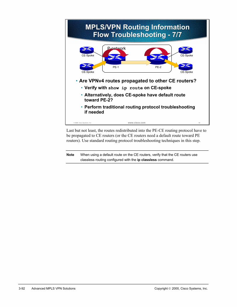
3-92 Advanced MPLS VPN Solutions Copyright 2000, Cisco Systems, Inc.
© 2000, Cisco Systems, Inc. www.cisco.com 95
MPLS/VPN Routing InformationFlow Troubleshooting - 7/7
MPLS/VPN Routing InformationFlow Troubleshooting - 7/7
• Are VPNv4 routes propagated to other CE routers?• Verify with show ip route on CE-spoke• Alternatively, does CE-spoke have default route
toward PE-2?• Perform traditional routing protocol troubleshooting
if needed
P-network
PE-1 PE-2
CE-Spoke
CE-Spoke
CE-Spoke
CE-Spoke
Last but not least, the routes redistributed into the PE-CE routing protocol have tobe propagated to CE routers (or the CE routers need a default route toward PErouters). Use standard routing protocol troubleshooting techniques in this step.
Note When using a default route on the CE routers, verify that the CE routers useclassless routing configured with the ip classless command.
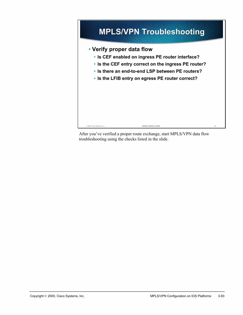
Copyright 2000, Cisco Systems, Inc. MPLS/VPN Configuration on IOS Platforms 3-93
© 2000, Cisco Systems, Inc. www.cisco.com 96
MPLS/VPN TroubleshootingMPLS/VPN Troubleshooting
• Verify proper data flow• Is CEF enabled on ingress PE router interface?• Is the CEF entry correct on the ingress PE router?• Is there an end-to-end LSP between PE routers?• Is the LFIB entry on egress PE router correct?
After you’ve verified a proper route exchange, start MPLS/VPN data flowtroubleshooting using the checks listed in the slide.
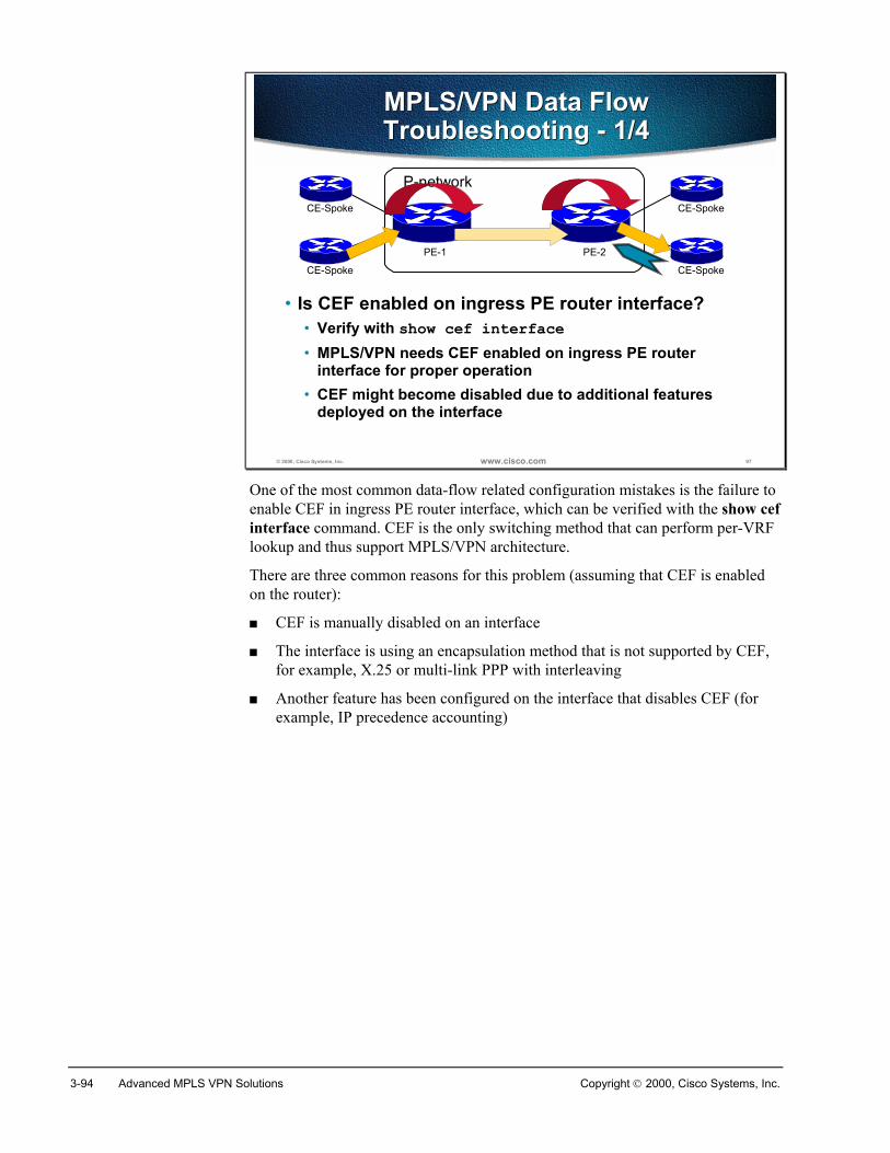
3-94 Advanced MPLS VPN Solutions Copyright 2000, Cisco Systems, Inc.
© 2000, Cisco Systems, Inc. www.cisco.com 97
MPLS/VPN Data FlowTroubleshooting - 1/4MPLS/VPN Data FlowTroubleshooting - 1/4
• Is CEF enabled on ingress PE router interface?• Verify with show cef interface• MPLS/VPN needs CEF enabled on ingress PE router
interface for proper operation• CEF might become disabled due to additional features
deployed on the interface
P-network
PE-1 PE-2
CE-Spoke
CE-Spoke
CE-Spoke
CE-Spoke
One of the most common data-flow related configuration mistakes is the failure toenable CEF in ingress PE router interface, which can be verified with the show cefinterface command. CEF is the only switching method that can perform per-VRFlookup and thus support MPLS/VPN architecture.
There are three common reasons for this problem (assuming that CEF is enabledon the router):
� CEF is manually disabled on an interface
� The interface is using an encapsulation method that is not supported by CEF,for example, X.25 or multi-link PPP with interleaving
� Another feature has been configured on the interface that disables CEF (forexample, IP precedence accounting)
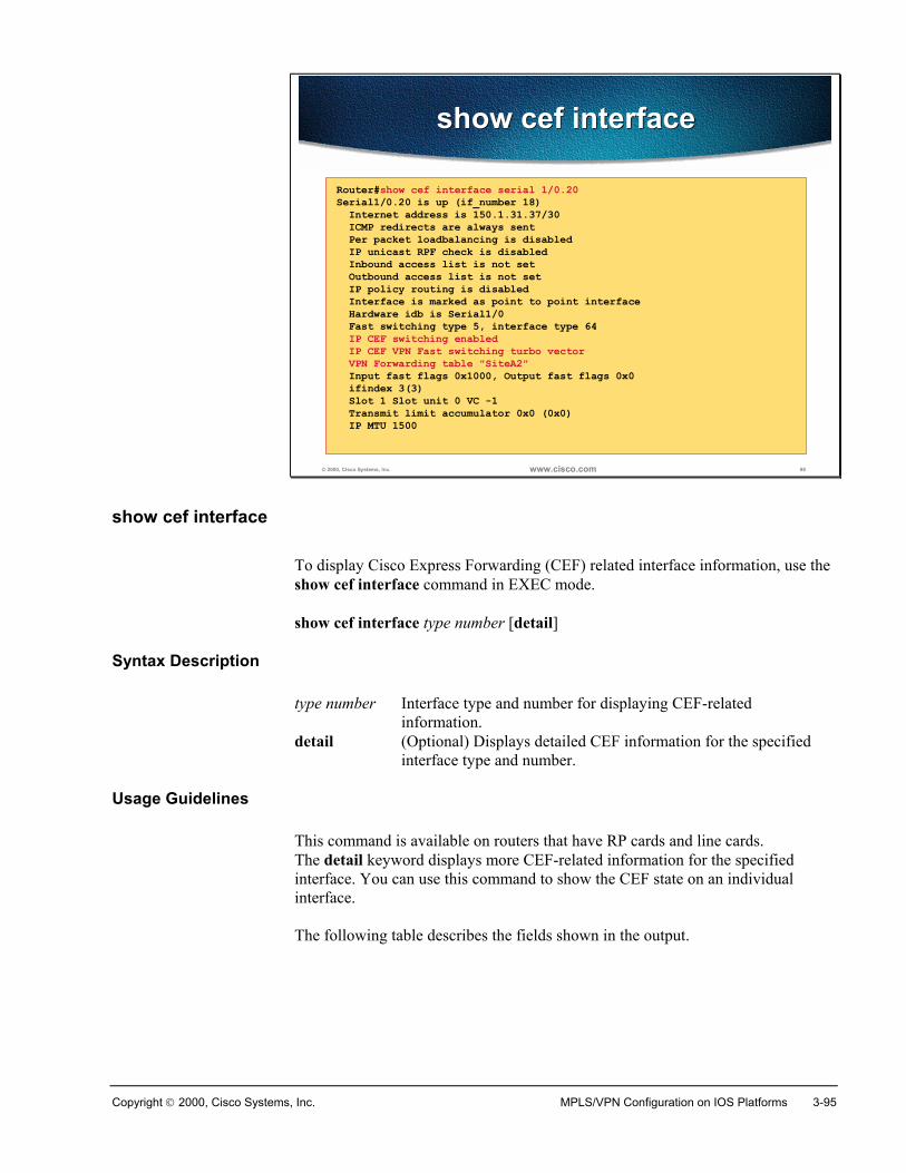
Copyright 2000, Cisco Systems, Inc. MPLS/VPN Configuration on IOS Platforms 3-95
© 2000, Cisco Systems, Inc. www.cisco.com 98
show cef interfaceshow cef interface
Router#show cef interface serial 1/0.20Serial1/0.20 is up (if_number 18) Internet address is 150.1.31.37/30 ICMP redirects are always sent Per packet loadbalancing is disabled IP unicast RPF check is disabled Inbound access list is not set Outbound access list is not set IP policy routing is disabled Interface is marked as point to point interface Hardware idb is Serial1/0 Fast switching type 5, interface type 64 IP CEF switching enabled IP CEF VPN Fast switching turbo vector VPN Forwarding table "SiteA2" Input fast flags 0x1000, Output fast flags 0x0 ifindex 3(3) Slot 1 Slot unit 0 VC -1 Transmit limit accumulator 0x0 (0x0) IP MTU 1500
show cef interface
To display Cisco Express Forwarding (CEF) related interface information, use theshow cef interface command in EXEC mode.
show cef interface type number [detail]
Syntax Description
type number Interface type and number for displaying CEF-relatedinformation.
detail (Optional) Displays detailed CEF information for the specifiedinterface type and number.
Usage Guidelines
This command is available on routers that have RP cards and line cards.The detail keyword displays more CEF-related information for the specifiedinterface. You can use this command to show the CEF state on an individualinterface.
The following table describes the fields shown in the output.
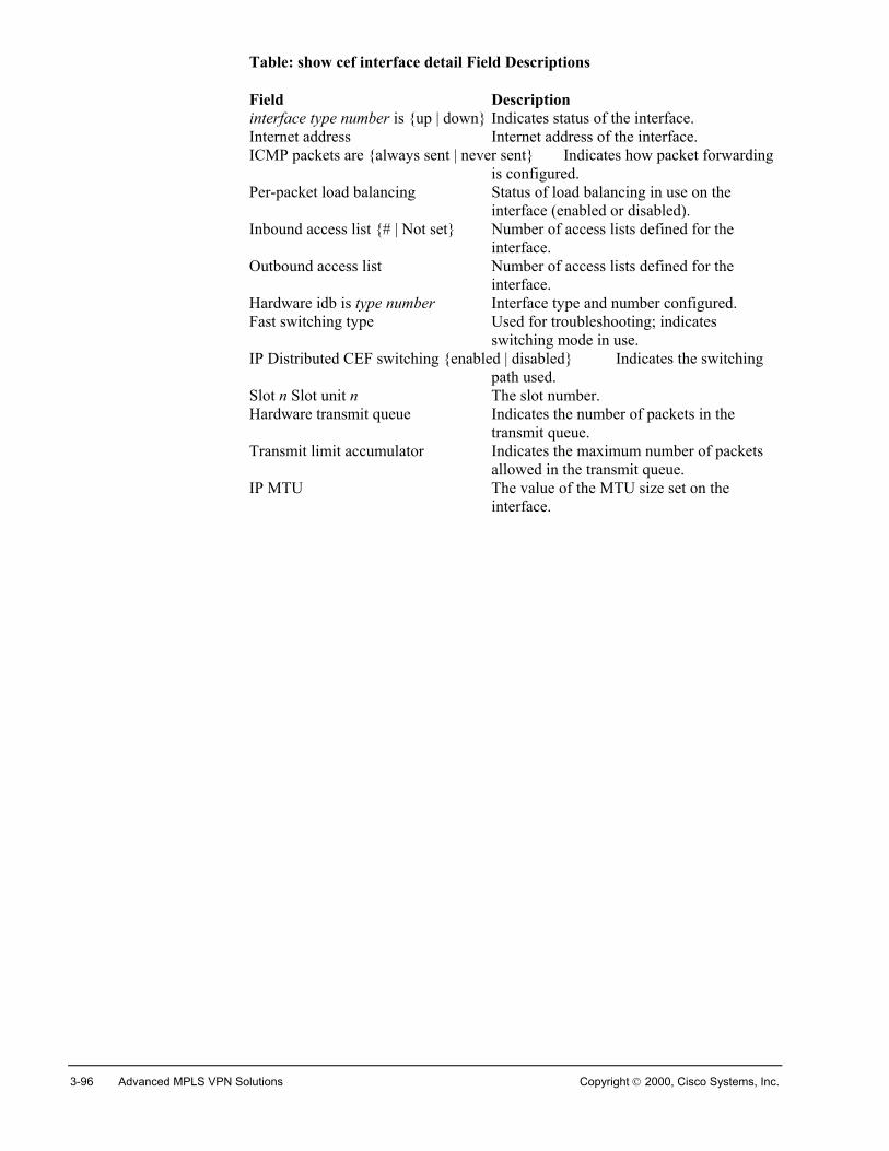
3-96 Advanced MPLS VPN Solutions Copyright 2000, Cisco Systems, Inc.
Table: show cef interface detail Field Descriptions
Field Description interface type number is {up | down} Indicates status of the interface.Internet address Internet address of the interface.ICMP packets are {always sent | never sent} Indicates how packet forwarding
is configured.Per-packet load balancing Status of load balancing in use on the
interface (enabled or disabled).Inbound access list {# | Not set} Number of access lists defined for the
interface.Outbound access list Number of access lists defined for the
interface.Hardware idb is type number Interface type and number configured.Fast switching type Used for troubleshooting; indicates
switching mode in use.IP Distributed CEF switching {enabled | disabled} Indicates the switching
path used.Slot n Slot unit n The slot number.Hardware transmit queue Indicates the number of packets in the
transmit queue.Transmit limit accumulator Indicates the maximum number of packets
allowed in the transmit queue.IP MTU The value of the MTU size set on the
interface.
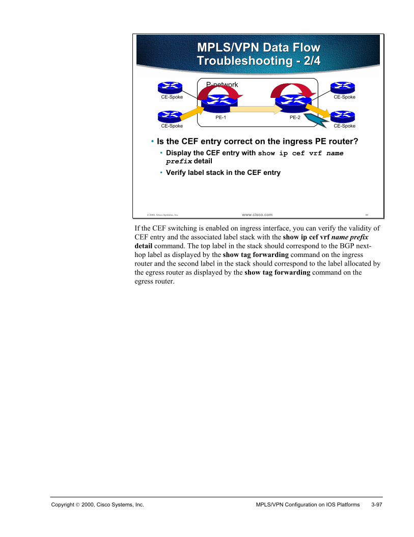
Copyright 2000, Cisco Systems, Inc. MPLS/VPN Configuration on IOS Platforms 3-97
© 2000, Cisco Systems, Inc. www.cisco.com 99
MPLS/VPN Data FlowTroubleshooting - 2/4MPLS/VPN Data FlowTroubleshooting - 2/4
• Is the CEF entry correct on the ingress PE router?• Display the CEF entry with show ip cef vrf nameprefix detail
• Verify label stack in the CEF entry
P-network
PE-1 PE-2
CE-Spoke
CE-Spoke
CE-Spoke
CE-Spoke
If the CEF switching is enabled on ingress interface, you can verify the validity ofCEF entry and the associated label stack with the show ip cef vrf name prefixdetail command. The top label in the stack should correspond to the BGP next-hop label as displayed by the show tag forwarding command on the ingressrouter and the second label in the stack should correspond to the label allocated bythe egress router as displayed by the show tag forwarding command on theegress router.
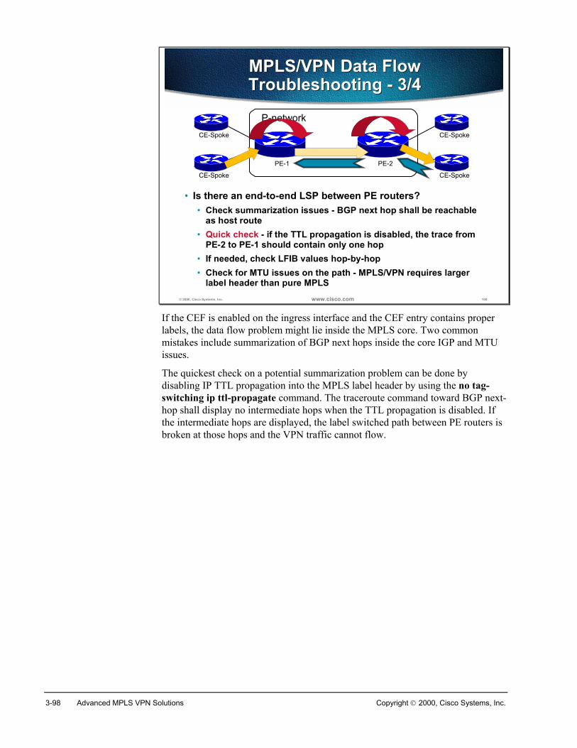
3-98 Advanced MPLS VPN Solutions Copyright 2000, Cisco Systems, Inc.
© 2000, Cisco Systems, Inc. www.cisco.com 100
MPLS/VPN Data FlowTroubleshooting - 3/4MPLS/VPN Data FlowTroubleshooting - 3/4
• Is there an end-to-end LSP between PE routers?• Check summarization issues - BGP next hop shall be reachable
as host route• Quick check - if the TTL propagation is disabled, the trace from
PE-2 to PE-1 should contain only one hop• If needed, check LFIB values hop-by-hop• Check for MTU issues on the path - MPLS/VPN requires larger
label header than pure MPLS
P-network
PE-1 PE-2
CE-Spoke
CE-Spoke
CE-Spoke
CE-Spoke
If the CEF is enabled on the ingress interface and the CEF entry contains properlabels, the data flow problem might lie inside the MPLS core. Two commonmistakes include summarization of BGP next hops inside the core IGP and MTUissues.
The quickest check on a potential summarization problem can be done bydisabling IP TTL propagation into the MPLS label header by using the no tag-switching ip ttl-propagate command. The traceroute command toward BGP next-hop shall display no intermediate hops when the TTL propagation is disabled. Ifthe intermediate hops are displayed, the label switched path between PE routers isbroken at those hops and the VPN traffic cannot flow.

Copyright 2000, Cisco Systems, Inc. MPLS/VPN Configuration on IOS Platforms 3-99
© 2000, Cisco Systems, Inc. www.cisco.com 101
MPLS/VPN Data FlowTroubleshooting - 4/4MPLS/VPN Data FlowTroubleshooting - 4/4
• Is the LFIB entry on egress PE router correct?• Find out the second label in the label stack on PE-2 withshow ip cef vrf name prefix detail
• Verify correctness of LFIB entry on PE-1 with show tagforwarding vrf name tag value detail
P-network
PE-1 PE-2
CE-Spoke
CE-Spoke
CE-Spoke
CE-Spoke
As a last troubleshooting measure (usually not needed), you can verify thecontents of Label Forwarding Information Base (LFIB) on the egress PE routerand compare it with the second label in the label stack on the ingress PE router. Amismatch indicates an internal IOS error that has to be reported to Cisco TechnicalAssistance Center (TAC).
3-100 Advanced MPLS VPN Solutions Copyright 2000, Cisco Systems, Inc.
SummaryTo verify the proper operation of the MPLS/VPN network first perform theinternal connectivity tests within the core network by pinging between theloopbacks of the PE routers. Make sure that ICMP packets were label-switched. Inthe second step you should verify the propagation of customer networks throughMP-BGP and installation of VPN labels into the forwarding table. Pingingbetween the CE routers should confirm that the VPN is functional.
Review Questions� What are the preliminary MPLS/VPN troubleshooting steps?
� How would you verify routing information exchange between PE routers?
� How would you verify that the VPNv4 routes are entered in the proper VRF?
� How would you verify redistribution of VPNv4 routes into the PE-CE routingprotocol?
� How would you test end-to-end data flow between PE routers?
� How would you verify that the CE routes get redistributed into MP-BGP withproper route targets?
� How would you check for potential MTU size issues on the path taken by PE-to-PE LSP?
� How would you verify that the PE router ingress interface supports CEFswitching?
Copyright 2000, Cisco Systems, Inc. MPLS/VPN Configuration on IOS Platforms 3-101
Advanced VRF Import/Export Features
ObjectivesUpon completion of this section, you will be able to perform the following tasks:
� Configure import and export route maps within VRFs
� Configure limits on number of routes accepted from a BGP neighbor
� Configure limits on total number of routes in a VRF
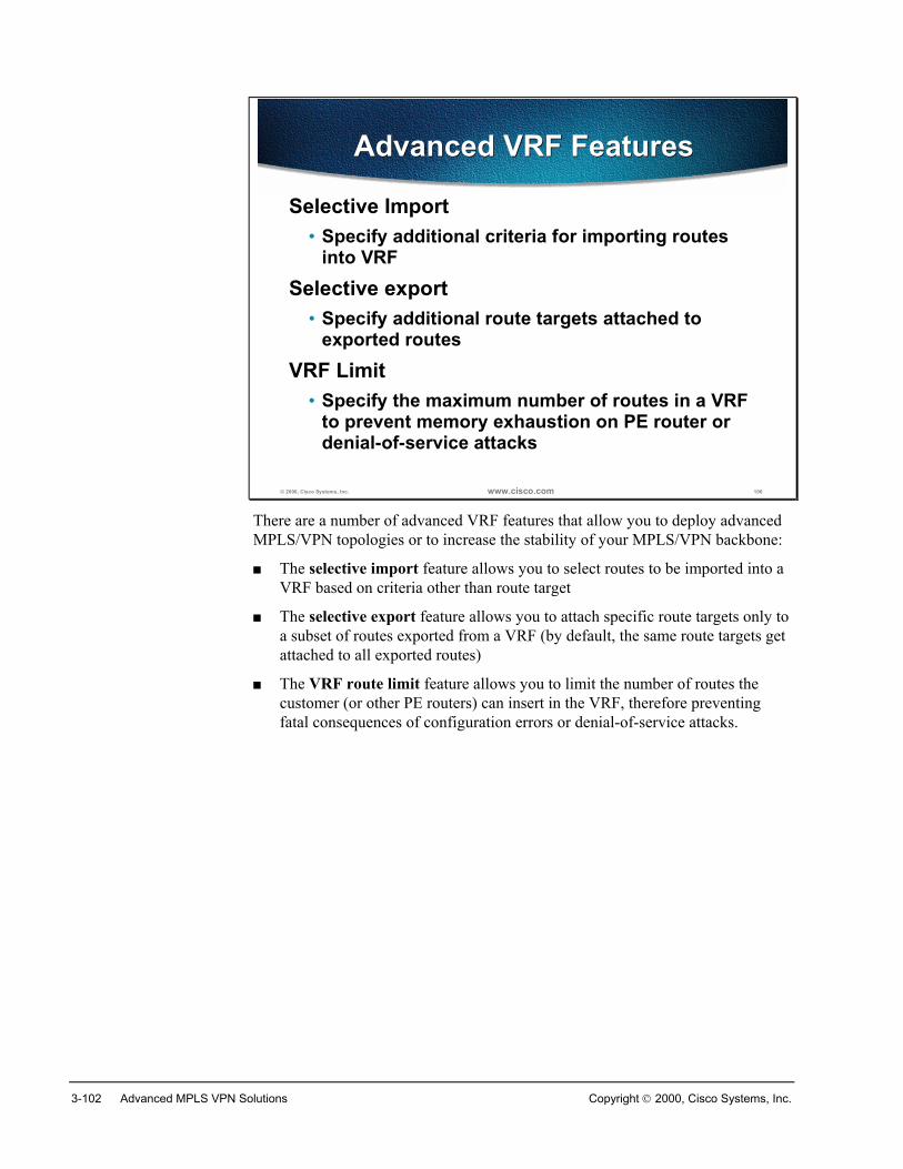
3-102 Advanced MPLS VPN Solutions Copyright 2000, Cisco Systems, Inc.
© 2000, Cisco Systems, Inc. www.cisco.com 106
Advanced VRF FeaturesAdvanced VRF Features
Selective Import• Specify additional criteria for importing routes
into VRFSelective export
• Specify additional route targets attached toexported routes
VRF Limit• Specify the maximum number of routes in a VRF
to prevent memory exhaustion on PE router ordenial-of-service attacks
There are a number of advanced VRF features that allow you to deploy advancedMPLS/VPN topologies or to increase the stability of your MPLS/VPN backbone:
� The selective import feature allows you to select routes to be imported into aVRF based on criteria other than route target
� The selective export feature allows you to attach specific route targets only toa subset of routes exported from a VRF (by default, the same route targets getattached to all exported routes)
� The VRF route limit feature allows you to limit the number of routes thecustomer (or other PE routers) can insert in the VRF, therefore preventingfatal consequences of configuration errors or denial-of-service attacks.
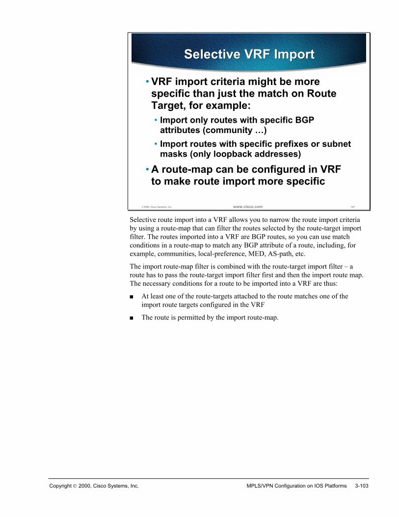
Copyright 2000, Cisco Systems, Inc. MPLS/VPN Configuration on IOS Platforms 3-103
© 2000, Cisco Systems, Inc. www.cisco.com 107
Selective VRF ImportSelective VRF Import
• VRF import criteria might be morespecific than just the match on RouteTarget, for example:• Import only routes with specific BGP
attributes (community …)• Import routes with specific prefixes or subnet
masks (only loopback addresses)
• A route-map can be configured in VRFto make route import more specific
Selective route import into a VRF allows you to narrow the route import criteriaby using a route-map that can filter the routes selected by the route-target importfilter. The routes imported into a VRF are BGP routes, so you can use matchconditions in a route-map to match any BGP attribute of a route, including, forexample, communities, local-preference, MED, AS-path, etc.
The import route-map filter is combined with the route-target import filter – aroute has to pass the route-target import filter first and then the import route map.The necessary conditions for a route to be imported into a VRF are thus:
� At least one of the route-targets attached to the route matches one of theimport route targets configured in the VRF
� The route is permitted by the import route-map.
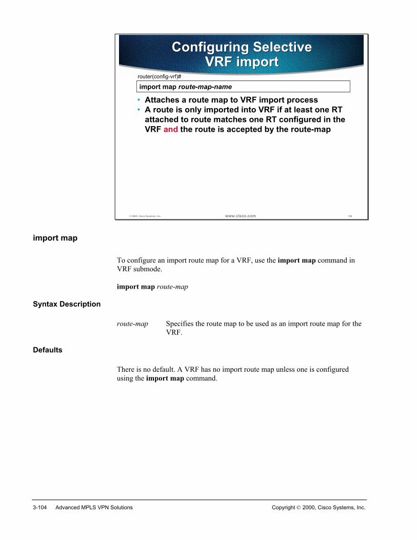
3-104 Advanced MPLS VPN Solutions Copyright 2000, Cisco Systems, Inc.
© 2000, Cisco Systems, Inc. www.cisco.com 108
Configuring SelectiveVRF import
Configuring SelectiveVRF import
import map route-map-namerouter(config-vrf)#
• Attaches a route map to VRF import process• A route is only imported into VRF if at least one RT
attached to route matches one RT configured in theVRF and the route is accepted by the route-map
import map
To configure an import route map for a VRF, use the import map command inVRF submode.
import map route-map
Syntax Description
route-map Specifies the route map to be used as an import route map for theVRF.
Defaults
There is no default. A VRF has no import route map unless one is configuredusing the import map command.
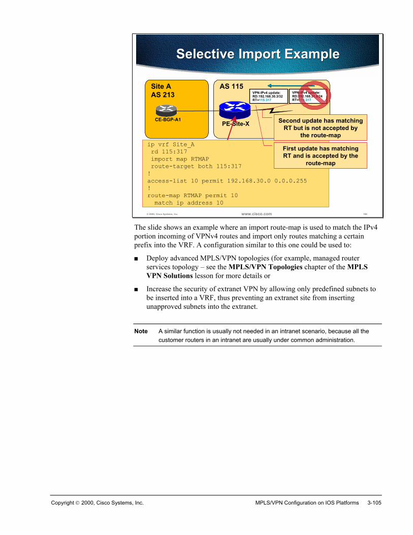
Copyright 2000, Cisco Systems, Inc. MPLS/VPN Configuration on IOS Platforms 3-105
© 2000, Cisco Systems, Inc. www.cisco.com 109
Selective Import ExampleSelective Import Example
Site AAS 213
AS 115
CE-BGP-A1PE-Site-X
VPN-IPv4 update:RD:192.168.31.0/24RT=115:317
ip vrf Site_A rd 115:317 import map RTMAP route-target both 115:317!access-list 10 permit 192.168.30.0 0.0.0.255!route-map RTMAP permit 10 match ip address 10
VPN-IPv4 update:RD:192.168.30.3/32RT=115:317
First update has matchingRT and is accepted by the
route-map
Second update has matchingRT but is not accepted by
the route-map
The slide shows an example where an import route-map is used to match the IPv4portion incoming of VPNv4 routes and import only routes matching a certainprefix into the VRF. A configuration similar to this one could be used to:
� Deploy advanced MPLS/VPN topologies (for example, managed routerservices topology – see the MPLS/VPN Topologies chapter of the MPLSVPN Solutions lesson for more details or
� Increase the security of extranet VPN by allowing only predefined subnets tobe inserted into a VRF, thus preventing an extranet site from insertingunapproved subnets into the extranet.
Note A similar function is usually not needed in an intranet scenario, because all thecustomer routers in an intranet are usually under common administration.
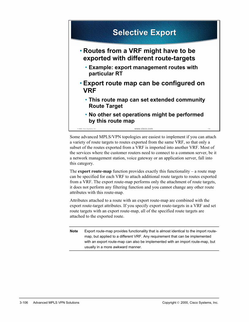
3-106 Advanced MPLS VPN Solutions Copyright 2000, Cisco Systems, Inc.
© 2000, Cisco Systems, Inc. www.cisco.com 110
Selective ExportSelective Export
• Routes from a VRF might have to beexported with different route-targets• Example: export management routes with
particular RT
• Export route map can be configured onVRF• This route map can set extended community
Route Target• No other set operations might be performed
by this route map
Some advanced MPLS/VPN topologies are easiest to implement if you can attacha variety of route targets to routes exported from the same VRF, so that only asubset of the routes exported from a VRF is imported into another VRF. Most ofthe services where the customer routers need to connect to a common server, be ita network management station, voice gateway or an application server, fall intothis category.
The export route-map function provides exactly this functionality – a route mapcan be specified for each VRF to attach additional route targets to routes exportedfrom a VRF. The export route-map performs only the attachment of route targets,it does not perform any filtering function and you cannot change any other routeattributes with this route-map.
Attributes attached to a route with an export route-map are combined with theexport route-target attributes. If you specify export route-targets in a VRF and setroute targets with an export route-map, all of the specified route targets areattached to the exported route.
Note Export route-map provides functionality that is almost identical to the import route-map, but applied to a different VRF. Any requirement that can be implementedwith an export route-map can also be implemented with an import route-map, butusually in a more awkward manner.
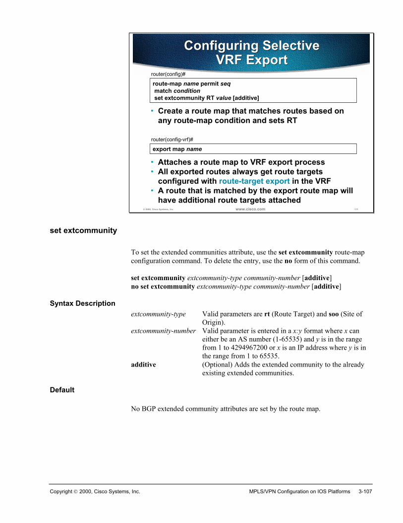
Copyright 2000, Cisco Systems, Inc. MPLS/VPN Configuration on IOS Platforms 3-107
© 2000, Cisco Systems, Inc. www.cisco.com 111
route-map name permit seq match condition set extcommunity RT value [additive]
router(config)#
• Create a route map that matches routes based onany route-map condition and sets RT
Configuring SelectiveVRF Export
Configuring SelectiveVRF Export
export map namerouter(config-vrf)#
• Attaches a route map to VRF export process• All exported routes always get route targets
configured with route-target export in the VRF• A route that is matched by the export route map will
have additional route targets attached
set extcommunity
To set the extended communities attribute, use the set extcommunity route-mapconfiguration command. To delete the entry, use the no form of this command.
set extcommunity extcommunity-type community-number [additive]no set extcommunity extcommunity-type community-number [additive]
Syntax Descriptionextcommunity-type Valid parameters are rt (Route Target) and soo (Site of
Origin). extcommunity-number Valid parameter is entered in a x:y format where x can
either be an AS number (1-65535) and y is in the rangefrom 1 to 4294967200 or x is an IP address where y is inthe range from 1 to 65535.
additive (Optional) Adds the extended community to the alreadyexisting extended communities.
Default
No BGP extended community attributes are set by the route map.
3-108 Advanced MPLS VPN Solutions Copyright 2000, Cisco Systems, Inc.
export map
To apply a route map to filter and modify exported routes, use the export mapVRF configuration command. To remove the route map from the VRF, use the noform of this command.
export map route-map-nameno export map route-map-name
Syntax Description
route-map-name specify the name of the route map to be used.
Default
No route map is used.
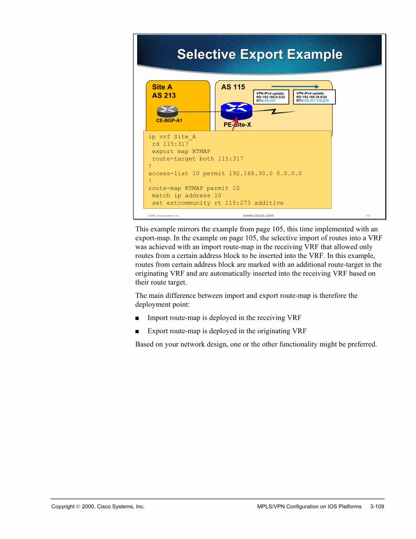
Copyright 2000, Cisco Systems, Inc. MPLS/VPN Configuration on IOS Platforms 3-109
© 2000, Cisco Systems, Inc. www.cisco.com 112
Selective Export ExampleSelective Export Example
Site AAS 213
AS 115
CE-BGP-A1PE-Site-X
ip vrf Site_A rd 115:317 export map RTMAP route-target both 115:317!access-list 10 permit 192.168.30.0 0.0.0.0!route-map RTMAP permit 10 match ip address 10 set extcommunity rt 115:273 additive
VPN-IPv4 update:RD:192.168.0.5/32RT=115:317
VPN-IPv4 update:RD:192.168.30.0/24RT=115:317 115:273
This example mirrors the example from page 105, this time implemented with anexport-map. In the example on page 105, the selective import of routes into a VRFwas achieved with an import route-map in the receiving VRF that allowed onlyroutes from a certain address block to be inserted into the VRF. In this example,routes from certain address block are marked with an additional route-target in theoriginating VRF and are automatically inserted into the receiving VRF based ontheir route target.
The main difference between import and export route-map is therefore thedeployment point:
� Import route-map is deployed in the receiving VRF
� Export route-map is deployed in the originating VRF
Based on your network design, one or the other functionality might be preferred.
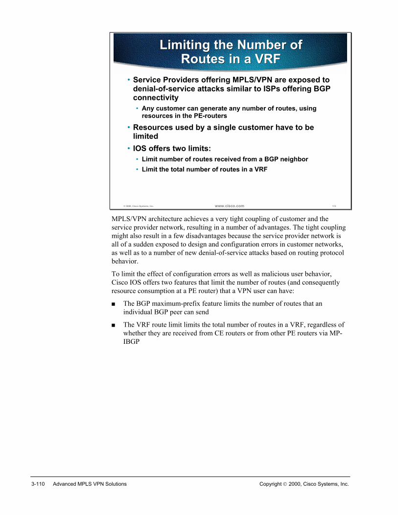
3-110 Advanced MPLS VPN Solutions Copyright 2000, Cisco Systems, Inc.
© 2000, Cisco Systems, Inc. www.cisco.com 113
Limiting the Number ofRoutes in a VRF
Limiting the Number ofRoutes in a VRF
• Service Providers offering MPLS/VPN are exposed todenial-of-service attacks similar to ISPs offering BGPconnectivity• Any customer can generate any number of routes, using
resources in the PE-routers
• Resources used by a single customer have to belimited
• IOS offers two limits:• Limit number of routes received from a BGP neighbor• Limit the total number of routes in a VRF
MPLS/VPN architecture achieves a very tight coupling of customer and theservice provider network, resulting in a number of advantages. The tight couplingmight also result in a few disadvantages because the service provider network isall of a sudden exposed to design and configuration errors in customer networks,as well as to a number of new denial-of-service attacks based on routing protocolbehavior.
To limit the effect of configuration errors as well as malicious user behavior,Cisco IOS offers two features that limit the number of routes (and consequentlyresource consumption at a PE router) that a VPN user can have:
� The BGP maximum-prefix feature limits the number of routes that anindividual BGP peer can send
� The VRF route limit limits the total number of routes in a VRF, regardless ofwhether they are received from CE routers or from other PE routers via MP-IBGP
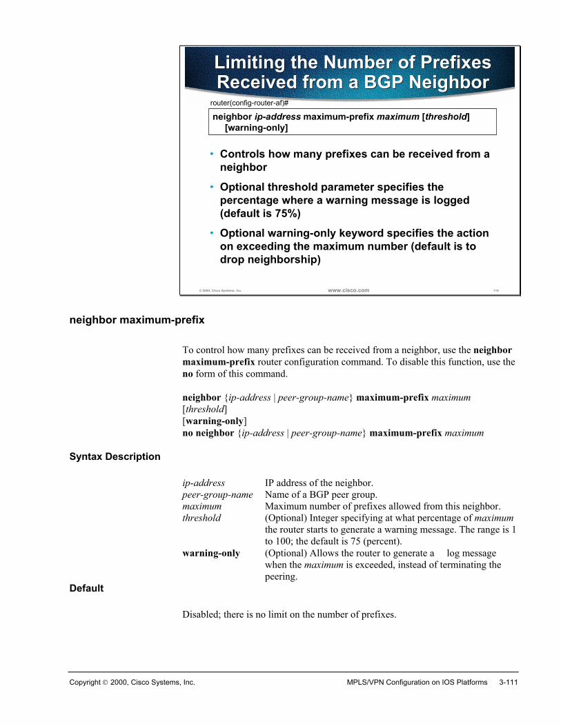
Copyright 2000, Cisco Systems, Inc. MPLS/VPN Configuration on IOS Platforms 3-111
© 2000, Cisco Systems, Inc. www.cisco.com 114
Limiting the Number of PrefixesReceived from a BGP NeighborLimiting the Number of PrefixesReceived from a BGP Neighbor
neighbor ip-address maximum-prefix maximum [threshold][warning-only]
router(config-router-af)#
• Controls how many prefixes can be received from aneighbor
• Optional threshold parameter specifies thepercentage where a warning message is logged(default is 75%)
• Optional warning-only keyword specifies the actionon exceeding the maximum number (default is todrop neighborship)
neighbor maximum-prefix
To control how many prefixes can be received from a neighbor, use the neighbormaximum-prefix router configuration command. To disable this function, use theno form of this command.
neighbor {ip-address | peer-group-name} maximum-prefix maximum[threshold][warning-only]no neighbor {ip-address | peer-group-name} maximum-prefix maximum
Syntax Description
ip-address IP address of the neighbor.peer-group-name Name of a BGP peer group.maximum Maximum number of prefixes allowed from this neighbor.threshold (Optional) Integer specifying at what percentage of maximum
the router starts to generate a warning message. The range is 1to 100; the default is 75 (percent).
warning-only (Optional) Allows the router to generate a log messagewhen the maximum is exceeded, instead of terminating thepeering.
Default
Disabled; there is no limit on the number of prefixes.
3-112 Advanced MPLS VPN Solutions Copyright 2000, Cisco Systems, Inc.
© 2000, Cisco Systems, Inc. www.cisco.com 115
VRF Route LimitVRF Route Limit
• The VRF route-limit limits the number ofroutes that are imported into a VRF• Routes coming from CE routers• Routes coming from other PEs (imported routes)
• The route limit is configured for each VRF• If the number of routes exceeds the route-limit
• Syslog message is generated• (Optional) routes are not inserted into VRF
anymore
The VRF route limit, contrary to the BGP maximum-prefix limit, limits the overallnumber of routes in a VRF, regardless of their origin. Similar to BGP maximum-prefix, the network operator might be warned when the number of routes exceedsa certain threshold via the syslog mechanism. Additionally, you can configure IOSto ignore new VRF routes when the total number of routes exceeds the maximumconfigured limit.
The route limit is configured for each individual VRF, giving you maximumdesign and configuration flexibility.
Note The per-VRF limit could be used to implement add-on MPLS/VPN services, wherea user paying for a better service might be able to insert more VPN routes into thenetwork.
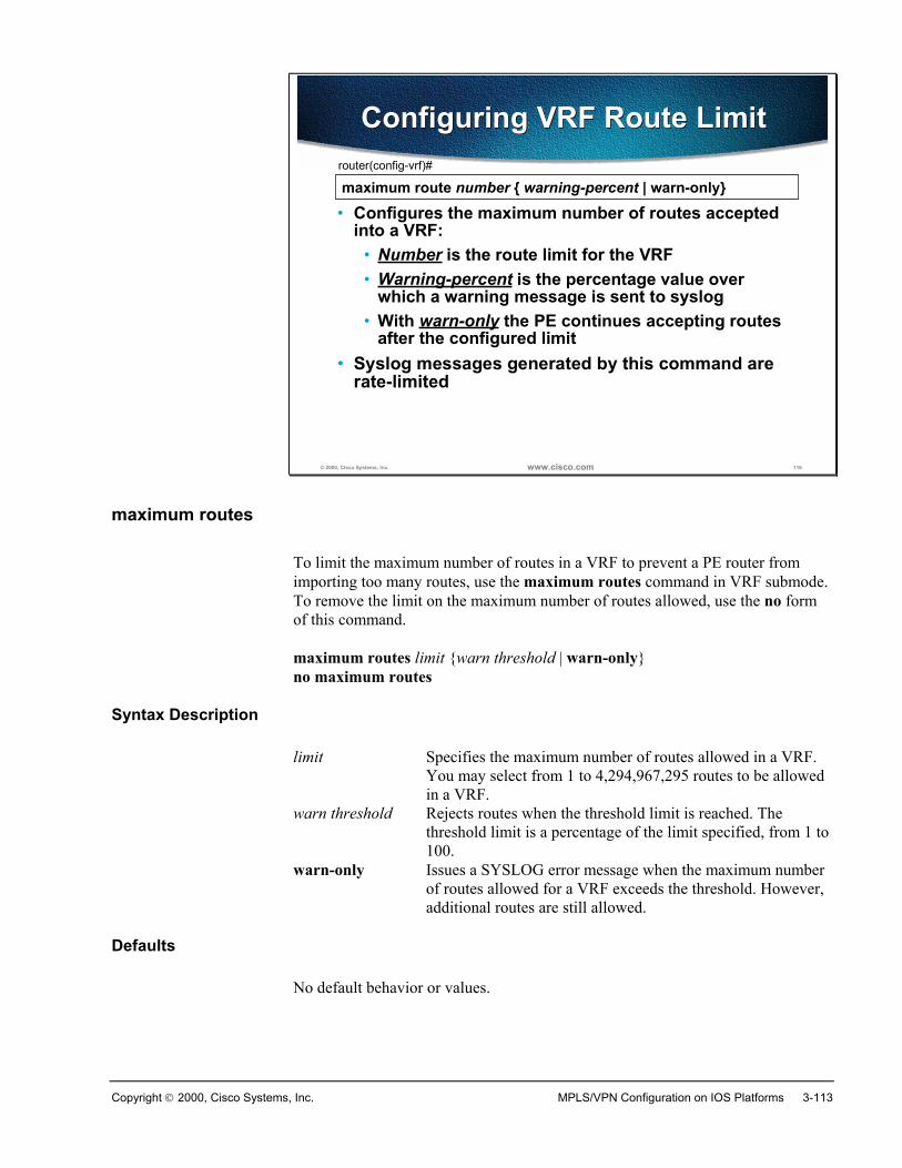
Copyright 2000, Cisco Systems, Inc. MPLS/VPN Configuration on IOS Platforms 3-113
© 2000, Cisco Systems, Inc. www.cisco.com 116
Configuring VRF Route LimitConfiguring VRF Route Limit
maximum route number { warning-percent | warn-only}router(config-vrf)#
• Configures the maximum number of routes acceptedinto a VRF:
• Number is the route limit for the VRF• Warning-percent is the percentage value over
which a warning message is sent to syslog• With warn-only the PE continues accepting routes
after the configured limit• Syslog messages generated by this command are
rate-limited
maximum routes
To limit the maximum number of routes in a VRF to prevent a PE router fromimporting too many routes, use the maximum routes command in VRF submode.To remove the limit on the maximum number of routes allowed, use the no formof this command.
maximum routes limit {warn threshold | warn-only}no maximum routes
Syntax Description
limit Specifies the maximum number of routes allowed in a VRF.You may select from 1 to 4,294,967,295 routes to be allowedin a VRF.
warn threshold Rejects routes when the threshold limit is reached. Thethreshold limit is a percentage of the limit specified, from 1 to100.
warn-only Issues a SYSLOG error message when the maximum numberof routes allowed for a VRF exceeds the threshold. However,additional routes are still allowed.
Defaults
No default behavior or values.
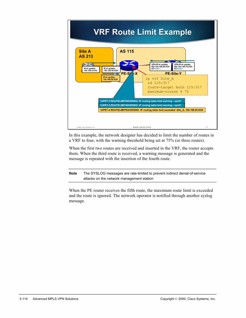
3-114 Advanced MPLS VPN Solutions Copyright 2000, Cisco Systems, Inc.
© 2000, Cisco Systems, Inc. www.cisco.com 117
VRF Route Limit ExampleVRF Route Limit Example
Site AAS 213
AS 115
CE-BGP-A1PE-Site-X PE-Site-Y
IPv4 update:192.168.0.5/32
IPv4 update:192.168.50.0/24
VPN-IPv4 update:RD:192.168.60.0/24RT=100:1
IPv4 update:192.168.55.0/24
%IPRT-3-ROUTELIMITWARNING: IP routing table limit warning - vpn01
VPN-IPv4 update:RD:192.168.70.0/24RT=100:1
%IPRT-3-ROUTELIMITWARNING: IP routing table limit warning - vpn01
%IPRT-3-ROUTELIMITEXCEEDED: IP routing table limit exceeded -Site_A, 192.168.55.0/24
ip vrf Site_A rd 115:317 route-target both 115:317 maximum-routes 4 75
In this example, the network designer has decided to limit the number of routes ina VRF to four, with the warning threshold being set at 75% (or three routes).
When the first two routes are received and inserted in the VRF, the router acceptsthem. When the third route is received, a warning message is generated and themessage is repeated with the insertion of the fourth route.
Note The SYSLOG messages are rate-limited to prevent indirect denial-of-serviceattacks on the network management station
When the PE router receives the fifth route, the maximum route limit is exceededand the route is ignored. The network operator is notified through another syslogmessage.
Copyright 2000, Cisco Systems, Inc. MPLS/VPN Configuration on IOS Platforms 3-115
SummaryRoute maps can be used to filter routes to be imported and exported. Route mapsused to import routes can match on standard and extended BGP parameters. Routemaps used to export routes can match on standard BGP parameters.
To prevent CE routers from flooding the PE routers with excessive number ofroutes, a limit can be set on the number of updates accepted from BGP neighbors.
A limit can also be set for the number of routing entries in the VRF.
Review Questions� Why would you need selective VRF import?
� How does the import route-map affect VRF import process?
� Why would you need selective VRF export?
� How does the export route-map affect VRF export process?
� Which BGP attributes can be set with an export route-map?
� Why would you need VRF route limit?
� How many VRF route-limiting options does IOS offer?
� When would you want to use BGP maximum-prefix parameter?
� When would you want to use VRF route-limit?
3-116 Advanced MPLS VPN Solutions Copyright 2000, Cisco Systems, Inc.
Advanced PE-CE BGP Configuration
ObjectivesUpon completion of this section, you will be able to perform the following tasks:
� Use the AS-Override feature
� Use the Allowas-in feature
� Configure Site-Of-Origin (SOO) on incoming interface or BGP neighbor
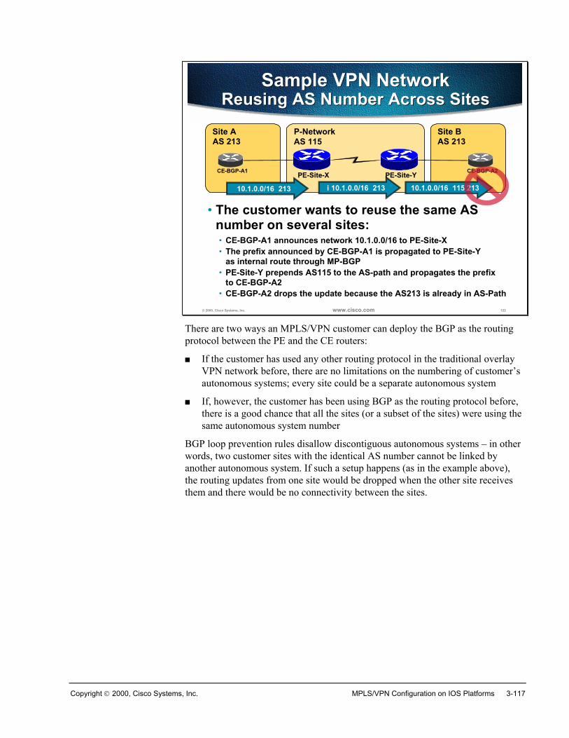
Copyright 2000, Cisco Systems, Inc. MPLS/VPN Configuration on IOS Platforms 3-117
© 2000, Cisco Systems, Inc. www.cisco.com 122
Sample VPN NetworkReusing AS Number Across Sites
Sample VPN NetworkReusing AS Number Across Sites
• The customer wants to reuse the same ASnumber on several sites:
Site BAS 213
Site AAS 213
P-NetworkAS 115
CE-BGP-A1 PE-Site-X PE-Site-Y CE-BGP-A2
10.1.0.0/16 213
• CE-BGP-A1 announces network 10.1.0.0/16 to PE-Site-X
i 10.1.0.0/16 213
• The prefix announced by CE-BGP-A1 is propagated to PE-Site-Yas internal route through MP-BGP
10.1.0.0/16 115 213
• PE-Site-Y prepends AS115 to the AS-path and propagates the prefixto CE-BGP-A2
• CE-BGP-A2 drops the update because the AS213 is already in AS-Path
There are two ways an MPLS/VPN customer can deploy the BGP as the routingprotocol between the PE and the CE routers:
� If the customer has used any other routing protocol in the traditional overlayVPN network before, there are no limitations on the numbering of customer’sautonomous systems; every site could be a separate autonomous system
� If, however, the customer has been using BGP as the routing protocol before,there is a good chance that all the sites (or a subset of the sites) were using thesame autonomous system number
BGP loop prevention rules disallow discontiguous autonomous systems – in otherwords, two customer sites with the identical AS number cannot be linked byanother autonomous system. If such a setup happens (as in the example above),the routing updates from one site would be dropped when the other site receivesthem and there would be no connectivity between the sites.
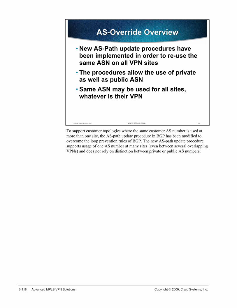
3-118 Advanced MPLS VPN Solutions Copyright 2000, Cisco Systems, Inc.
© 2000, Cisco Systems, Inc. www.cisco.com 123
AS-Override OverviewAS-Override Overview
• New AS-Path update procedures havebeen implemented in order to re-use thesame ASN on all VPN sites
• The procedures allow the use of privateas well as public ASN
• Same ASN may be used for all sites,whatever is their VPN
To support customer topologies where the same customer AS number is used atmore than one site, the AS-path update procedure in BGP has been modified toovercome the loop prevention rules of BGP. The new AS-path update proceduresupports usage of one AS number at many sites (even between several overlappingVPNs) and does not rely on distinction between private or public AS numbers.
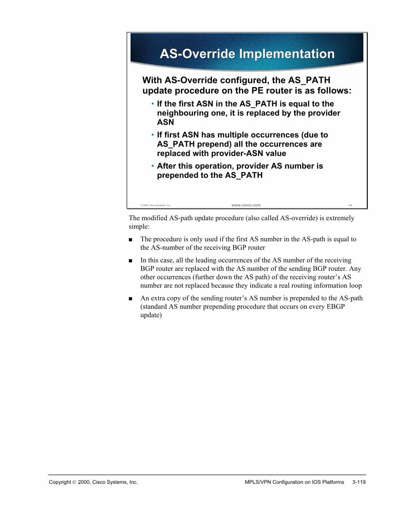
Copyright 2000, Cisco Systems, Inc. MPLS/VPN Configuration on IOS Platforms 3-119
© 2000, Cisco Systems, Inc. www.cisco.com 124
AS-Override ImplementationAS-Override Implementation
With AS-Override configured, the AS_PATHupdate procedure on the PE router is as follows:
• If the first ASN in the AS_PATH is equal to theneighbouring one, it is replaced by the providerASN
• If first ASN has multiple occurrences (due toAS_PATH prepend) all the occurrences arereplaced with provider-ASN value
• After this operation, provider AS number isprepended to the AS_PATH
The modified AS-path update procedure (also called AS-override) is extremelysimple:
� The procedure is only used if the first AS number in the AS-path is equal tothe AS-number of the receiving BGP router
� In this case, all the leading occurrences of the AS number of the receivingBGP router are replaced with the AS number of the sending BGP router. Anyother occurrences (further down the AS path) of the receiving router’s ASnumber are not replaced because they indicate a real routing information loop
� An extra copy of the sending router’s AS number is prepended to the AS-path(standard AS number prepending procedure that occurs on every EBGPupdate)
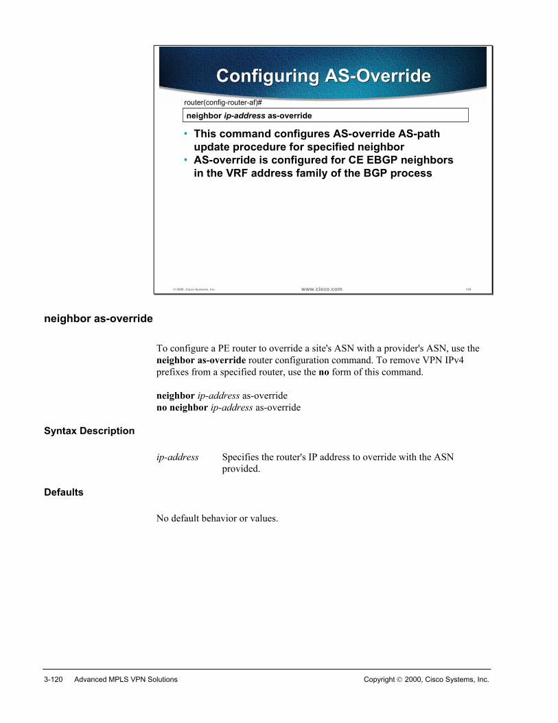
3-120 Advanced MPLS VPN Solutions Copyright 2000, Cisco Systems, Inc.
© 2000, Cisco Systems, Inc. www.cisco.com 125
neighbor ip-address as-overriderouter(config-router-af)#
• This command configures AS-override AS-pathupdate procedure for specified neighbor
• AS-override is configured for CE EBGP neighborsin the VRF address family of the BGP process
Configuring AS-OverrideConfiguring AS-Override
neighbor as-override
To configure a PE router to override a site's ASN with a provider's ASN, use theneighbor as-override router configuration command. To remove VPN IPv4prefixes from a specified router, use the no form of this command.
neighbor ip-address as-overrideno neighbor ip-address as-override
Syntax Description
ip-address Specifies the router's IP address to override with the ASNprovided.
Defaults
No default behavior or values.
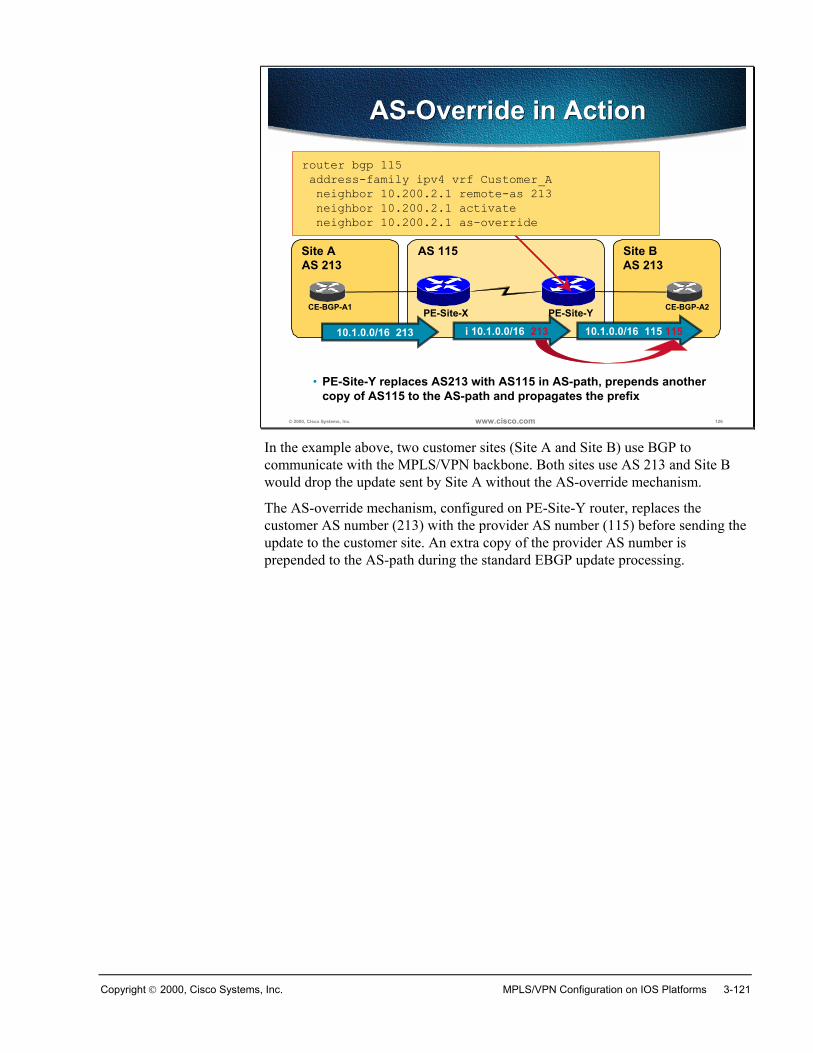
Copyright 2000, Cisco Systems, Inc. MPLS/VPN Configuration on IOS Platforms 3-121
© 2000, Cisco Systems, Inc. www.cisco.com 126
AS-Override in ActionAS-Override in Action
Site BAS 213
Site AAS 213
AS 115
CE-BGP-A1 PE-Site-X PE-Site-Y CE-BGP-A2
10.1.0.0/16 213 i 10.1.0.0/16 213 10.1.0.0/16 115 115
• PE-Site-Y replaces AS213 with AS115 in AS-path, prepends another copy of AS115 to the AS-path and propagates the prefix
router bgp 115 address-family ipv4 vrf Customer_A neighbor 10.200.2.1 remote-as 213 neighbor 10.200.2.1 activate neighbor 10.200.2.1 as-override
In the example above, two customer sites (Site A and Site B) use BGP tocommunicate with the MPLS/VPN backbone. Both sites use AS 213 and Site Bwould drop the update sent by Site A without the AS-override mechanism.
The AS-override mechanism, configured on PE-Site-Y router, replaces thecustomer AS number (213) with the provider AS number (115) before sending theupdate to the customer site. An extra copy of the provider AS number isprepended to the AS-path during the standard EBGP update processing.
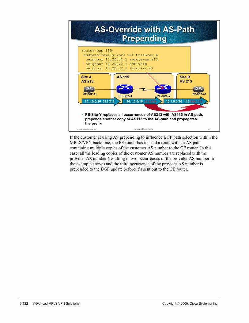
3-122 Advanced MPLS VPN Solutions Copyright 2000, Cisco Systems, Inc.
© 2000, Cisco Systems, Inc. www.cisco.com 127
AS-Override with AS-PathPrepending
AS-Override with AS-PathPrepending
Site BAS 213
Site AAS 213
AS 115
CE-BGP-A1 PE-Site-X PE-Site-Y CE-BGP-A2
10.1.0.0/16 213 213 i 10.1.0.0/16 213 213 10.1.0.0/16 115 115 115
• PE-Site-Y replaces all occurrences of AS213 with AS115 in AS-path, prepends another copy of AS115 to the AS-path and propagates the prefix
router bgp 115 address-family ipv4 vrf Customer_A neighbor 10.200.2.1 remote-as 213 neighbor 10.200.2.1 activate neighbor 10.200.2.1 as-override
If the customer is using AS prepending to influence BGP path selection within theMPLS/VPN backbone, the PE router has to send a route with an AS pathcontaining multiple copies of the customer AS number to the CE router. In thiscase, all the leading copies of the customer AS number are replaced with theprovider AS number (resulting in two occurrences of the provider AS number inthe example above) and the third occurrence of the provider AS number isprepended to the BGP update before it’s sent out to the CE router.
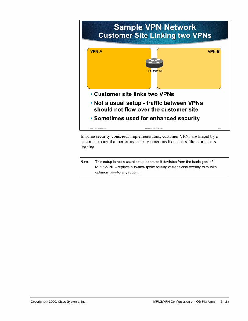
Copyright 2000, Cisco Systems, Inc. MPLS/VPN Configuration on IOS Platforms 3-123
© 2000, Cisco Systems, Inc. www.cisco.com 128
Sample VPN NetworkCustomer Site Linking two VPNs
Sample VPN NetworkCustomer Site Linking two VPNs
• Customer site links two VPNs• Not a usual setup - traffic between VPNs
should not flow over the customer site• Sometimes used for enhanced security
VPN-BVPN-A
CE-BGP-A1
In some security-conscious implementations, customer VPNs are linked by acustomer router that performs security functions like access filters or accesslogging.
Note This setup is not a usual setup because it deviates from the basic goal ofMPLS/VPN – replace hub-and-spoke routing of traditional overlay VPN withoptimum any-to-any routing.
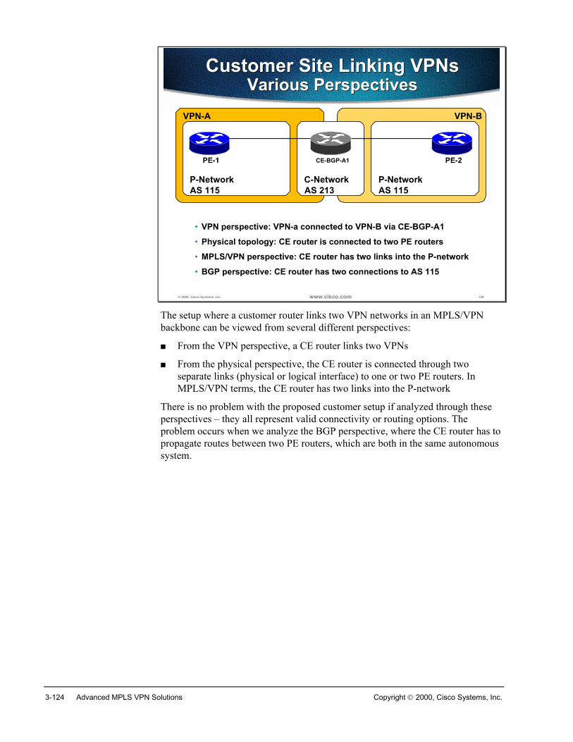
3-124 Advanced MPLS VPN Solutions Copyright 2000, Cisco Systems, Inc.
© 2000, Cisco Systems, Inc. www.cisco.com 129
Customer Site Linking VPNsVarious Perspectives
Customer Site Linking VPNsVarious Perspectives
• VPN perspective: VPN-a connected to VPN-B via CE-BGP-A1
VPN-BVPN-A
• MPLS/VPN perspective: CE router has two links into the P-network
C-Network P-NetworkP-Network
• Physical topology: CE router is connected to two PE routers
PE-1 PE-2CE-BGP-A1
• BGP perspective: CE router has two connections to AS 115
AS 115 AS 213 AS 115
The setup where a customer router links two VPN networks in an MPLS/VPNbackbone can be viewed from several different perspectives:
� From the VPN perspective, a CE router links two VPNs
� From the physical perspective, the CE router is connected through twoseparate links (physical or logical interface) to one or two PE routers. InMPLS/VPN terms, the CE router has two links into the P-network
There is no problem with the proposed customer setup if analyzed through theseperspectives – they all represent valid connectivity or routing options. Theproblem occurs when we analyze the BGP perspective, where the CE router has topropagate routes between two PE routers, which are both in the same autonomoussystem.
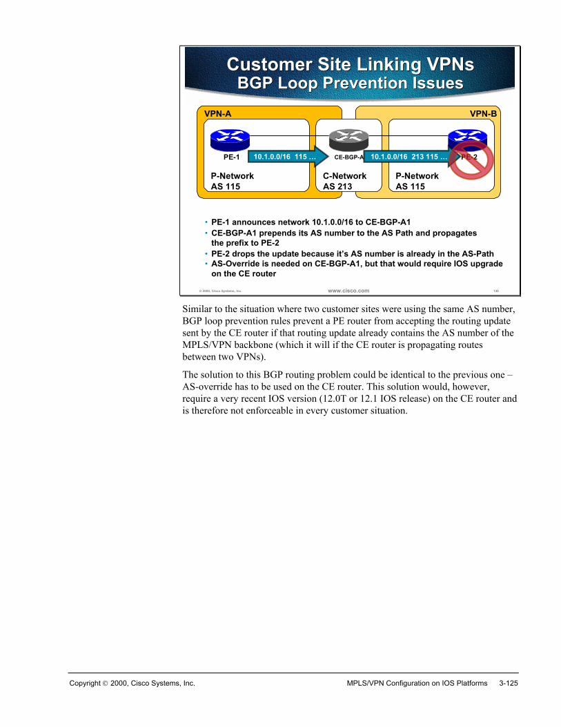
Copyright 2000, Cisco Systems, Inc. MPLS/VPN Configuration on IOS Platforms 3-125
© 2000, Cisco Systems, Inc. www.cisco.com 130
Customer Site Linking VPNsBGP Loop Prevention Issues
Customer Site Linking VPNsBGP Loop Prevention Issues
VPN-BVPN-A
C-Network P-NetworkP-Network
PE-1 PE-2CE-BGP-A1
AS 115 AS 213 AS 115
• PE-1 announces network 10.1.0.0/16 to CE-BGP-A1
10.1.0.0/16 115 …
• CE-BGP-A1 prepends its AS number to the AS Path and propagatesthe prefix to PE-2
10.1.0.0/16 213 115 …
• PE-2 drops the update because it’s AS number is already in the AS-Path• AS-Override is needed on CE-BGP-A1, but that would require IOS upgrade
on the CE router
Similar to the situation where two customer sites were using the same AS number,BGP loop prevention rules prevent a PE router from accepting the routing updatesent by the CE router if that routing update already contains the AS number of theMPLS/VPN backbone (which it will if the CE router is propagating routesbetween two VPNs).
The solution to this BGP routing problem could be identical to the previous one –AS-override has to be used on the CE router. This solution would, however,require a very recent IOS version (12.0T or 12.1 IOS release) on the CE router andis therefore not enforceable in every customer situation.
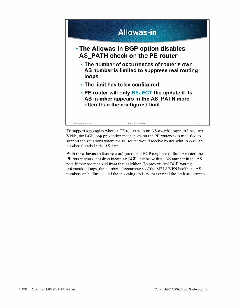
3-126 Advanced MPLS VPN Solutions Copyright 2000, Cisco Systems, Inc.
© 2000, Cisco Systems, Inc. www.cisco.com 131
Allowas-inAllowas-in
• The Allowas-in BGP option disablesAS_PATH check on the PE router• The number of occurrences of router’s own
AS number is limited to suppress real routingloops
• The limit has to be configured• PE router will only REJECT the update if its
AS number appears in the AS_PATH moreoften than the configured limit
To support topologies where a CE router with no AS-override support links twoVPNs, the BGP loop prevention mechanism on the PE routers was modified tosupport the situations where the PE router would receive routes with its own ASnumber already in the AS path.
With the allowas-in feature configured on a BGP neighbor of the PE router, thePE router would not drop incoming BGP updates with its AS number in the ASpath if they are received from that neighbor. To prevent real BGP routinginformation loops, the number of occurrences of the MPLS/VPN backbone ASnumber can be limited and the incoming updates that exceed the limit are dropped.
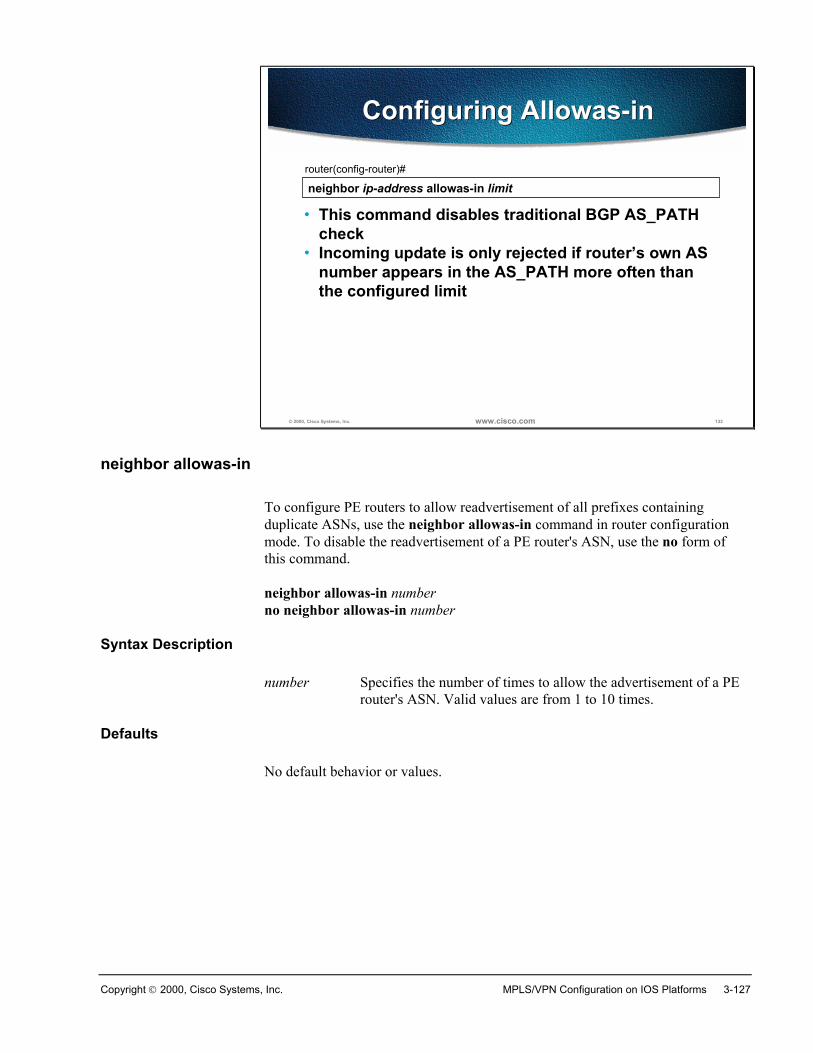
Copyright 2000, Cisco Systems, Inc. MPLS/VPN Configuration on IOS Platforms 3-127
© 2000, Cisco Systems, Inc. www.cisco.com 132
neighbor ip-address allowas-in limitrouter(config-router)#
• This command disables traditional BGP AS_PATHcheck
• Incoming update is only rejected if router’s own ASnumber appears in the AS_PATH more often thanthe configured limit
Configuring Allowas-inConfiguring Allowas-in
neighbor allowas-in
To configure PE routers to allow readvertisement of all prefixes containingduplicate ASNs, use the neighbor allowas-in command in router configurationmode. To disable the readvertisement of a PE router's ASN, use the no form ofthis command.
neighbor allowas-in numberno neighbor allowas-in number
Syntax Description
number Specifies the number of times to allow the advertisement of a PErouter's ASN. Valid values are from 1 to 10 times.
Defaults
No default behavior or values.
3-128 Advanced MPLS VPN Solutions Copyright 2000, Cisco Systems, Inc.
© 2000, Cisco Systems, Inc. www.cisco.com 133
Additional BGP LoopPrevention Mechanisms
Additional BGP LoopPrevention Mechanisms
• AS-Path based BGP loop prevention isbypassed with AS-Override and Allowas-In features
• Site of Origin (extended BGPcommunity) can be used to preventloops in these scenarios• Site of Origin (SOO) is only needed for
multihomed sites• SOO is not needed for stub sites
Most aspects of BGP loop prevention are bypassed when you’re using either as-override or allowas-in features. Although the routing information loops can stillbe detected by counting occurrences of an autonomous system number in the ASpath in end-to-end BGP routing scenario, the situation can get worse when BGP ismixed with other PE-CE routing protocols. The Site-of-origin extended BGPcommunity can be used as an additional loop prevention mechanism in thesescenarios.
Note Site-of-origin and any other loop prevention mechanisms are only needed forcustomer networks with multi-homed sites. Loops can never occur in customernetworks that only have stub sites.
Copyright 2000, Cisco Systems, Inc. MPLS/VPN Configuration on IOS Platforms 3-129
© 2000, Cisco Systems, Inc. www.cisco.com 134
Setting Site of OriginSetting Site of Origin
• When running EBGP between PE andCE, SOO is configured through a route-map command
• For other routing protocols, SOO can beapplied to routes learned through aparticular VRF interface during theredistribution into BGP
There are two ways to set site-of-origin attribute on a BGP route:
� For routes received from the BGP-speaking CE routers, the site-of-origin is setby incoming route map on the PE-router
� For all other routes, a route-map setting site-of-origin is applied to theincoming interface and the site-of-origin as set by the route-map is attached tothe BGP route when an IGP route received through that interface isredistributed into BGP.
3-130 Advanced MPLS VPN Solutions Copyright 2000, Cisco Systems, Inc.
© 2000, Cisco Systems, Inc. www.cisco.com 135
Filters based on SOOFilters based on SOO
• Route-maps are used on EBGP PE-CEconnections to filter on SOO values
• For other routing protocols, routesredistributed from BGP are filteredbased on Site of Origin valuesconfigured on outgoing interfaces
Outgoing filters based on site-of-origin attribute also depend on the routingprotocol used:
� For situations where BGP is used as the PE-CE routing protocol, outboundroute maps can be used on the PE router to deny routes matching particularvalue of site-of-origin
� For all other routing protocols, filtering is performed based on site-of-originroute-map configured on the outgoing interface before the update is sentacross that interface to the CE router
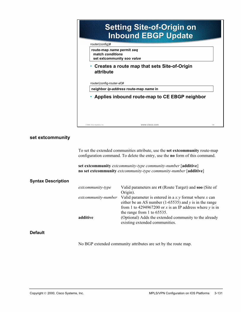
Copyright 2000, Cisco Systems, Inc. MPLS/VPN Configuration on IOS Platforms 3-131
© 2000, Cisco Systems, Inc. www.cisco.com 136
route-map name permit seq match conditions set extcommunity soo value
router(config)#
• Creates a route map that sets Site-of-Originattribute
Setting Site-of-Origin onInbound EBGP Update
Setting Site-of-Origin onInbound EBGP Update
neighbor ip-address route-map name inrouter(config-router-af)#
• Applies inbound route-map to CE EBGP neighbor
set extcommunity
To set the extended communities attribute, use the set extcommunity route-mapconfiguration command. To delete the entry, use the no form of this command.
set extcommunity extcommunity-type community-number [additive]no set extcommunity extcommunity-type community-number [additive]
Syntax Descriptionextcommunity-type Valid parameters are rt (Route Target) and soo (Site of
Origin). extcommunity-number Valid parameter is entered in a x:y format where x can
either be an AS number (1-65535) and y is in the rangefrom 1 to 4294967200 or x is an IP address where y is inthe range from 1 to 65535.
additive (Optional) Adds the extended community to the alreadyexisting extended communities.
Default
No BGP extended community attributes are set by the route map.
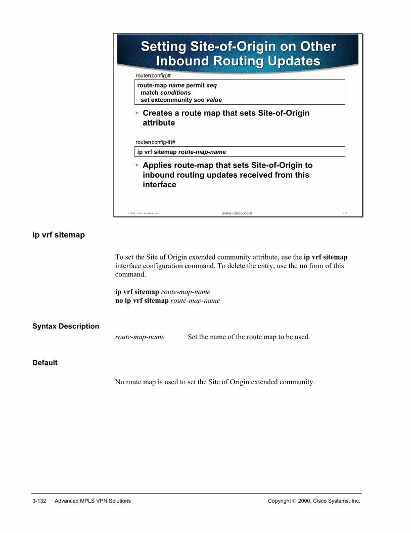
3-132 Advanced MPLS VPN Solutions Copyright 2000, Cisco Systems, Inc.
© 2000, Cisco Systems, Inc. www.cisco.com 137
Setting Site-of-Origin on OtherInbound Routing Updates
Setting Site-of-Origin on OtherInbound Routing Updates
route-map name permit seq match conditions set extcommunity soo value
router(config)#
• Creates a route map that sets Site-of-Originattribute
ip vrf sitemap route-map-namerouter(config-if)#
• Applies route-map that sets Site-of-Origin toinbound routing updates received from thisinterface
ip vrf sitemap
To set the Site of Origin extended community attribute, use the ip vrf sitemapinterface configuration command. To delete the entry, use the no form of thiscommand.
ip vrf sitemap route-map-nameno ip vrf sitemap route-map-name
Syntax Descriptionroute-map-name Set the name of the route map to be used.
Default
No route map is used to set the Site of Origin extended community.
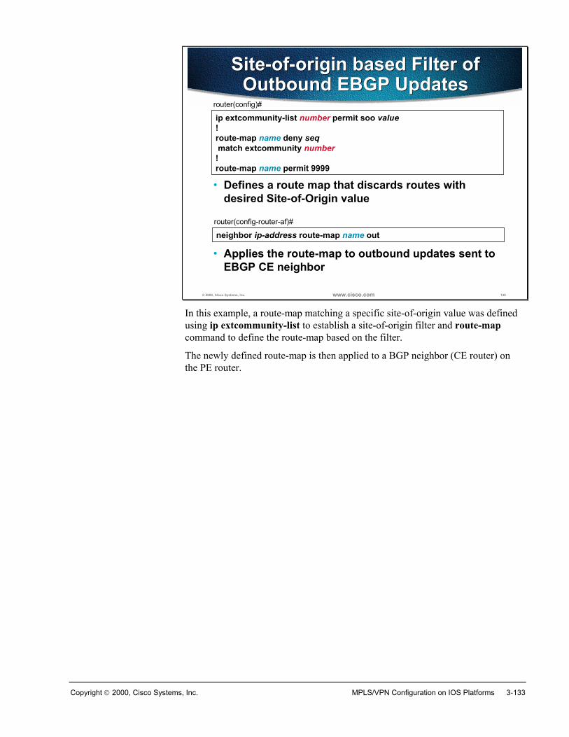
Copyright 2000, Cisco Systems, Inc. MPLS/VPN Configuration on IOS Platforms 3-133
© 2000, Cisco Systems, Inc. www.cisco.com 138
ip extcommunity-list number permit soo value!route-map name deny seq match extcommunity number!route-map name permit 9999
router(config)#
• Defines a route map that discards routes withdesired Site-of-Origin value
Site-of-origin based Filter ofOutbound EBGP Updates
Site-of-origin based Filter ofOutbound EBGP Updates
neighbor ip-address route-map name outrouter(config-router-af)#
• Applies the route-map to outbound updates sent toEBGP CE neighbor
In this example, a route-map matching a specific site-of-origin value was definedusing ip extcommunity-list to establish a site-of-origin filter and route-mapcommand to define the route-map based on the filter.
The newly defined route-map is then applied to a BGP neighbor (CE router) onthe PE router.
3-134 Advanced MPLS VPN Solutions Copyright 2000, Cisco Systems, Inc.
SummaryExternal BGP can be used with the CE routers to exchange routing information.
If the CE sites are all using the same AS number, the information coming fromone site is regarded as a routing loop on other sites. AS-Override feature should beenabled on all neighborships with the CE routers to overcome this problem.
If there is a multihomed site that needs to be able to re-announce the informationback into the core (Hub-and-Spoke design), the PE routers will regard this as arouting loop. Allowas-in feature should be used to overcome this problem. Thismay, however, cause routing loops and an additional extended community Site ofOrigin can be used to prevent them.
Review Questions� When would you need the AS-override feature?
� How does the AS-override feature work?
� When would you need the Allowas-In feature?
� Why can’t you use the AS-override feature instead of the Allowas-In feature?
� How do you prevent BGP loops when using AS-override?
� How do you prevent BGP loops when using Allowas-in?
� When would you have to use Site-of-Origin?
� What is Site-of-Origin?
� Where can you set the Site-of-Origin?
� How do you implement filters based on Site-of-Origin?
4
Using OSPF inan MPLS VPNEnvironment
OverviewThis chapter introduces the interaction between multi-protocol Border GatewayProtocol (MP-BGP) running between Provider Edge routers (PE-routers) andOpen Shortest Path First (OSPF) protocol running inside a Virtual PrivateNetwork (VPN) implemented with MPLS VPN technology.
ObjectivesUpon completion of this chapter, you will be able to perform the following tasks:
� Describe OSPF operation inside a VPN
� Describe enhanced OSPF hierarchical model
� Describe the interactions between OSPF and MP-BGP
� Use OSPF as the PE-CE routing protocol in a complex MPLS VPNenvironment
4-2 Advanced MPLS VPN Solutions Copyright 2000, Cisco Systems, Inc.
Using OSPF as the PE-CE Protocol in an MPLSVPN Environment
ObjectivesUpon completion of this section, you will be able to perform the following tasks:
� Describe the enhanced OSPF hierarchical model
� Describe the propagation of OSPF customer routes across the MPLS VPNbackbone
� Explain why the OSPF routes propagated through MP-BGP are not reinsertedinto OSPF as external (LSA type-5) routes
� Describe the route selection process in PE routers
� Explain loop prevention mechanisms
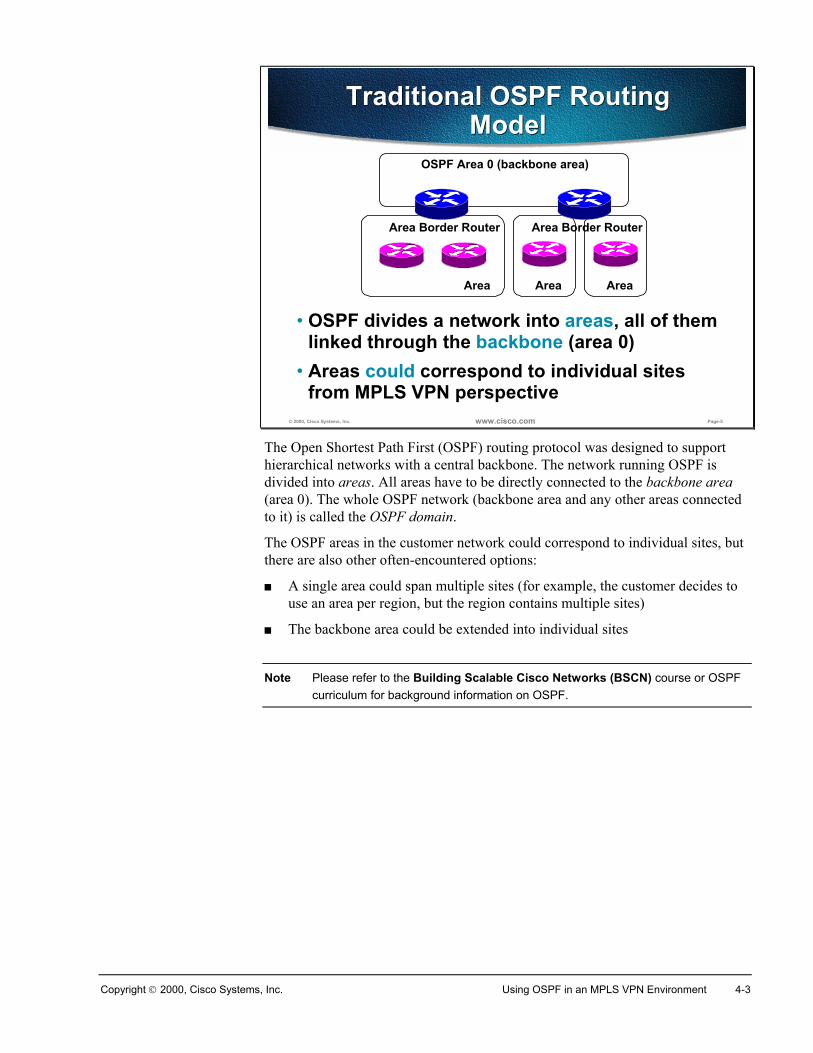
Copyright 2000, Cisco Systems, Inc. Using OSPF in an MPLS VPN Environment 4-3
© 2000, Cisco Systems, Inc. www.cisco.com Page-5
Traditional OSPF RoutingModel
Traditional OSPF RoutingModel
• OSPF divides a network into areas, all of themlinked through the backbone (area 0)
• Areas could correspond to individual sitesfrom MPLS VPN perspective
Area
OSPF Area 0 (backbone area)
Area Border Router
Area Area
Area Border Router
The Open Shortest Path First (OSPF) routing protocol was designed to supporthierarchical networks with a central backbone. The network running OSPF isdivided into areas. All areas have to be directly connected to the backbone area(area 0). The whole OSPF network (backbone area and any other areas connectedto it) is called the OSPF domain.
The OSPF areas in the customer network could correspond to individual sites, butthere are also other often-encountered options:
� A single area could span multiple sites (for example, the customer decides touse an area per region, but the region contains multiple sites)
� The backbone area could be extended into individual sites
Note Please refer to the Building Scalable Cisco Networks (BSCN) course or OSPFcurriculum for background information on OSPF.
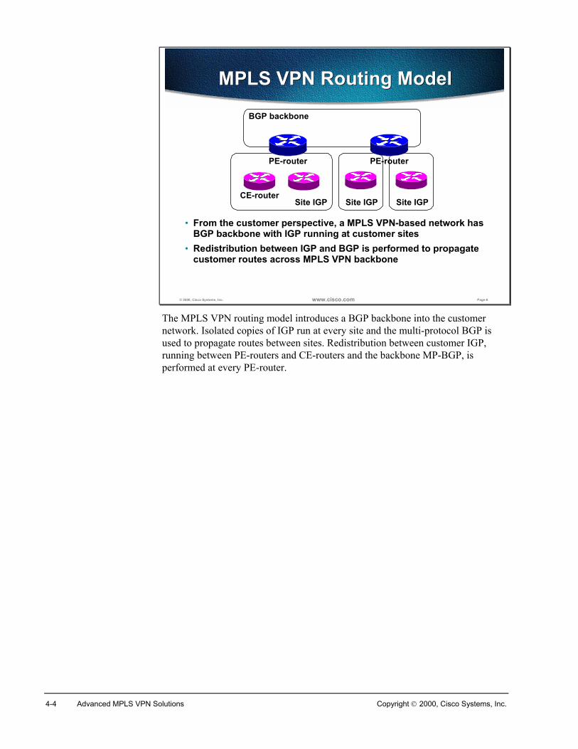
4-4 Advanced MPLS VPN Solutions Copyright 2000, Cisco Systems, Inc.
© 2000, Cisco Systems, Inc. www.cisco.com Page-6
MPLS VPN Routing ModelMPLS VPN Routing Model
• From the customer perspective, a MPLS VPN-based network hasBGP backbone with IGP running at customer sites
• Redistribution between IGP and BGP is performed to propagatecustomer routes across MPLS VPN backbone
Site IGP
BGP backbone
CE-router
PE-router
Site IGP Site IGP
PE-router
The MPLS VPN routing model introduces a BGP backbone into the customernetwork. Isolated copies of IGP run at every site and the multi-protocol BGP isused to propagate routes between sites. Redistribution between customer IGP,running between PE-routers and CE-routers and the backbone MP-BGP, isperformed at every PE-router.
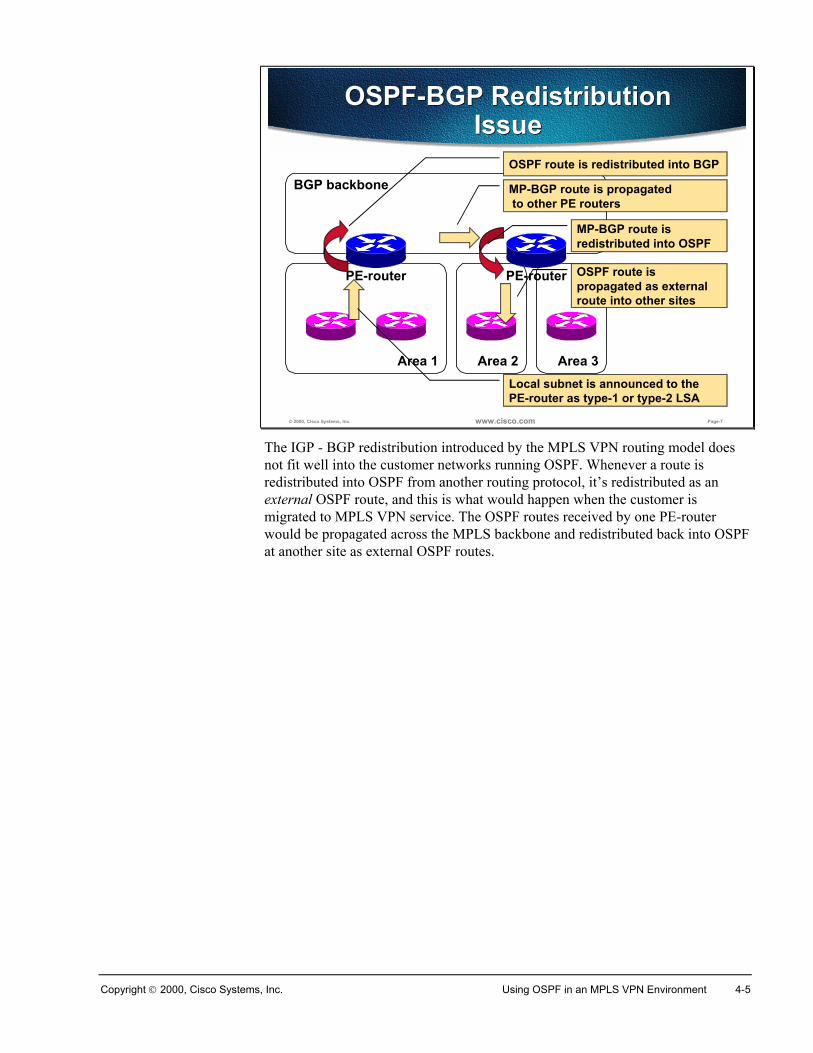
Copyright 2000, Cisco Systems, Inc. Using OSPF in an MPLS VPN Environment 4-5
© 2000, Cisco Systems, Inc. www.cisco.com Page-7
OSPF-BGP RedistributionIssue
OSPF-BGP RedistributionIssue
Area 1
BGP backbone
PE-router
Area 2 Area 3
PE-router
Local subnet is announced to thePE-router as type-1 or type-2 LSA
OSPF route is redistributed into BGP
MP-BGP route is propagated to other PE routers
MP-BGP route isredistributed into OSPF
OSPF route ispropagated as externalroute into other sites
The IGP - BGP redistribution introduced by the MPLS VPN routing model doesnot fit well into the customer networks running OSPF. Whenever a route isredistributed into OSPF from another routing protocol, it’s redistributed as anexternal OSPF route, and this is what would happen when the customer ismigrated to MPLS VPN service. The OSPF routes received by one PE-routerwould be propagated across the MPLS backbone and redistributed back into OSPFat another site as external OSPF routes.
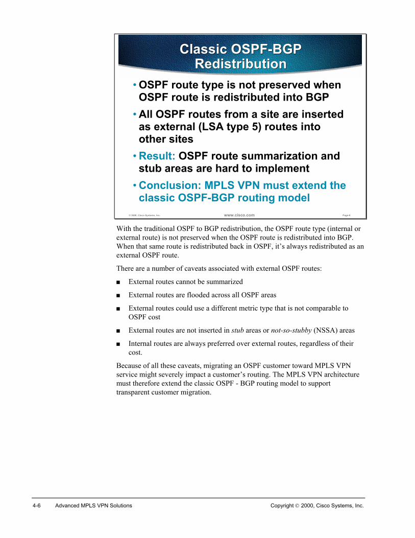
4-6 Advanced MPLS VPN Solutions Copyright 2000, Cisco Systems, Inc.
© 2000, Cisco Systems, Inc. www.cisco.com Page-8
Classic OSPF-BGPRedistribution
Classic OSPF-BGPRedistribution
• OSPF route type is not preserved whenOSPF route is redistributed into BGP
• All OSPF routes from a site are insertedas external (LSA type 5) routes intoother sites
• Result: OSPF route summarization andstub areas are hard to implement
• Conclusion: MPLS VPN must extend theclassic OSPF-BGP routing model
With the traditional OSPF to BGP redistribution, the OSPF route type (internal orexternal route) is not preserved when the OSPF route is redistributed into BGP.When that same route is redistributed back in OSPF, it’s always redistributed as anexternal OSPF route.
There are a number of caveats associated with external OSPF routes:
� External routes cannot be summarized
� External routes are flooded across all OSPF areas
� External routes could use a different metric type that is not comparable toOSPF cost
� External routes are not inserted in stub areas or not-so-stubby (NSSA) areas
� Internal routes are always preferred over external routes, regardless of theircost.
Because of all these caveats, migrating an OSPF customer toward MPLS VPNservice might severely impact a customer’s routing. The MPLS VPN architecturemust therefore extend the classic OSPF - BGP routing model to supporttransparent customer migration.
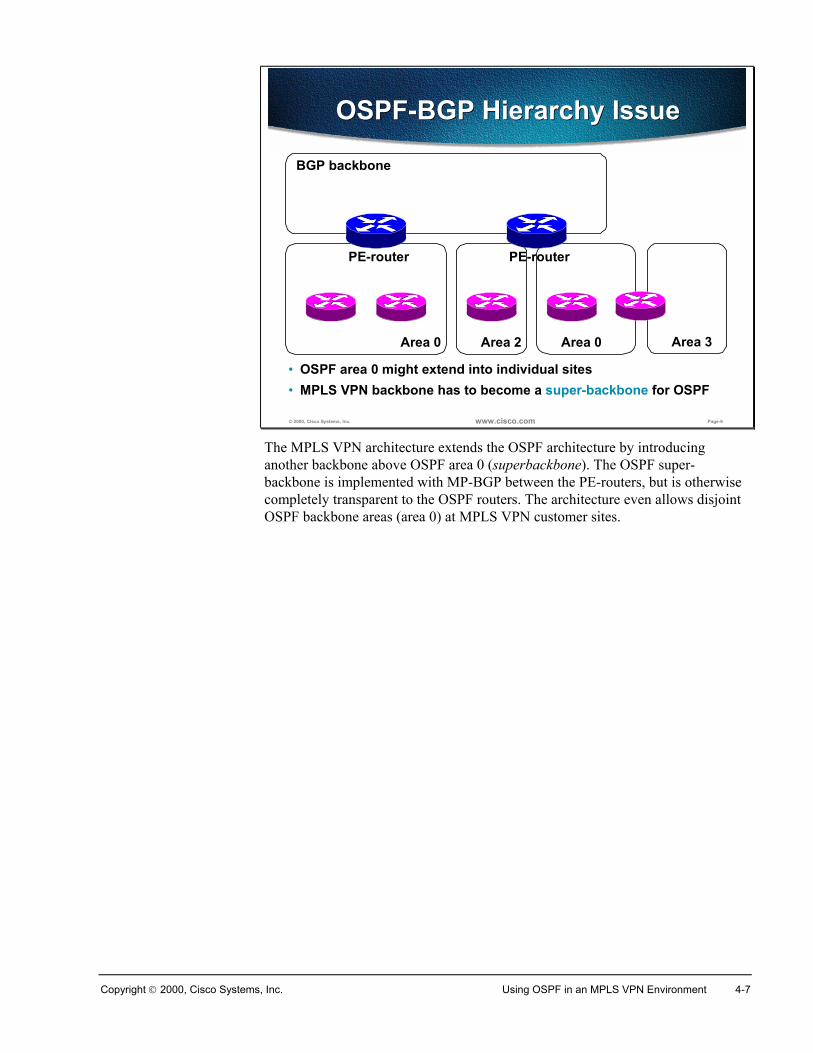
Copyright 2000, Cisco Systems, Inc. Using OSPF in an MPLS VPN Environment 4-7
© 2000, Cisco Systems, Inc. www.cisco.com Page-9
OSPF-BGP Hierarchy IssueOSPF-BGP Hierarchy Issue
Area 0
BGP backbone
PE-router
Area 0Area 2
PE-router
Area 3
• OSPF area 0 might extend into individual sites• MPLS VPN backbone has to become a super-backbone for OSPF
The MPLS VPN architecture extends the OSPF architecture by introducinganother backbone above OSPF area 0 (superbackbone). The OSPF super-backbone is implemented with MP-BGP between the PE-routers, but is otherwisecompletely transparent to the OSPF routers. The architecture even allows disjointOSPF backbone areas (area 0) at MPLS VPN customer sites.
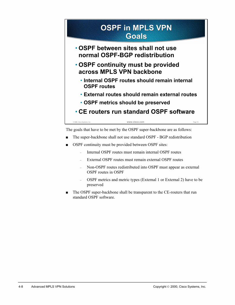
4-8 Advanced MPLS VPN Solutions Copyright 2000, Cisco Systems, Inc.
© 2000, Cisco Systems, Inc. www.cisco.com Page-10
OSPF in MPLS VPNGoals
OSPF in MPLS VPNGoals
• OSPF between sites shall not usenormal OSPF-BGP redistribution
• OSPF continuity must be providedacross MPLS VPN backbone• Internal OSPF routes should remain internal
OSPF routes• External routes should remain external routes• OSPF metrics should be preserved
• CE routers run standard OSPF software
The goals that have to be met by the OSPF super-backbone are as follows:
� The super-backbone shall not use standard OSPF - BGP redistribution
� OSPF continuity must be provided between OSPF sites:
– Internal OSPF routes must remain internal OSPF routes
– External OSPF routes must remain external OSPF routes
– Non-OSPF routes redistributed into OSPF must appear as externalOSPF routes in OSPF
– OSPF metrics and metric types (External 1 or External 2) have to bepreserved
� The OSPF super-backbone shall be transparent to the CE-routers that runstandard OSPF software.
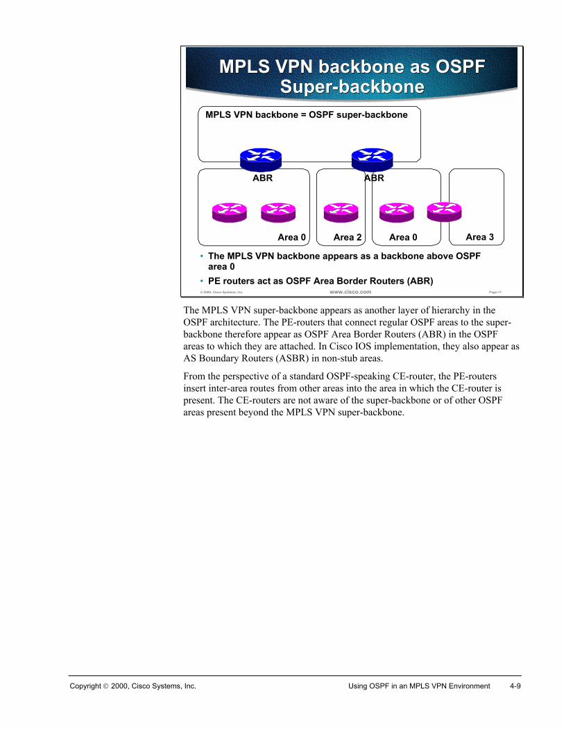
Copyright 2000, Cisco Systems, Inc. Using OSPF in an MPLS VPN Environment 4-9
© 2000, Cisco Systems, Inc. www.cisco.com Page-11
MPLS VPN backbone as OSPFSuper-backbone
MPLS VPN backbone as OSPFSuper-backbone
Area 0
MPLS VPN backbone = OSPF super-backbone
ABR
Area 0Area 2
ABR
Area 3
• The MPLS VPN backbone appears as a backbone above OSPFarea 0
• PE routers act as OSPF Area Border Routers (ABR)
The MPLS VPN super-backbone appears as another layer of hierarchy in theOSPF architecture. The PE-routers that connect regular OSPF areas to the super-backbone therefore appear as OSPF Area Border Routers (ABR) in the OSPFareas to which they are attached. In Cisco IOS implementation, they also appear asAS Boundary Routers (ASBR) in non-stub areas.
From the perspective of a standard OSPF-speaking CE-router, the PE-routersinsert inter-area routes from other areas into the area in which the CE-router ispresent. The CE-routers are not aware of the super-backbone or of other OSPFareas present beyond the MPLS VPN super-backbone.
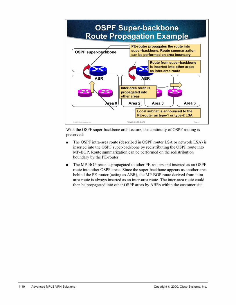
4-10 Advanced MPLS VPN Solutions Copyright 2000, Cisco Systems, Inc.
© 2000, Cisco Systems, Inc. www.cisco.com Page-12
OSPF Super-backboneRoute Propagation Example
OSPF Super-backboneRoute Propagation Example
Area 0
OSPF super-backbone
ABR
Area 0Area 2
ABR
Area 3
Local subnet is announced to thePE-router as type-1 or type-2 LSA
PE-router propagates the route intosuper-backbone. Route summarizationcan be performed on area boundary
Route from super-backboneis inserted into other areasas inter-area route
Inter-area route ispropagated intoother areas
With the OSPF super-backbone architecture, the continuity of OSPF routing ispreserved:
� The OSPF intra-area route (described in OSPF router LSA or network LSA) isinserted into the OSPF super-backbone by redistributing the OSPF route intoMP-BGP. Route summarization can be performed on the redistributionboundary by the PE-router.
� The MP-BGP route is propagated to other PE-routers and inserted as an OSPFroute into other OSPF areas. Since the super-backbone appears as another areabehind the PE-router (acting as ABR), the MP-BGP route derived from intra-area route is always inserted as an inter-area route. The inter-area route couldthen be propagated into other OSPF areas by ABRs within the customer site.
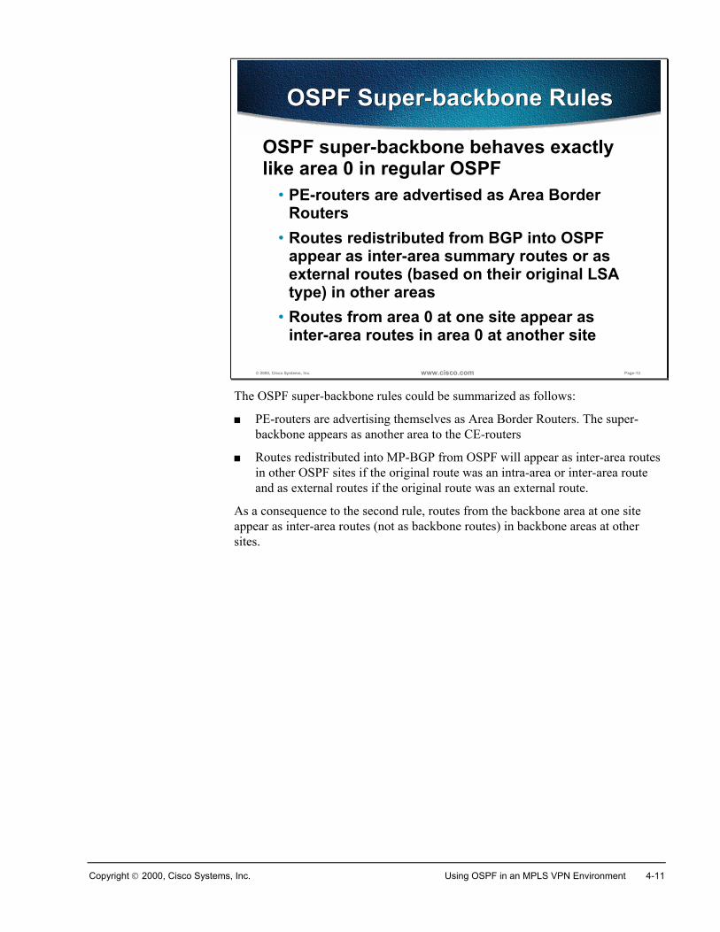
Copyright 2000, Cisco Systems, Inc. Using OSPF in an MPLS VPN Environment 4-11
© 2000, Cisco Systems, Inc. www.cisco.com Page-13
OSPF Super-backbone RulesOSPF Super-backbone Rules
OSPF super-backbone behaves exactlylike area 0 in regular OSPF
• PE-routers are advertised as Area BorderRouters
• Routes redistributed from BGP into OSPFappear as inter-area summary routes or asexternal routes (based on their original LSAtype) in other areas
• Routes from area 0 at one site appear asinter-area routes in area 0 at another site
The OSPF super-backbone rules could be summarized as follows:
� PE-routers are advertising themselves as Area Border Routers. The super-backbone appears as another area to the CE-routers
� Routes redistributed into MP-BGP from OSPF will appear as inter-area routesin other OSPF sites if the original route was an intra-area or inter-area routeand as external routes if the original route was an external route.
As a consequence to the second rule, routes from the backbone area at one siteappear as inter-area routes (not as backbone routes) in backbone areas at othersites.
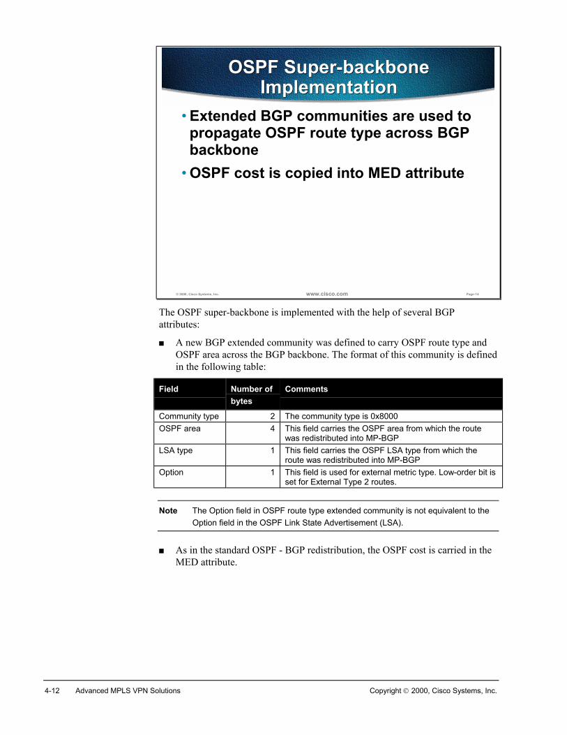
4-12 Advanced MPLS VPN Solutions Copyright 2000, Cisco Systems, Inc.
© 2000, Cisco Systems, Inc. www.cisco.com Page-14
OSPF Super-backboneImplementation
OSPF Super-backboneImplementation
• Extended BGP communities are used topropagate OSPF route type across BGPbackbone
• OSPF cost is copied into MED attribute
The OSPF super-backbone is implemented with the help of several BGPattributes:
� A new BGP extended community was defined to carry OSPF route type andOSPF area across the BGP backbone. The format of this community is definedin the following table:
Field Number ofbytes
Comments
Community type 2 The community type is 0x8000OSPF area 4 This field carries the OSPF area from which the route
was redistributed into MP-BGPLSA type 1 This field carries the OSPF LSA type from which the
route was redistributed into MP-BGPOption 1 This field is used for external metric type. Low-order bit is
set for External Type 2 routes.
Note The Option field in OSPF route type extended community is not equivalent to theOption field in the OSPF Link State Advertisement (LSA).
� As in the standard OSPF - BGP redistribution, the OSPF cost is carried in theMED attribute.
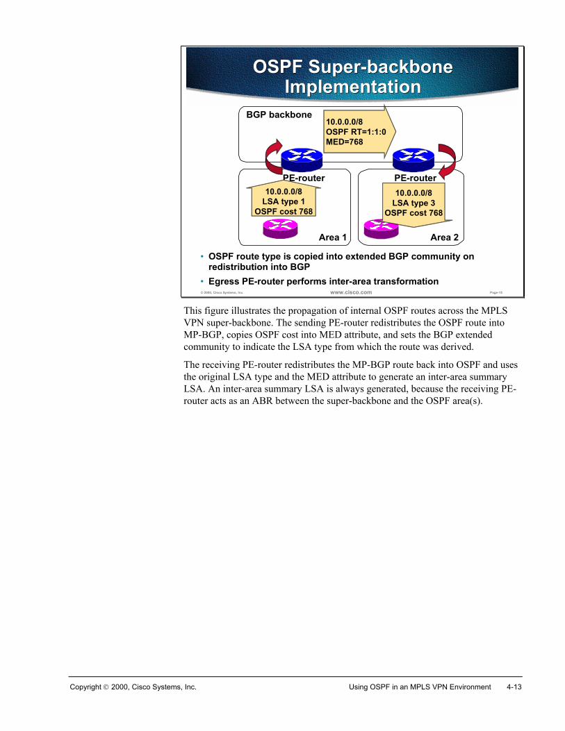
Copyright 2000, Cisco Systems, Inc. Using OSPF in an MPLS VPN Environment 4-13
© 2000, Cisco Systems, Inc. www.cisco.com Page-15
OSPF Super-backboneImplementation
OSPF Super-backboneImplementation
Area 1
BGP backbone
PE-router
Area 2
PE-router10.0.0.0/8
LSA type 1OSPF cost 768
10.0.0.0/8OSPF RT=1:1:0MED=768
10.0.0.0/8LSA type 3
OSPF cost 768
• OSPF route type is copied into extended BGP community onredistribution into BGP
• Egress PE-router performs inter-area transformation
This figure illustrates the propagation of internal OSPF routes across the MPLSVPN super-backbone. The sending PE-router redistributes the OSPF route intoMP-BGP, copies OSPF cost into MED attribute, and sets the BGP extendedcommunity to indicate the LSA type from which the route was derived.
The receiving PE-router redistributes the MP-BGP route back into OSPF and usesthe original LSA type and the MED attribute to generate an inter-area summaryLSA. An inter-area summary LSA is always generated, because the receiving PE-router acts as an ABR between the super-backbone and the OSPF area(s).
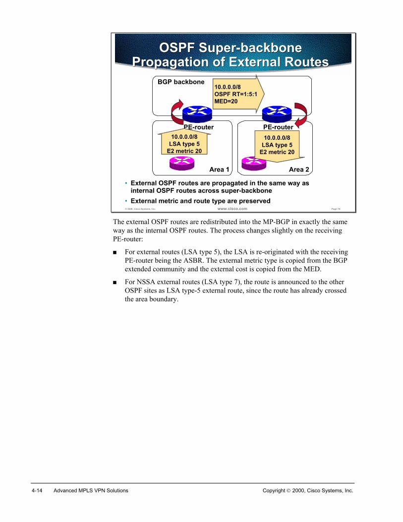
4-14 Advanced MPLS VPN Solutions Copyright 2000, Cisco Systems, Inc.
© 2000, Cisco Systems, Inc. www.cisco.com Page-16
OSPF Super-backbonePropagation of External Routes
OSPF Super-backbonePropagation of External Routes
Area 1
BGP backbone
PE-router
Area 2
PE-router10.0.0.0/8
LSA type 5E2 metric 20
10.0.0.0/8OSPF RT=1:5:1MED=20
10.0.0.0/8LSA type 5
E2 metric 20
• External OSPF routes are propagated in the same way asinternal OSPF routes across super-backbone
• External metric and route type are preserved
The external OSPF routes are redistributed into the MP-BGP in exactly the sameway as the internal OSPF routes. The process changes slightly on the receivingPE-router:
� For external routes (LSA type 5), the LSA is re-originated with the receivingPE-router being the ASBR. The external metric type is copied from the BGPextended community and the external cost is copied from the MED.
� For NSSA external routes (LSA type 7), the route is announced to the otherOSPF sites as LSA type-5 external route, since the route has already crossedthe area boundary.
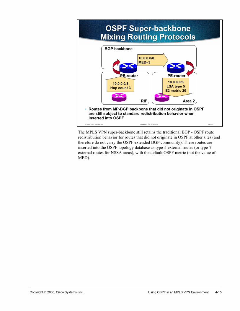
Copyright 2000, Cisco Systems, Inc. Using OSPF in an MPLS VPN Environment 4-15
© 2000, Cisco Systems, Inc. www.cisco.com Page-17
OSPF Super-backboneMixing Routing Protocols
OSPF Super-backboneMixing Routing Protocols
RIP
BGP backbone
PE-router
Area 2
PE-router
10.0.0.0/8Hop count 3
10.0.0.0/8MED=3
10.0.0.0/8LSA type 5
E2 metric 20
• Routes from MP-BGP backbone that did not originate in OSPFare still subject to standard redistribution behavior wheninserted into OSPF
The MPLS VPN super-backbone still retains the traditional BGP - OSPF routeredistribution behavior for routes that did not originate in OSPF at other sites (andtherefore do not carry the OSPF extended BGP community). These routes areinserted into the OSPF topology database as type-5 external routes (or type-7external routes for NSSA areas), with the default OSPF metric (not the value ofMED).
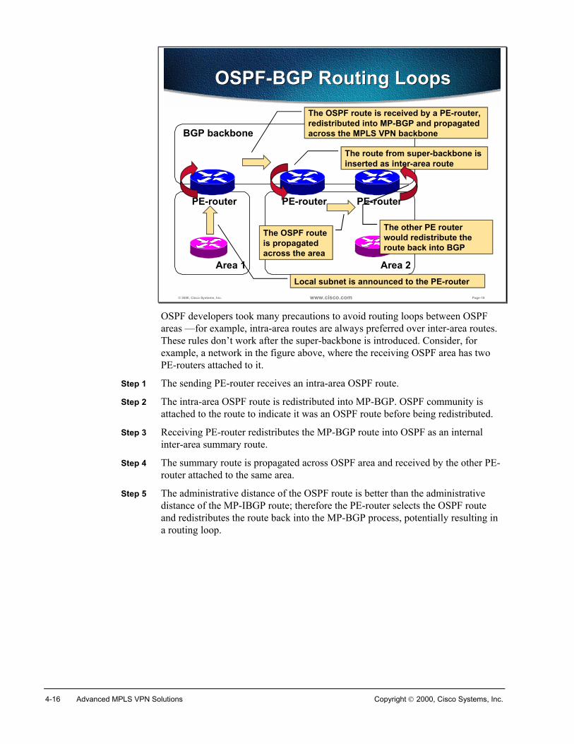
4-16 Advanced MPLS VPN Solutions Copyright 2000, Cisco Systems, Inc.
© 2000, Cisco Systems, Inc. www.cisco.com Page-18
OSPF-BGP Routing LoopsOSPF-BGP Routing Loops
Area 1
BGP backbone
PE-router
Area 2
PE-routerPE-router
Local subnet is announced to the PE-router
The route from super-backbone isinserted as inter-area route
The OSPF route is received by a PE-router,redistributed into MP-BGP and propagatedacross the MPLS VPN backbone
The other PE routerwould redistribute theroute back into BGP
The OSPF routeis propagatedacross the area
OSPF developers took many precautions to avoid routing loops between OSPFareas —for example, intra-area routes are always preferred over inter-area routes.These rules don’t work after the super-backbone is introduced. Consider, forexample, a network in the figure above, where the receiving OSPF area has twoPE-routers attached to it.
Step 1 The sending PE-router receives an intra-area OSPF route.
Step 2 The intra-area OSPF route is redistributed into MP-BGP. OSPF community isattached to the route to indicate it was an OSPF route before being redistributed.
Step 3 Receiving PE-router redistributes the MP-BGP route into OSPF as an internalinter-area summary route.
Step 4 The summary route is propagated across OSPF area and received by the other PE-router attached to the same area.
Step 5 The administrative distance of the OSPF route is better than the administrativedistance of the MP-IBGP route; therefore the PE-router selects the OSPF routeand redistributes the route back into the MP-BGP process, potentially resulting ina routing loop.
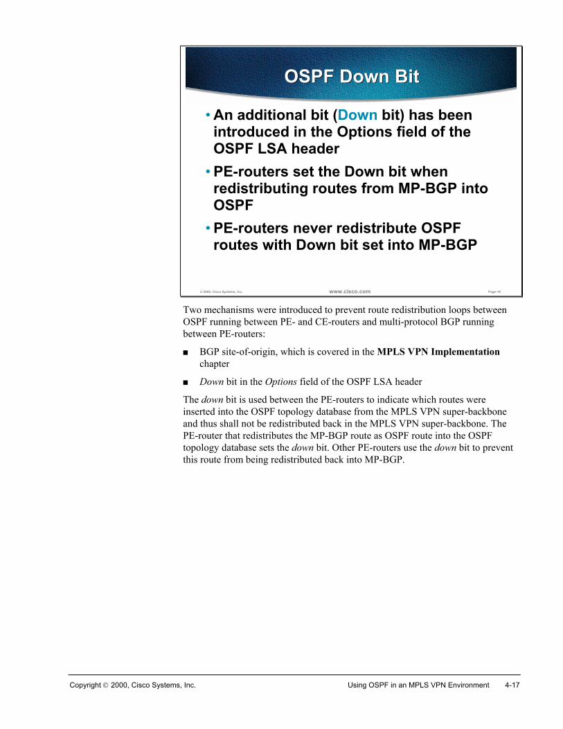
Copyright 2000, Cisco Systems, Inc. Using OSPF in an MPLS VPN Environment 4-17
© 2000, Cisco Systems, Inc. www.cisco.com Page-19
OSPF Down BitOSPF Down Bit
• An additional bit (Down bit) has beenintroduced in the Options field of theOSPF LSA header
• PE-routers set the Down bit whenredistributing routes from MP-BGP intoOSPF
• PE-routers never redistribute OSPFroutes with Down bit set into MP-BGP
Two mechanisms were introduced to prevent route redistribution loops betweenOSPF running between PE- and CE-routers and multi-protocol BGP runningbetween PE-routers:
� BGP site-of-origin, which is covered in the MPLS VPN Implementationchapter
� Down bit in the Options field of the OSPF LSA header
The down bit is used between the PE-routers to indicate which routes wereinserted into the OSPF topology database from the MPLS VPN super-backboneand thus shall not be redistributed back in the MPLS VPN super-backbone. ThePE-router that redistributes the MP-BGP route as OSPF route into the OSPFtopology database sets the down bit. Other PE-routers use the down bit to preventthis route from being redistributed back into MP-BGP.
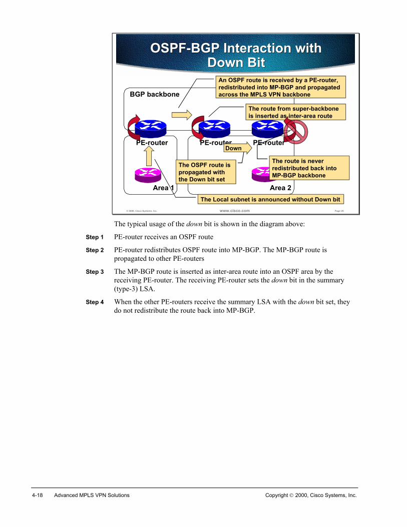
4-18 Advanced MPLS VPN Solutions Copyright 2000, Cisco Systems, Inc.
© 2000, Cisco Systems, Inc. www.cisco.com Page-20
OSPF-BGP Interaction withDown Bit
OSPF-BGP Interaction withDown Bit
Area 1
BGP backbone
PE-router
Area 2
PE-routerPE-router
The Local subnet is announced without Down bit
The route from super-backboneis inserted as inter-area route
An OSPF route is received by a PE-router,redistributed into MP-BGP and propagatedacross the MPLS VPN backbone
Down
The OSPF route ispropagated withthe Down bit set
The route is neverredistributed back intoMP-BGP backbone
The typical usage of the down bit is shown in the diagram above:
Step 1 PE-router receives an OSPF route
Step 2 PE-router redistributes OSPF route into MP-BGP. The MP-BGP route ispropagated to other PE-routers
Step 3 The MP-BGP route is inserted as inter-area route into an OSPF area by thereceiving PE-router. The receiving PE-router sets the down bit in the summary(type-3) LSA.
Step 4 When the other PE-routers receive the summary LSA with the down bit set, theydo not redistribute the route back into MP-BGP.
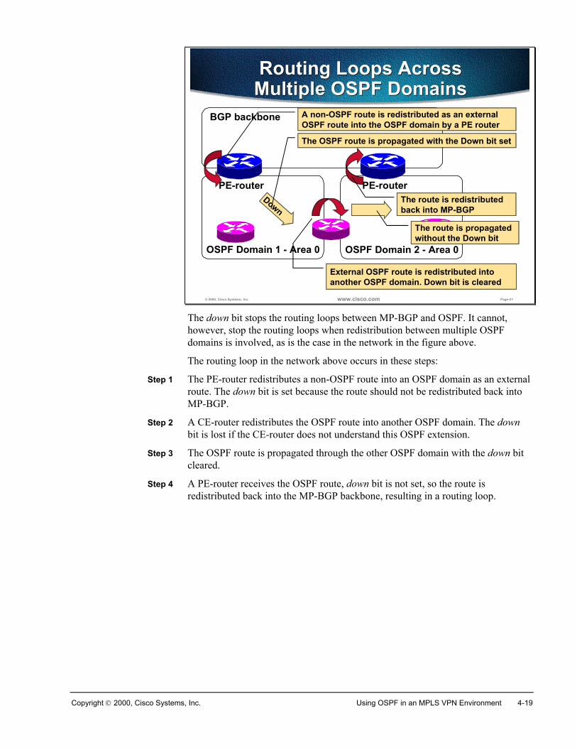
Copyright 2000, Cisco Systems, Inc. Using OSPF in an MPLS VPN Environment 4-19
© 2000, Cisco Systems, Inc. www.cisco.com Page-21
OSPF Domain 2 - Area 0OSPF Domain 1 - Area 0
Routing Loops AcrossMultiple OSPF DomainsRouting Loops AcrossMultiple OSPF Domains
BGP backbone
PE-router PE-router
External OSPF route is redistributed intoanother OSPF domain. Down bit is cleared
A non-OSPF route is redistributed as an externalOSPF route into the OSPF domain by a PE router
Down
The OSPF route is propagated with the Down bit set
The route is propagatedwithout the Down bit
The route is redistributedback into MP-BGP
The down bit stops the routing loops between MP-BGP and OSPF. It cannot,however, stop the routing loops when redistribution between multiple OSPFdomains is involved, as is the case in the network in the figure above.
The routing loop in the network above occurs in these steps:
Step 1 The PE-router redistributes a non-OSPF route into an OSPF domain as an externalroute. The down bit is set because the route should not be redistributed back intoMP-BGP.
Step 2 A CE-router redistributes the OSPF route into another OSPF domain. The downbit is lost if the CE-router does not understand this OSPF extension.
Step 3 The OSPF route is propagated through the other OSPF domain with the down bitcleared.
Step 4 A PE-router receives the OSPF route, down bit is not set, so the route isredistributed back into the MP-BGP backbone, resulting in a routing loop.
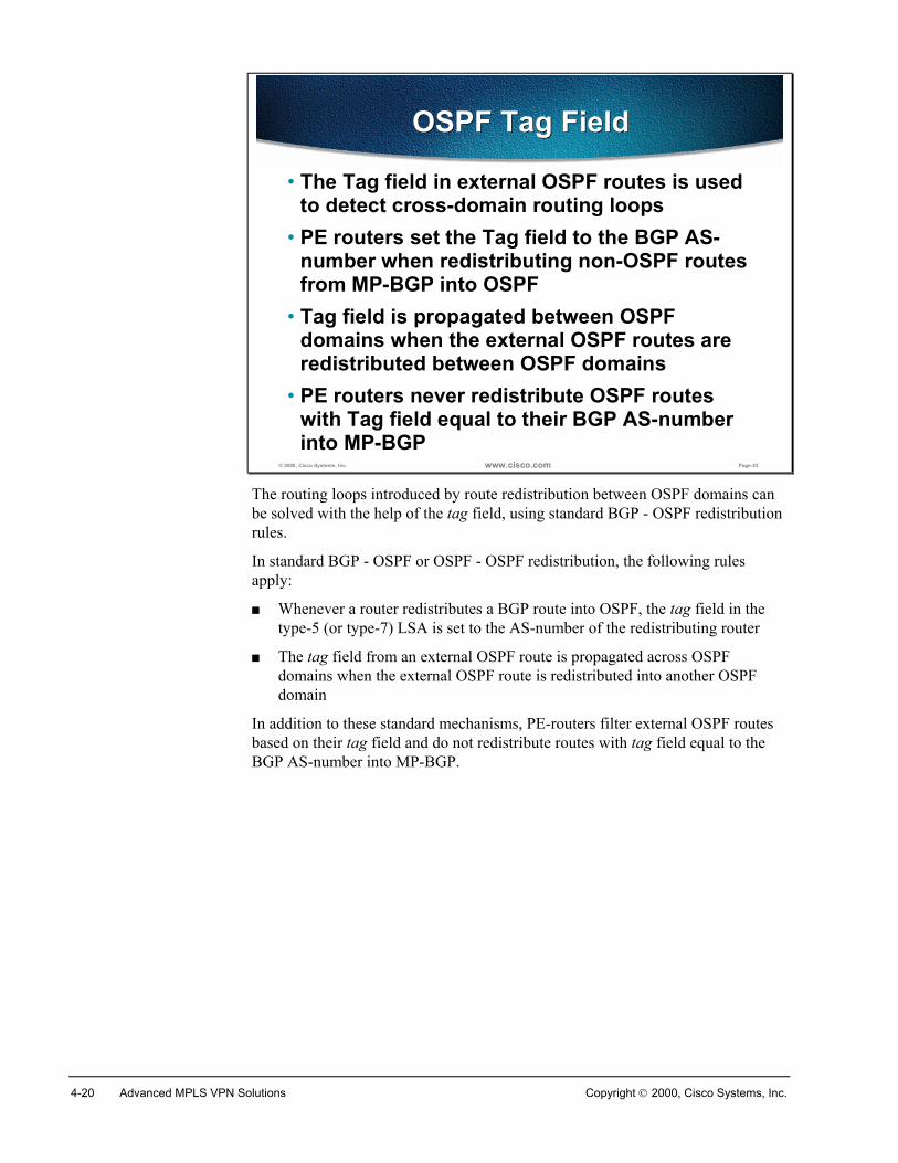
4-20 Advanced MPLS VPN Solutions Copyright 2000, Cisco Systems, Inc.
© 2000, Cisco Systems, Inc. www.cisco.com Page-22
OSPF Tag FieldOSPF Tag Field
• The Tag field in external OSPF routes is usedto detect cross-domain routing loops
• PE routers set the Tag field to the BGP AS-number when redistributing non-OSPF routesfrom MP-BGP into OSPF
• Tag field is propagated between OSPFdomains when the external OSPF routes areredistributed between OSPF domains
• PE routers never redistribute OSPF routeswith Tag field equal to their BGP AS-numberinto MP-BGP
The routing loops introduced by route redistribution between OSPF domains canbe solved with the help of the tag field, using standard BGP - OSPF redistributionrules.
In standard BGP - OSPF or OSPF - OSPF redistribution, the following rulesapply:
� Whenever a router redistributes a BGP route into OSPF, the tag field in thetype-5 (or type-7) LSA is set to the AS-number of the redistributing router
� The tag field from an external OSPF route is propagated across OSPFdomains when the external OSPF route is redistributed into another OSPFdomain
In addition to these standard mechanisms, PE-routers filter external OSPF routesbased on their tag field and do not redistribute routes with tag field equal to theBGP AS-number into MP-BGP.
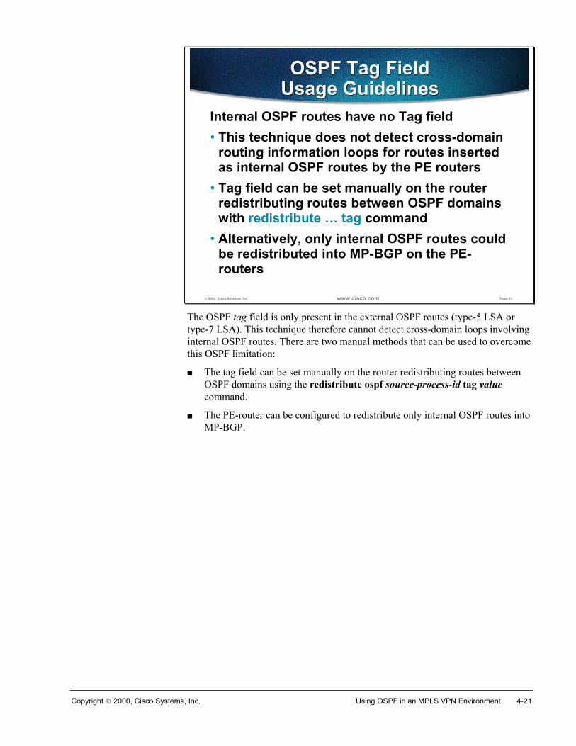
Copyright 2000, Cisco Systems, Inc. Using OSPF in an MPLS VPN Environment 4-21
© 2000, Cisco Systems, Inc. www.cisco.com Page-23
OSPF Tag FieldUsage GuidelinesOSPF Tag Field
Usage GuidelinesInternal OSPF routes have no Tag field• This technique does not detect cross-domain
routing information loops for routes insertedas internal OSPF routes by the PE routers
• Tag field can be set manually on the routerredistributing routes between OSPF domainswith redistribute … tag command
• Alternatively, only internal OSPF routes couldbe redistributed into MP-BGP on the PE-routers
The OSPF tag field is only present in the external OSPF routes (type-5 LSA ortype-7 LSA). This technique therefore cannot detect cross-domain loops involvinginternal OSPF routes. There are two manual methods that can be used to overcomethis OSPF limitation:
� The tag field can be set manually on the router redistributing routes betweenOSPF domains using the redistribute ospf source-process-id tag valuecommand.
� The PE-router can be configured to redistribute only internal OSPF routes intoMP-BGP.
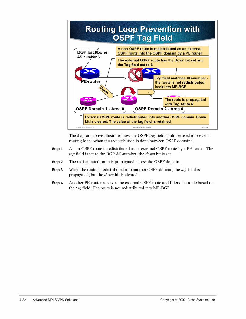
4-22 Advanced MPLS VPN Solutions Copyright 2000, Cisco Systems, Inc.
© 2000, Cisco Systems, Inc. www.cisco.com Page-24
OSPF Domain 2 - Area 0OSPF Domain 1 - Area 0
Routing Loop Prevention withOSPF Tag Field
Routing Loop Prevention withOSPF Tag Field
BGP backboneAS number 6
PE-router
External OSPF route is redistributed into another OSPF domain. Downbit is cleared. The value of the tag field is retained
A non-OSPF route is redistributed as an externalOSPF route into the OSPF domain by a PE router
The route is propagatedwith Tag set to 6
Tag field matches AS-number -the route is not redistributedback into MP-BGP
The external OSPF route has the Down bit set andthe Tag field set to 6
Down
The diagram above illustrates how the OSPF tag field could be used to preventrouting loops when the redistribution is done between OSPF domains.
Step 1 A non-OSPF route is redistributed as an external OSPF route by a PE-router. Thetag field is set to the BGP AS-number; the down bit is set.
Step 2 The redistributed route is propagated across the OSPF domain.
Step 3 When the route is redistributed into another OSPF domain, the tag field ispropagated, but the down bit is cleared.
Step 4 Another PE-router receives the external OSPF route and filters the route based onthe tag field. The route is not redistributed into MP-BGP.
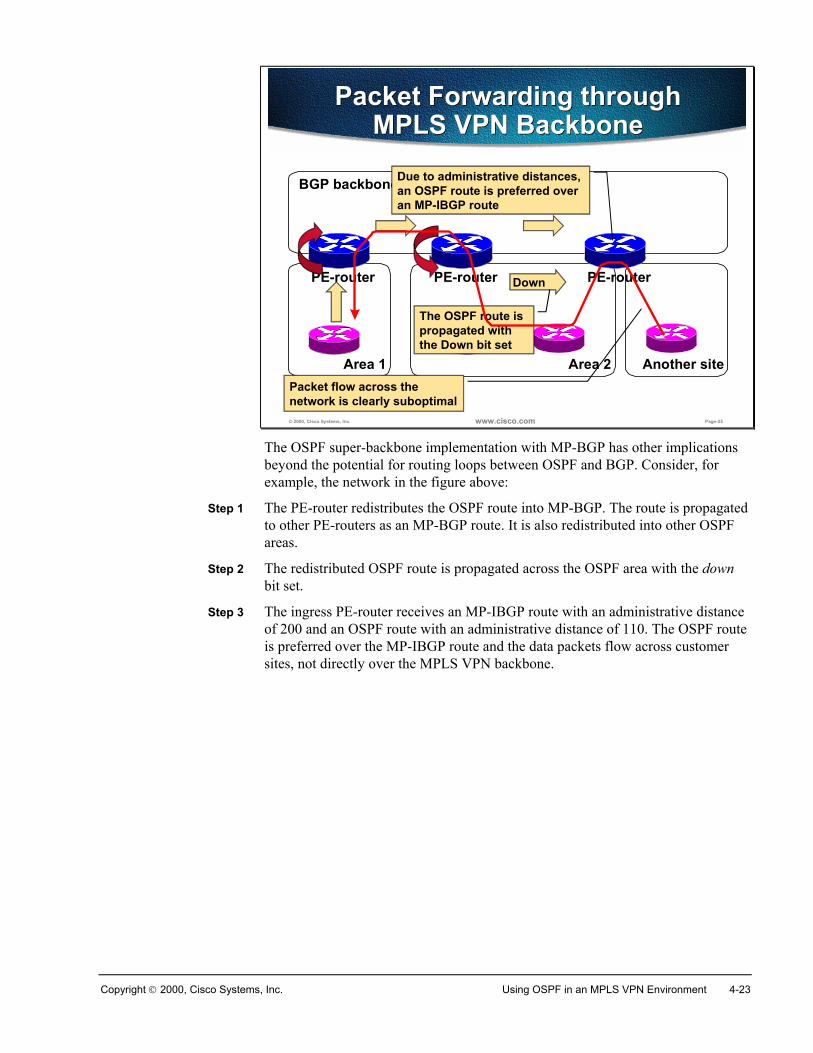
Copyright 2000, Cisco Systems, Inc. Using OSPF in an MPLS VPN Environment 4-23
© 2000, Cisco Systems, Inc. www.cisco.com Page-25
Another siteArea 1
BGP backbone
PE-router
Area 2
PE-routerPE-router
Packet Forwarding throughMPLS VPN Backbone
Packet Forwarding throughMPLS VPN Backbone
Due to administrative distances,an OSPF route is preferred overan MP-IBGP route
Down
The OSPF route ispropagated withthe Down bit set
Packet flow across thenetwork is clearly suboptimal
The OSPF super-backbone implementation with MP-BGP has other implicationsbeyond the potential for routing loops between OSPF and BGP. Consider, forexample, the network in the figure above:
Step 1 The PE-router redistributes the OSPF route into MP-BGP. The route is propagatedto other PE-routers as an MP-BGP route. It is also redistributed into other OSPFareas.
Step 2 The redistributed OSPF route is propagated across the OSPF area with the downbit set.
Step 3 The ingress PE-router receives an MP-IBGP route with an administrative distanceof 200 and an OSPF route with an administrative distance of 110. The OSPF routeis preferred over the MP-IBGP route and the data packets flow across customersites, not directly over the MPLS VPN backbone.
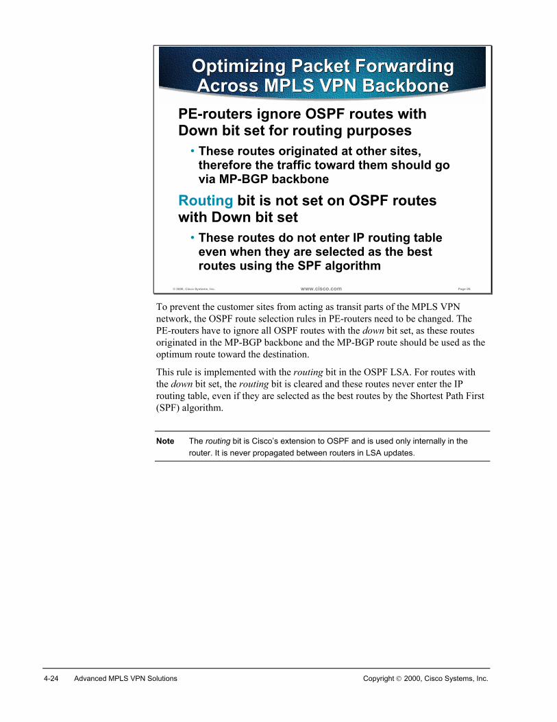
4-24 Advanced MPLS VPN Solutions Copyright 2000, Cisco Systems, Inc.
© 2000, Cisco Systems, Inc. www.cisco.com Page-26
Optimizing Packet ForwardingAcross MPLS VPN Backbone
Optimizing Packet ForwardingAcross MPLS VPN Backbone
PE-routers ignore OSPF routes withDown bit set for routing purposes
• These routes originated at other sites,therefore the traffic toward them should govia MP-BGP backbone
Routing bit is not set on OSPF routeswith Down bit set
• These routes do not enter IP routing tableeven when they are selected as the bestroutes using the SPF algorithm
To prevent the customer sites from acting as transit parts of the MPLS VPNnetwork, the OSPF route selection rules in PE-routers need to be changed. ThePE-routers have to ignore all OSPF routes with the down bit set, as these routesoriginated in the MP-BGP backbone and the MP-BGP route should be used as theoptimum route toward the destination.
This rule is implemented with the routing bit in the OSPF LSA. For routes withthe down bit set, the routing bit is cleared and these routes never enter the IProuting table, even if they are selected as the best routes by the Shortest Path First(SPF) algorithm.
Note The routing bit is Cisco’s extension to OSPF and is used only internally in therouter. It is never propagated between routers in LSA updates.
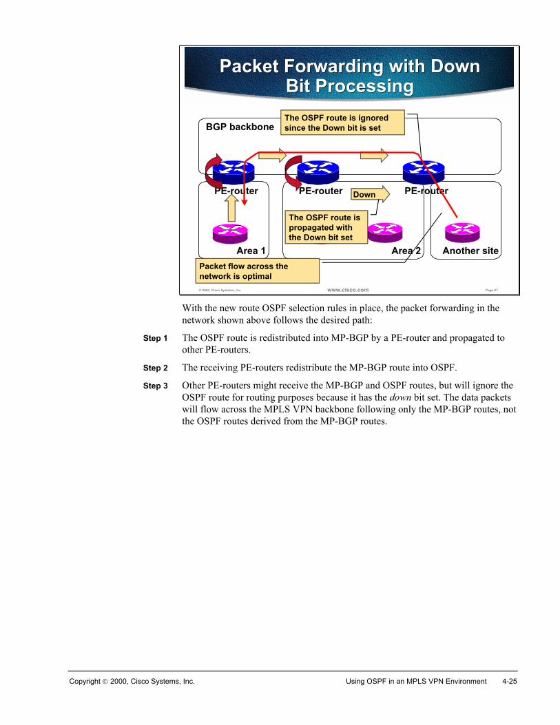
Copyright 2000, Cisco Systems, Inc. Using OSPF in an MPLS VPN Environment 4-25
© 2000, Cisco Systems, Inc. www.cisco.com Page-27
Another siteArea 1
BGP backbone
PE-router
Area 2
PE-routerPE-router
Packet Forwarding with DownBit Processing
Packet Forwarding with DownBit ProcessingThe OSPF route is ignoredsince the Down bit is set
Down
The OSPF route ispropagated withthe Down bit set
Packet flow across thenetwork is optimal
With the new route OSPF selection rules in place, the packet forwarding in thenetwork shown above follows the desired path:
Step 1 The OSPF route is redistributed into MP-BGP by a PE-router and propagated toother PE-routers.
Step 2 The receiving PE-routers redistribute the MP-BGP route into OSPF.
Step 3 Other PE-routers might receive the MP-BGP and OSPF routes, but will ignore theOSPF route for routing purposes because it has the down bit set. The data packetswill flow across the MPLS VPN backbone following only the MP-BGP routes, notthe OSPF routes derived from the MP-BGP routes.
4-26 Advanced MPLS VPN Solutions Copyright 2000, Cisco Systems, Inc.
SummaryThe MPLS VPN architecture introduces a routing model where a BGP backboneis inserted into the customer network. Traditional OSPF - BGP interactions wouldimply that the OSPF routes received from one customer site would be inserted asexternal OSPF routes into other customer sites. As the external OSPF routes aretreated differently from internal OSPF routes and the customer OSPF routingoften relies on properties of various OSPF route types, this option is notacceptable. A different model is needed where the MPLS VPN backbone would beimplemented transparently to the customer.
The OSPF super-backbone was introduced in MPLS VPN architecture to supportthe transparency requirements. The OSPF super-backbone, although implementedwith MP-BGP, looks like a regular area to the CE-routers and the PE-routers looklike Area Border Routers (ABR) even though they are in reality redistributingroutes between MP-BGP and OSPF.
Additional extended BGP communities are used to propagate the OSPF route typeacross an MP-BGP backbone. The OSPF route type carried in the MP-BGP updatereceived by the PE-router is used to generate a summary LSA in the OSPFtopology database. An additional bit (called the down bit) is used in the Optionsfield of the OSPF header to prevent routing loops between MP-BGP and OSPF.The same bit is also used on the PE-routers to prefer MP-BGP routes over OSPFroutes derived from MP-BGP routes through redistribution.
Review QuestionsAnswer the following questions:
� Why is the OSPF super-backbone needed in MPLS VPN environments?
� What is the interaction between Area 0 and a super-backbone?
� What is the interaction between a super-backbone and other areas?
� How are OSPF route attributes propagated across an MPLS VPN backbone?
� What is the purpose of the Down bit in an LSA header?
� What is the influence of the Down bit on route selection process? Why is thisinfluence needed?
Copyright 2000, Cisco Systems, Inc. Using OSPF in an MPLS VPN Environment 4-27
Configuring and Monitoring OSPF in an MPLS VPNEnvironment
ObjectivesUpon completion of this section, you will be able to perform the following tasks:
� Configure OSPF in a customer VPN
� Monitor MPLS VPN-specific attributes in an OSPF topology database
� Monitor OSPF-specific extended communities in an MP-BGP table
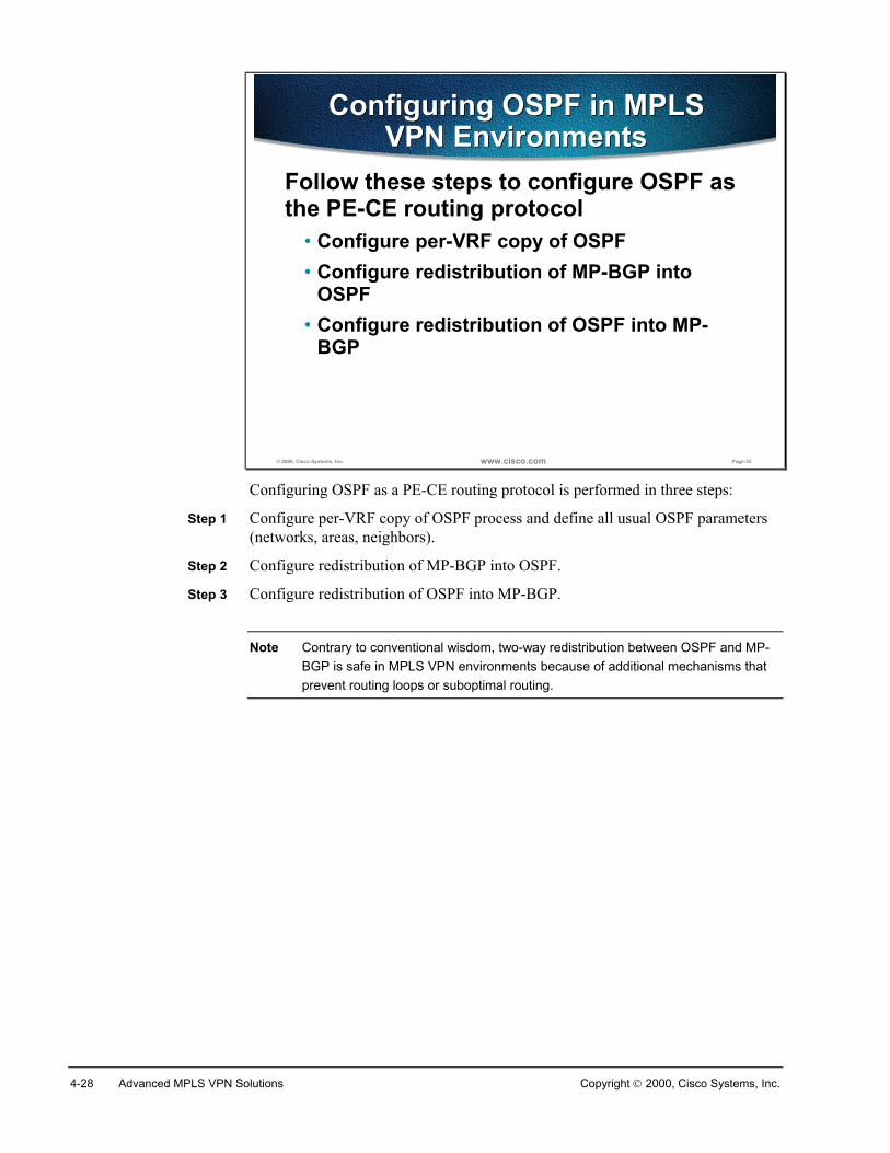
4-28 Advanced MPLS VPN Solutions Copyright 2000, Cisco Systems, Inc.
© 2000, Cisco Systems, Inc. www.cisco.com Page-32
Configuring OSPF in MPLSVPN Environments
Configuring OSPF in MPLSVPN Environments
Follow these steps to configure OSPF asthe PE-CE routing protocol
• Configure per-VRF copy of OSPF• Configure redistribution of MP-BGP into
OSPF• Configure redistribution of OSPF into MP-
BGP
Configuring OSPF as a PE-CE routing protocol is performed in three steps:
Step 1 Configure per-VRF copy of OSPF process and define all usual OSPF parameters(networks, areas, neighbors).
Step 2 Configure redistribution of MP-BGP into OSPF.
Step 3 Configure redistribution of OSPF into MP-BGP.
Note Contrary to conventional wisdom, two-way redistribution between OSPF and MP-BGP is safe in MPLS VPN environments because of additional mechanisms thatprevent routing loops or suboptimal routing.
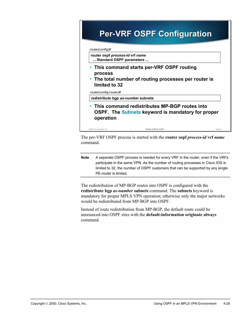
Copyright 2000, Cisco Systems, Inc. Using OSPF in an MPLS VPN Environment 4-29
© 2000, Cisco Systems, Inc. www.cisco.com Page-33
router ospf process-id vrf name ... Standard OSPF parameters ...
router(config)#
• This command starts per-VRF OSPF routingprocess
• The total number of routing processes per router islimited to 32
Per-VRF OSPF ConfigurationPer-VRF OSPF Configuration
redistribute bgp as-number subnetsrouter(config-router)#
• This command redistributes MP-BGP routes intoOSPF. The Subnets keyword is mandatory for properoperation
The per-VRF OSPF process is started with the router ospf process-id vrf namecommand.
Note A separate OSPF process is needed for every VRF in the router, even if the VRFsparticipate in the same VPN. As the number of routing processes in Cisco IOS islimited to 32, the number of OSPF customers that can be supported by any singlePE-router is limited.
The redistribution of MP-BGP routes into OSPF is configured with theredistribute bgp as-number subnets command. The subnets keyword ismandatory for proper MPLS VPN operation; otherwise only the major networkswould be redistributed from MP-BGP into OSPF.
Instead of route redistribution from MP-BGP, the default route could beannounced into OSPF sites with the default-information originate alwayscommand.
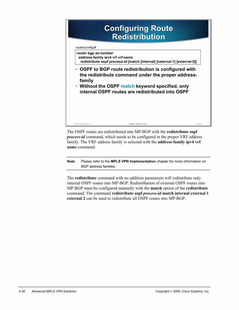
4-30 Advanced MPLS VPN Solutions Copyright 2000, Cisco Systems, Inc.
© 2000, Cisco Systems, Inc. www.cisco.com Page-34
router bgp as-number address-family ipv4 vrf vrf-name redistribute ospf process-id [match [internal] [external-1] [external-2]]
router(config)#
• OSPF to BGP route redistribution is configured withthe redistribute command under the proper address-family
• Without the OSPF match keyword specified, onlyinternal OSPF routes are redistributed into OSPF
Configuring RouteRedistribution
Configuring RouteRedistribution
The OSPF routes are redistributed into MP-BGP with the redistribute ospfprocess-id command, which needs to be configured in the proper VRF addressfamily. The VRF address family is selected with the address-family ipv4 vrfname command.
Note Please refer to the MPLS VPN Implementation chapter for more information onBGP address families.
The redistribute command with no addition parameters will redistribute onlyinternal OSPF routes into MP-BGP. Redistribution of external OSPF routes intoMP-BGP must be configured manually with the match option of the redistributecommand. The command redistribute ospf process-id match internal external 1external 2 can be used to redistribute all OSPF routes into MP-BGP.
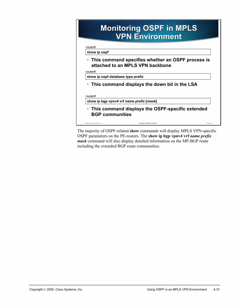
Copyright 2000, Cisco Systems, Inc. Using OSPF in an MPLS VPN Environment 4-31
© 2000, Cisco Systems, Inc. www.cisco.com Page-35
show ip ospfrouter#
• This command specifies whether an OSPF process isattached to an MPLS VPN backbone
Monitoring OSPF in MPLSVPN Environment
Monitoring OSPF in MPLSVPN Environment
show ip ospf database type prefixrouter#
• This command displays the down bit in the LSA
show ip bgp vpnv4 vrf name prefix [mask]router#
• This command displays the OSPF-specific extendedBGP communities
The majority of OSPF-related show commands will display MPLS VPN-specificOSPF parameters on the PE-routers. The show ip bgp vpnv4 vrf name prefixmask command will also display detailed information on the MP-BGP routeincluding the extended BGP route communities.
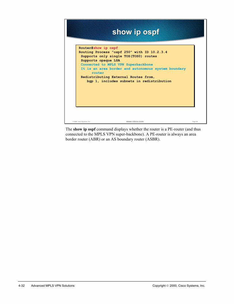
4-32 Advanced MPLS VPN Solutions Copyright 2000, Cisco Systems, Inc.
© 2000, Cisco Systems, Inc. www.cisco.com Page-36
show ip ospfshow ip ospf
Router#show ip ospfRouting Process "ospf 250" with ID 10.2.3.4 Supports only single TOS(TOS0) routes Supports opaque LSA Connected to MPLS VPN Superbackbone It is an area border and autonomous system boundary
router Redistributing External Routes from, bgp 1, includes subnets in redistribution
Router#show ip ospfRouting Process "ospf 250" with ID 10.2.3.4 Supports only single TOS(TOS0) routes Supports opaque LSA Connected to MPLS VPN Superbackbone It is an area border and autonomous system boundary
router Redistributing External Routes from, bgp 1, includes subnets in redistribution
The show ip ospf command displays whether the router is a PE-router (and thusconnected to the MPLS VPN super-backbone). A PE-router is always an areaborder router (ABR) or an AS boundary router (ASBR).
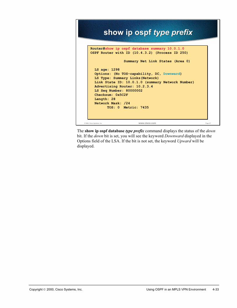
Copyright 2000, Cisco Systems, Inc. Using OSPF in an MPLS VPN Environment 4-33
© 2000, Cisco Systems, Inc. www.cisco.com Page-37
show ip ospf type prefixshow ip ospf type prefix
Router#show ip ospf database summary 10.0.1.0OSPF Router with ID (10.4.3.2) (Process ID 250) Summary Net Link States (Area 0) LS age: 1298 Options: (No TOS-capability, DC, Downward) LS Type: Summary Links(Network) Link State ID: 10.0.1.0 (summary Network Number) Advertising Router: 10.2.3.4 LS Seq Number: 80000002 Checksum: 0x5C2F Length: 28 Network Mask: /24 TOS: 0 Metric: 7435
Router#show ip ospf database summary 10.0.1.0OSPF Router with ID (10.4.3.2) (Process ID 250) Summary Net Link States (Area 0) LS age: 1298 Options: (No TOS-capability, DC, Downward) LS Type: Summary Links(Network) Link State ID: 10.0.1.0 (summary Network Number) Advertising Router: 10.2.3.4 LS Seq Number: 80000002 Checksum: 0x5C2F Length: 28 Network Mask: /24 TOS: 0 Metric: 7435
The show ip ospf database type prefix command displays the status of the downbit. If the down bit is set, you will see the keyword Downward displayed in theOptions field of the LSA. If the bit is not set, the keyword Upward will bedisplayed.
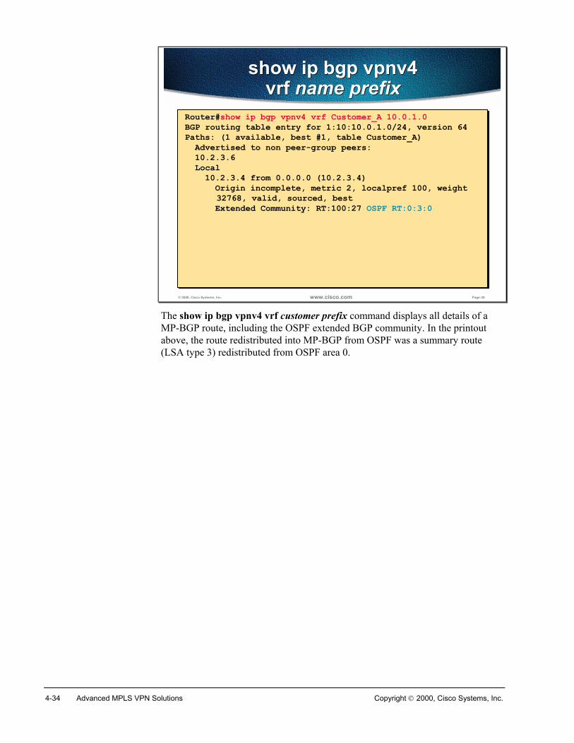
4-34 Advanced MPLS VPN Solutions Copyright 2000, Cisco Systems, Inc.
© 2000, Cisco Systems, Inc. www.cisco.com Page-38
show ip bgp vpnv4vrf name prefix
show ip bgp vpnv4vrf name prefix
Router#show ip bgp vpnv4 vrf Customer_A 10.0.1.0BGP routing table entry for 1:10:10.0.1.0/24, version 64Paths: (1 available, best #1, table Customer_A) Advertised to non peer-group peers: 10.2.3.6 Local 10.2.3.4 from 0.0.0.0 (10.2.3.4) Origin incomplete, metric 2, localpref 100, weight
32768, valid, sourced, best Extended Community: RT:100:27 OSPF RT:0:3:0
The show ip bgp vpnv4 vrf customer prefix command displays all details of aMP-BGP route, including the OSPF extended BGP community. In the printoutabove, the route redistributed into MP-BGP from OSPF was a summary route(LSA type 3) redistributed from OSPF area 0.
Copyright 2000, Cisco Systems, Inc. Using OSPF in an MPLS VPN Environment 4-35
SummaryThe OSPF process in a VRF is started with the router ospf process vrf namecommand. As the overall number of routing processes per router is limited to 32, asingle PE-router can serve only a small number of VRFs.
Two-way redistribution between BGP and OSPF is usually configured. Theredistribution is safe because of additional attributes introduced with the super-backbone architecture.
By default, only major networks are redistributed into OSPF. Redistribution ofsubnets needs to be configured with the redistribute … subnets command.
By default, only internal OSPF routes are redistributed from OSPF into MP-BGP.Redistribution of external routes has to be configured with the redistribute …match route-type-list command.
The show ip ospf command will display whether a router is a PE-router connectedto the MPLS VPN backbone. The detailed printouts from the show ip ospfdatabase command will display the value of the down bit. The detailed printoutsfrom the show ip bgp command will display the OSPF-specific extended BGPcommunity.
Review QuestionsHow can you verify if an OSPF route was received from a local OSPF router orthrough an MPLS VPN backbone?
� How can you verify if your router is participating in an OSPF super-backbone?
� How can you display OSPF-related extended communities attached to a route?
4-36 Advanced MPLS VPN Solutions Copyright 2000, Cisco Systems, Inc.
SummaryAfter completing this chapter, you should be able to perform the following tasks:
� Describe OSPF operation inside a VPN
� Describe the enhanced OSPF hierarchical model
� Describe the interactions between OSPF and MP-BGP
� Use OSPF as the PE-CE routing protocol in a complex MPLS VPNenvironment
Copyright 2000, Cisco Systems, Inc. Using OSPF in an MPLS VPN Environment 4-37
Answers to Review Questions
Using OSPF as the PE-CE Protocol in an MPLS VPN Environment� Why is the OSPF super-backbone needed in MPLS VPN environments?
The super-backbone is needed to ensure that the internal OSPF routesare not inserted as external OSPF routes into other customer sites.
� What is the interaction between Area 0 and a super-backbone?
The super-backbone appears as just another OSPF area to the routers inthe OSPF backbone area (area 0).
� What is the interaction between a super-backbone and other areas?
The super-backbone appears as area 0 (backbone area) to non-backboneOSPF routers.
� How are OSPF route attributes propagated across MPLS VPN backbone?
OSPF area, route type, and metric type are propagated in an extendedBGP community. OSPF cost or external metric is propagated in the BGPMED attribute.
� What is the purpose of the Down bit in an LSA header?
The down bit prevents redistribution loops between MP-BGP and OSPF.It also ensures proper route selection in the PE-routers.
� What is the influence of the Down bit on the route selection process? Why isthis influence needed?
OSPF routes with the Down bit set are never entered in the routing table.This ensures that the MP-IBGP routes from which the OSPF routes werederived will be used for packet forwarding even though the IBGP routeshave a higher administrative distance than the OSPF routes.
Configuring and Monitoring OSPF in an MPLS VPN Environment� How can you verify if your router is participating in an OSPF super-
backbone?
Use the show ip ospf command.
� How can you display OSPF-related extended communities attached to a route?
Use the show ip bgp vpnv4 vrf name prefix command.

4-38 Advanced MPLS VPN Solutions Copyright 2000, Cisco Systems, Inc.