Embed Size (px)
Citation preview

Advanced Lean-Burn DI Spark Ignition Fuels Research
Magnus Sjöberg
Sandia National Laboratories May 15th, 2012
This presentation does not contain any proprietary, confidential, or otherwise restricted information
Project ID: FT006

2
Overview
• Project provides science to support industry to develop advanced lean/dilute-burn SI engines for non-petroleum fuels.
• Project directions and continuation are reviewed annually.
• Project funded by DOE/VT via Kevin Stork.
• FY11 - $650 K • FY12 - $750 K
Timeline Budget
Barriers • Inadequate data and predictive tools for
fuel property effects on combustion and engine efficiency optimization.
• Evaluate new fuels and fuel blends for efficiency, emissions, and operating stability with advanced SI combustion.
1. Lean, unthrottled DISI with spray-guided combustion.
2. Well-mixed charge and high boost.
Partners / Collaborators • PI: Sandia (M. Sjöberg) • 15 Industry partners in the Advanced
Engine Combustion MOU. • General Motors - Hardware. • D.L. Reuss (formerly at GM). • LLNL (Pitz et al.) – Mechanisms and
Flame-Speed Calculations. • LLNL (Aceves et al.) - CFD Modeling. • Sandia Spray Combustion & Heavy-Duty
Diesel Labs (Pickett & Musculus). • USC-LA (Egolfopoulos) - Flame
Measurements.

3
Objectives - Relevance Project goals are to provide the science-base needed to understand: •How emerging future fuels will impact the combustion systems of new
highly-efficient DISI light-duty engines currently being developed. •How the fuels and combustion systems can be tailored to each other to
maximize thermal efficiency. •Current focus is on E85 and gasoline. Expand to other fuel blends (e.g. E15-E30)
and components (e.g. butanol and iso-pentanol) based on industry interest. DISI with spray-guided stratified charge combustion system
– Has demonstrated strong potential for throttle-less high-efficiency engine operation. – Plagued by misfires and partial burns, especially for low-NOx operation. – Mastering NOx / Soot / Combustion Stability trade-offs is key to success. – These processes are strongly affected by fuel properties.
•Study performance and exhaust emissions for lean stratified operation and examine the effects of fuel properties.
•Develop / employ high-speed optical diagnostics to understand advanced combustion and mitigate potential barriers (e.g. ensure robust combustion).
•Conduct supporting modeling for understanding of governing fundamentals.

4
•Combine metal- and optical-engine experiments and modeling to develop a broad understanding of the impact of fuel properties on DISI combustion processes.
•First, conduct performance testing with a state-of-the-art all-metal engine configuration over wide ranges of operating conditions and alternative fuels.
– Speed, load, intake pressure, EGR, and stratification level. Quantify engine operation and develop combustion statistics.
•Second, apply a combination of optical and conventional diagnostics to develop the understanding needed to mitigate barriers to high efficiency, robustness, and low emissions.
– Include full spectrum of phenomena; from intake flow, fuel-air mixing and ignition, to development of flame, and endgas autoignition (knock).
Supporting modeling: •Conduct chemical-kinetics modeling of flame-speed for detailed knowledge of
governing fundamentals. – Collaborate on validation experiments and mechanism development. – Collaborate on the thermodynamics of fuel-air mixing and vaporization.
•Collaborate on CFD modeling of in-cylinder flows and combustion.
Approach

5
Approach / Research Engine Two configurations of drop-down single-cylinder engine. Bore = 86.0 mm, Stroke = 95.1 mm, 0.55 liter swept volume. • All-metal: Metal-ring pack and air/oil-jet cooling of piston. • Optical: Pent-roof window, piston-bowl window, and 45° Bowditch mirror. • Identical geometry for both configurations, so minimal discrepancy between
performance testing and optical tests. • 8-hole injector with 60° included angle ⇒
22° between each pair of spray center lines. Spark gap is in between two sprays.

6
Technical Accomplishments
• Performed a comparative study of stratified operation with E85 and gasoline, examining the potential to accomplish low NOx / PM operation.
– Demonstrated the use of near-TDC fuel injection to enable ultra-low NO and soot with E85. • Optical engine experiments:
– Commissioned optical version of the engine. – Performed high-speed imaging studies of stratified E85 operation. – Natural luminosity, Mie-imaging of fuel-spray development, and initial fuel-PLIF. – Identified ignition and flame-spread issues leading to partial burns. – Characterized laser-sheet quality of high-speed PIV laser.
• Used CHEMKIN to investigate the influence of E85’s strong vaporization cooling on the laminar flame speed for wide ranges of φ.
• Set up and validated GT-Power model over wide ranges of speed and boost. – Used high-speed imaging of valve motion as model input.
• Continued the examination of the direct effect of vaporization cooling on the thermal efficiency for E85 and gasoline.
– Quantified the effects of injection timing and pressure.

7
Emissions Study Parameter Current Study
CR 12
Piston Bowl ∅ 46 mm
Swirl Index 0 or 2.7 (most data)
Valve Timings For Minimal Residual Level
Injector & Spray Targeting
Bosch 8 x 60° Straddling Spark
Injection Pressure 170 bar
# of Injections Single
Spark Energy 106 mJ
Tcoolant 60°C
Tin 26-28°C
Engine Speed 1000 rpm
Intake Pressure 95 kPa
Pexhaust 100 kPa
IMEPn 250-380 kPa
Start of Injection (SOI) -37 to -5°CA
Spark Timing (ST) -36 to 1°CA
EGR / [O2]in 21 – 14.5% O2
Fuel Type E85, Gasoline
• The traditional SI engine has poor thermal efficiency at low loads.
• Overall lean but stratified combustion can improve fuel economy.
• Low engine-out NOx and PM is required to avoid expensive lean-NOx aftertreatment and particulate filter.
• The parameter space is huge. • Grouped as hardware, static parameters &
operating variables. • Relatively low in-cylinder temperatures. • Acquired data for 500 cycles per steady-
state operating point. • Unless noted, stratified cases have
spark timing (ST) for lowest standard deviation (SD) of IMEPn.

8
• Apply N2 dilution to examine potential for low NOx operation.
• Gasoline shows clear trade-off. Engine- out soot is governed by soot burn-out?
• Low NO is possible, but at the expense of soot and stability.
• With E85, can reach inside the US2010 NO/PM box, using near-TDC injection.
– NO2 contribution may be substantial. – Future study.
150
200
250
300
350
400
0 100 200 300 400 500Cycle number [-]IM
EPn [
kPa]
Gasoline, [O2] = 21%
SOIa = -31°CASpark -23°CA
Reaching Inside the NO/PM Box
00.0050.01
0.0150.02
0.0250.03
0.0350.04
0.0450.05
0 2 4 6 8 10 12 14 16ISNO [g/kWh]
ISPM
[g/k
Wh]
Gasoline, SOI = -31°CA, IMEPn = 370 kPaE85, SOI = -31°CA, IMEPn = 370 kPaE85, SOI = -23°CA, IMEPn = 370 kPaE85, SOI = -23°CA, IMEPn = 250 kPaE85, SOI = -6°CA, IMEPn = 260 kPa
21% Intake [O2]
17%
14.5%
21%19.5%
18%
18%
00.0050.01
0.0150.02
0.0250.03
0.0350.04
0.0450.05
0 0.25 0.5 0.75 1 1.25 1.5 1.75 2ISNO [g/kWh]
ISPM
[g/k
Wh]
14.5%
21%
18%
18%
19%
17%
150
200
250
300
350
400
0 100 200 300 400 500Cycle number [-]
IMEP
n [kP
a]
111118T[O2] = 14.5%
SOIa = -31°CASpark -24°CA

9
a. SOI retard strongly reduces NO emissions. b. Lower average peak combustion temperatures. c. Later CA50, so less time for thermal NO formation. d. Closely-coupled injection and combustion.
– Higher mixing rates may limit time spent at NO-producing temperatures.
e. Compared to gasoline, E85 generally requires earlier spark for highest stability.
– This difference is accentuated for SOI retard. – For near-TDC injection, spark discharge starts well
before fuel is present in the cylinder! f. How can this help stability?
– Use high-speed imaging. • Spark at SOI or earlier
counteracts CA50 retard with SOI retard.
– Spark of gasoline is near EOI, so does not allow much SOI retard.
Effects of Injection Timing Retard
-8
-6
-4
-2
0
2
4
6
8
10
-40 -35 -30 -25 -20 -15 -10 -5Start of Injection [°CA]
SOI t
o Sp
ark
[°C
A]
SOI
EOI - E85, 370 kPa
EOI - Gasoline & E85, 260 kPa
050
100150200250300350
-40 -35 -30 -25 -20 -15 -10 -5Start of Injection [°CA]
NO
[ppm
]
6 39
1000
1100
1200
1300
1400
1500
-40 -35 -30 -25 -20 -15 -10 -5Start of Injection [°CA]
Peak
. Avg
. Tem
p. [K
]
-12-8-4048
12
-40 -35 -30 -25 -20 -15 -10 -5Start of Injection [°CA]
CA
50 [°
CA
]
0
5
10
15
20
25
-40 -35 -30 -25 -20 -15 -10 -5Start of Injection [°CA]
EOI t
o C
A50
[°C
A]
012345
-40 -35 -30 -25 -20 -15 -10 -5Start of Injection [°CA]
CO
V IM
EPn [
%]
a.
b.
c.
d.
f.
e.
-8
-6
-4
2
-40 -35 -30 -25 -20Start of Injecti
SO
Gasoline, IMEPn = 370 kPa,[O2] = 16.5%E85, IMEPn = 370 kPa, [O2] = 17.5-18%E85, IMEPn = 260 kPa, [O2] = 19%

10
• SOI = -6°CA can provide single-digit NO. • N2-dilution sweep shows trade-offs between
NO-Stability-CE-TE. • The NO-Stability trade-off is superior to other
conditions with earlier SOI. • Study 19% point further. • Has very low NO, but increased combustion
efficiency and stability would enable more fuel-economy gain.
– Up to +27% relative stoichiometric operation.
N2-sweep for SOI = -6°CA
0
10
20
3040
50
60
70
18 18.5 19 19.5 20 20.5 21Intake O2 [%]
Exha
ust N
O [p
pm]
0
1
2
34
5
6
7
Cor
r. SD
of I
MEP
n [%
]
NOSD of IMEPn
E85, IMEPn = 260 kPa
0
1
2
3
4
5
6
0 0.5 1 1.5 2 2.5 3 3.5 4ISNO [g/kWh]
Cor
r. SD
of I
MEP
n [%
]
Gasoline, SOI = -31°CA, IMEPn = 370 kPaE85, SOI = -31°CA, IMEPn = 370 kPaE85, SOI = -23°CA, IMEPn = 250 kPaE85, SOI = -6°CA IMEPn = 260 kPa
21% Intake [O2]20%
19.5%
19%
18.5%
28
30
32
34
36
38
40
18 18.5 19 19.5 20 20.5 21Intake O2 [%]
Ther
mal
Eff.
[%]
70
75
80
85
90
95
100
Com
b. E
ff. [%
]
SOI = -6°CA, Thermal Eff.Phi = 1, Thermal Eff.SOI = -6°CA, Comb. Eff.
+27%
200
220
240
260
280
0 100 200 300 400 500Cycle number [-]
IMEP
n [k
Pa]
111122S[O2] = 21%
200
220
240
260
280
0 100 200 300 400 500Cycle number [-]
IMEP
n [k
Pa]
111122N[O2] = 19%
SOI = -6°CASpark -11°CA

11
Imaging Setup / Spark-Sweep • Bowditch: Phantom v7.10 with f = 180 mm lens.
– Wide-angle view using concave window. • Side window: Phantom v7.1 with f = 50 mm lens. • Broadband imaging - CMOS chip. • Pulsed high-intensity LED for Mie-scattering.
– 5µs or 10µs pulse length. – Skip-illumination for near-simultaneous
Mie-scattering and flame imaging. • 3/12 - skipfire operation for realistic residuals. • Spark = -12°CA consistently misfire-free. • Spark during fuel injection leads to high misfire rate.
0
20
40
0 1 2 3 4 5 6 7 8 9 10 11 12 13Cycle #
Pres
sure
[bar
]0
10
20
30
40
50
60
70
80
-15 -13 -11 -9 -7 -5 -3 -1 1Spark Timing [°CA]
Mis
fire
Prob
abili
ty [%
]
All-MetalOptical, Skipfire
Fuel Injection
[O2] = 19%SOIa = -6°CA
1
2

12
High-Speed Imaging, SOI = -6ϲ/!
• Statistically selected cycle. • Combined Mie and natural
luminosity.
• Closely coupled injection and ignition leads to highly turbulent combustion.
-200-100
0100200300
Spar
k C
urre
nt [m
A]
FigureNo FuelAverage
-505
1015202530
-20 -10 0 10 20 30 40Crank Angle [°CA]
P cyl [b
ar],
AH
RR
[J/°]
Inj.
Spark = -12°CA, Intake [O2] = 19%, Exhaust NO = 6 ppm

13
• SOI = -6°
CA, spark = -12°CA. • Correlation with IMEP.
– Total Burn. – Early flame intensity.
• Weak cycles have odd flow near spark gap.
• Shows need to manage stochastic processes for better engine performance.
Imaging of Cyclic Variability
0
5
10
15
20
25
30
210 230 250 270 290IMEPg [kPa]
50
100
150
200
250
300
350
Imag
e In
tens
ity @
0.3
°CA
Cum
. AH
RR
[J]
14
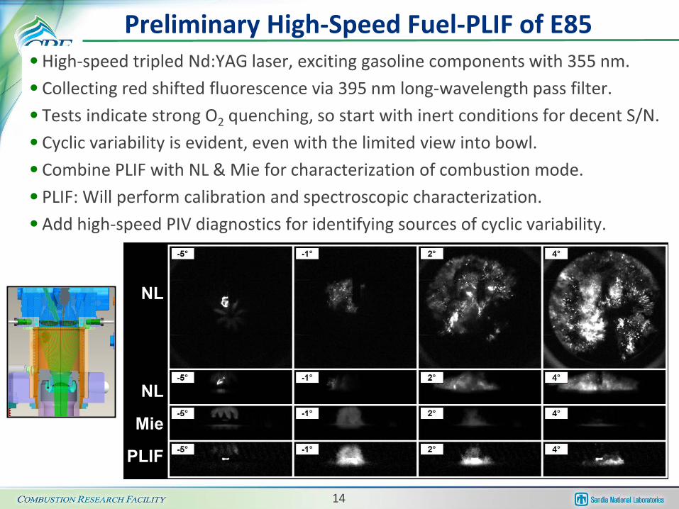
• High-speed tripled Nd:YAG laser, exciting gasoline components with 355 nm. • Collecting red shifted fluorescence via 395 nm long-wavelength pass filter. • Tests indicate strong O2 quenching, so start with inert conditions for decent S/N. • Cyclic variability is evident, even with the limited view into bowl. • Combine PLIF with NL & Mie for characterization of combustion mode. • PLIF: Will perform calibration and spectroscopic characterization. • Add high-speed PIV diagnostics for identifying sources of cyclic variability.
Preliminary High-Speed Fuel-PLIF of E85
NL
NL
Mie
PLIF

15
Fuel Vaporization / Flame Speed • E85 experiments with near-TDC fuel injection beg for more insights. For example: • What enables E85 to be ignited in the head of fuel jet, while gasoline fuel jets misfire? • Why are exhaust soot levels so low, despite flame spread prior to fuel/air mixing? • Why are NO levels so low? • Use optical techniques and modeling to answer these questions (future work). • First, however, examine some of the fundamentals. • E85’s large latent heat of vaporization and high oxygen content: 1.Prevents very rich gas-phase mixtures. For E85 φmax ≈ 5, whereas φmax ≈ 15 for gasoline. 2.Makes richer zones much cooler. CHEMKIN predicts strongly suppressed combustion
activity in these rich zones. Contributes to suppress soot formation.
0
10
20
30
40
50
0 0.5 1 1.5 2 2.5 3 3.5 4 4.5 5Fuel/Air-Equivalence Ratio [φ ]
Lam
inar
Fla
me
Spee
d [c
m/s
] Mixing and Heating Downstreamof Liquid LengthConstant Temperature
EthanolPressure = 25 bar
[O2] = 18.5%
0
2
4
6
8
10
12
14
16
350 400 450 500 550 600 650 700 750 800Fuel Jet Mixing Temperature [K]
Fuel
/Air
Equi
vale
nce
Rat
io [-
]
iso-Octane(gasoline surrogate)
Ethanol(E85 surrogate)
Liquid Length Solid = Ethanol Dashed = iso-Octane
φ = 1

16
Fuel Vaporization / Thermal Efficiency
• Efficiency study at IMEPn = 370 kPa shows that TE-gain of stratified operation relative stoichiometric operation is 4% lower for E85.
– +24% for gasoline, +20% for E85.
• Study SOI-effects on IMEP of non-fired operation. – Shows combined effect of fuel vaporization and γ.
• Higher IMEP for early injection. – Lower temperature thanks to vaporization
cooling, so less heat-transfer losses.
• Lower IMEP for near-TDC injection. – Wasting valuable exergy for vaporization.
• Relative magnitude of effects ≈ 4% of fired IMEPn. – Explains 4% lower TE-gain for stratified E85.
• Injection retard towards TDC comes with TE penalty for fuels with strong vaporization cooling.
• Higher injection pressure leads to reduction of IMEP for near-TDC injection.
– Indicates enhanced heat-transfer losses. – Demonstrates one drawback of increased Pinj.
300
400
500
600
700
800
-80 -60 -40 -20 0 20 40Crank Angle [°CA]
Tem
pera
ture
[K]
18 mg E85No Spark
No FuelSOI = -21°CA
SOI = -186°CA
-60
-55
-50
-45
-40
-35
-30
-225 -180 -135 -90 -45 0 45 90 135Start of Injection [°CA]
IMEP
g [kP
a]
No FuelPinj = 100 barPinj = 170 bar
-4
-3
-2
-1
0
1
-225 -180 -135 -90 -45 0 45 90 135Start of Injection [°CA]
Frac
tion
of F
ired
IMEP
n [%
]
∆ =
4%

17
• General Motors. – Hardware, discussion partner of results, and for development of diagnostics.
• D.L. Reuss (formerly at GM, now at UM). – Development of optical diagnostics for high-speed PIV and PLIF.
• 15 Industry partners in the Advanced Engine Combustion MOU. – Biannual meetings with 10 OEMs and 5 energy companies.
• Sandia Spray Combustion (L. Pickett) & Heavy-Duty Diesel Lab (M. Musculus).
– Computation of spray penetration, vaporization, fuel/air-equivalence ratio, etc.
• LLNL (W. Pitz and M. Mehl). – Chemical-kinetics mechanisms and flame-speed
calculations for gasoline-ethanol mixtures.
• USC-Los Angeles (Prof. Egolfopoulos) (not VT) – Flame speed and extinction measurements
for gasoline/ethanol blends.
• LLNL (S. Aceves and R .Whitesides). – Converge-CFD.
Collaborations / Interactions
Entrained gas (Pa , Ta , ρa)
(Pa ,Tf , ρf)
Vaporization complete (x=L)
x
Entrained gas (Pa , Ta , ρa)
(Pa ,Tf , ρf)
Vaporization complete (x=L)
x
0
10
20
30
40
50
0.4 0.6 0.8 1 1.2 1.4 1.6 1.8 2Fuel/Air-Equivalence Ratio [Φ]
Lam
inar
Fla
me
Spee
d [c
m/s
]
E85Iso-Octane
Temp = 659 KPressure = 25 bar
[O2] = 18.5%

18
Future Work FY 2012 – FY 2013 • Examine effects of intake air temperature on stratified low-NOx / soot
operation with E85 and gasoline. Study Tin effects on stable load range. • Examine the use of early spark to ignite the head of fuel jet for gasoline. • Continue the development of the fuel-PLIF technique.
– Apply PLIF to measure φ –fields for better understanding of low-emissions operation, and sources of cyclic variability.
• Perform initial PIV measurements of intake and compression flows. – Examine correlation between flow field and variability of combustion.
• Use CHEMKIN to investigate flame-extinction fundamentals. – Compare with measurements at USC-Los Angeles. – Provide better understanding of in-cylinder turbulence on flame quenching and
ignition of fuel jets.
• Continue examination of fuel-vaporization effects on thermal efficiency. – Boosted operation.
• For well-mixed operation, initialize study of fuel effects on endgas autoignition (knock) under boosted conditions.
– Trade-offs between ethanol content and octane rating of gasoline base fuel.

19
Summary • This project is contributing to the science-base for the impact of alternative
fuel blends on advanced SI engine combustion.
• Under the current operating conditions (single fuel injection and low residuals) gasoline cannot achieve low NOx and soot simultaneously.
– Using a typical injection timing, neither can E85.
• E85 responds favorably to SOI retard ⇒ enables very low exhaust NO and soot. – Lower peak temperatures, and less residence time.
• Stable operation with near-TDC fuel injection is possible for E85. – E85 allows and requires spark ignition of the head of the fuel jets, and strong spray/plasma
interactions create large amounts of early flame spread prior to onset of main heat release.
• Short delay from injection to combustion likely leads to high turbulence levels. – May contribute to low thermal NO formation for operation with late SOI.
• Cycle-to-cycle variations of IMEP can be significant for low-NOx operation. – Flow variations even prior to fuel injection play a substantial role for the combustion
event, as indicated by strong variations of spark-plasma motion. • Strong vap. cooling of E85 likely limits combustion activity in very rich zones.
– Contributes to low soot emissions, in addition to the effects of high oxygen content. • Strong vap. cooling of E85 during intake stroke tends to improve thermal efficiency.
– Near-TDC injection hurts thermal efficiency, with additional penalty from high Pinj.

20
Technical Back-Up Slides

21
E85, Natural Luminosity
Gasoline & E85, SOI = -31°CA • NO / PM trade-offs are different. • But none can reach inside NO-PM box. • Trade-offs between NO and stability are
similar for both fuels at this SOI. • Partial-burn cycles prevent NOx compliance.
• Many weak cycles have slow or incomplete flame spread to 5 o’clock position.
00.0050.01
0.0150.02
0.0250.03
0.0350.04
0.0450.05
0 2 4 6 8 10 12 14 16ISNO [g/kWh]
ISPM
[g/k
Wh]
Gasoline, SOI = -31°CA,IMEPn = 370 kPaE85, SOI = -31°CA, IMEPn =370 kPa
21% Intake [O2]
17%
14.5%
21%
0
0.5
1
1.5
2
2.5
3
3.5
4
4.5
0 2 4 6 8 10 12 14 16ISNO [g/kWh]
Cor
r. St
d. D
ev. o
f IM
EPn [
%] Gasoline, SOI = -31°CA, IMEPn = 370 kPa
E85, SOI = -31°CA, IMEPn = 370 kPa
Examined optically.AEC meeting Aug 2011.
320
330
340
350
360
370
380
390
8 10 12 14 16 18 20 22 2410 - 90% Burn Duration [°CA]
IMEP
n [kP
a]
E85. [O2] = 17.5%

22
• Gasoline does not allow SOI retard for these no-EGR conditions.
– Misfire cycles appear. • IMEPn and TE could
benefit from SOI retard.
– Better-phased combustion.
SOI-sweep for Gasoline, O2 = 21%
-100-50
050
100150200250300350400450
0 100 200 300 400 500Cycle number [-]
IMEP
n [kP
a] 111118HSOIa = -31°CASpark -23°CA
13 mg Gasoline[O2] = 21%
-100-50
050
100150200250300350400450
0 100 200 300 400 500Cycle number [-]
IMEP
n [k
Pa]
111118G
SOIa = -29°CASpark -20°CA
13 mg Gasoline[O2] = 21%
-100-50
050
100150200250300350400450
0 100 200 300 400 500Cycle number [-]
IMEP
n [kP
a]
111118F
SOIa = -23°CASpark -14°CA
13 mg Gasoline[O2] = 21%

23
SOI-sweep for Gasoline, O2 = 16.5% • For [O2] = 16.5%, gasoline shows
decent tolerance to SOI retard. • Strong NO benefit, but
soot increases strongly. • No TE benefit.
– Already well-phased combustion.
• Gasoline shows no stable operation for SOI > -23°CA.
-100-50
050
100150200250300350400450
0 100 200 300 400 500Cycle number [-]
IMEP
n [kP
a]
111118X
SOIa = -31°CASpark -25°CA
13 mg Gasoline[O2] = 16.5%
-100-50
050
100150200250300350400450
0 100 200 300 400 500Cycle number [-]
IMEP
n [kP
a]111118AE
SOIa = -23°CASpark -16°CA
13 mg Gasoline[O2] = 16.5%
0
50
100
150
200
250
-33 -31 -29 -27 -25 -23Start of Injection [°CA]
NO
[ppm
]
0
2.5
5
7.5
10
12.5So
ot [m
g/m
3]
NOSoot

24
340
345
350
355
360
365
370
375
380
3 4 5 6 7 8 9 10Delay SOI to Spark [°CA]
IMEP
n [kP
a]
0
5
10
15
20
25
30
35
40
Cor
r. SD
of I
MEP
n [%
]
IMEPnStd. Dev. IMEP
[O2] = 16.5%SOI = -31°CA
Spark Timing for Gasoline • Earlier ST for 16.5% cases contributes
to better success with SOI retard. • However, no STs were found that
provide stable operation for SOIs later than -23°CA.
• “Spark window” is 3°CA wide for 16.5% O2 and SOI = -31°CA.
• Ignition of head of gasoline fuel jet was not possible under these conditions.
-30
-25
-20
-15
-10
-5
0
5
10
-32 -30 -28 -26 -24 -22Start of Injection [°CA]
Spar
k Ti
min
g [°
CA
]
-6
-4
-2
0
2
4
6
8
10
SOI t
o Sp
ark
[°C
A]
Spark Timing, 21% O2Spark Timing, 16.5% O2Delay SOI to Spark, 21% O2Delay SOI to Spark, 16.5% O2
EOI
-100-50
050
100150200250300350400450
0 100 200 300 400 500Cycle number [-]
IMEP
n [kP
a]
111118Z
SOI to Spark = 4°CA13 mg Gasoline
[O2] = 16.5%SOI = -31°CA
Spark = -27°CA
EOI

25
• Spark during fuel injection leads to high misfire rate.
• However, if ignition is successful no effect on AHRR is detected in ST = -12° to -4°CA range.
• For ST = -4°CA, side-view imaging shows 100% correlation between misfire and lack of plasma formation.
0
10
20
30
40
50
60
70
80
-15 -13 -11 -9 -7 -5 -3 -1 1Spark Timing [°CA]
Mis
fire
Prob
abili
ty [%
]
All-MetalOptical, Skipfire
Fuel Injection
[O2] = 19%SOIa = -6°CA
1
2
Spark During Fuel Injection for E85
-600-500-400
-300-200-100
0
100200
-20 -10 0 10 20 30 40Crank Angle [°CA]
Spar
k C
urre
nt [m
A]
-505
10152025
3035
AH
RR
[J/°C
A]
Inj.
10
15
20
25
30
Pres
sure
[bar
]
S
Spark = -12°CASpark = -7°CASpark = -4°CA
Ensemble-averaged.Excluding Misfire Cycles for ST = -4°CA.
S
tron
g
Mis
fire