Embed Size (px)
Citation preview

Paper ID 122
ADAPTIVE WING: INVESTIGATIONS OF PASSIVE WING TECHNOLOGIES FOR LOADS REDUCTION IN THE CLEANSKY SMART FIXED WING AIRCRAFT (SFWA)
PROJECT
W.R. Krüger(1), J. Dillinger(1), R. De Breuker(2), M. Reyes(3), K. Haydn(4) (1)Deutsches Zentrum für Luft- und Raumfahrt, Institut für Aeroelastik, Bunsenstr. 10, 37073 Göttingen,
Germany, [email protected], [email protected] (2)Delft University of Technology, Kluyverweg 1, 2629HS Delft, the Netherlands,
[email protected] (3)Airbus Defence and Space, John Lennon s/n, 28906 Getafe, Madrid, Spain,
[email protected] (4)Fraunhofer-Institut für Betriebsfestigkeit und Systemzuverlässigkeit, Bartningstr. 47, 64289 Darmstadt,
Germany, [email protected]
KEYWORDS: loads analysis, loads reduction, aero-elastic tailoring
ABSTRACT:
In the work package “Adaptive Wing” in the Clean-Sky “Smart Fixed Wing Aircraft” (SFWA) project, design processes and solutions for aircraft wings have been created, giving optimal response with respect to loads, comfort and performance by the introduction of passive and active concepts. Central activity of the work was the design and optimization of adaptive wing structures, for complete wings as well as for special components. This process, often called "aeroelastic tailoring", formed the backbone of the work package. Other important contributions have encompassed the development and improve-ment of methods for loads analysis, by extending the classical linear tool set by fast non-linear approach-es. Partners from industry and research involved in the work package contribute with special expertise to the process.
The paper gives an outline of the objectives and the work done in the work package, as well as an over-view of the integration of the “Adaptive Wing” activi-ties in the framework of the SFWA project.
1. BACKGROUND
1.1. Project Goals
In the framework of the CleanSky “Smart Fixed Wing Aircraft” (SFWA) project, one field of activity has been the investigation of technologies for loads re-duction for transport aircraft. Aim of the work pack-age “Adaptive Wing” in SFWA was to create design processes and solutions for aircraft wings giving optimal response with respect to loads, comfort and performance. Passive and active concepts were investigated. Central activity of the work was the design and optimization of adaptive wing structures, for complete wings as well as for special compo-nents. The wing design process, often called "aeroe-
lastic tailoring" for passive solutions and "aeroser-voelastic tailoring" for solutions including control devices and an active control loop, formed the back-bone of the work package. Other important contribu-tions encompassed the development and improve-ment of methods for loads analysis, by extending the classical linear tool set by fast non-linear approach-es.
1.2. Technical Content
Work in the project started mid-2008, the final activi-ties took place in 2015. The work process followed a step-wise approach - in the first phase, the focus was on key technologies of all partners and the es-tablishment and improvement of cooperation among the partners and in the work package. In the second phase, existing design technologies were matured on a common numerical aircraft platform, the so called XRF 1 model, a long range aircraft configura-tion provided by Airbus. A Technology Readiness Level (TRL) of 3 and higher has been reached for several developments in the work package, espe-cially for a loads analysis process developed by Airbus Defence and Space and the wing design process by DLR and TU Delft (incidentally, the de-scription of these two processes forms the core of this paper). In the third phase, the developed tech-nologies have been integrated into the so-called SFWA Technology Stream “Load Control Function and Architectures”, in an activity called “Passive Load Control”. The solutions developed in Phase 1 and Phase 2 of the project were applied on a select-ed aircraft concept, the so-called “New Short Range” (NSR) concept. Work included investigations on the introduction of gust loads into the aeroelastic tailor-ing process, the assessment of the use of uncon-ventional laminates for aeroelastic tailoring, as well as the assessment of the influence of passive load alleviation schemes on fatigue.
GREENER AVIATION 2016, Brussels (Belgium), 11.-13.10.2016

Paper ID 122
1.3. Partners
The partners in the work package included
• The German Aerospace Center (DLR), Insti-tute of Aeroelasticity, Germany,
• Delft University of Technology, Aerospace Structures and Materials, the Netherlands,
• Airbus Defence and Space, Spain,
• Fraunhofer Institute for Structural Durability and System Reliability, Germany,
• Qinetiq, Great Britain,
• Saab, Sweden,
• Airbus, France,
• in a Call-for-Proposal-Activity: Technical University of München, Germany.
In the project structure, the work package “Adaptive Wing” was numbered WP 1.2.2, under WP 1.2 “Load Control”. Additional activities comprised WP 1.21 “Innovative devices for load control”, WP 1.2.3 “Ad-vanced Load Control Techniques” and WP 1.2.4 “A/C load evaluation & optimization”.
2. MULTI-FIDELITY AEROELASTIC TAILORING PROCESS FOR PASSIVE LOAD ALLEVIATION
2.1. Approach
Passive load alleviation can be achieved by using the directional stiffness properties of composite ma-terials to tailor the aeroelastic response of the wing. This results in a large design freedom for the de-signer, making it a challenge to explore the aeroe-lastic design space efficiently. Therefore a multi- fidelity multidisciplinary approach to the optimisation of a composite wing structure has been developed in
the “Adaptive Wing” work package, which employs a two-step optimisation procedure. The first step is the optimisation of the wing structure using a low-fidelity nonlinear aeroelastic beam model. The result of this optimisation is then used for a more detailed optimi-sation of the wing structure using a shell model cou-pled to doublet-lattice (DLM) aerodynamics imple-mented in NASTRAN. A comparison between the beam model and the shell model clearly shows the validity of this approach, thus making it suitable for the optimisation of aeroelastically tailored wingbox structures. The work has been a cooperation be-tween the DLR Institute of Aeroelasticity and Delft University of Technology [1], [2].
In order to preserve sufficient generality and flexibil-ity, the core tool for generating finite element based structural representations is constructed in a para-metric fashion. That way, a convenient process for the investigation of parameter spaces can be set up. The underlying parametric structural design tool is ModGen, developed at DLR. ModGen is capable of generating a finite element shell model within this contour, involving wing skins, spars, ribs and string-ers, the latter one being represented by beam ele-ments. ModGen provides the required input data for a NASTRAN sizing optimization.
The mixed fidelity method, Figure 1, aims at the allocation of meaningful start values for the shell model optimization. Therefore, the initial ModGen shell model is reduced to a computationally less expensive beam model, on which a pre-sizing opti-mization is called. The optimized skin and spar stiff-nesses in the form of ABD-matrices (representing stacking sequences) are compared to the optimized shell model.
The following sections will explain the process in more detail.
Figure 1: Multi-fidelity design process

Paper ID 122
2.2. Parametric Wing Definition
The underlying parametric structural design tool, being developed at DLR, is called ModGen [3]. Based on a definition of the wing surface, ModGen is capable of generating a finite element shell model within this contour, involving wing skins, spars, ribs and stringers, the latter one being represented by beam elements. The wing surface can either be provided as surfaces in the well-known IGES (Initial Graphics Exchange Specification,.igs) format or by sets of airfoil contours and their positions in space. ModGen also provides a double lattice (DLM) model for aerodynamics and a splining model between structure and DLM grid, see Figure 2.
Figure 2: Elements from the ModGen model. DLM and Coupling model
Furthermore, mass models considering fuel distribu-tions can be generated. Finally, ModGen provide the required input data for the sizing as an optimization problem, i.e. the design and optimization variables. Optimization can be performed in NASTRAN, using SOL 200 for optimization based on the native NASTRAN elements. However, in the aeroelastic tailoring process developed in SFWA, structural optimization is performed by an external solution, see the Sections 2.3 and 2.4 below.
2.3. Aeroelastic Tailoring Process
The aeroelastic tailoring process of DLR and TU Delft can be summarized as follows, see Figure 3 and Figure 4: the input needed is an aircraft configu-ration and global aircraft data. For the description of
the wing, the basic layout, wing topology should be given. The basic structural design, material proper-ties, loads envelope, formulation of constraints, non-structural masses and fuel can be included if availa-ble. The process creates a wing model for a given input. The focus is on the generation of a parametric structural model. The optimization problem is formu-lated, and the sizing is performed using optimization of the stiffness distribution according to the require-ments; such requirements are usually minimum weight, a prescribed flight shape, minimum static and dynamic loads, as well as required control sur-face efficiency. Such an optimization in the presence of aeroelastic constraints is often called “Aeroelastic Tailoring”, usually associated with the use of lami-nates, i.e. fibre-reinforced materials.
The optimization implemented in the process is ca-pable of considering balanced and unbalanced lami-nates. Output of the process is a NASTRAN model of the wing for further analysis, an optimized stiff-ness distribution and aeroelastic criteria.
Tools which are used in the wing design process are:
• ModGen (DLR): Parameterized model set-up
• MSC.NASTRAN: Sensitivities for structural opti-mization / structural & aeroelastic analysis
• ALDO (TU Delft): Stiffness optimization w.r.t. laminates
• MATLAB: Definition of optimization problem / implementation of optimization tool ALDO
The parameterized wing model is set up using ModGen, which generates a NASTRAN model in-cluding wing structure, mass model, aerodynamic grid and design and optimization variables (see Fig-ure 2). Information already available can be included in the model.
Figure 3: DLR / TU Delft wing design process

Paper ID 122
Figure 4: Aeroelastic tailoring process
2.4. Aeroelastic Tailoring: Optimization
The optimization problem for the aeroelastic tailoring task is formulated in MATLAB. In NASTRAN runs, the sensitivities of the objective function with respect to the structural design parameters, e.g. stiffness distribution, layout of laminates, is determined. A gradient-based optimization using the TU Delft opti-mizer ALDO then generates feasible stiffness distri-butions for the wing structure. The resulting structure can then be post-processed for actual design of stacking sequences of laminates, or used in a gen-eral formulation (stiffness, mass distribution) directly for further investigations, i.e. design studies, or loads and aeroelastic stability analyses.
The process has been used for wings of several aircraft configurations. Applications will be described in the following sections.
2.5. Application Example: ICW Wing
The aeroelastic tailoring process was built up and validated using the academic example ICW wing (Intermediate Complexity Wing) for tools and pro-cess development. The ICW is a reference compo-site wing, which is examined in several optimisation papers [14]. ModGen was used to generate an FE-model with 32 upper and 32 lower skin shell ele-ments with PSHELL / MAT2 property definition. De-sign variables were lamination parameters and lami-nate thicknesses. The design variable sensitivities for specified responses were computed with NASTRAN SOL200 and the sensitivities passed to optimiser.
Stacking sequences of the wing box were extracted, and A, B, and D (stiffness) matrices of the box plates calculated. Finally, the 6x6 Timoshenko stiffness matrix for each cross-section was derived. Figure 5
shows the layup for an optimization with respect to a required control layout efficiency.
Figure 5: ICW-Wing Layup Optimisation Sample: Optimi-zation for Rudder Efficiency
2.6. Application Example: XRF 1
A second application was the XRF 1, see Figure 6. The model is a widebody configuration, which has been distributed by Airbus in the framework of SFWA.
Figure 6: XRF 1, reengineered DLR model

Paper ID 122
The goal was to provide an aircraft model to re-search institutes which includes structure and aero-dynamics data as a base to allow investigations with a model of relevant complexity and behaviour.
Several investigations were performed on the XRF 1 model. First, a statically and dynamically equivalent shell model of the XRF1 wing was built in the para-metric model generator, suitable for subsequent structural adaptations and modifications, see Figure 7. First, an FE-model with defined set of thickness and layup parameters was generated, derived from XRF1 wing. A static validation (force application, deformation comparison) was performed, as well as a dynamic validation with non-structural mass de-rived from XRF1 wing. Finally, an optimisation with respect to aeroelastic objectives and constraints (weight, control surface efficiency) was performed.
Figure 7: Rib layout of reengineered XRF 1 wing structure
A second application example is a study concerning the effect of required aileron efficiency on wing mass, using balanced and unbalanced laminates. Five models have been compared - a first model consists of standard balanced laminates, i.e. a series of 0°/90°/45°/-45° layers. A second model variant consists of six otherwise identical wings, three each with balanced and unbalanced laminates, and optimized for minimum weight under the requirement of varying aileron eficiency. The aileron efficiency is expressed in the so-called “helix angle”, being the angle between flight path velocity v∞ and the wing tip velocity, rotating with a circumferential speed ps, see Figure 8. The aileron effectiveness is equal to the arc tangent of the helix angle for unit aileron deflection.
Figure 8: Definition of the Helix Angle
Figure 9: Typical resulting thickness distribution of lami-nates after wing optimization
Helix angles of 0 (zero aileron efficiency), 0.01 and 0.02 have been defined as requirements for the optimization. Figure 9 shows a typical result of a thickness distribution of the wing, derived from the optimzation result.
Convergence studies showed that the method works well for the selected cases. Optimization results were independent from the starting point and could clearly be interpreted with respect to the boundary conditions. Significant differences could be seen for the use of balanced and unbalanced laminates.
As a consequence, it could be shown that aeroelastic constraints are essential for adequate and meaningful optimization of wing structures. A requirement on aileron efficiency in particicular greatly effects the structural weight; the effect could be quantified for different requirements. Second, the investigations proved that the introduction of unbalanced laminates has a great potential for weight reduction and loads reduction. For the given wing, an increase of 20% aileron efficiency could be gained by the use of unbalanced laminates when compared to balanced laminates of the same system mass.
2.7. New Short Range Aircraft
The following section summarized the work per-formed in the set-up of the so-called New Short Range (NSR) aircraft configuration, a configuration developed in the SFWA project by Airbus for global design studies. For the use in the Adaptive Wing work package, Airbus supplied a geometric data-base of a half-model consisting of wing and fuse-lage, see Figure 10. The half-span of the model was approximately 18 m, and the fuselage length was approximately 40 m. In the work package, a repre-sentative structure for the design was developed.
Using the ModGen tool, an initial wing design was defined which was then sized using the aeroelastic tailoring process described above.

Paper ID 122
Figure 10: New Short Range (NSR) aircraft geometric data supplied by Airbus
Figure 11 shows the layout of the wing box of the NSR wing. The engine was assumed to be located under the wing similar to the current A320 layout. The leading edge and trailing edge components of the wing as well as the systems were considered as mass points.
Figure 11: Structural layout of the NSR wing box
The wing has been sized using a number of selected load cases. The loads analysis as well as the gener-ation of sensitivities necessary for optimization is performed using NASTRAN.
Figure 12: Design field distribution for optimization
In the studies following the design, goal of the anal-ysis was the investigation of the influence of aileron effectiveness constraint on minimized wing skin mass. Calculations were performed for a set of re-quired aileron effectiveness constraints of ηail ≥ 0.00 and ηail ≥ 0.03.
The load cases which were regarded included ma-
noeuvre load cases of 𝑛𝑛𝑧𝑧 = -1 and 2.5 at a Mach number of 0.597 and altitudes of 0 m and 6700 m. Load cases relevant for aileron effectiveness were defined at several Mach numbers and altitudes, as well as for several mass cases.
The optimization model contained parameters rep-resenting the structural responses (e.g. mass, strain failure, buckling failure), as well as the aeroelastic responses, i.e. aileron effectiveness, divergence, and twist. It showed that divergence and twist con-straints were not active during the optimization. The design variables consisted of membrane and bend-ing stiffness matrix A and D, and thickness h. Each design field comprises a unique set of design varia-bles A, D, h. A number of 68 design fields in upper and lower skin were defined, 18 design fields in the spars, see above in Figure 12.
The approach includes the consideration of an aero load correction to improve the aerodynamic quality of the NASTRAN internal DLM by means of a higher order CFD method, see Figure 13 and Figure 14 below. For the CFD calculations, the DLR TAU code was used, see [11]. As a sample result it was found that increasing the aileron effectiveness constraint from ηail ≥ 0.00 (no reversal) to ηail ≥ 0.03 results in a weight increase of wing skins and spars of approx-imately 11%.
Figure 13: Low Ma-number: good agreement between DLM and CFD aerodynamics
Figure 14: High Ma-number: aero load correction of DLM forces with CFD results

Paper ID 122
2.8. Investigation of the Influence of Aero-elastic Tailoring on Fatigue Loads
In a final study, an investigation of influence of aero-elastic tailoring on fatigue was performed, as coop-eration between the DLR Institute of Aeroelasticity and the Fraunhofer Institute for Structural Durability and System Reliability. The investigations were also based on the NSR configuration shown above.
Analysis of fatigue loads is based on turbulence spectra for trimmed flight conditions. The assump-tion is that continuous turbulence occurs as a spa-tially varying stochastic process. The spectra are defined as Power Spectral Density (PSD) functions. Well-known examples for turbulence spectra are the von Kármán wind turbulence model and the Dryden wind turbulence model. An activity in the project was an investigation whether a passive wing design, tailored for minimum loads, would influence the fa-tigue behaviour of the resulting wing with respect to a standard layout.
On the wing, so-called “monitoring stations” were defined for which the analysis was performed. First, a PSD loads analysis using several variants of the aeroelastic tailored NSR wing was performed. Sec-ond, a set of PSD loads for selected monitoring points were generated, see for example Figure 15.
Figure 15: Results for stochastic gust analysis: PSD of loads on a wing reference point
Fatigue analyses usually work based on the evalua-tion of time series. Thus, an equivalent time history for the PSD results has been generated for each monitoring point, see Figure 16.
Figure 16: Equivalent time series for loads history
Finally, exceedance curves for load levels were cre-ated. Here, discretized load levels are plotted over the number of crossings of those load levels (i.e. exceedance). Those plots will then be the basis for a fatigue evaluation of the wing concepts.
Figure 17: Exceedance curve for load levels
3. WING DESIGN OPTIMIZATION USING FAST DESIGN METHODS
The examples shown so far were applications of the shell-model approach of the multi-fifdelity design process, following the “lower” branch in Figure 1.
TU Delft focussed on the passive wing optimization on a beam level. The work was carried out in close and fruitful collaboration with DLR Göttingen. The passive loads alleviation was envisioned to be attained by making use of the directional properties of anisotropic composites. The intricate problem of composite wing skin and spar optimization, which inherently is associated with a large number of design variables and constraints, was handled by setting up a multi-fidelity design loop, making up the “upper” branch in Figure 1.
TU Delft developed a low-fidelity aeroelastic optimization routine which can quickly design a spanwise and chordwise stacking sequence distribution, see [3]. This low-fidelity design can then serve as initial guess for the DLR medium-fidelity optimization.
The TU Delft low-fidelity aeroelastic optimization strategy consists of the monolithic coupling between a continuous-time unsteady vortex lattice aerodynamic code and a geometrically nonlinear Timoshenko beam code. The structural dynamics are linearised around the static nonlinearly deflected shape. The composite laminates can be varied in chordwise and spanwise direction over the wing in various design zones. The discrete composite stacking sequence discretization is parameterized in a continuous fashion using lamination parameters. This way, gradient-based optimization is realizable, which is an essential ingredient when dealing with an optimization problem of multiple hundreds or thousands of design variables. Using this approach, the wing can be sized for a variety of manoeuvre load cases including constraints such as buckling, strength, divergence, aileron efficiency and flutter.

Paper ID 122
The methodology was applied to the New Short Range (NSR) aircraft, and it was shown that anisotropic laminates can reduce the wing structural weight by 7% as compared to quasi-isotropic composite laminates. A typical stiffness distribution of skins and spars can be found in Figure 18 below.
Figure 18: Fast aeroelastic tailoring design process – thickness and stiffness distributions in the wing sections
4. THE INCREASED ORDER METHODOLOGY FOR LOADS ANALYSIS
Activities of Airbus Defence and Space in the “Adap-tive Wing” work package were gathered around one common idea: Enabling the inclusion of non-linear or unconventional effects in aeroelastic and dynamic loads analyses. The work is based on the Increased Order Methodology developed by Prof. M. Karpel, which in turn is based on an original idea of Teufel and Krause. It is implemented as to work seamlessly with current calculation schemes, and with computa-tion times allowing for industrial usage.
The core of this methodology is based on the fact that the models used in aircraft dynamic loads anal-yses are mainly linear (structural, aerodynamic…). The linear part of the problem is solved using highly efficient frequency domain methods, and permits the inclusion of control systems acting on control sur-faces. It is also possible to easily define feedback loop forces depending on structural, aerodynamic or generalized parameters.
The complete system, including the non-linear part, is solved using impulse response functions of the linear part and convolution integrals.
Figure 19: Loads process for linear models, frequency domain
Figure 20: Loads process for non-linear models, time domain
The increased order methodology has been applied to the following cases:
• Gust response with linear and non-linear flight control system.
• Concentrated non-linear structural element: En-gine isolator non-linear stiffness and rupture.
• Aerodynamic non-linear behaviour: Lift coefficient limitation.
• Low frequency aircraft response. • Geometrical non-linear effect.
In all cases, the dynamic FEM model of a heavy carrier aircraft has been used, having more than 3000 degrees of freedom. Unsteady aerodynamics are implemented through a Doublet-Lattice model. The method and results have been published in [8].
4.1. Gust response with linear and non-linear flight control system
Aircraft gust loads have been calculated with the new methodology and compared with standard tools, yielding the same results. For the linear case,

Paper ID 122
computation time is divided by 5, while in the non-linear case the methodology is as fast as the stand-ard linear case.
Figure 21: Comparison of linear (blue) and non-linear (red) loads process
4.2. Concentrated non-linear structural element
Engine isolator non-linear stiffness and rupture: In this case, the loss of the propeller blade is modelled by applying a rotating load at the propeller hub. The non-linear behaviour of the engine isolators has been modelled (stiffness and damping), up to rup-ture.
Figure 22: Concentrated non-linearity between wing and engine
Figure 23: Characteristics of non-linearity
Isolator deformation and engine and wing tip accelerations have been calculated and compared with the linear case, verifying the deformation reduction caused by the isolator stiffening. This also increases the acceleration suffered by the engine. When the excitation is high enough to reach rupture, loads are no longer introduced in the structure and the wing tip comes to rest, as expected, see Figure 24.
Figure 24: Time simulation of wing loads with and without rupture
4.3. Aerodynamic non-linear behaviour: Lift coefficient limitation
The aim of this study is to implement and test aerodynamic forces sensors. This capability opens the door for the introduction of angle of attack depending forces (such as 1p loads) and more
Paper ID 122
complex modelizations such as dynamic stall. In the example, the lift coefficient is limited to 0.2 during a gust response.
Figure 25: Effect of aerodynamic non-linearity
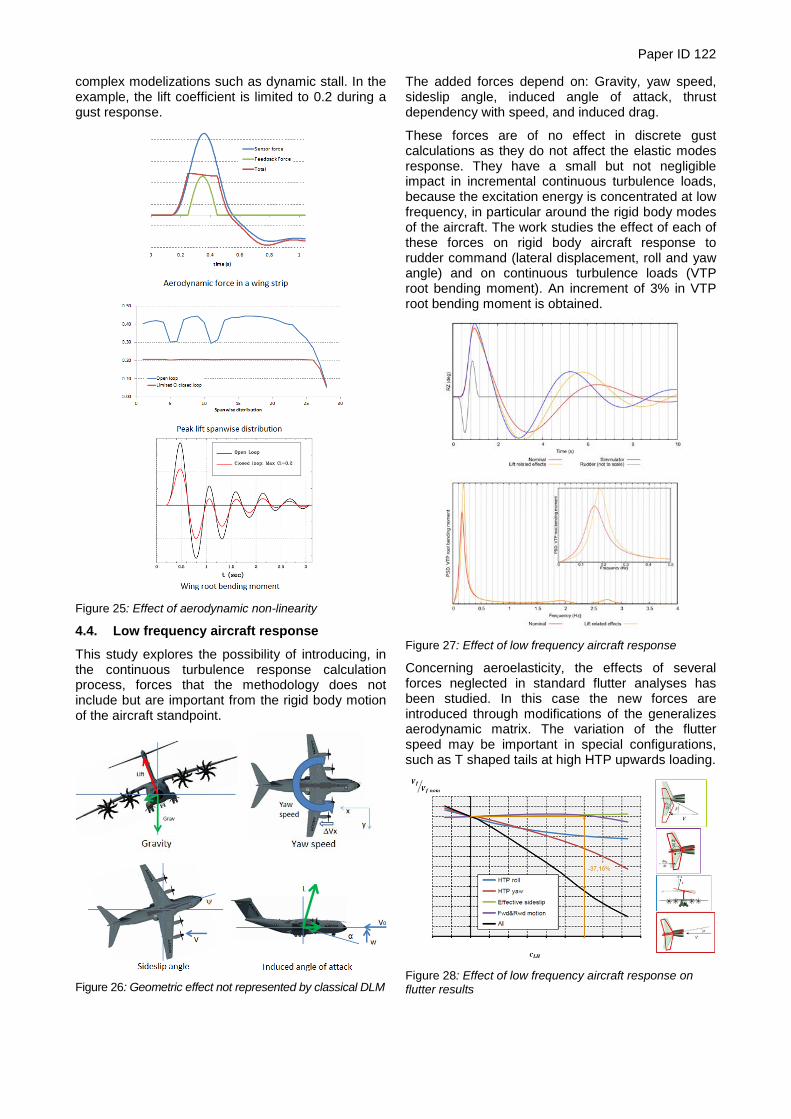
4.4. Low frequency aircraft response
This study explores the possibility of introducing, in the continuous turbulence response calculation process, forces that the methodology does not include but are important from the rigid body motion of the aircraft standpoint.
Figure 26: Geometric effect not represented by classical DLM
The added forces depend on: Gravity, yaw speed, sideslip angle, induced angle of attack, thrust dependency with speed, and induced drag.
These forces are of no effect in discrete gust calculations as they do not affect the elastic modes response. They have a small but not negligible impact in incremental continuous turbulence loads, because the excitation energy is concentrated at low frequency, in particular around the rigid body modes of the aircraft. The work studies the effect of each of these forces on rigid body aircraft response to rudder command (lateral displacement, roll and yaw angle) and on continuous turbulence loads (VTP root bending moment). An increment of 3% in VTP root bending moment is obtained.
Figure 27: Effect of low frequency aircraft response
Concerning aeroelasticity, the effects of several forces neglected in standard flutter analyses has been studied. In this case the new forces are introduced through modifications of the generalizes aerodynamic matrix. The variation of the flutter speed may be important in special configurations, such as T shaped tails at high HTP upwards loading.
Figure 28: Effect of low frequency aircraft response on flutter results
Paper ID 122
5. ASSESSMENT OF LOAD CONTROL CONCEPTS WITH RESPECT TO FATIGUE
The development of load control (LC) technology within the “Adaptive Wing” work package of SFWA is driven by the requirements of drag- and mass-reduction for future fixed-wing passenger aircraft. Two main concepts are investigated within the work package. These are “passive” and “active” LC tech-nologies. In this context, passive LC is thought to be achieved via aeroelastic tailoring of the wing’s struc-ture while active LC may involve existing or addi-tional movables (fast or slow moving) to influence the airflow in order to achieve more advantageous deformation (w.r.t. drag) and/or load-distribution (creating the potential for weight reduction in certain structural components).
Assessment Criteria
The present investigations focus on a methodology for the evaluation of LC concepts with respect to their potential for a reduction of structural weight. LC systems can only create a potential for weight reduc-tion, if their own weight is offset by enabling a weight-reduction in the structural parts of the aircraft.
If the implementation of LC concepts leads to less severe loading of structural components whose mass should or cannot be reduced, the benefit of the LC concept could alternatively be formulated e.g. in terms of longer maintenance intervals and a result-ing reduction in operating costs.
Assessment Methodology
The purpose of LC concepts is to change the inter-action of the aircraft with the airflow. It is therefore liable to change many aspects of a/c loading from the overall flight mechanics to the distribution of loads or stresses among structural members. This holds true for active as well as passive LC.
To assess the overall potential for weight reduction available through the implementation of LC concepts it is therefore necessary to use computational meth-ods modelling these mutually interactive effects. Furthermore, the level of detail of the analyses needs to be adaptable to the stage of a/c-design they are used for.
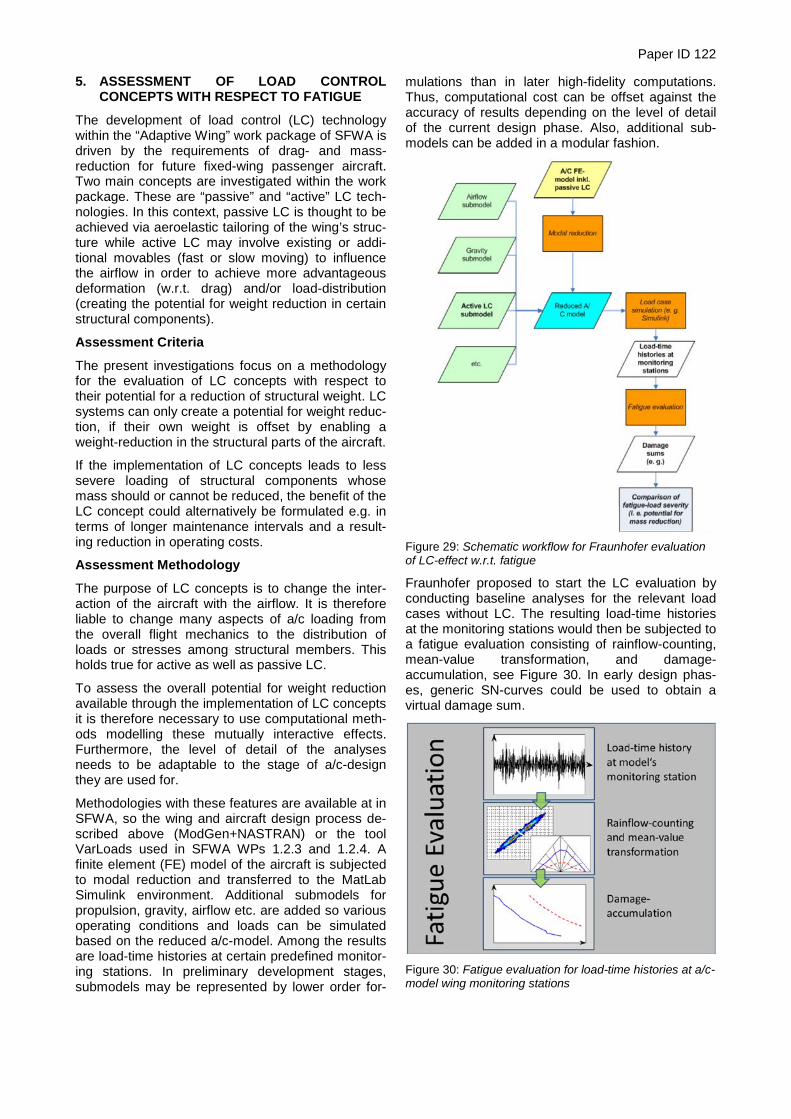
Methodologies with these features are available at in SFWA, so the wing and aircraft design process de-scribed above (ModGen+NASTRAN) or the tool VarLoads used in SFWA WPs 1.2.3 and 1.2.4. A finite element (FE) model of the aircraft is subjected to modal reduction and transferred to the MatLab Simulink environment. Additional submodels for propulsion, gravity, airflow etc. are added so various operating conditions and loads can be simulated based on the reduced a/c-model. Among the results are load-time histories at certain predefined monitor-ing stations. In preliminary development stages, submodels may be represented by lower order for-
mulations than in later high-fidelity computations. Thus, computational cost can be offset against the accuracy of results depending on the level of detail of the current design phase. Also, additional sub-models can be added in a modular fashion.
Figure 29: Schematic workflow for Fraunhofer evaluation of LC-effect w.r.t. fatigue
Fraunhofer proposed to start the LC evaluation by conducting baseline analyses for the relevant load cases without LC. The resulting load-time histories at the monitoring stations would then be subjected to a fatigue evaluation consisting of rainflow-counting, mean-value transformation, and damage-accumulation, see Figure 30. In early design phas-es, generic SN-curves could be used to obtain a virtual damage sum.
Figure 30: Fatigue evaluation for load-time histories at a/c-model wing monitoring stations

Paper ID 122
In a second step, the LC concept would be incorpo-rated into the a/c-model. In case of passive LC (aeroelastic tailoring), the FE-model would be modi-fied accordingly before being subjected to modal reduction. Aerodynamic simulations would then be used to modify the airflow submodel as well. The analysis would then proceed as before. Active LC systems would result in an additional submodel in-cluding their actuators and control laws. Additional aerodynamic simulations could be used to incorpo-rate the aerodynamic effect of the LC-system into the airflow-submodel or a separate submodel. In any case, the load-time histories at the monitoring sta-tions would be obtained for the relevant load cases as before and then subjected to the fatigue evalua-tion mentioned above. A comparison between the virtual damage sums with and without LC would then be used to evaluate the effect of the LC concept. Depending on the level of detail, this could even be expressed in a compari-son of preliminary weights of structural members. The approach presented here is documented in [9]. The work performed on the NSR aircraft (see Sec-tion 2.8) was performed by DLR on the basis of this approach. 6. ACKNOWLEDGEMENTS The authors would like to thank the Clean Sky Joint Undertaking and the European Union for the support of SFWA-ITD which has been funded within the scope of the Seventh Framework Programme for Research and Technology by the European Com-mission through the Grant Agreement CSJU-GAM-SFWA-2008-001. 7. LITERATURE [1] Dillinger, J.K.S., Abdalla, M.M., Klimmek, T. &
Gurdal, Z. (2012): Stiffness Optimization of Composite Wings with Aeroelastic Constraints. Proc. 12th AIAA Aviation Technology, Integra-tion, and Operations (ATIO) Conference and 14th AIAA/ISSMO Multidisciplinary Analysis and Optimization Conference Online Proceedings (2012) (pp. 1-15). Indianapolis.
[2] De Breuker, R., Abdalla, M.M., Werter, N.P.M., Vandewaeter, L., Ferede, E.A., Dillinger, J.K.S. & Krüger, W.R. (2013): An Aeroelastic Multi-Fidelity Approach for Aeroelastic Tailoring. Proc. International Forum on Aeroelasticity and Struc-tural Dynamics, IFASD 2013. London.
[3] Werter, N.P.M., De Breuker, R. (2012): Design of a composite forward swept wing using advanced aeroelastic tailoring optimisation methods. Morris, A., Gurdal, Z. (Eds.). Proc. RAeS 3rd Aircraft Structural Design Conference. London.
[4] Klimmek, T. (2009): Parameterization of topolo-gy and geometry for the multidisciplinary optimi-zation of wing structures. In: Proceedings "CEAS 2009". CEAS 2009 - European Air and Space Conference, 26-29 October 2009, Man-
chester, United Kingdom. [5] Dillinger, J., Klimmek, T., Abdalla, M.M. and
Gürdal, Z. (2013): Stiffness Optimization of Composite Wings with Aeroelastic Constraints. J. Aircraft, 50 (4), pp. 1159-1168. AIAA. ISSN 0021-8669.
[6] Dillinger, J.K.S. (2014): Static Aeroelastic Opti-mization of Composite Wings with Variable Stiff-ness Laminates, Dissertation, Delft, The Nether-lands, 2014. (Wohrmann Print Service) Prom/ coprom: Prof.dr. Z Gurdal & Dr. MM Abdalla.
[7] Krüger, W.R., Klimmek, T., Liepelt, R., Schmidt, H., Waitz, S. and Cumnuantip, S. (2014): Design and Aeroelastic Assessment of a Forward Swept Wing Aircraft. CEAS Aeronautical Journal, 5 (4), pp. 419 - 433.
[8] Karpel, M., Romm, A., Climent, H., Reyes, M. (2015): “Aircraft Dynamic Loads with Varying Geometry and Flight Mechanics Effects”. Proc. International Forum on Aeroelasticity and Struc-tural Dynamics, IFASD 2015, 28 June - 02 July, 2015, St. Petersburg, Russia.
[9] Kraus, K., Mayer, D., Herold S., Büter, A. (2012): Online Processing for Structural Health Assess-ment. 13th Mechatronics Forum International Conference. Linz, Austria, September 17-19.
[10] Dillinger, J., Abdalla, M.M., Klimmek, T., Gürdal, Z. (2013): Static Aeroelastic Stiffness Optimiza-tion and Investigation of Forward Swept Compo-site Wings. 10th World Congress on Structural and Multidisciplinary Optimization, 19-24 May 2013, Orlando, Florida, USA.
[11] Dillinger, J., Abdalla, M.M., Meddaikar, Y.M., Klimmek, T. (2015): Static Aeroelastic Stiffness Optimization of a Forward Swept Composite Wing with CFD Corrected Aero Loads. Proc. In-ternational Forum on Aeroelasticity and Struc-tural Dynamics, IFASD 2015, 28 June - 02 July, 2015, St. Petersburg, Russia.
[12] Meddaikar, Y.M., Irisarri, F.-X., Abdalla, M.M. (2015): Blended Composite Optimization com-bining Stacking Sequence Tables and a Modi-fied Shepard’s Method. 11th World Conference on Structural and Multidisciplinary Optimization, 7-12 Jun 2015, Sydney, Australia.
[13] Jovanov, K., De Breuker, R., Abdalla, M.M., Dillinger, J. (2015): Accelerated convergence of static aeroelasticity using low-fidelity aerody-namics. 56th AIAA/ASCE/AHS/ASC Structures, Structural Dynamics, and Materials Conference, 5-9 Jan 2015, Kissimmee, Florida, USA.
[14] Tischler, V., V. Venkayya, F. Eastep und G. Bharatram (1996): Design Interfaces and Data Transfer Issues in Multidisciplinary Design. In: Proc. of 6th AIAA/NASA/ISSMO Symposium on Multidisciplinary Analysis and Optimization, Nr. AIAA-96-4125-CP, S. 1212–1222, Bellevue, WA (USA), Sep. 4-6 1996. AIAA.


![SKRIPSI P2repository.its.ac.id/72928/2/4213105022-Presentation.pdf · [11]Gunawan M., G., Adetama. 2014 “Studi Eksperimental Mekanisme Passive-Pitch Dengan Flapping Wing Pada Turbin](https://img.dokumen.tips/doc/110x75/607f5019c5d5d666c57ea889/skripsi-11gunawan-m-g-adetama-2014-aoestudi-eksperimental-mekanisme-passive-pitch.jpg)