Embed Size (px)
Citation preview
Adaptive Control of Pantograph-Catenary Interaction Force
RUSU-ANGHEL STELA1- IEEE Member, CRISTINA MIKLOS2 and IULIAN-CIPRIAN LIHACIU3
Department of IEII1 Department of IM2
Student3 Politehnica University of Timisoara
Hunedoara, str. Revolutiei, nr. 5 ROMANIA
{stela.anghel, cristina.miklos }@fih.upt.ro, [email protected] http://www.fih.upt.ro Abstract: - The catenary and the pantograph of an electric locomotive have a dynamic-oscillatory behavior, to which are added a series of turbulences that cannot be approached by a classic calculation method. Experimental observations and reference literature point out the fact that at speeds higher than 180 km/h, the pantograph and the catenary temporarily lose contact and that triggers electric arcs with negative consequences. Some mathematical models have been developed, predicting the dynamic behavior of this assembly and of the contact force, but all of them have some degree of imprecision (disregarding the phenomena difficult to model). They also can not be used in real time to control the contact force between the pantograph and catenary. This paper suggests a new method thereby the system that controls the contact force is divided into two sub-systems: a determinative one and a chaotic one; for each one, appropriate adjustment laws are suggested. The solutions resulting from simulation are encouraging and need industrial implementation. Key-Words: - Pantograph, Contact force, Control, Chaos Theory, Adaptive, Fuzzy 1 Introduction The power supply of trains is made through the interface pantograph - catenary, which is currently the only system that allows the capture of electricity at important speeds in conditions of maximum reliability. In spite of the progress in the catenary conception, and the numerous maintenance works made periodically, this is a weak point of the rail transportation. After the breakage of the contact wire due to premature wear, electric arcs are getting out of gage and damage the pantograph, the locomotive cover and damages some more kilometers of rail until the train stops. Therefore, it leads to a strong disruption of traffic, measured in minutes lost, each being estimated at about €600. [1]
With over one million minutes lost every year across Europe, the overall cost of all incidents is considerably high.
Although simple in appearance, the coupling of the elastic catenary with a mobile pantograph that has its own dynamic behavior implies complex phenomena. [2] At pantograph speeds close to the wave propagation speed in the catenary, an instability appears, which leads to loss of contact. At lower speeds, when using more pantographs in simultaneous contact, the behavior is complex and
difficult to be mathematically modeled. In case of two lifted pantographs, the disturbances caused by the first one are transmitted to the second one, which is strongly disturbed (electric arcs, contact losses, mechanical shocks). The waves generated by the mobile contact are propagated in the entire structure, and combine themselves to produce very complex movements.
A major problem in the quality of the contact between the pantograph and the line is represented by the control of the interaction force between the two subsystems. This force contains a constant component, given by the lifting mechanism of the pantograph, and a variable component that depends on the totally different dynamic behavior of the pantograph and the catenary, respectively. If this dynamic behavior can be estimated through mathematical modeling, many factors that cannot be taken into account still remain. Also, the mathematical model cannot be used in real time, due to its complexity and long calculation time.
As it will be seen below, the contact force varies depending on the speed of the pantograph. So, at speeds exceeding 160 km/h, this force has moments when it becomes zero, which indicates the discontinuation of the electric contact, with
WSEAS TRANSACTIONS on SYSTEMS Rusu-Anghel Stela, Cristina Miklos, Iulian-Ciprian Lihaciu
E-ISSN: 2224-2678 708 Volume 13, 2014
predictable consequences (electric arc, mechanical shocks, etc.). To avoid this situation, the so-called "active control" of the pantograph appeared. In reference literature, there are many references to this topic, especially for speeds above 350 km/h.
In [1], J. P. Masat studies the issue of modeling the dynamic behavior of the couple pantograph-catenary by classic and advanced methods (the method of the finite element), and a comparison between the results of modeling and the experimental ones shows that there are slight differences between them. The models are complex and can be used for an optimal design of the catenary.
M. Ikeda [3] suggests an accurate method for gauging in real time the contact force. This method is already applied in Japan and it allows the obtaining of an accurate reaction loop.
P. Bandi [4] suggests a pantograph control system design for high speed rails, based on the theory of estate control. The paper is based on a simplified mathematical model for the catenary-pantograph assembly, but the results obtained by simulation have not been checked in practice.
Karakose [5] suggests an adaptive fuzzy control system for dynamic pantograph-catenary interaction. This model was designed by using the Matlab-Simulink program and simulation results were obtained.
The same aspect is approached in the papers [6], [9]. The system suggested here is simpler and more easily applicable in practice.
R. Schar [7] analyzes the active control of the pantograph-catenary interaction in a finite element model; the model is complex, with good experimental results, but it cannot be used for the real time control of the pantograph.
A Matvejevs [8] uses a computer of high speed train to optimize the pantograph-catenary system by reducing power consumption when basic parameters of pantograph and catenary (contact network) change over time randomly.
A linear model of pantograph-catenary system is considered where the upper and lower blocks of pantograph and catenary are modeled using lumped masses, springs and shock absorbers.
The input and output system signals are measured when the train moves. These signals are processed by parametric identification algorithms to determine the current values of the system matrices. State matrices are used in Riccati equation to calculate controller coefficients. Adaptive controller provides dynamic stability of the system when its parameters change over time, and the system is subject to random external perturbations.
The essential problem of all active control systems shown in reference literature and existing in practice, irrespective of the method in use, consists in the fact that, generally, one cannot take into consideration the phenomena that are hard to model mathematically, the random ones and those that are due to external factors (e.g. the vibrations of the engine case).
For this reason, this paper suggests a double control method: a classic one, for the mathematical modellable phenomena, and another one, based on the chaos theory, for the rest of the phenomena. For the control of the chaos, the Piragas time delayed control method was used [10], [11], as well as a fuzzy system for the adaptive determination of the amplification factor and the delay time. This approach represents a novelty in this domain, as there is no bibliographic reference to it. As it will be noticed, applying the chaos theory in stabilizing the contact force can lead to promising results.
In order to apply the method proposed, the actual drive system of the pantograph is kept, and it will be controlled using the analysis of the mathematical model of low frequencies. This was proved to be less influenced by random factors that cannot be modeled, and it describes correctly the pantograph-catenary ensemble.
The random and hard to model phenomena are present at higher frequencies in the representation of the real contact force, and can be mathematically proven that they have a chaotic behavior. To diminish their influence, the chaotic-control system will drive only the pan head of the pantograph, by applying the necessary corrections. The pan head weights very little (a few kilograms), and it is attached by the structure of the pantograph using shock absorbers.
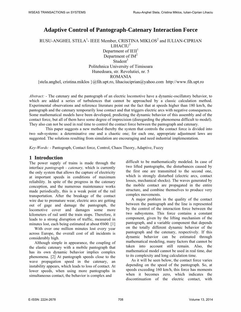
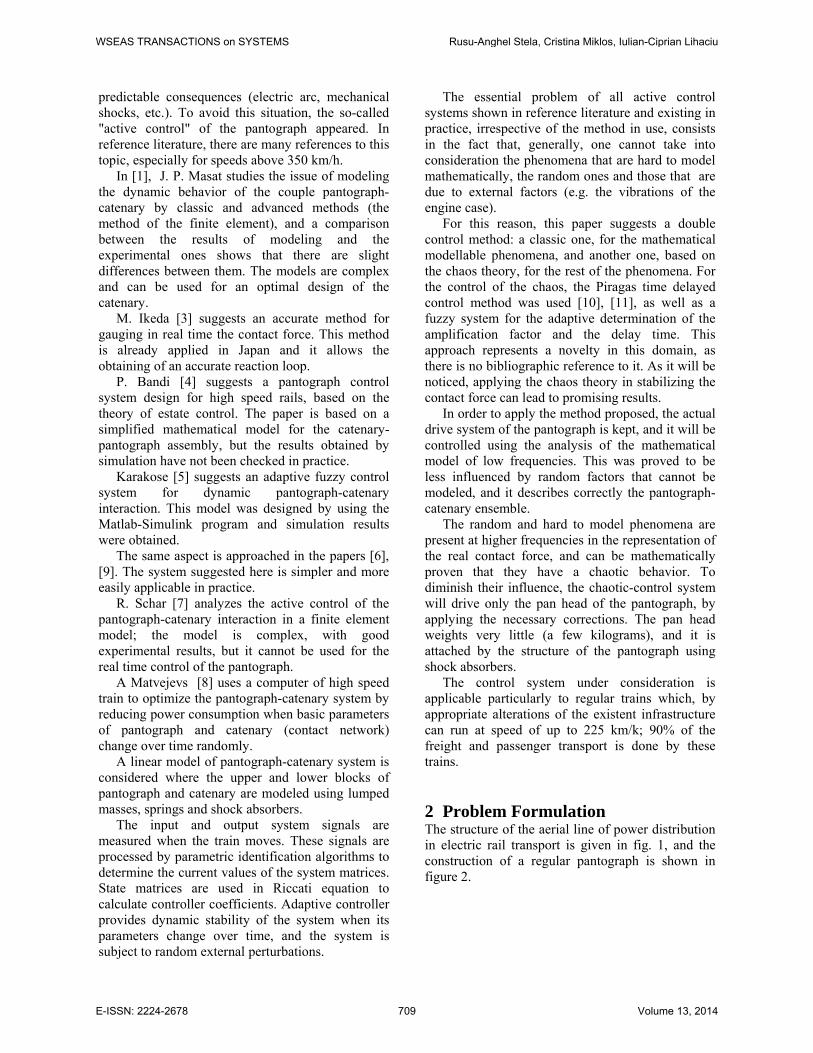
The control system under consideration is applicable particularly to regular trains which, by appropriate alterations of the existent infrastructure can run at speed of up to 225 km/k; 90% of the freight and passenger transport is done by these trains. 2 Problem Formulation The structure of the aerial line of power distribution in electric rail transport is given in fig. 1, and the construction of a regular pantograph is shown in figure 2.
WSEAS TRANSACTIONS on SYSTEMS Rusu-Anghel Stela, Cristina Miklos, Iulian-Ciprian Lihaciu
E-ISSN: 2224-2678 709 Volume 13, 2014
The phenomenological aspects of the dynamic behavior of the catenary-pantograph assembly show that the linear movement of the pantograph is also accompanied by a harmonic-oscillatory movement of the contact wire, and by a permanent oscillatory movement of the pan-head. The flexibility of the catenary allows the pan head pressure force to overcome the elastic force, as well as the effect of the equivalent of the system inertial mass, lifting the contact line.
Once the pantograph has passed, the weight of
the contact line tends to return it to the balance state, thus performing a harmonic-oscillatory movement whose waves are transmitted along the catenary. On the other hand, the rigidity variation of the entire suspension assembly determines an approximately sinusoidal vertical variation of the pan-head position. The composition of the two movements can lead to dynamic phenomena which, in extreme cases, prevent the pan-head from following the oscillations of the contact line. In such situations, the pan-head is bound to detach from the contact line, the contact is interrupted and electric arcs may arise, which implies negative effects like the wear of
the contact line, electromagnetic pollution, etc. The analysis of the phenomena happening during the movement of the pantograph along the catenary leads to the conclusion that, from the kinetic-static and dynamic point of view, the coupling of the two elastic sub-systems results exclusively from the contact force: when the pantograph is in contact with the catenary wire, the movement of the components located in the upper area of the pan-head and the lower wire of the catenary are identical and the value of the contact force is different from zero, it being generated by the reciprocal mechanical force. When the pantograph loses contact with the catenary wire, the contact force becomes null and the positions of the pantograph and catenary are independent.
It is generally accepted that the catenary-pantograph assembly represents the critical component of the traction system, particularly in the actual situation of a higher speed of trains because:
- the catenary and the pantograph form an oscillatory system whose elements are dynamically coupled, and excited by the contact force;
- the pantograph introduces non-linear characteristics in the functioning of the oscillatory system, generating non-linearities in the manifestation of the dynamic phenomenon;
- the dynamic response of the system is influenced both by the rigidity characteristics of the components and the degrees of liberty of the generally articulated connections, as well as by the geometric structure of the assembly;
- the higher the speed, the more serious are the problems of dynamic interaction, which shows that, from the point of view of the dynamic behavior, the rigidity of the ideal catenary must be as even as possible, this element requiring particular geometric configurations for the high speed train traffic; because of the catenary rigidity variation, an excessive increase of the contact force can cause significant distortions in the movement of the catenary, which leads to even higher dynamic excitations, whose effect is the contact braking particularly in the more rigid zones of the catenary. But if the pressing force is too low, even slight distortions can cause contact breaks, which cause not only an interruption of the power supply but also an electric arc that can severely damage the catenary and pantograph, significantly reducing their active life.
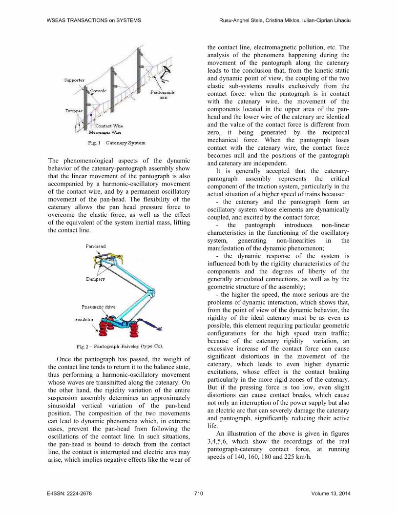
An illustration of the above is given in figures 3,4,5,6, which show the recordings of the real pantograph-catenary contact force, at running speeds of 140, 160, 180 and 225 km/h.
WSEAS TRANSACTIONS on SYSTEMS Rusu-Anghel Stela, Cristina Miklos, Iulian-Ciprian Lihaciu
E-ISSN: 2224-2678 710 Volume 13, 2014
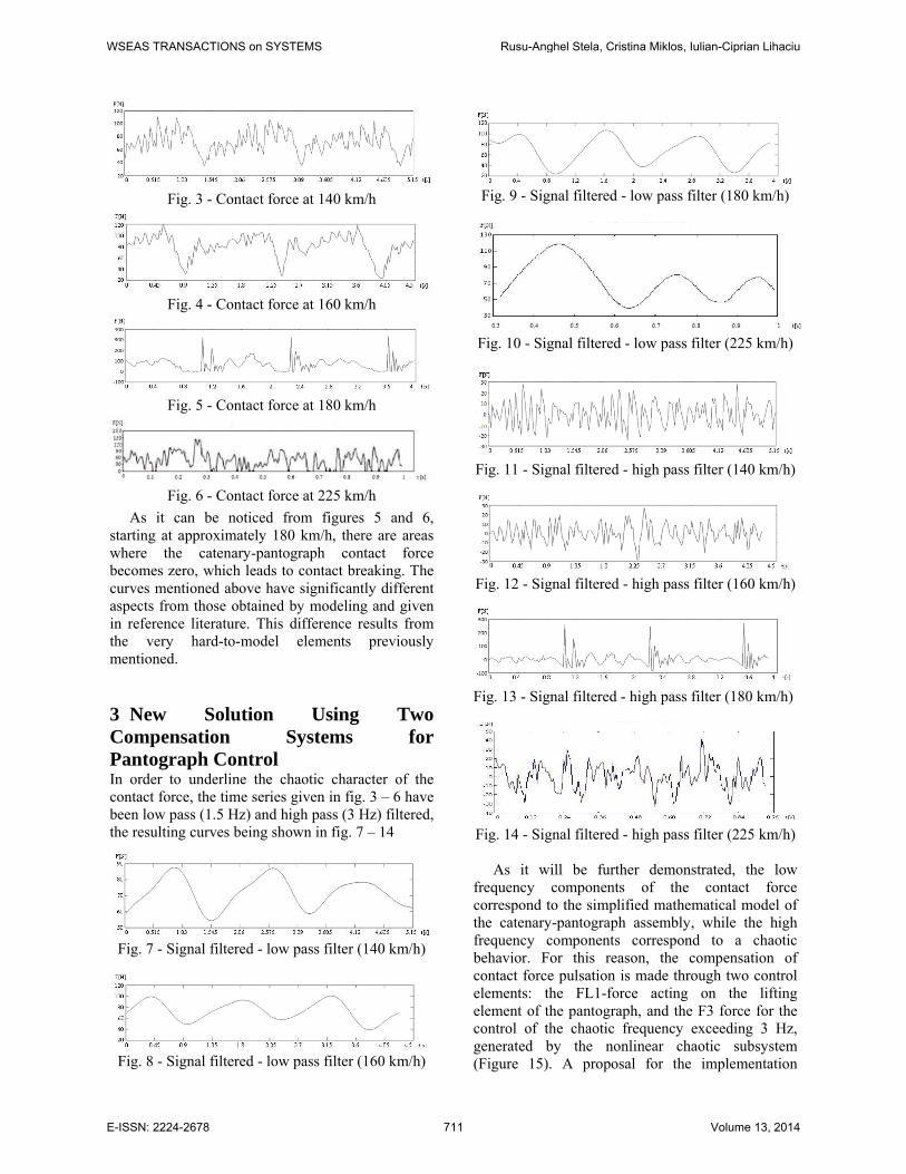
Fig. 3 - Contact force at 140 km/h
Fig. 4 - Contact force at 160 km/h
Fig. 5 - Contact force at 180 km/h
Fig. 6 - Contact force at 225 km/h
As it can be noticed from figures 5 and 6, starting at approximately 180 km/h, there are areas where the catenary-pantograph contact force becomes zero, which leads to contact breaking. The curves mentioned above have significantly different aspects from those obtained by modeling and given in reference literature. This difference results from the very hard-to-model elements previously mentioned.
3 New Solution Using Two Compensation Systems for Pantograph Control In order to underline the chaotic character of the contact force, the time series given in fig. 3 – 6 have been low pass (1.5 Hz) and high pass (3 Hz) filtered, the resulting curves being shown in fig. 7 – 14
Fig. 7 - Signal filtered - low pass filter (140 km/h)
Fig. 8 - Signal filtered - low pass filter (160 km/h)
Fig. 9 - Signal filtered - low pass filter (180 km/h)
Fig. 10 - Signal filtered - low pass filter (225 km/h)
Fig. 11 - Signal filtered - high pass filter (140 km/h)
Fig. 12 - Signal filtered - high pass filter (160 km/h)
Fig. 13 - Signal filtered - high pass filter (180 km/h)
Fig. 14 - Signal filtered - high pass filter (225 km/h)
As it will be further demonstrated, the low frequency components of the contact force correspond to the simplified mathematical model of the catenary-pantograph assembly, while the high frequency components correspond to a chaotic behavior. For this reason, the compensation of contact force pulsation is made through two control elements: the FL1-force acting on the lifting element of the pantograph, and the F3 force for the control of the chaotic frequency exceeding 3 Hz, generated by the nonlinear chaotic subsystem (Figure 15). A proposal for the implementation
WSEAS TRANSACTIONS on SYSTEMS Rusu-Anghel Stela, Cristina Miklos, Iulian-Ciprian Lihaciu
E-ISSN: 2224-2678 711 Volume 13, 2014
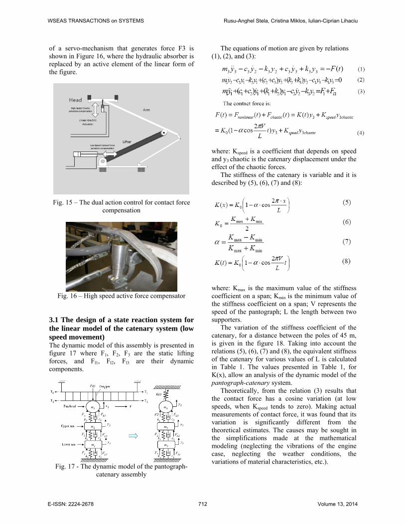
of a servo-mechanism that generates force F3 is shown in Figure 16, where the hydraulic absorber is replaced by an active element of the linear form of the figure.
Fig. 15 – The dual action control for contact force
compensation
Fig. 16 – High speed active force compensator
3.1 The design of a state reaction system for the linear model of the catenary system (low speed movement) The dynamic model of this assembly is presented in figure 17 where F1, F2, F3 are the static lifting forces, and Fl1, Fl2, Fl3 are their dynamic components.
Fig. 17 - The dynamic model of the pantograph-
catenary assembly
The equations of motion are given by relations (1), (2), and (3):
where: Kspeed is a coefficient that depends on speed and y3 chaotic is the catenary displacement under the effect of the chaotic forces.
The stiffness of the catenary is variable and it is described by (5), (6), (7) and (8):
where: Kmax is the maximum value of the stiffness coefficient on a span; Kmin is the minimum value of the stiffness coefficient on a span; V represents the speed of the pantograph; L the length between two supporters.
The variation of the stiffness coefficient of the catenary, for a distance between the poles of 45 m, is given in the figure 18. Taking into account the relations (5), (6), (7) and (8), the equivalent stiffness of the catenary for various values of L is calculated in Table 1. The values presented in Table 1, for K(x), allow an analysis of the dynamic model of the pantograph-catenary system.
Theoretically, from the relation (3) results that the contact force has a cosine variation (at low speeds, when Kspeed tends to zero). Making actual measurements of contact force, it was found that its variation is significantly different from the theoretical estimates. The causes may be sought in the simplifications made at the mathematical modeling (neglecting the vibrations of the engine case, neglecting the weather conditions, the variations of material characteristics, etc.).
WSEAS TRANSACTIONS on SYSTEMS Rusu-Anghel Stela, Cristina Miklos, Iulian-Ciprian Lihaciu
E-ISSN: 2224-2678 712 Volume 13, 2014
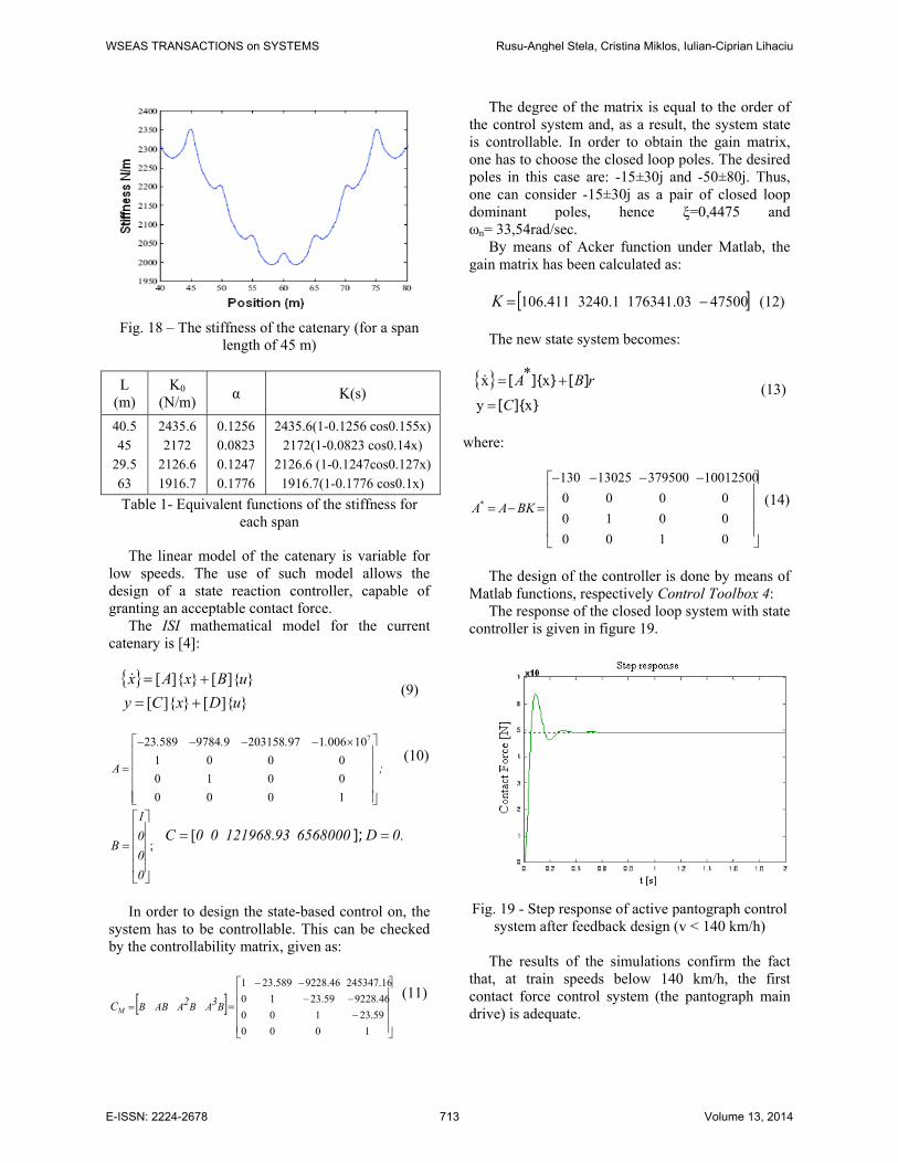
Fig. 18 – The stiffness of the catenary (for a span
length of 45 m)
L (m)
K0 (N/m) α K(s)
40.5 45
29.5 63
2435.6 2172
2126.6 1916.7
0.1256 0.0823 0.1247 0.1776
2435.6(1-0.1256 cos0.155x) 2172(1-0.0823 cos0.14x)
2126.6 (1-0.1247cos0.127x) 1916.7(1-0.1776 cos0.1x)
Table 1- Equivalent functions of the stiffness for each span
The linear model of the catenary is variable for low speeds. The use of such model allows the design of a state reaction controller, capable of granting an acceptable contact force.
The ISI mathematical model for the current catenary is [4]:
{ }
}]{[}]{[}]{[}]{[
uDxCyuBxAx
+=+=&
(9)
723 589 9784 9 203158 97 1 006 10
1 0 0 00 1 0 00 0 0 1
. . . .
A ;
⎡ ⎤− − − − ×⎢ ⎥⎢ ⎥=⎢ ⎥⎢ ⎥⎢ ⎥⎣ ⎦
(10)
;
⎥⎥⎥⎥
⎦
⎤
⎢⎢⎢⎢
⎣
⎡
=
0001
B .0D65680009312196800C == ]; .[
In order to design the state-based control on, the system has to be controllable. This can be checked by the controllability matrix, given as:
[ ]⎥⎥⎥⎥
⎦
⎤
⎢⎢⎢⎢
⎣
⎡
=−−−
−−
=
100023.59100
9228.4623.5910245347.169228.4623.5891
B3AB2AABBMC (11)
The degree of the matrix is equal to the order of the control system and, as a result, the system state is controllable. In order to obtain the gain matrix, one has to choose the closed loop poles. The desired poles in this case are: -15±30j and -50±80j. Thus, one can consider -15±30j as a pair of closed loop dominant poles, hence ξ=0,4475 and ωn= 33,54rad/sec.
By means of Acker function under Matlab, the gain matrix has been calculated as:
[ ]47500176341.033240.1106.411 −=K (12)
The new state system becomes:
{ }}]{[
][}]{[xy
x*xC
rBA=
+=& (13)
where:
⎥⎥⎥⎥
⎦
⎤
⎢⎢⎢⎢
⎣
⎡ −−−−
=−=
010000100000
1001250037950013025130
* BKAA (14)
The design of the controller is done by means of Matlab functions, respectively Control Toolbox 4:
The response of the closed loop system with state controller is given in figure 19.
Fig. 19 - Step response of active pantograph control
system after feedback design (v < 140 km/h)
The results of the simulations confirm the fact that, at train speeds below 140 km/h, the first contact force control system (the pantograph main drive) is adequate.
WSEAS TRANSACTIONS on SYSTEMS Rusu-Anghel Stela, Cristina Miklos, Iulian-Ciprian Lihaciu
E-ISSN: 2224-2678 713 Volume 13, 2014
3.1 The compensation of oscillations at high speeds, by means of an adaptive “time delay feedback” controller In order to define the chaotic character of the signals given in figures 11, 12, 13, 14 they are going to be thoroughly analyzed.
3.2.1 The chaotic characteristics of the contact force As a rule, in an experiment one measures just a few physical magnitudes, which are characteristic for the given process, sometimes even just one. The values taken by this magnitude in time constitute the so-called time series. Starting from the time series of the values of one state variable, i.e. one component of the state vector, one can reconstruct the entire phase space, identifying the attractor and assess its dimension. The method is called “The delay coordinates” [12], [13].
The basic idea in reconstructing the phase space is that the time series contains the entire information about the past and future of the state variables, including the non-observable ones, of the dynamic system and that this information can be used to define the state of this system at the present moment. Thus, one can check if the system intricate dynamics is a determined or a stochastic one or (and) if the system has an attractor and, if so, what is its dimension and, finally, which is the minimal dimension of the phase space in which the attractor is embedded.
The past and future information contained included by the time series is described by the late vector. Thus, of the scalar time series is given by the values of x0(t), (of the xk(t) possible, with k=0,1,2,...m), the first step is to identify the acceptable set of variables that determine the phase space.
One way of doing this is to “dismantle” the original time series ( )tx0 by shifts, i.e. time translations, successively larger, defined as integer multiples of a determined interval τ . This interval is tΔ= ατ , where α is an integer, and tΔ is the interval between successive samplings. Taking N equidistant points from the data set, one can build the next vector set, which can be set into a matrix as follows:
( ) ( ) ( )
( ) ( ) ( )( ) ( ) ( )
( )( ) ( )( )
1 20 0 0
1 20 0 0
1 20 0 0
10 0
2 2 2
1 1
N
N
N
N
x t x t x t
x t x t x t
x t x t x t
x t m x t m
τ τ τ
τ τ τ
τ τ
⎛ ⎞⋅ ⋅ ⋅⎜ ⎟
+ + ⋅ ⋅ ⋅ +⎜ ⎟⎜ ⎟+ + ⋅ ⋅ ⋅ +⎜ ⎟⎜ ⎟⋅ ⋅ ⋅ ⋅ ⋅ ⋅⎜ ⎟
⋅ ⋅ ⋅ ⋅ ⋅ ⋅⎜ ⎟⎜ ⎟⋅ ⋅ ⋅ ⋅ ⋅ ⋅⎜ ⎟⎜ ⎟⎡ ⎤ ⎡ ⎤+ − ⋅ ⋅ ⋅ ⋅ + −⎣ ⎦ ⎣ ⎦⎝ ⎠
(15)
This matrix is a collection of vectors, each having dimension m. Each vector, i.e. each column, is considered as representing the system at a given moment, and the evolution of the system state is given by the passage from one vector to another, i.e. from one column to another. Thus, on principle, this is a passage from the one-dimensional space of the time series to a multiple dimension space and this is expected to offer information about the dynamics of the system state. One can notice that in matrix (15) the important parameters are m andτ .
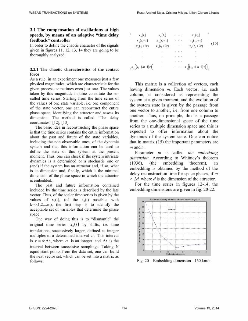
Parameter m is called the embedding dimension. According to Whitney’s theorem (1936), (the embedding theorem), an embedding is obtained by the method of the delay reconstruction time for space phases, if m > 2d, where d is the dimension of the attractor.
For the time series in figures 12-14, the embedding dimensions are given in fig. 20-22.
Fig. 20 – Embedding dimension - 160 km/h
WSEAS TRANSACTIONS on SYSTEMS Rusu-Anghel Stela, Cristina Miklos, Iulian-Ciprian Lihaciu
E-ISSN: 2224-2678 714 Volume 13, 2014
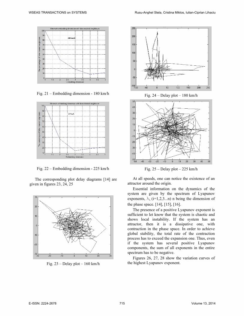
Fig. 21 – Embedding dimension - 180 km/h
Fig. 22 – Embedding dimension - 225 km/h
The corresponding plot delay diagrams [14] are given in figures 23, 24, 25
Fig. 23 – Delay plot – 160 km/h
Fig. 24 – Delay plot – 180 km/h
Fig. 25 – Delay plot – 225 km/h
At all speeds, one can notice the existence of an attractor around the origin.
Essential information on the dynamics of the system are given by the spectrum of Lyapunov exponents, li, (i=1,2,3...n) n being the dimension of the phase space. [14], [15], [16].
The presence of a positive Lyapunov exponent is sufficient to let know that the system is chaotic and shows local instability. If the system has an attractor, then it is a dissipative one, with contraction in the phase space. In order to achieve global stability, the total rate of the contraction process has to exceed the expansion one. Thus, even if the system has several positive Lyapunov components, the sum of all exponents in the entire spectrum has to be negative.
Figures 26, 27, 28 show the variation curves of the highest Lyapunov exponent.
WSEAS TRANSACTIONS on SYSTEMS Rusu-Anghel Stela, Cristina Miklos, Iulian-Ciprian Lihaciu
E-ISSN: 2224-2678 715 Volume 13, 2014
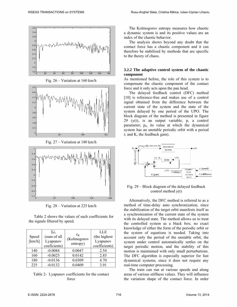
Fig. 26 – Variation at 160 km/h
Fig. 27 – Variation at 180 km/h
Fig. 28 – Variation at 225 km/h
Table 2 shows the values of such coefficients for
the signals filtered by speed.
Speed [km/h]
Σλi (sum of all Lyapunov
coeficients)
εK (Kolmogorov
entropy)
LLE (the highest Lyapunov
coefficients) 140 -0.0084 0.0047 2.54 160 -0.0025 0.0142 2.85 180 -0.0136 0.0309 4.70 225 -0.0132 0.0409 3.91
Table 2- Lyapunov coefficients for the contact force
The Kolmogorov entropy measures how chaotic a dynamic system is and its positive values are an index of the chaotic behavior.
The analysis shows beyond any doubt that the contact force has a chaotic component and it can therefore be stabilized by methods that are specific to the theory of chaos.
3.2.2 The adaptive control system of the chaotic component As mentioned before, the role of this system is to compensate the chaotic component of the contact force and it only acts upon the pan head.
The delayed feedback control (DFC) method [10] is reference-free and makes use of a control signal obtained from the difference between the current state of the system and the state of the system delayed by one period of the UPO. The block diagram of the method is presented in figure 29 (y(t), is an output variable; p, a control parameter; p0, its value at which the dynamical system has an unstable periodic orbit with a period t; and K, the feedback gain).
Fig. 29 – Block diagram of the delayed feedback
control method y(t) Alternatively, the DFC method is referred to as a
method of time-delay auto synchronization, since the stabilization of the target orbit manifests itself as a synchronization of the current state of the system with its delayed state. The method allows us to treat the controlled system as a black box; no exact knowledge of either the form of the periodic orbit or the system of equations is needed. Taking into account only the period of the unstable orbit, the system under control automatically settles on the target periodic motion, and the stability of this motion is maintained with only small perturbations. The DFC algorithm is especially superior for fast dynamical systems, since it does not require any real-time computer processing.
The train can run at various speeds and along areas of various stiffness values. They will influence the variation shape of the contact force. In order
WSEAS TRANSACTIONS on SYSTEMS Rusu-Anghel Stela, Cristina Miklos, Iulian-Ciprian Lihaciu
E-ISSN: 2224-2678 716 Volume 13, 2014
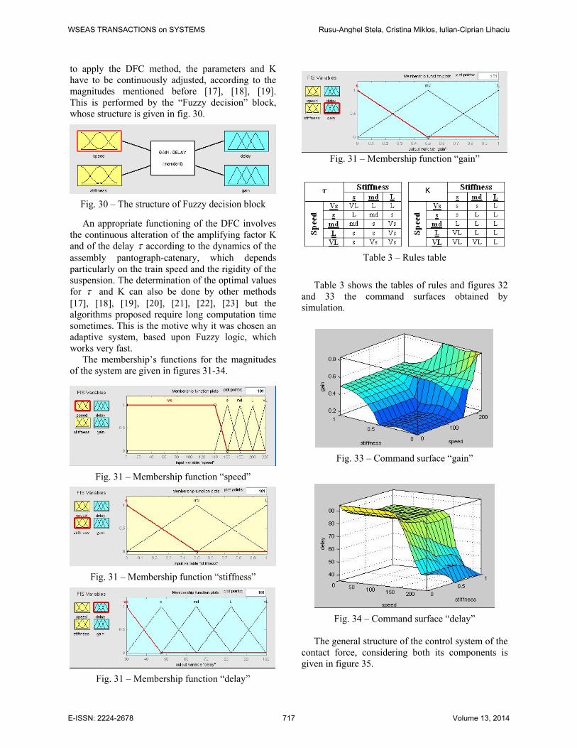
to apply the DFC method, the parameters and K have to be continuously adjusted, according to the magnitudes mentioned before [17], [18], [19]. This is performed by the “Fuzzy decision” block, whose structure is given in fig. 30.
Fig. 30 – The structure of Fuzzy decision block
An appropriate functioning of the DFC involves
the continuous alteration of the amplifying factor K and of the delay τ according to the dynamics of the assembly pantograph-catenary, which depends particularly on the train speed and the rigidity of the suspension. The determination of the optimal values for τ and K can also be done by other methods [17], [18], [19], [20], [21], [22], [23] but the algorithms proposed require long computation time sometimes. This is the motive why it was chosen an adaptive system, based upon Fuzzy logic, which works very fast.
The membership’s functions for the magnitudes of the system are given in figures 31-34.
Fig. 31 – Membership function “speed”
Fig. 31 – Membership function “stiffness”
Fig. 31 – Membership function “delay”
Fig. 31 – Membership function “gain”
Table 3 – Rules table
Table 3 shows the tables of rules and figures 32 and 33 the command surfaces obtained by simulation.
Fig. 33 – Command surface “gain”
Fig. 34 – Command surface “delay”
The general structure of the control system of the
contact force, considering both its components is given in figure 35.
WSEAS TRANSACTIONS on SYSTEMS Rusu-Anghel Stela, Cristina Miklos, Iulian-Ciprian Lihaciu
E-ISSN: 2224-2678 717 Volume 13, 2014
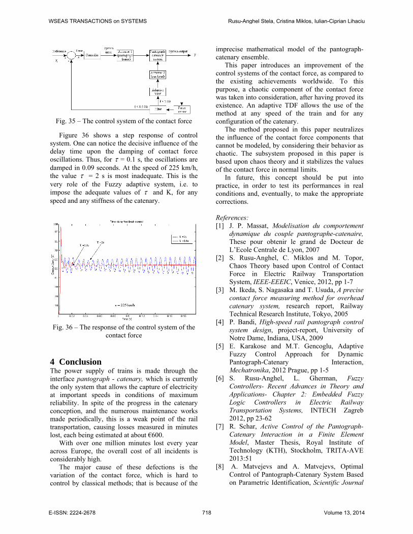
Fig. 35 – The control system of the contact force
Figure 36 shows a step response of control system. One can notice the decisive influence of the delay time upon the damping of contact force oscillations. Thus, for τ = 0.1 s, the oscillations are damped in 0.09 seconds. At the speed of 225 km/h, the value τ = 2 s is most inadequate. This is the very role of the Fuzzy adaptive system, i.e. to impose the adequate values of τ and K, for any speed and any stiffness of the catenary.
Fig. 36 – The response of the control system of the
contact force 4 Conclusion The power supply of trains is made through the interface pantograph - catenary, which is currently the only system that allows the capture of electricity at important speeds in conditions of maximum reliability. In spite of the progress in the catenary conception, and the numerous maintenance works made periodically, this is a weak point of the rail transportation, causing losses measured in minutes lost, each being estimated at about €600.
With over one million minutes lost every year across Europe, the overall cost of all incidents is considerably high.
The major cause of these defections is the variation of the contact force, which is hard to control by classical methods; that is because of the
imprecise mathematical model of the pantograph-catenary ensemble.
This paper introduces an improvement of the control systems of the contact force, as compared to the existing achievements worldwide. To this purpose, a chaotic component of the contact force was taken into consideration, after having proved its existence. An adaptive TDF allows the use of the method at any speed of the train and for any configuration of the catenary.
The method proposed in this paper neutralizes the influence of the contact force components that cannot be modeled, by considering their behavior as chaotic. The subsystem proposed in this paper is based upon chaos theory and it stabilizes the values of the contact force in normal limits.
In future, this concept should be put into practice, in order to test its performances in real conditions and, eventually, to make the appropriate corrections.
References: [1] J. P. Massat, Modelisation du comportement
dynamique du couple pantographe-catenaire, These pour obtenir le grand de Docteur de L’Ecole Centrale de Lyon, 2007
[2] S. Rusu-Anghel, C. Miklos and M. Topor, Chaos Theory based upon Control of Contact Force in Electric Railway Transportation System, IEEE-EEEIC, Venice, 2012, pp 1-7
[3] M. Ikeda, S. Nagasaka and T. Usuda, A precise contact force measuring method for overhead catenary system, research report, Railway Technical Research Institute, Tokyo, 2005
[4] P. Bandi, High-speed rail pantograph control system design, project-report, University of Notre Dame, Indiana, USA, 2009
[5] E. Karakose and M.T. Gencoglu, Adaptive Fuzzy Control Approach for Dynamic Pantograph-Catenary Interaction, Mechatronika, 2012 Prague, pp 1-5
[6] S. Rusu-Anghel, L. Gherman, Fuzzy Controllers- Recent Advances in Theory and Applications- Chapter 2: Embedded Fuzzy Logic Controllers in Electric Railway Transportation Systems, INTECH Zagreb 2012, pp 23-62
[7] R. Schar, Active Control of the Pantograph-Catenary Interaction in a Finite Element Model, Master Thesis, Royal Institute of Technology (KTH), Stockholm, TRITA-AVE 2013:51
[8] A. Matvejevs and A. Matvejevs, Optimal Control of Pantograph-Catenary System Based on Parametric Identification, Scientific Journal
WSEAS TRANSACTIONS on SYSTEMS Rusu-Anghel Stela, Cristina Miklos, Iulian-Ciprian Lihaciu
E-ISSN: 2224-2678 718 Volume 13, 2014
of Riga Technical University, Vol XLV, 2011, pp 17-23
[9] S. Rusu-Anghel, C. Panoiu, M. Panoiu and S. Mezinescu, Advanced System for the Control of Work Regime of Railway Electric Drive Equipement, 6TH WSEAS – EEESD Conference, Timisoara, Romania, 2010
[10] K. Pyragas, Delayed feedback control chaos, Phil. Trans. R. Soc. A, 2006, 364 pp 2309-2334
[11] K. Pyragas, Time-Delayed Feedback Control Method and Unstable Controllers, The European Physical Journal B, 2013, 86:306 pp 9-21
[12] T.D. Nguyen, T. T .D. Phan and R. Jasek, Parameter Estimation in Five Dimensions Chaotic Synchronization Systems by Self-Organizing Migrating Algorithm, WSEAS Transactions on Systems, VOL. XI, NO. XI, April 2012, pp 117-128
[13] V. Bobal, P. Chalupa, M. Kubalcik and P. Dostal, Identification and Self-tuning Control of Time-delay Systems, WSEAS Transactions on Systems, VOL. XI, NO. X, October 2012, pp 596-606
[14] E. Scholl and H. G. Schuster, Handbook of Chaos Control, WILEY-VCH Verlag GmbH, 2008
[15] K. Pyragas, Experimental control of chaos by delayed self-controlling feedback, Physics letters A, 180, 1993, pp 99-102
[16] P. Yu. Guzenko, J. Lehnert and E. Scholl, Application of Adaptive Methods to Chaos Control of Networks of Rossler Systems, Cybernetics and Physics, Vol. II, No. I, 2013, pp 15-24
[17] V. Pyragas and K. Pyragas, Adaptive search for the optimal feedback gain of time-delayed feedback controlled systems in the presence of noise, The European Physical Journal B, 2013, 86:306, pp 1-8
[18] V. Pyragas and K. Pyragas, Adaptive modification of the delayed feedback control algorithm with a continuously varying time delay, Physics letters A, A375, 2011, pp 3866-3871
[19] V. Pyragas and K. Pyragas, Adaptive delayed feedback control algorithm with a state dependent delay, proceedings of ENOC 2011, (Rome, Italy), pp 3868-3871
[20] L. Pekar and F. Neri, An Introduction to the Special Issue on Time Delay Systems: Modelling, Identification, Stability, Control and Applications, WSEAS Transactions on Systems, VOL. XI, NO. X, October 2012, pp 539-540
[21] M. R. Naseh and M. Haeri, An Adaptive Approach to Synchronization of Two Chua’s Circuits, WSEAS International Journal of Electrical, Electronic Science and Engineering, Vol. I, Nr. VI, 2007, pp 857-860
[22] R. Prokop, J. Korbel and R. Matusu, Autotuning Principles for Time-delay Systems, WSEAS Transactions on Systems, VOL. XI, NO. X, October 2012, pp 561-570
[23] P. Dostal, V. Bobal and Z. Babik, Control of Unstable and Integrating Time Delay Systems Using Time Delay Approximations, WSEAS Transactions on Systems, VOL. XI, NO. X, October 2012, pp 588-595
[24] C. Panoiu, M. Panoiu, L. Toma and R. Rob, A Real-Time Identification Method of Slow Process Parameters Using Adaptive IIR-OSLMS Filters, Wseas Transactions on Systems, Greece, ISSN 1109-2777, 2008, pp 1143-1154
[25] C. Panoiu, M. Panoiu, Modeling, Simulation and optimisation – Chapter: Using Adaptive filters in controlling of electrical resistance furnace temperature based on a real time identification method, InTech, Zagreb, 2013
[26] S. Basu and E. Foufoula-Georgiu, Detection of Nonlinearity and Chaoticity in Time Series Using the Transportation Distance Function, Physics Letters A, 301 September (2002), pp 413-423
[27] S. Rusu-Anghel, C. Miklos, M. Topor and D. Demian, Pantograph–Catenary System Control Using Elements of Chaos Theory, Pantograph Catenary Interaction Framework for Intelligent Control Conference 2011-IEEE France section, pp 73-85
[28] S. Staines A. and F. Neri, A Matrix Transition Oriented Net for Modeling Distributed Complex Computer and Communication Systems, WSEAS Transactions on Systems, 13, WSEAS Press (Athens, Greece), 2014, pp. 12-22.
[29] M. Camilleri, F. Neri and M. Papoutsidakis, An Algorithmic Approach to Parameter Selection in Machine Learning using Meta-Optimization Techniques, WSEAS Transactions on Systems, 13, WSEAS Press (Athens, Greece), 2014, pp. 202-213.
[30] M. Papoutsidakis, D. Piromalis, F. Neri and M. Camilleri, Intelligent Algorithms Based on Data Processing for Modular Robotic Vehicles Control, WSEAS Transactions on Systems, 13, WSEAS Press (Athens, Greece), 2014, pp. 242-251.
WSEAS TRANSACTIONS on SYSTEMS Rusu-Anghel Stela, Cristina Miklos, Iulian-Ciprian Lihaciu
E-ISSN: 2224-2678 719 Volume 13, 2014