Embed Size (px)
Citation preview
1
OVERFLOW Grid Adaption Training
Thomas H. Pulliam NASA Ames Research Center, Moffett Field, CA
Pieter G. Buning NASA Langley Research Center, Hampton, VA
13th Symposium on Overset Composite Grids and Solution Technology October 17-20, 2016, Mukilteo, WA
https://ntrs.nasa.gov/search.jsp?R=20170000221 2018-05-08T19:13:36+00:00Z
2
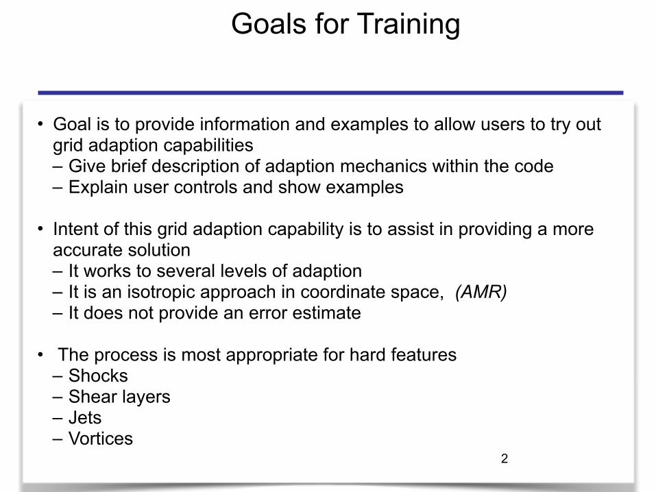
Goals for Training
• Goal is to provide information and examples to allow users to try out grid adaption capabilities – Give brief description of adaption mechanics within the code – Explain user controls and show examples
• Intent of this grid adaption capability is to assist in providing a more accurate solution – It works to several levels of adaption – It is an isotropic approach in coordinate space, (AMR) – It does not provide an error estimate
• The process is most appropriate for hard features – Shocks – Shear layers – Jets – Vortices

3
Naming Convention for Grid Levels
• Near-body (body-fitted curvilinear) grids are user-supplied – Original grids are “Level 0” – Refined grids are Level -1, -2, etc., each 2x finer than previous level
• Off-body (Cartesian) grids are automatically generated by the flow solver – Finest original grid is “Level 1,” with spacing set by input parameter DS – Coarser grids are Level 2, 3, etc., each 2x coarser than previous level – Refined grids are Level -1, -2, etc.

4
Approach
• Off-body grids adapt in (x,y,z) physical space
• Near-body grids adapt in (j,k,l) computational space
• Refinement grids blank out underlying coarser grids
• Regions can only coarsen or refine by one level at a time
• Grid adaption is limited to isotropic refinement
• User control is provided through – Resource management and limits – Limiting regions and levels in terms of
• Bounding boxes for off-body grids • Coordinate specifications for near-body grids

5
NAMELIST: ADAPTION
• There are 3 NAMELIST section associated with adaption.
• &OMIGLB • Run control, dynamics, Off-body BC, etc • Adaption: frequency, levels, type, sensor levels, resource control
• &BRKINP • Off-body brick grid specifications. • Off-body adaption restriction regions and control
• &NBINP • Near-body brick grid specifications. • Near-body adaption restriction regions and control
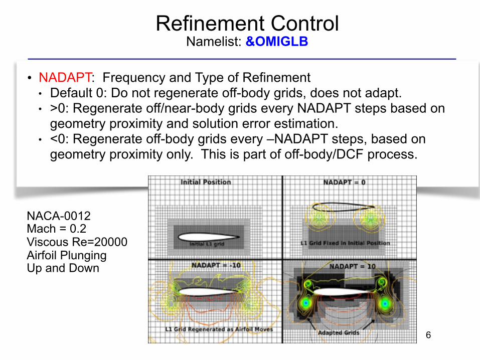
Refinement Control Namelist: &OMIGLB
• NADAPT: Frequency and Type of Refinement ● Default 0: Do not regenerate off-body grids, does not adapt. ● >0: Regenerate off/near-body grids every NADAPT steps based on
geometry proximity and solution error estimation. ● <0: Regenerate off-body grids every –NADAPT steps, based on
geometry proximity only. This is part of off-body/DCF process.
NACA-0012 Mach = 0.2 Viscous Re=20000 Airfoil Plunging Up and Down
6
7
Sensor Functions and Grid Marking Namelist: &OMIGLB
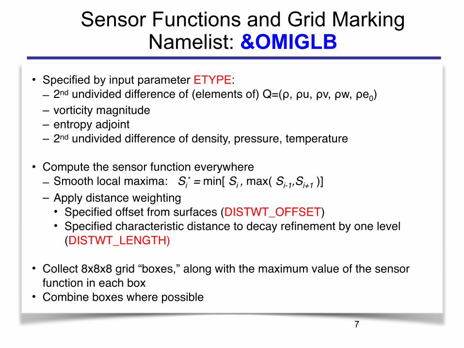
• Specified by input parameter ETYPE: – 2nd undivided difference of (elements of) Q=(ρ, ρu, ρv, ρw, ρe0)– vorticity magnitude– entropy adjoint– 2nd undivided difference of density, pressure, temperature
• Compute the sensor function everywhere– Smooth local maxima: Si
* = min[ Si , max( Si-1,Si+1 )]– Apply distance weighting
• Specified offset from surfaces (DISTWT_OFFSET)• Specified characteristic distance to decay refinement by one level
(DISTWT_LENGTH)
• Collect 8x8x8 grid “boxes,” along with the maximum value of the sensor function in each box
• Combine boxes where possible
8
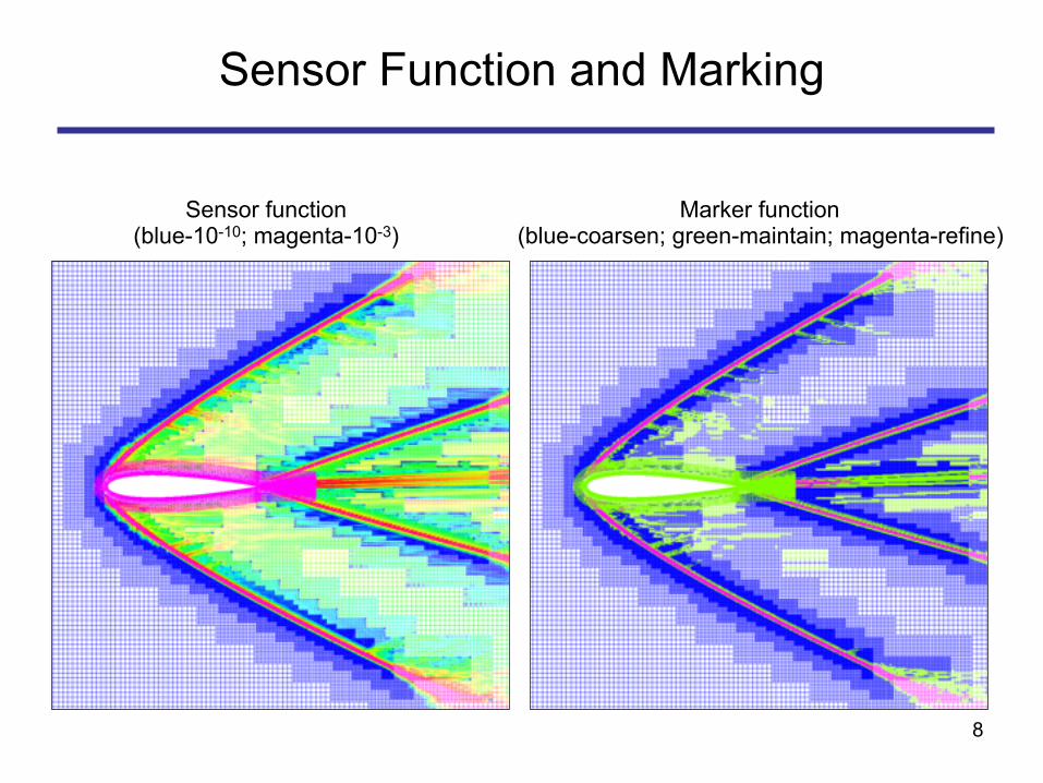
Sensor Function and Marking
Sensor function (blue-10-10; magenta-10-3)
Marker function (blue-coarsen; green-maintain; magenta-refine)

9
Grid Connectivity
• Hole cutting – All refinement grids get cut by geometry
(just like Level 1) • Blanking for refinement
– Next-finer grid level explicitly blanks out regions in current level
• Connectivity – Refinement grids can have
• Hole boundary points from geometry cuts • Hole boundary points from finer
refinement grids • Outer boundary points
Sample Level -1 grid blanking and interpolation stencils
10
Solution Interpolation onto Adapted Grids
Goals: • Process must be MPI-parallel, and include (re)load-balancing • Near-body and off-body grids are re-split and redistributed • Interpolation is performed in memory Process: • Create new near-body and off-body grid system • If needed, adjust grid adaption thresholds until grid resource limit is
satisfied • Create new splitting and distribution of near-body and off-body grids • MPI groups
• exchange/create new grids • exchange/interpolate solutions onto new grids

Plunging Airfoil
NACA-0012 Mach = 0.2 Viscous Re=20000 Airfoil Plunging Up and Down
11
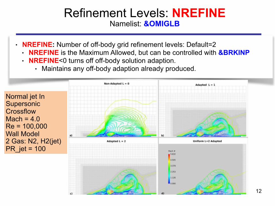
● NREFINE: Number of off-body grid refinement levels: Default=2 ● NREFINE is the Maximum Allowed, but can be controlled with &BRKINP ● NREFINE<0 turns off off-body solution adaption.
● Maintains any off-body adaption already produced.
Refinement Levels: NREFINE Namelist: &OMIGLB
Normal jet In Supersonic Crossflow Mach = 4.0 Re = 100,000 Wall Model 2 Gas: N2, H2(jet) PR_jet = 100
12

Normal Jet In Crossflow
Normal jet In Supersonic Crossflow Mach = 4.0 Re = 100,000 Wall Model 2 Gas: N2, H2(jet) PR_jet = 100
13

Refinement Levels: NBREFINE Namelist: &OMIGLB
● NBREFINE: Number of near-body grid refinement levels: Default=NREFINE ● NBREFINE is the Maximum Allowed, but can be controlled with &NBINP ● NBREFINE≤0 turns off near-body adaption.
● Maintains any near-body adaption already produced.
● Note: Near-Body refinement needs to maintain as much as possible of the original geometry of the surfaces. ● Compute parametric derivatives at cell corners using central differencing or one-
sided differencing, based on blending functions: ● Using cosine of grid turning angle ● Using grid stretching ratio
● All refinement levels are based on parametric cubic interpolation of original grid
Original grid Linear interpolation Parametric cubic interpolation
Parametric cubic interpolation with
blended differences 14

15
Controlling Grid Size and Growth Rate Namelist: &OMIGLB
● Desired coarsen/refine thresholds specified by ● SIGERR: lower [(1/8)SIGERR+2] and upper [(1/8)SIGERR] ● ECOARSEN/EREFINE: Solution error estimate level below/above which the
grid will be refined. (Defaults: [(1/8)SIGERR+2]/[(1/8)SIGERR]) ● Could be defined in term of function values, e.g. Vorticity
• Control grid size by specifying a maximum growth rate and/or a maximum overall grid size (parameters MAX_SIZE, MAX_GROWTH)
• Use specified coarsen and refine threshold values to compute size of adapted grid system – If max sensor value in box > refine threshold, mark box for refinement – If max sensor value in box < coarsen threshold, mark box for coarsening – Otherwise leave it alone
• If the maximum grid size is exceeded – Shift the coarsen and refine thresholds and recalculate – Use a binary search process to get within 3% of target MAX_SIZE

16
Controlling Off-Body Grids: BRICKS Namelist: &BRKINP
● User can create NBRICK, number of user-specified proximity regions ● Uses DS (L1 spacing parameter, see &GRDBRK) for uniform spacing for all
specified bricks. ● If NBRICK<0, user must specify ALL proximity regions (i.e., geometry will not
be used).
● The bounding box for each brick region (i=1,NBRICK) is specified by ● XBRKMIN(i),XBRKMAX(i),YBRKMIN(i),YBRKMAX(i),ZBRKMIN(i),ZBRKMAX(i)
● The brick can be uniformly refined to BRKLVL(i) ● Grid level for proximity region, in the range [1,-NREFINE].
● Proximity regions IBDYTAG(i) ● 0—Proximity region will have no body transformations. ● >0—Proximity region will be linked to this body ID for dynamic motion. ● DELTAS(i): Distance to expand proximity region (in all directions).

17
Controlling Off-Body Grids: Adaption Namelist: &BRKINP
● User can specify regions to restrict adaption to any level <= NREFINE
● For each region (i): bounding box for restriction defined by ● XREFMIN(i), XREFMAX(i), YREFMIN(i), YREFMAX(i), ZREFMIN(i), ZREFMAX(i) ● Where the level restriction is defined by
● REFLVL(i) Minimum grid level for limit region, in the range [2,-NREFINE] ● 0: Special value to freeze grid refinement in the limit region.
● For dynamic motion: IBDYREF(i) ● 0: Limit region will have no body transformations. ● >0: Limit region will be linked to this body ID for dynamic motion.
● Each region restriction can be controlled as inside or outside the bounding box ● REFINOUT(i): ● “INSIDE”: Grid level will be limited inside this region. ● “OUTSIDE”: Grid level will be limited outside this region.
● Note: The order of the regions sets the precedence ● If you restrict region=1 and contradict the restriction with region=2
● region=2 overrides the intersection with region=1
18
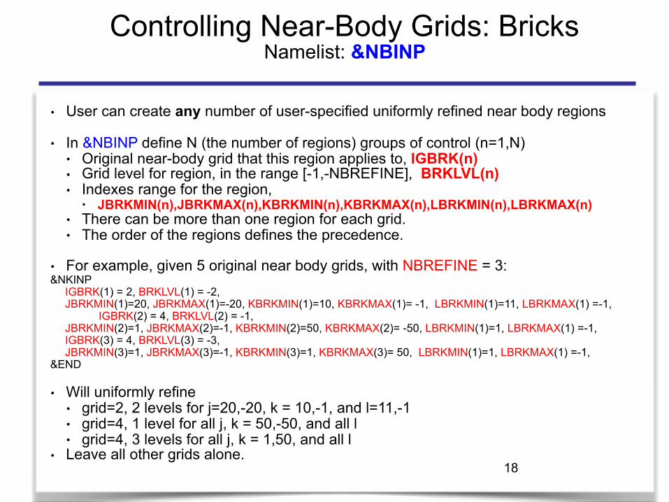
Controlling Near-Body Grids: Bricks Namelist: &NBINP
● User can create any number of user-specified uniformly refined near body regions
● In &NBINP define N (the number of regions) groups of control (n=1,N) ● Original near-body grid that this region applies to, IGBRK(n) ● Grid level for region, in the range [-1,-NBREFINE], BRKLVL(n) ● Indexes range for the region,
● JBRKMIN(n),JBRKMAX(n),KBRKMIN(n),KBRKMAX(n),LBRKMIN(n),LBRKMAX(n) ● There can be more than one region for each grid. ● The order of the regions defines the precedence.
● For example, given 5 original near body grids, with NBREFINE = 3: &NKINP IGBRK(1) = 2, BRKLVL(1) = -2, JBRKMIN(1)=20, JBRKMAX(1)=-20, KBRKMIN(1)=10, KBRKMAX(1)= -1, LBRKMIN(1)=11, LBRKMAX(1) =-1,
IGBRK(2) = 4, BRKLVL(2) = -1, JBRKMIN(2)=1, JBRKMAX(2)=-1, KBRKMIN(2)=50, KBRKMAX(2)= -50, LBRKMIN(1)=1, LBRKMAX(1) =-1, IGBRK(3) = 4, BRKLVL(3) = -3, JBRKMIN(3)=1, JBRKMAX(3)=-1, KBRKMIN(3)=1, KBRKMAX(3)= 50, LBRKMIN(1)=1, LBRKMAX(1) =-1, &END
● Will uniformly refine ● grid=2, 2 levels for j=20,-20, k = 10,-1, and l=11,-1 ● grid=4, 1 level for all j, k = 50,-50, and all l ● grid=4, 3 levels for all j, k = 1,50, and all l
● Leave all other grids alone.
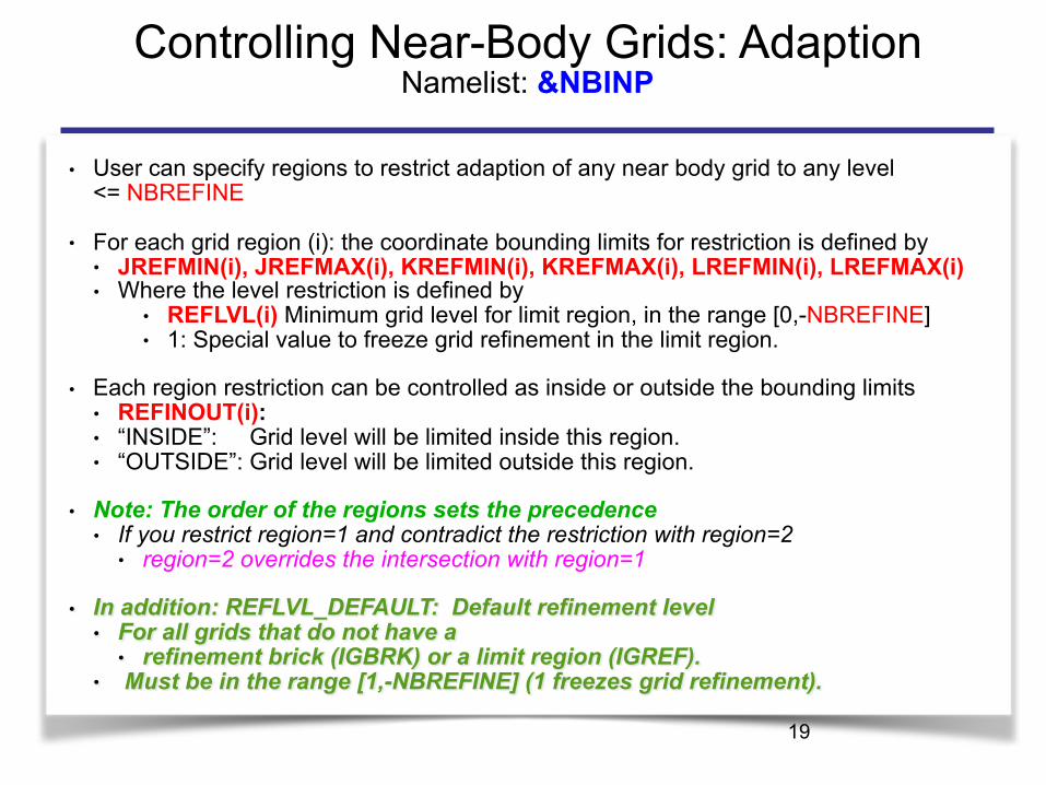
Controlling Near-Body Grids: Adaption Namelist: &NBINP
● User can specify regions to restrict adaption of any near body grid to any level <= NBREFINE
● For each grid region (i): the coordinate bounding limits for restriction is defined by ● JREFMIN(i), JREFMAX(i), KREFMIN(i), KREFMAX(i), LREFMIN(i), LREFMAX(i) ● Where the level restriction is defined by
● REFLVL(i) Minimum grid level for limit region, in the range [0,-NBREFINE] ● 1: Special value to freeze grid refinement in the limit region.
● Each region restriction can be controlled as inside or outside the bounding limits ● REFINOUT(i): ● “INSIDE”: Grid level will be limited inside this region. ● “OUTSIDE”: Grid level will be limited outside this region.
● Note: The order of the regions sets the precedence ● If you restrict region=1 and contradict the restriction with region=2
● region=2 overrides the intersection with region=1
● In addition: REFLVL_DEFAULT: Default refinement level ● For all grids that do not have a
● refinement brick (IGBRK) or a limit region (IGREF). ● Must be in the range [1,-NBREFINE] (1 freezes grid refinement).
19
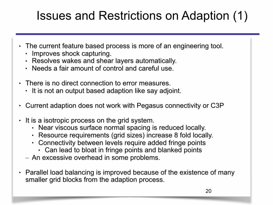
● The current feature based process is more of an engineering tool. ● Improves shock capturing. ● Resolves wakes and shear layers automatically. ● Needs a fair amount of control and careful use.
● There is no direct connection to error measures. ● It is not an output based adaption like say adjoint.
● Current adaption does not work with Pegasus connectivity or C3P
● It is a isotropic process on the grid system. ● Near viscous surface normal spacing is reduced locally. ● Resource requirements (grid sizes) increase 8 fold locally. ● Connectivity between levels require added fringe points
● Can lead to bloat in fringe points and blanked points – An excessive overhead in some problems.
● Parallel load balancing is improved because of the existence of many smaller grid blocks from the adaption process.
20
Issues and Restrictions on Adaption (1)

21
Issues and Restrictions on Adaption (2)
● Off-Body Adaption ● Requires a DCF (the Domain Connectivity Function) setup.
● e.g xrays are required. ● Works well with moving geometries. ● Can be applied to problems with
● Thin Near Body grids ● Conventional Near Body Grids.
Adapted grid system after one revolution Two levels of refinement Adaption performed every 10 steps (2.5 deg rotation) Much better resolution of tip vortices Grid size increases from 5M points to 67M points
Rotorcraft Example: UH-60 4-Bladed Rotor
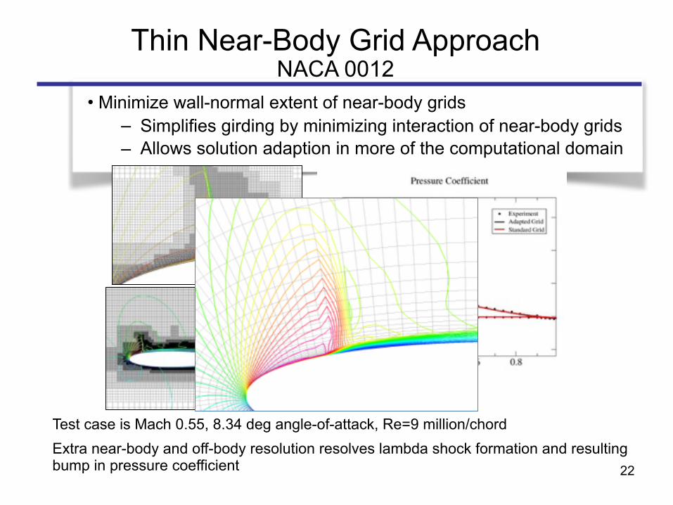
• Minimize wall-normal extent of near-body grids – Simplifies girding by minimizing interaction of near-body grids – Allows solution adaption in more of the computational domain
Test case is Mach 0.55, 8.34 deg angle-of-attack, Re=9 million/chord Extra near-body and off-body resolution resolves lambda shock formation and resulting bump in pressure coefficient
Thin Near-Body Grid ApproachNACA 0012
22
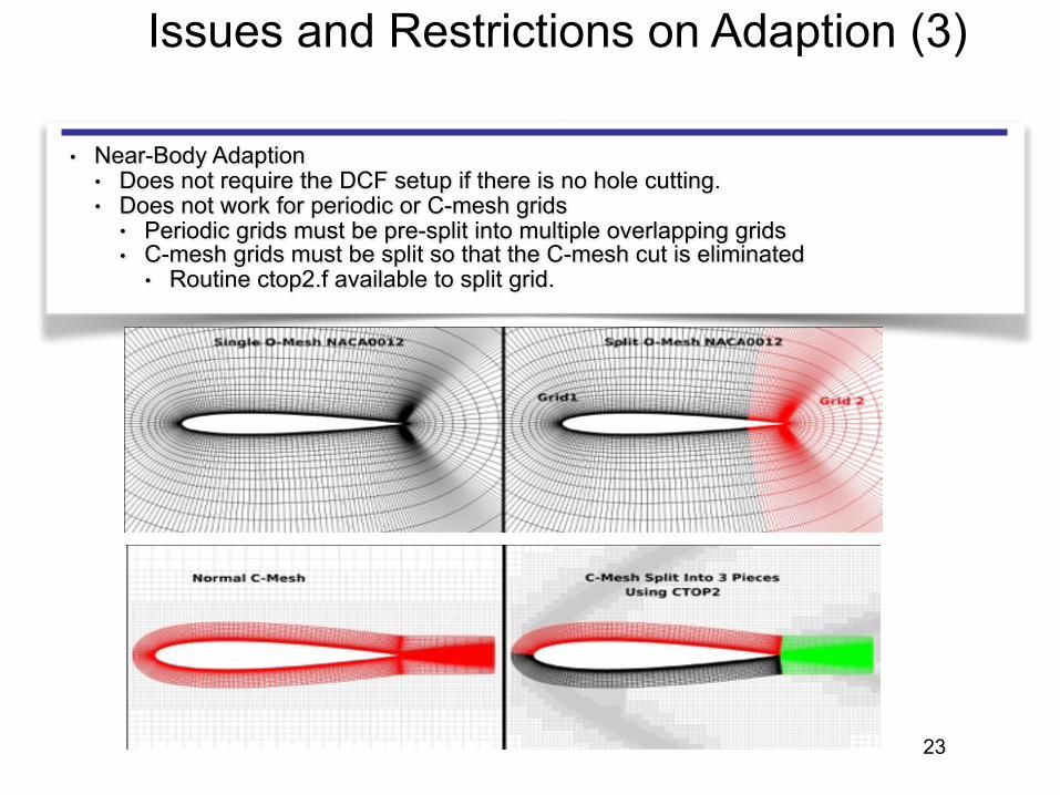
Issues and Restrictions on Adaption (3)
● Near-Body Adaption ● Does not require the DCF setup if there is no hole cutting. ● Does not work for periodic or C-mesh grids
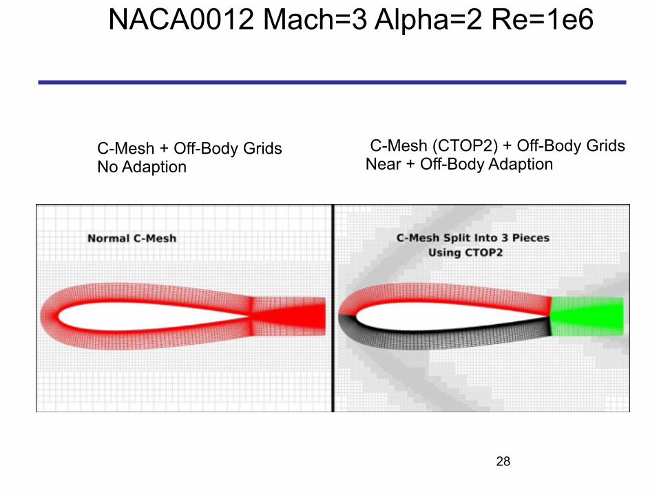
● Periodic grids must be pre-split into multiple overlapping grids ● C-mesh grids must be split so that the C-mesh cut is eliminated
● Routine ctop2.f available to split grid.
23

24
Examples
25
NACA0012 Mach=3 Alpha=2 Re=1e6
Single O-Mesh No Adaption
Split O-Mesh With Adaption
26
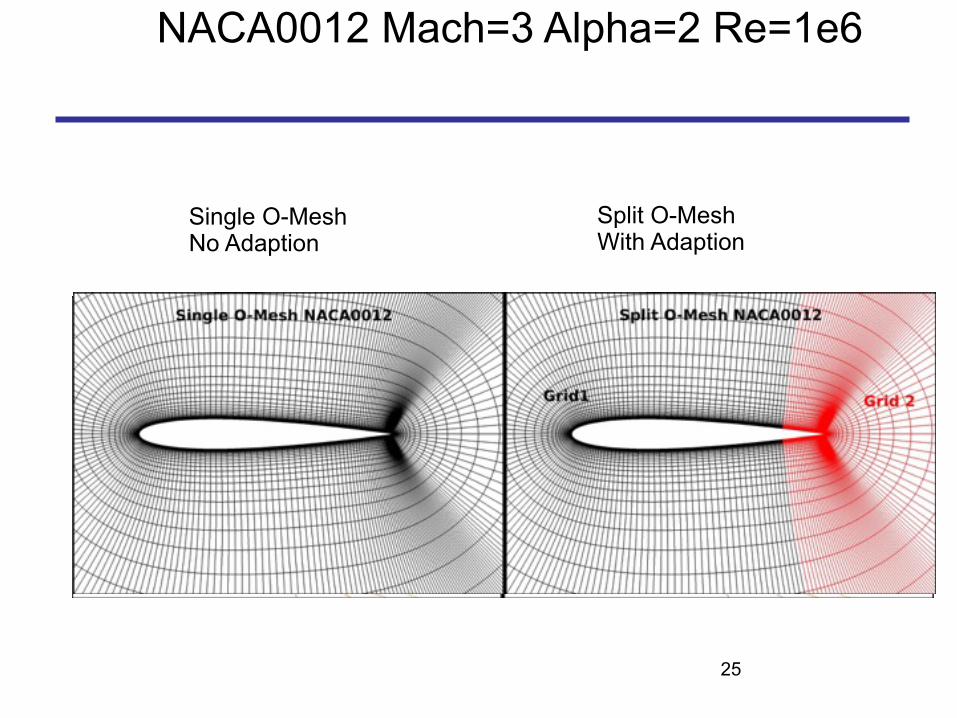
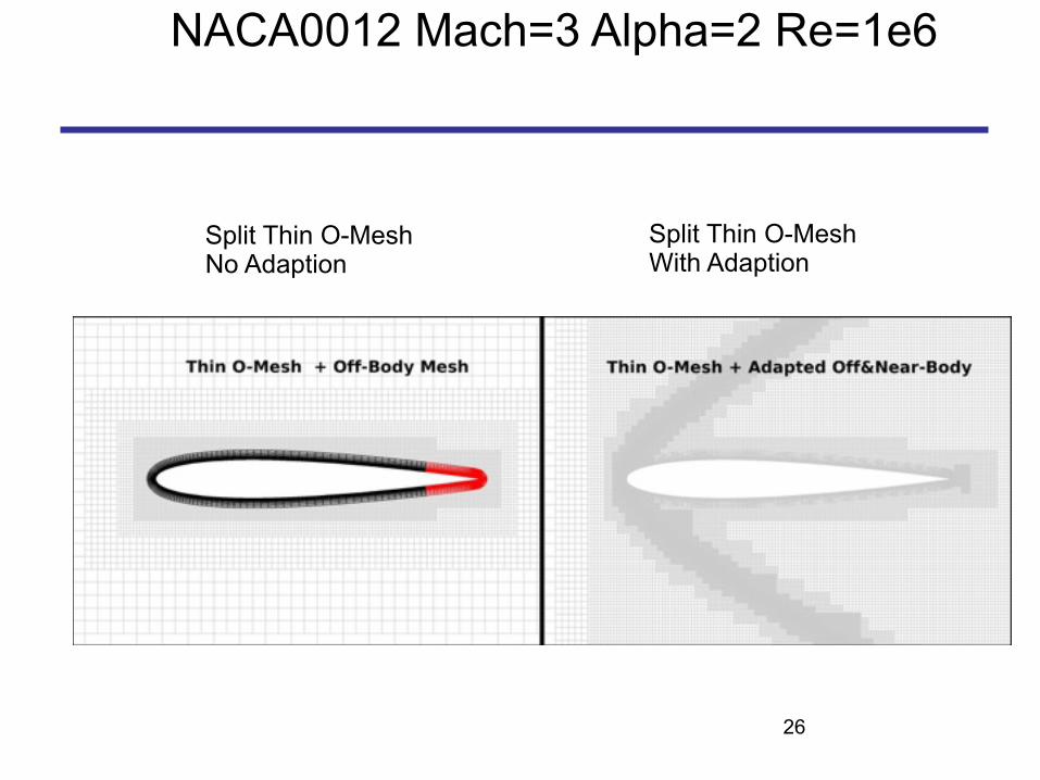
NACA0012 Mach=3 Alpha=2 Re=1e6
Split Thin O-Mesh No Adaption
Split Thin O-Mesh With Adaption
27
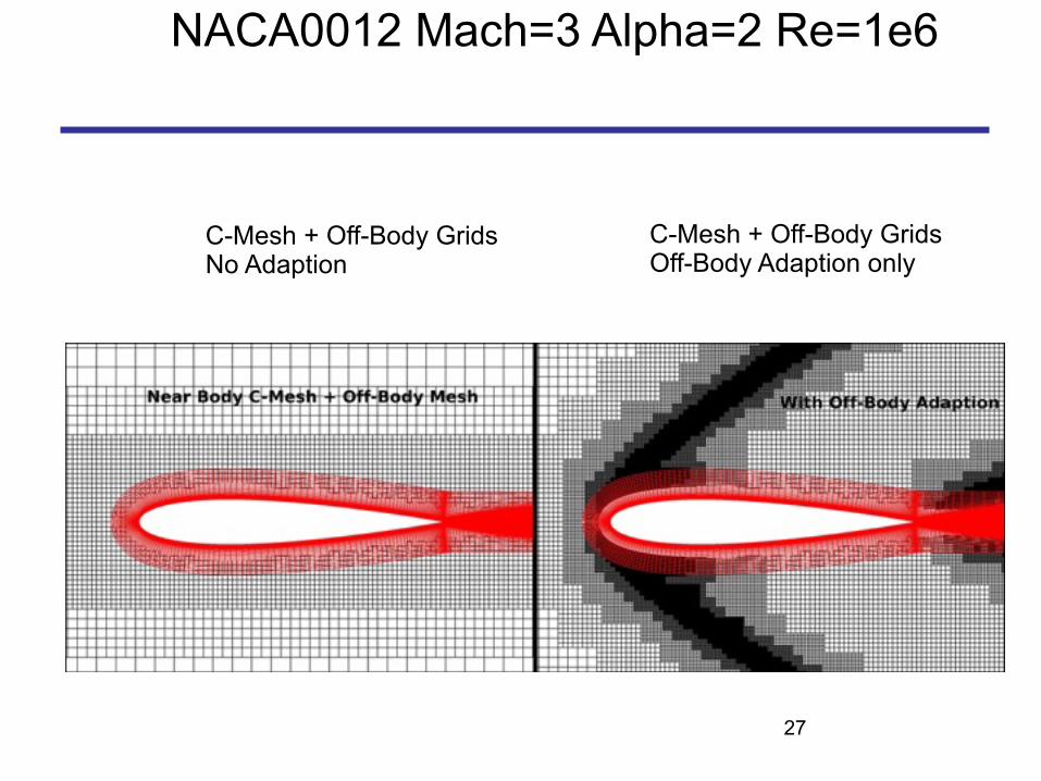
NACA0012 Mach=3 Alpha=2 Re=1e6
C-Mesh + Off-Body Grids No Adaption
C-Mesh + Off-Body Grids Off-Body Adaption only
28
NACA0012 Mach=3 Alpha=2 Re=1e6
C-Mesh + Off-Body Grids No Adaption
C-Mesh (CTOP2) + Off-Body Grids Near + Off-Body Adaption
29
2D Pitching Airfoil
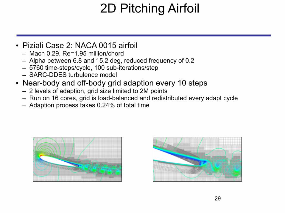
• Piziali Case 2: NACA 0015 airfoil – Mach 0.29, Re=1.95 million/chord – Alpha between 6.8 and 15.2 deg, reduced frequency of 0.2 – 5760 time-steps/cycle, 100 sub-iterations/step – SARC-DDES turbulence model
• Near-body and off-body grid adaption every 10 steps – 2 levels of adaption, grid size limited to 2M points – Run on 16 cores, grid is load-balanced and redistributed every adapt cycle – Adaption process takes 0.24% of total time

2D Pitching Airfoil
30
Rotorcraft ExamplesTRAM Tiltrotor in Hover
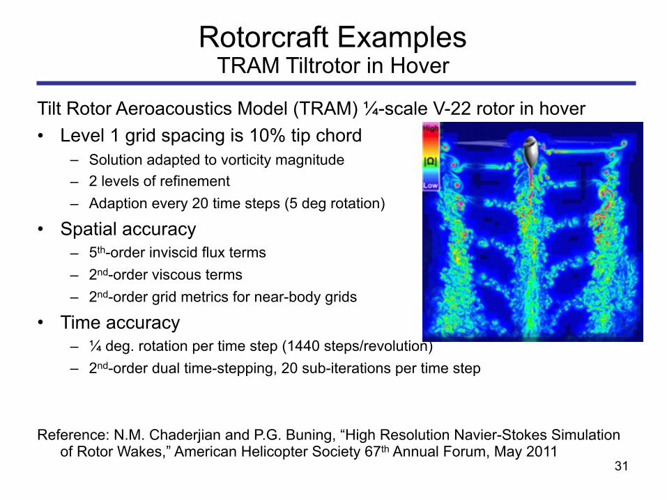
Tilt Rotor Aeroacoustics Model (TRAM) ¼-scale V-22 rotor in hover • Level 1 grid spacing is 10% tip chord
– Solution adapted to vorticity magnitude – 2 levels of refinement – Adaption every 20 time steps (5 deg rotation)
• Spatial accuracy – 5th-order inviscid flux terms – 2nd-order viscous terms – 2nd-order grid metrics for near-body grids
• Time accuracy – ¼ deg. rotation per time step (1440 steps/revolution) – 2nd-order dual time-stepping, 20 sub-iterations per time step
Reference: N.M. Chaderjian and P.G. Buning, “High Resolution Navier-Stokes Simulation of Rotor Wakes,” American Helicopter Society 67th Annual Forum, May 2011
31
Nozzle Example
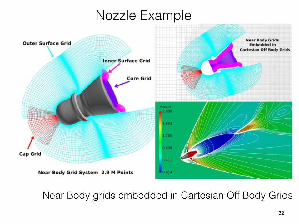
Near Body grids embedded in Cartesian Off Body Grids32
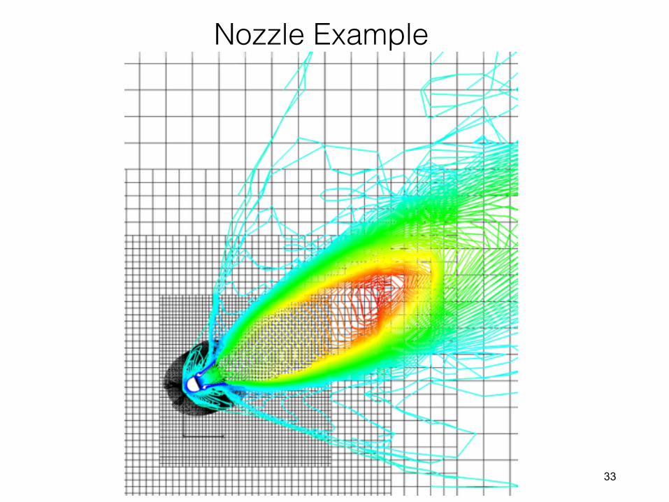
Nozzle Example
33

• a) Original grid solution • Note the poor looking contours are a result of the cutting plane across the general grids.
• b) Fixed the max_size (max total # of pts) = 50 Million • NB Level =2, OB Level = 3 does a reasonable job with shocks and shear layers. • NB adaption may be overkill
• c) max_size = 50M, OB Level =3 only adaption • d) max_size = 200M NB Level = 2, OB Level =4 : sharper features.
34
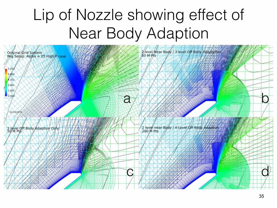
Lip of Nozzle showing effect of Near Body Adaption
a b
c d35
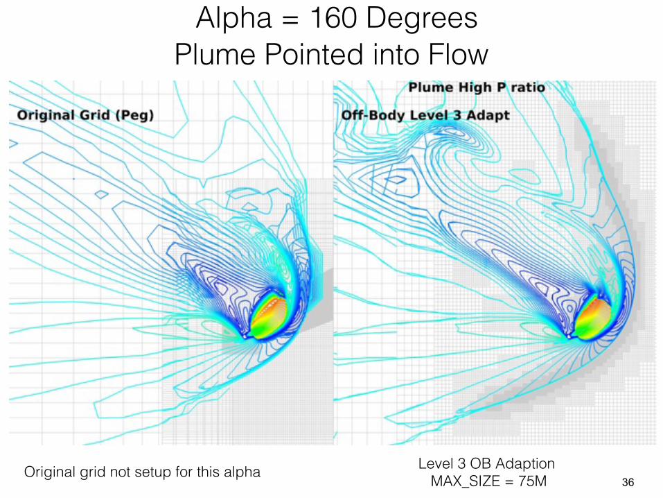
Original grid not setup for this alpha Level 3 OB Adaption MAX_SIZE = 75M
Alpha = 160 Degrees Plume Pointed into Flow
36

Alpha = 160 Degrees Plume Pointed into Flow
37
38
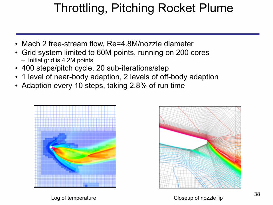
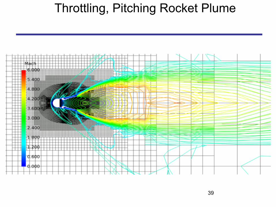
Throttling, Pitching Rocket Plume
• Mach 2 free-stream flow, Re=4.8M/nozzle diameter • Grid system limited to 60M points, running on 200 cores
– Initial grid is 4.2M points • 400 steps/pitch cycle, 20 sub-iterations/step • 1 level of near-body adaption, 2 levels of off-body adaption • Adaption every 10 steps, taking 2.8% of run time
Log of temperature Closeup of nozzle lip
39
Throttling, Pitching Rocket Plume
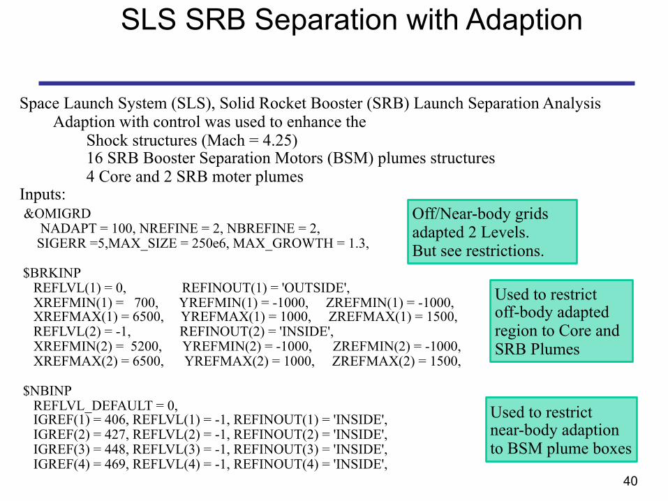
SLS SRB Separation with Adaption
Space Launch System (SLS), Solid Rocket Booster (SRB) Launch Separation Analysis Adaption with control was used to enhance the
Shock structures (Mach = 4.25) 16 SRB Booster Separation Motors (BSM) plumes structures 4 Core and 2 SRB moter plumes
Inputs: &OMIGRD NADAPT = 100, NREFINE = 2, NBREFINE = 2, SIGERR =5,MAX_SIZE = 250e6, MAX_GROWTH = 1.3,
$BRKINP REFLVL(1) = 0, REFINOUT(1) = 'OUTSIDE', XREFMIN(1) = 700, YREFMIN(1) = -1000, ZREFMIN(1) = -1000, XREFMAX(1) = 6500, YREFMAX(1) = 1000, ZREFMAX(1) = 1500, REFLVL(2) = -1, REFINOUT(2) = 'INSIDE', XREFMIN(2) = 5200, YREFMIN(2) = -1000, ZREFMIN(2) = -1000, XREFMAX(2) = 6500, YREFMAX(2) = 1000, ZREFMAX(2) = 1500,
$NBINP REFLVL_DEFAULT = 0, IGREF(1) = 406, REFLVL(1) = -1, REFINOUT(1) = 'INSIDE', IGREF(2) = 427, REFLVL(2) = -1, REFINOUT(2) = 'INSIDE', IGREF(3) = 448, REFLVL(3) = -1, REFINOUT(3) = 'INSIDE', IGREF(4) = 469, REFLVL(4) = -1, REFINOUT(4) = 'INSIDE',
Used to restrict off-body adapted region to Core and SRB Plumes
Used to restrict near-body adaption to BSM plume boxes
Off/Near-body grids adapted 2 Levels. But see restrictions.
40

Grids Systems
Typical Result from Original Grid System41

Grids Systems
Typical Result from Adapted Grid System42

Original grid solution
Total grid size = 350E6 NB Grids ~ 250E6 Boxes/OB Grids ~ 100E6
Adapted grid solution
Total grid size = 350E6 NB Grids ~ 250E6 Adapted/OB Grids ~ 100E6
43
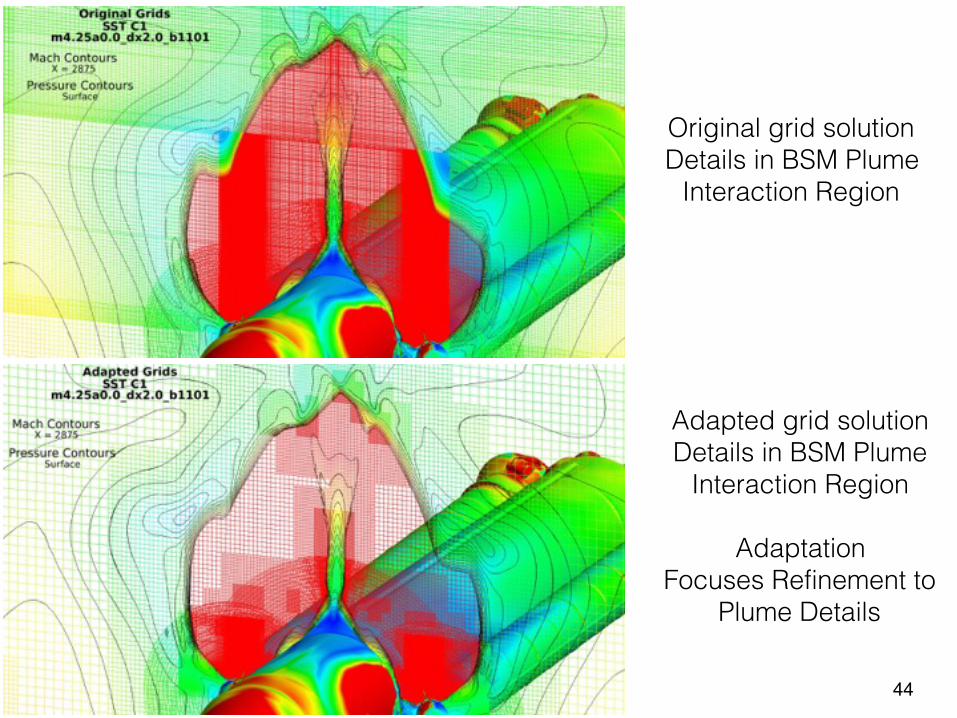
Original grid solution Details in BSM Plume
Interaction Region
Adapted grid solution Details in BSM Plume
Interaction Region
Adaptation Focuses Refinement to
Plume Details
44
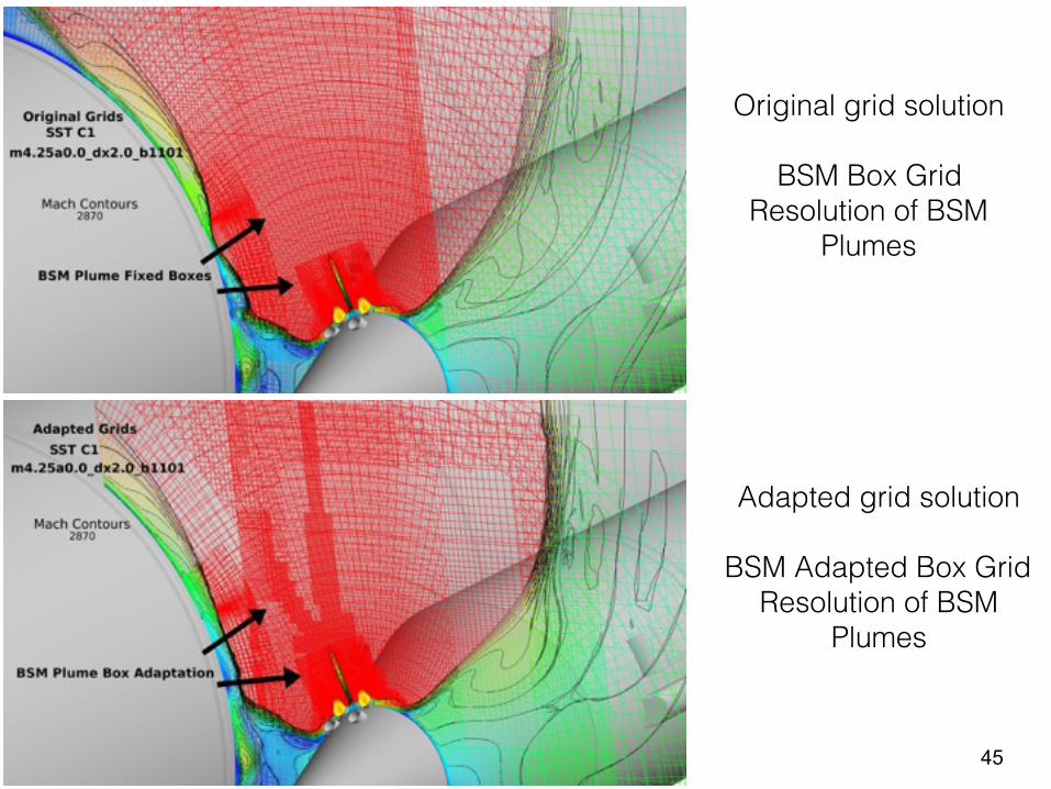
Original grid solution
BSM Box Grid Resolution of BSM
Plumes
Adapted grid solution
BSM Adapted Box Grid Resolution of BSM
Plumes
45
46
Problems and Future Work
• Parametric cubic interpolation for near-body grid adaption – Sometimes generates negative volumes
• usually related to highly-skewed original grids – Some rounding of corners < 45 deg – Coarse original grids can produce refined grids that are not as smooth as
desired
• Flow solver convergence degrades with more levels of refinement
• Consider other truncation error estimate or output-based error estimate – Truncation error estimators – Error redistribution – Adjoint
• Simplification and More automated control
47
Summary
• Solution adaption process has been developed in OVERFLOW for – Near-body grids (curvilinear) – Off-body grids (cartesian) – Adds to existing off-body adaption
• Parametric cubic interpolation used to generate refined grids – Blended central and one-sided differencing used to maintain sharp corners
• Implemented controls on – Grid size and growth rate – Regions of adaption
• Adaption is efficient enough for time-accurate, moving body simulations – Process is both MPI- and OpenMP-parallel
• Ready for Prime Time
48
References
• Buning, P., Pulliam, T., “Cartesian Off-Body Grid Adaption for Viscous Time-Accurate Flow Simulations”, AIAA 2011-3693, 20th AIAA Computational Fluid Dynamics Conference, June 27 - 30, 2011, Honolulu, Hawaii
• Buning,P., Pulliam T., “Near-Body Grid Adaption for Overset Grids”, AIAA 2016-3326 Aviation 2016, Washington , D.C. June 13-17, 2016
• Lee, H., Pulliam ,T., “Studying the Effects of Grid Generation Strategies and Grid Adaption on Airplane Geometries using OVERFLOW”, AIAA 2011-3985, 20th AIAA Computational Fluid Dynamics Conference, June 27 - 30, 2011, Honolulu, Hawaii
• N.M. Chaderjian and P.G. Buning, “High Resolution Navier-Stokes Simulation of Rotor Wakes,” American Helicopter Society 67th Annual Forum, May 2011
49
NAMELIST: &OMIGLB
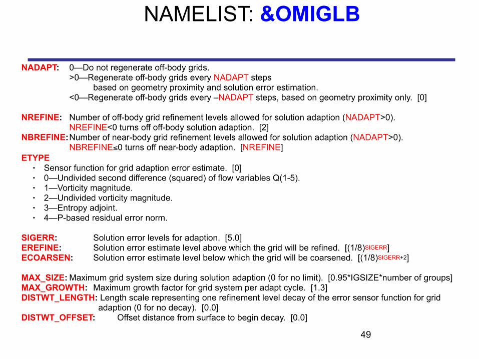
NADAPT: 0—Do not regenerate off-body grids. >0—Regenerate off-body grids every NADAPT steps based on geometry proximity and solution error estimation. <0—Regenerate off-body grids every –NADAPT steps, based on geometry proximity only. [0]
NREFINE: Number of off-body grid refinement levels allowed for solution adaption (NADAPT>0). NREFINE<0 turns off off-body solution adaption. [2] NBREFINE: Number of near-body grid refinement levels allowed for solution adaption (NADAPT>0). NBREFINE≤0 turns off near-body adaption. [NREFINE] ETYPE
● Sensor function for grid adaption error estimate. [0] ● 0—Undivided second difference (squared) of flow variables Q(1-5). ● 1—Vorticity magnitude. ● 2—Undivided vorticity magnitude. ● 3—Entropy adjoint. ● 4—P-based residual error norm.
SIGERR: Solution error levels for adaption. [5.0] EREFINE: Solution error estimate level above which the grid will be refined. [(1/8)SIGERR] ECOARSEN: Solution error estimate level below which the grid will be coarsened. [(1/8)SIGERR+2]
MAX_SIZE: Maximum grid system size during solution adaption (0 for no limit). [0.95*IGSIZE*number of groups] MAX_GROWTH: Maximum growth factor for grid system per adapt cycle. [1.3] DISTWT_LENGTH: Length scale representing one refinement level decay of the error sensor function for grid adaption (0 for no decay). [0.0] DISTWT_OFFSET: Offset distance from surface to begin decay. [0.0]

50
NAMELIST: &BRKINP
NBRICK: Number of user-specified proximity regions. If NBRICK<0, user must specify ALL proximity regions (i.e., geometry will not be used). [0]
XBRKMIN(brick#),XBRKMAX(brick#): X-range of user-specified proximity region. YBRKMIN(brick#),YBRKMAX(brick#): Y-range of user-specified proximity region. ZBRKMIN(brick#),ZBRKMAX(brick#): Z-range of user-specified proximity region.
BRKLVL(brick#): Grid level for proximity region, in the range [1,-NREFINE]. [1] IBDYTAG(brick#): 0—Proximity region will have no body transformations. >0—Proximity region will be linked to this body ID for dynamic motion. [1]
DELTAS(brick#): Distance to expand proximity region (in all directions). [0.]
XREFMIN(region#), XREFMAX(region#): X-range of error adaption limit region. YREFMIN(region#), YREFMAX(region#): Y-range of error adaption limit region. ZREFMIN(region#), ZREFMAX(region#): Z-range of error adaption limit region.
REFLVL(region#): Minimum grid level for limit region, in the range [2,-NREFINE]. 0—Special value to freeze grid refinement in the limit region. [2]
IBDYREF(region#): 0— Limit region will have no body transformations. >0—Limit region will be linked to this body ID for dynamic motion. [0]
REFINOUT(region#): “INSIDE”—Grid level will be limited inside this region. “OUTSIDE”—Grid level will be limited outside this region. [“OUTSIDE”]
51
NAMELIST: &NBINP
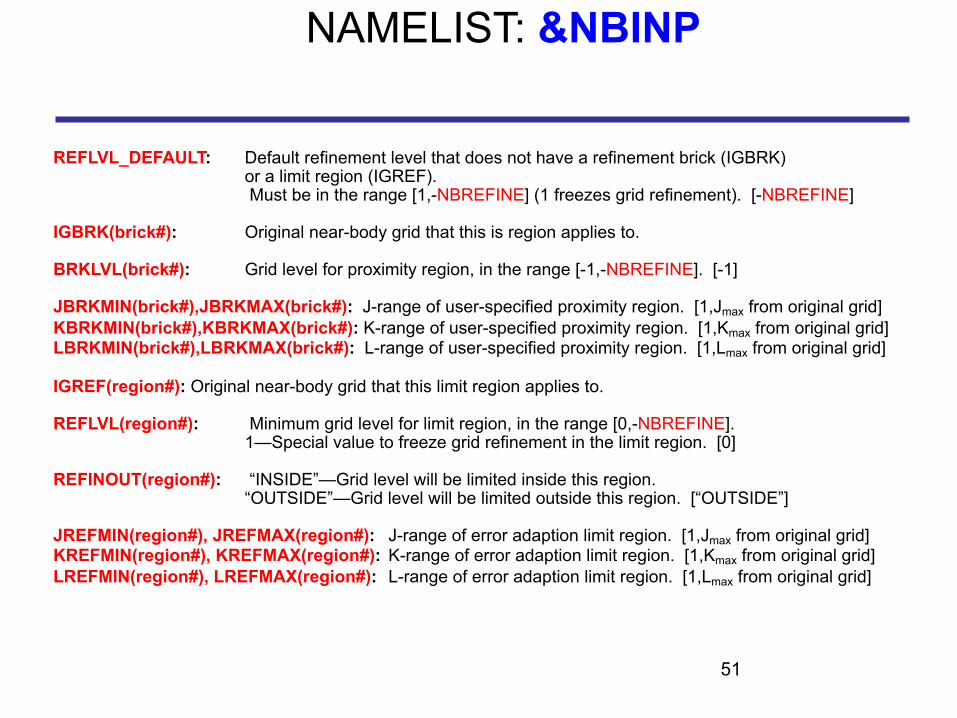
REFLVL_DEFAULT: Default refinement level that does not have a refinement brick (IGBRK) or a limit region (IGREF). Must be in the range [1,-NBREFINE] (1 freezes grid refinement). [-NBREFINE]
IGBRK(brick#): Original near-body grid that this is region applies to.
BRKLVL(brick#): Grid level for proximity region, in the range [-1,-NBREFINE]. [-1]
JBRKMIN(brick#),JBRKMAX(brick#): J-range of user-specified proximity region. [1,Jmax from original grid] KBRKMIN(brick#),KBRKMAX(brick#): K-range of user-specified proximity region. [1,Kmax from original grid] LBRKMIN(brick#),LBRKMAX(brick#): L-range of user-specified proximity region. [1,Lmax from original grid]
IGREF(region#): Original near-body grid that this limit region applies to.
REFLVL(region#): Minimum grid level for limit region, in the range [0,-NBREFINE]. 1—Special value to freeze grid refinement in the limit region. [0]
REFINOUT(region#): “INSIDE”—Grid level will be limited inside this region. “OUTSIDE”—Grid level will be limited outside this region. [“OUTSIDE”]
JREFMIN(region#), JREFMAX(region#): J-range of error adaption limit region. [1,Jmax from original grid] KREFMIN(region#), KREFMAX(region#): K-range of error adaption limit region. [1,Kmax from original grid] LREFMIN(region#), LREFMAX(region#): L-range of error adaption limit region. [1,Lmax from original grid]