Embed Size (px)
Citation preview

AD-A158 134
UNCLASSIFIED
EVALUATION OF GLASS FIBER REINFORCED CONCRETE PANELS FOR USE IN MILITARY. . (U) CONSTRUCTION ENGINEERING RESEARCH LAB (ARHV) CHAMPAIGN IL G R WILLIAMSON JUN 84 CERL-TR-N-85/15 F/G 13/3
1/1
i

ffiVur^:vX WV ^»•r;-r^^rg^,-:'--:' ^»Sun;*.^
5
|r. • 2 5
|» BS-IS
SKS Hi •!•
|»
1^
1-4 11
IIIIÜ
NATIONAL BUREAU OF STANOAROS wtHccrr RCMLUTKM mr CMMT
.»•'• • r* »• »^ »^ • • • •
* " « • • H . » fc • » k * • *
i :<••:>•
v>.v.v.v: •.%•
• iii'if fti
.'-•.V. ••> .v.v.v; .-.••
J> J- • - • - • » • _p » • • _^ _• fc» * • • i
•." *."•.•.'-.*• •«.«".•-«.'. , - . • . • « • . ' . « . • ^.- «J1 • « . *, • « - « • . • v* *." - " O «." - " Ox.* v* ^" •
> .V

I--3.-y^>ar-~--T^^.V.---.^'^^..nA-:/.--L^..%^^^^inirT^^-.-txv-jTrj%jJwjmji m !.§.!
US Army Corps of Engineers Construction Engineering Research Laboratory
i=h-C=iU.
TECHNICAL REPORT M-85/15 June 1985
AD-A158 134
0~-
8
Evaluation of Glass Fiber Reinforced Concrete Panels for Use in Military Construction
by Gilbert R. Williamson
Glass fiber reinforced concrete (GFRC) materials are investigated for potential use in military construc- tion, especially as exterior building panels. Because GFRC technology is relatively new, long-term dura- bility data are lacking. However, reliable aging tests have been designed that allow the material's per- formance to be predicted past the 50-year lifetime required for military construction.
Results indicate the GFRC panels are suitable for use in military construction. These materials may, in many cases, provide an economical alternative to conventional construction. The recommendation for their acceptance includes the stipulation that proven methods be used in the panels' design and applica- tion (e.g., steel stud frame backup and "L" anchors).
Approved for public release; distribution unlimited. \
85 8 19 068 A/»
%
.-
i
\
.-:-•:-.-•-.•:-.->• y yy -y-yw
&
."- *^vj

; v M^.-H-.TM»'Z^.J.?I.^S.JJ.^V^^"».•"....••'•••!.•:•-»:"•••• •:.-.^••:.'.'•.-TJ».;*:-. iL-.'.•*.-• «i- ^i^;^; TT.^CT
The contents or this report are not to be used for advertising, publication, or promotional purposes. Citation of trade names does not constitute an official indorsement or approval of the use of such commercial products. The findings of this report are not to be construed as an official Department of the Army position, unless so designated by other authorized documents.
DESTROY THIS REPORT WHEN IT IS NO LONGER NEEDED
DO NOT RETURN IT TO THE ORIGIN A TOR
•;
i
V.'
r-
i 8
-.1
K
v
a

"-»*_."" »XiTi.'S ;v^v^3 ••• I.» ».•-.» ._• -'' -.1.1". .". ." . >•'. •-• T. y."
UNr.l.ASSTFTF.I. SECURITY CLASSIFICATION OF THIS PACE (When riete entered)
REPORT DOCUMENTATION PAGE r REPORT NUMBER
CERL TR M-85/15
»AGE I READ INSTRUCTIONS BEFORE COMPLETING FORM
SSION^gq>/ WtOPlENT'S CATALOG NUMBER
4 TlT L F lend Subtitle)
EVALUATION OF GLASS FIBER REINFORCED CONCRETE PANELS FOR USE IN MILITARY CONSTRUCTION
7. AuTHOfif«)
Gilbert R. Williamson
9 PERFORMING ORGANIZATION NAME AND ADDRESS
U.S. Army Construction Engr. Research Laboratory P.O. Box 4005 Champaign, IL 61820
II. CONTROLLING OFFICE NAME AND ADDRESS
U MONITORING AGENCY NAME a AOORESSfff different from Controlling Office)
TYPE OF RETORT 4 PERlOO COVERED
Final
6 PERFORMING ORG. REPORT NCMBER
8. CONTRACT OR GRANT NUMBER/.)
10. PROGRAM ELEMENT. PROJECT. TASK AREA 4 WORK UNIT NUMBERS
FAD 2-001773, dated February 1984
12. REPORT DATE
June 1984 If. NUMBER OF PACES
25 'S SECURITY CLASS, (of thle report)
Unclassified IS« OECL ASSIFl CATION DOWNGRADING
SCHEDULE
16 DISTRIBUTION STATEMENT (ol 'htm Report)
Approved for public release; distribution unlimited.
17 DISTRIBUTION STATEMENT (ol the ebmtrect entered In Block 20, It different Irom Report)
It SUPPLEMENTARY NOTES
Copies are obtainable from the National Technical Information Service Springfield, VA 22161
1 KEY WOROS (Continue on rereree eld» II net: em eery end Identity by block number)
20 ABSTRACT rCanttaumJ en rereree eleem H rrexeeeery erntet Identity by blorl, number)
"'Glass übet reinforced concreit (GrRC) materials are investigated for potential use in military construction, especially as exterior building panels. Because GFRC technology is relatively new. long-term durability data arc lacking. However, reliable aging tests have been designed that allow the material's pertormunce to be predicted past the 50-ycar lifetime required lor military construction.
Results indicate the til-RC panels are suitable for use in military construction. These materials may, in many cases, provide an economical alternative to conventional con-
DO \jneT\3 1473 EDlTio» OF > MOV «S !•> OBSOIETI JJNCJAS£J£IEP
SECURITY CLASSIFICATION OF TM-S P» ,E 'When Pete fntrre-1)
tää^ A?

•rr •«.•>.•• v. .' v.\'; .1".'.n." .'- /-".•>"."• ".••• .*•".••"."• ,."! ^ '^- '• v« .\.T7*..iTr»j.,Ti->\* •* •> •> •-> WXW.W/.-.*.
UNCLASSIFIED
'^. »-. ^.TT.rr^<r.^-
HCUWITV CLAStlFICATIOM OF THIS P AGEfaTian D«(a gntara«
BLOCK 20 (Cont'd)
struct ion. The recommendation for their acceptance includes the stipulation that proven
methods 10 be used in the panels' design and application (e.g.. steel stud frame backup
and^L" anchors). I» \
irNCI-ASSIFTED
»tCuHiTv CL »»»I»IC»TIO*. or THIS PAGC'OTian Dai« Bnttrtd)
• •.-.•••.•.•.•••.• .^ . "j,«. •• «.% »•••-•>" »%>N • ".• .• " • • .«v -% «v JN -N ."•••- »> •••-.-.• .^ . > . • .V . • A . •«•*_*•" *.' ft." * • \." V' • • *.' ft*V* ft.* »* ».• ftj" •_* • *• • ft_ • " • * O . ' ft* ft." V** ft_* ***.* •.••." V" *.••»••_• ft -.*•*•*•' ft_ft «^* ft •. •
."--"• -~».-vgvL,v.'M.-i.i_,v.,». .^.'.T..%'.'.n:'.v.* ".v..», '"•.' .»."».• '•:••.,.'vs.1..'.;«.' '.;•:: <•.• <, r: c v v^~»—r-i
FOREWORD
This work was performed for the Directorate of Engineering and Construction, Office of the Chief of Engineers, under Funding Authorization Document 2-001773, dated February 1984. The technical monitor was Fred Anderson, DAEN-ECE-D.
The work was done by the U.S. Army Construction Engineering Research Laboratory (USA-CERL), Engineering and Materials Division (EM). Dr. Robert Quattrone is Chief, EM.
Appreciation is expressed to the following persons for supplying information used in this study. H. P. Ball. Jr., Ball Consulting, Ltd.; J. F.Covington.G.F.R.C. Systems, Inc.; W. S. Hutchins, Olympian Stone Co., Inc.; J. M. Magnuson, GFRC Texas, Inc.; H. J. Malloy, Henry J. Malloy and Associates; Wars Rcnemans, GFRC, Inc.; and J. W. Smith, I. J. Morrison, and J. Colvin, Pilkington Brothers, Ltd.
COL Paul J. Theuer is Commander and Director of USA-CERL, and Dr. L. R. Shaffer is Technical Director.
IS ÖRA41 ! DXIC TAB
• .- . euncid Justlfi«
i
<VA,V:V.V.V.V
'.'.'V.v v;
-*— +- *- '- ^*- • • • 1 .
::-.:i- '•. .
Aval] iMli
|A\ U E Dlst Special
• v •.• .^
i^w: :;>>>:; ^-^ • - J

!>*^ .V.* A .* .M'.V .V " •-'.'." _V_*?*? *."*.'l.'. '-• l." I'»1." l"" '•" -•-'•.••:'•.' <-.'»-.• .. '• ->-j«-;i-; :-.•-•; v..-. J-J r. :
. •r. •'. •'. •". "" •••-"-• "-
CONTENTS
Page
DD FORM 1473 1 FOREWORD 3 LIST OF TABLES AND FIGURES 5
1 INTRODUCTION 7 Background Objective Approach
2 GFRC MATERIALS MANUFACTURE AND PROPERTIES 8 Composition Aging
3 LONG-TERM EVALUATION OF GFRC INSTALLATIONS 16
4 PANEL PRODUCTION AND PRACTICE IN THE UNITED STATES 18
5 CONCLUSIONS AND RECOMMENDATIONS 19
REFERENCES 23
APPENDIX: Recommended Criteria for the Design, Manufacture, and 25 Erection of Glass Fiber Reinforced Concrete (GFRC) Panels
DISTRIBUTION
•>
-:-
53

• •-1TV..VIV.iJ* V* •.»'•.< ...» • •'- »'. »• * .i.y; *». »'. t-. L-;^. "*. -".'-'.' :•
TABLES
Number Page
1 GFRC Properties 8
2 PGFRC Properties 9
3 Measured Mean Strength of Sprayed-Dewatered OPC/GFRC at 11 Various Ages
FIGURES
1 Representative Stress-Strain Curves in Tension and Bending 10
9 Bending Strength Development Under Accelerated Aging at 50°C Under Water 16
!
•3
Strain-to-Failure in Tension for GFRC at Various Ages in Dry Air, Natural Weather, and Water Storage 12
H
3 Cem-FIL Fiber Strengths From SIC Tests Under Accelerated Aging Conditions 13
4 Flexural Strengths of GFRC Composite After Accelerated Aging and Weather Exposure 13
5 SIC Specimen Reaction Time to Reach a Given Strength 13
6 Cem-FIL GFRC Strength Retention in Natural Weather, United Kingdom, Compared With Predictions From Accelerated Aging Tests at 50°C, 60°C, r, and 80°C 14 >
f 7 Retention of Strain-to-Failure in Bending for Cem-FIL 1 and Cem-FIL 2 jjj
GFRC Composites 15 ^
8 Results of Accelerated Aging Bending Test on E-glass Mixes With and Without Polymer 15
10 Results of Curing Tests on AR-Glass Specimens-LOP Versus Age 17
11 Typical Steel Stud Framing Used in the United States 20 *.
12 "L"-Shaped Anchor Used to Secure Panels to the Steel Frame 20 $
13 Panels With Built-Up Ribs as Stiffeners 21
14 GFRC Use on a Bank Building in Dallas, TX 21
15 Hotel Facade in Seattle, WA 22
16 Office Building in Nashville, TN 22
tmmmmmmmmmmtmm-mmmmmxi

'•» ^»^.^•^•t7^T.v.\v/^^v.vv.J.,.",,.v,'.v.v.,.i7.«: • .• '••-«--•»T»
PREVIOUS PACE IS BLANK
EVALUATION OF GLASS FIBER REINFORCED CONCRETE PANELS FOR USE IN MILITARY CONSTRUCTION
INTRODUCTION
Background Glass fiber reinforced concrete (GFRC) panels have,
in the past 10 years, become widely used throughout the world. Several U.S. Army Corps of Engineers Districts and Divisions have received requests from the GFRC industry to consider bids that specify GFRC as an alternative exterior panel material for military construction projects. When the GFRC products have been compared with conventional panels, it has been found that considerable savings could be effected if the GFRC panels were used. However, before permit- ting general use of this material, the Directorate of Engineering and Construction, Office of the Chief of Engineers, commissioned a study to determine the material's suitability for military construction. Per- manent military construction normally is expected to have a 50-year life.
GFRC is a relatively new technology. Many previous attempts had been made to use glass bars as tensile reinforcement in ordinary Portland cement (OPC) concrete but none had been successful. Alkali in the cement causes rapid deterioration of conventional borosilica glass, commonly called "E-glass," rendering the bars ineffective after only a few years. Glass was, however, found to be very effective in reinforcing plastics, and a huge industry offering an enormous number of products resulted from this application. Glass fibers are the primary reinforcement used in these products. Success with this technology renewed the interest in using glass fibers as reinforcement for concrete products, but the prior experience with glass reinforcing bars made it apparent that a way to protect the glass from alkali was necessary.
product marketed under the name "AR" glass and produced by Cem-FIL Corporation and Nippon Electric Company.' This is a high-zirconia (minimum 19 percent), alkali-resistant glass that, after some slow deterioration due to the alkali, reaches a point at which no further deterioration takes place. The second approach, developed by Dr. J. Bijen, was to incorpor- ate approximately 15 percent by weight of a polymer marketed under the trade name "FORTON" as the E-glass protective agent.2
Based on these developments, a large GFRC indus- try developed worldwide. The term "GFRC" applies to products manufactured using a cement/aggregate slurry reinforced throughout with glass fibers. Products include formwork, nonpressure pipe, corrugated and plain sheets, asbestos replacement products, and archi- tectural and industrial panels (cladding) and surface bonding. Paneling is by far the most widely produced of all the products, with surface bonding comprising the second largest market. Because of its versatility and low cost, architects are specifying GFRC paneling at an ever increasing rate. Use of GFRC panels is common in Europe, Japan, the United Kingdom, the United States, and South Africa, as well as in the Middle East, where over 123 projects using GFRC materials have been completed since 1977.
Objective The objective of this study was to investigate
GFRC materials to determine their suitability, from a durability standpoint, for military construction, par- ticularly as paneling for building exteriors.
Approach The study was conducted by: reviewing the litera-
ture; visiting the British Research Establishment and Pilkington Brothers Ltd., the company developing AR-glass and thus founding the GFRC industry; visiting five different GFRC producers in the United States; and consulting with other experts in this field.
a
*.
i
.-
Three approaches to this problem were to: (1) develop an alkali-resistant glass; (2) use conventional (-glass, but incorporate an additive to protect it; (3) use E-glass with special cements such as alumina cement and gypsum slag. All three approaches pro- duced some degree of success. Work by Dr. A. J. Majumdar and others at the Building Research Estab- lishment (BRE) Watford, England, resulted in a
'A. J. Majumdjr and i. I . Ryder, "Glass-Fibre Reinforce- ment of Cement Products," Class Technology. Vol 9, No. 3 (June 1968).
'J. Bijen, "I.-Glass Fibre Reinforced Polymer Modified Cement," Proceedings. International Congress on Glass Fibre Reinforced Cement. London, Ont., 1979 (Glass Fibre Re- inforced Cement Association, 1980).
| MtVM PREVIOUS PAGE < BLANK
v V-W. >v->l^ Ä-V^>V>>;

TT7-T-
GFRC MATERIALS MANUFACTURE AND PROPERTIES
The most widely used process for producing CiFRC panels is the direct spray or spray-up process, which can be done by hand or machine. The process uses a two-nozzle compressed-air-powered gun, with one no/zle fed a continuous strand of glass fibers which is chopped at the nozzle into predetermined lengths of between 25 and 40 mm or 37 and 50 mm. The chopped fibers arc randomly combined with a cement- sand slurry from the second nozzle outside the gun after each material has been sprayed (blown at lügh speed) through its respective nozzle. The material is laid down in thin sections and the required thickness is achieved by making multiple spray passes over this form. The sections are hand-rolled after each pass to consolidate the material and eliminate air potkets. This same procedure (without the rolling) is sometimes followed by a dewatering process that not only in- creases the material's strength, but also allows for im- mediate removal from the form and bending into various shapes if desired. Panels and other products
also can be produced by mixing and casting the material as with other precast concrete products. The material is cured in the same way as for other concrete products cither by moist curing, membrane curing, or incorporating polymers into the mix.
Composition GFRC is composed of 1 part cement, 0.2 to 1.0
part sand, and 4 to 6 percent glass fibers by weight, and a water/cemen; ratio of approximately 0.3. Poly- mer GFRC (PGFRC) usually is composed of 1 part cement, 0.2 to 1 0 part sand, 4 to 6 percent glass fibers by weight, 10 to 15 percent polymer by volume, and enough water to produce a sprayable slurry. Water- reducing and other admixtures are used as required in these mixes. The cement for both PGFRC and GFRC usually is OPC, type I, sometimes white; sand usually is fine silica or fine regular type, and the AR- glass fiber is supplied in a roving (made up of strands that contain 204 monofilaments) which is chopped into lengths of 25 to 50 mm during the spraying process. Tables 1 and 2 give typical 28-day physical properties for GFRC and PGFRC, respectively; recom- mended design properties also are given.
Tablet
GFRC Properties (Recorded at 28 Days)*
Hand-or Recommended Property Unit Machine-Spray Design Value
AR liber content %by wt 5 Density (normal) ton/m1 1.9-2.1
(oinprcssive Strength MPa 50-80 12 Tensile strength (UTS)** MPa 8-11 3 Bend-over point (BOP) MPa 9-10 - Bending strength (MOR)*** MPa 21-31 6 Impact strength (Izod) Nmrn/mm' 10-25 - Bending elastic limit (LOP)* MPa 7-11 - Young's modulus GPa 10-20 - Poisson's ratio 0.20-0.25 - Strain-to-t'ailurc % 0.60-1.2 lntcrlaminar shear strength MPa 3-5 1 In-plane shear strength MPa 8-11
•Source: Pilkinglon Brothers, Ltd.. Ceinlll. (IRC Technical Data Bulletin (St. Helens. Merscyside. I neb nil), tlsecl with permission.
••UTS • ultimate tensile strength.
•••MOR • modulus of rupture.
M.OP = limit of proportionality.
• •"• •"• •r:'r' ^•.'•/«/"•/VV.<« •**• *"<'« f«-"- •'-'. •'. •"• '. •"< A '."'% \-\V ".'.V v •.• V '.- V '.•< V' f*y* *"* ."• -'• ."• •.•//•y-vVvv'-y-;

, J,.T;"y. V f. rj .-. *. ••. "-. ir.--f. »-.f. »T
Table 2
PGFRC Properties*
Spray After 10 Years Natural Recommended Property Unit (28 Days) Dry Under Water Weather Design Value
Bending (MOR)** MPa 27 21 19 22 8 Bending (LOP)*** MPa 12 15 14 15 - Elongation at rupture % 10 2.5 1.5 2.5 - Tensile strength (UTS)* MPa 12 13 12 13 4 Bend-over point (BOP) MPa 8 10 10 10 - lnteilaminar shear MPa 4 4 5 4 - Impact strength (charging) Nmm/mm1 8 2 2 2 -
•Source: B. V. l-'orton, FORTON Polymer-Modified Glass-Fibre-Reinforced Cement: A New Free- dom in Building Design (1'ORTON). Used with permission.
**MOR = modulus of rupture.
***LOP = limit of proportionality.
'UTS = ultimate tensile strength.
As can be seen, the design values are considerably lower than those recorded at 28 days to compensate for the expected change with aging. OPC GFRC is affected by age, progressing from a ductile material at early ages to a brittle one after a few years. However, by using silica fume, fly ash, or granulated slag in combination with OPC, considerable progress has been made in maintaining the original 28-day ultimate failure strain, even after the material has aged. In one case for which the mix contained 30 percent OPC with 70 percent granulated slag, there was no decrease in ultimate strain at failure after 2 years of natural weathering, or after wet-aging at 50°C for 50 days, which is equivalent to approximately 30 years of natural weathering in a moderate climate. Systems using silica fume, fly ash, or granulated slag are not yet in general use, however.3
It is well known that silica in the glass reacts with alkalis in the cement and causes the glass to become etched.4 The safe design of any product or structure is based on reliable estimates of the components' physical properties and durability over time within a given environment. Thus, it must be taken into consideration that GFRC's properties are known to change with time, and this change is associated with a loss of tensile strength in the fibers. The degree of loss depends on the environment; it is less when GFRC is exposed to low humidity, more with exposure to natural weather- ing, and greatest when used underwater. At early ages, GFRC can be considered a ductile material with typical stress-strain curves as shown in Figure la.s After time, except for use in a dry-air environment, the stress- strain curves become as shown in Figure lb. These curves typify a brittle material.
Aging Properties of the cement-sand slurry used in GFRC,
including additives, are no different from those of regular mortar mixes and therefore are well under- stood, especially from the durability aspect. It is whr the glass fibers are introduced as reinforcing elements that durability and other properties come into question.
'A. J. Majumdar and V. Laws, "Composite Materials Based on Cement Matrices," Phil. Trans. R. Sot: London. A310(I983).
Table 3 gives results of 10-year tests on specimens made by the spray-dewatering process and containing 5 percent by weight of 34-mm-long chopped strands of AR-glass fibers-some with matrices of OPC and some with OPC and 10 percent fine sand.6 The specimens
4 A. B. Poole(Ed.), "The Effect of Alkalis on the Properties of Concrete," Symposium Proceedings (Cement and Concrete Association, September 1976).
*J. P. A. Moore, The Use of Glass-Reinforced Cement in Cladding Panels (Building Research Establishment, Watford, England, 1984).
'Properties of GRC: Ten Year Results (Building Research Establishment, Watfotd, England, November 1979).
.--•..'.-..•.
:£<S.y «--.».•• i ^t »A . 1 .••--..••_»- I .... - . •'- ••'- ' - ' - '"- - -'•

-.-"—-. ,-- '«•v „^. .v.-. .^ V".'."•"'."- ."•"•""•"-"•"."•V~.,.W".V_".~ »." '-"
50
40
30
20-
—MOR
10 Strain (%)
Figure 1. Representative stress-strain curves in tension and bending: (a) after 28 days in water at 18 to 20°C and (b) after 5 years in water at 18 to 20°C. MOR = modulus of rupture; LOP = limit of proportionality; HIS • ultimate tensile strength; BOI' = bend-over point. (Krom J. F. A. Moore, The Use of Glass Reinforced Cement on Cladding Panels |('rown copyright: Building Research Establishment, UK, 1984]. Used with permission.)
10

T* *^ •*•*•*•* 1 ' ""M ^
Table 5
Measured Mean Strength of Sprayed-Dewatered OPC/GFRC at Various Ages (5 Percent by Weight Glass Fiber)*
Total Range for Air
and Water Storage
Conditions at 28 Days
1 year 5 years 10 years
Air** Water*** Weathering Air** Water**» Weathering Air** Water*** Weathering
Bending MOR* (MPa) LOP** (MPa)
35-50 14-17
35^0 9-13
22-25 16-19
30-36 14-17
30-35 10-12
21-25 16-19
21-23 15-18
31-39 14-16
17-18 16-17
15-19 13-16
Tensile ITS*** (MPa) BOP' (MPa)
14-17 9-10
14-16 7-8
9-12 9-11
11-14 9-10
13-15 7-8
9-12 7-9
7-8 7-8
11-15 9-10
6-8 6-8
7-8 6-8
Young's modulus (GPa) 20-25 20-25 28-34 20-25 20-25 28-34 25-32 25-33 25-31 27-30
Impact strength (izod. Nmm/mm1) 17-31 18-25 8-10 13-16 18-21 4-6 4-7 15-22 2-3 2-6
•Source: Properties of CRC: Ten Year Results (Building Research Establishment, 1979). Used with permission.
••At 40% relative humidity and 20°C.
***At 18-20°C.
*MOR = modulus of rupture.
**LOP = limit of proportionality.
•**l'TS = ultimate tensile strength.
'BOP • bend-over point.
were wet-cured for 7 days and then stored under the conditions indicated in the table. Each value represents the average of five tests.
Since these tests represent the longest-term dura- bility studies of GFRC available, it is important that they be studied in detail. When GFRC is stored in dry air, the bending strength does not change much with time. This is true both for the modulus of rupture (MOR) and limit of proportionality (LOP), and the material remains duetüe. For specimens stored under water or exposed to natural weathering, the MOR at 10 years is roughly 50 percent of the 28-day values (brittle material), whereas the LOP values remain virtually constant for 10 years.
The 10-year tensile strength tests on the specimens did not produce as reliable results as some of the other tests due to the difficulty of conducting tensile tests, especially on brittle materials. Essentially, the data
show that, for specimens stored in air, the ultimate tensile strength (UTS) decreased only slightly (16 per- cent) over the 10-year period and the bend-over point (BOP) remained constant. However, in specimens stored under water or exposed to natural weathering, UTS declined over 50 percent, with the specimens again becoming brittle. The Izod impact strength showed some decrease for all three storage conditions. Samples stored in air were reduced in strength by approximately 24 percent; samples in water storage were 90 percent reduced; and those in natural we'ather were 84 percent reduced in strength. Only Young's modulus remained constant or increased slightly for all storage conditions over the 10 years.
It can be concluded from this 10-year study that significant changes occur in GFRC's main design properties and that the material progresses from ductile to brittle. The design values selected for GFRC in Table 1 account for the time/environment-associated change-; ia the material's properties.
11
•r. -c.
I
:•]
r.
.". .••.• "-••'.•:' ••• .• *'_ •>; '.•; • ; » • iy „^ •_ 9.' *} F. ••'. F.1 V' W. K iP.1 •'. Pl1'.»' *' «•' «'.'• •• • • ;•• '. • '.V 4," l".-.V «.-.».
V
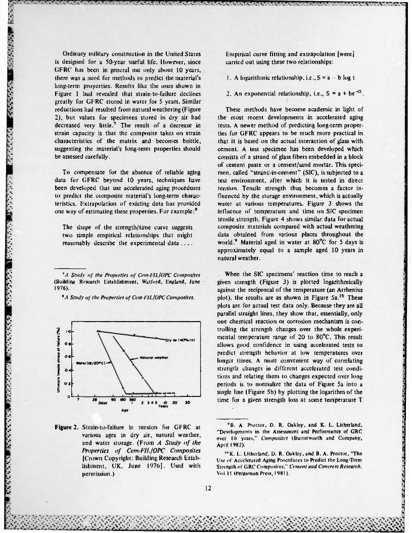
> Ordinary military construction in the United States is designed for a 50-ycar useful life. However, since GFRC lias been in general use only about 10 years, there was a need for methods to predict the material's long-term properties. Results like the ones shown in Figure 1 had revealed that strain-to-failurc declines greatly for GFRC stored in water for 5 years. Similar reductions had resulted from natural weathering (Figure 2), but values for specimens stored in dry air had decreased very little.7 The result of a decrease in strain capacity is that the composite takes on strain characteristics of the matrix and becomes brittle, suggesting the material's long-term properties should be assessed carefully.
To compensate for the absence of reliable aging data for GFRC beyond 10 years, techniques have been developed that use accelerated aging procedures to predict the composite material's long-term charac- teristics. Extrapolation of existing data has provided one way of estimating these properties. For example:8
The shape of the strength/time curve suggests two simple empirical relationships that might reasonably describe the experimental data ....
Empirical curve fitting and extrapolation [were] carried out using these two relationships:
1. A logarithmic relationship, i.e., S = a b log t
2. An exponential relationship, i.e., S = a + be"**.
These methods have become academic in light of the most recent developments in accelerated aging tests. A newer method of predicting long-term proper- ties for GFRC appears to be much more practical in that it is based on the actual interaction of glass with cement. A test specimen has been developed which consists of a strand of glass fibers embedded in a block of cement paste 01 a cement/sand mortar. This speci- men, called "stranc-in-cement" (SIC), is subjected to a test environment, .»fter which it is tested in direct tension. Tensile strength thus becomes a factor in- fluenced by the storage environment, which is actually water at various temperatures. Figure 3 shows the influence of lempcrature and time on SIC specimen tensile strength. Figure 4 shows similar data for actual composite materials compared with actual weathering data obtained from various places throughout the world.9 Material aged in water at 80°C for 5 days is approximately equal to a sample aged 10 years in natural weather.
M Stuffy of the Properties of Cem-FlL/OPC Composites (Building Research Establishment, Watford, England, June 1976).
'A Study of the Properties of Cembll./OPC Composites.
I • 0«
i 0. 1
1 »4-
I
Wot*rlW/20*C)
Of» «r (4CTW.rh>
When the SIC specimens' reaction time to reach a given strength (Figure 3) is plotted logarithmically against the reciprocal of the temperature (an Arrhenius plot), the results are as shown in Figure 5a.10 These plots arc for actual test data only. Because they are all parallel straight lines, they show that, essentially, only one chemical reaction or corrosion mechanism is con- trolling the strength changes over the whole experi- mental temperature range of 20 to 80°C. This result allows good confidence in using accelerated tests to predict strength behavior at low temperatures over longer times. A more convenient way of correlating strength changes in different accelerated test condi- tions and relating them to changes expected over long periods is to normalize the data of Figure 5a into a single line (Figure 5b) by plotting the logarithm of the time for a given strength loss at some temperature T
•
Figure 2. Strain-to-failure in tension for GFRC at various ages in dry air, natural weather, and water storage. (From A Study of the Properties of Cem-FII./OPC Composites [CroWM Copyright: Building Research listab- lishment. UK. June I976J. Used with permission.)
*B. A. Proctor, D. R. Oakley, and K. L. Lithertand, "Developments in the Assessment and Performance of GRC over 1Ü years." Composites (Butterworth and Company, April 1982).
"'K. 1.. Lithcrland. D. R. Oakley, and B. A. Proctor, "The Ilse ol Accelerated Agin)! Procedures to Predict the Long-Term Strength ol GRC Composites." Cement and Concrete Research. Vol II (Pergamon Press, 1981).
>
12
/> . >V- v-.-. A V.. /.•••/•••••••••/•••••/•,V,\r. •>j>j.SiV.V " N* V V' •••-Jj-t. a

.-'_'. ."-.".T-T! 1 .*» *» ^. f •»'«k1-. !'•. «u.,««..^-
I
I
U
««in« P«rio<« (dor«)
Figure 3. Cem-FIL 2 fiber strengths from SIC tests under accelerated aging conditions (in water at temperature indicated). (From B. A. Proctor, D. R. Oakley, and K. L. Litherland, "Developments in the Assessment and Per- formance of CRC Over 10 Years," Composites [Butterworth and Co., April 1982]. Used with permission.)
A«ln« P»n<jd (doy»)
Figure 4. Flexural strengths of GFRC composites after accelerated aging and weathering exposure (5 weight percent Cem-FIL 2 AR-glass fiber). (From B. A. Proctor, D. R. Oakley, and K. L. Litherland, "Development in the Assessment and Performance of GRC Over 10 Years," Composites [Butterworth and Co., April 1982]. Used with permission.)
I/T»I0»(V'>
A u •
•100- //•' <n //' t- i/' w Sc w / 1 / / /
HI > fa <
4 / / / w '*' IO " rT / «1 /
/ O SICRHULTS
/ • COMPOSmMCSULTl
i • y ' /
t / 30 32 3 4 3-6
(a) l/T x 10* (V1)
(b)
Figure 5. SIC specimen reaction time to a given strength, (a) Arrhenius plot; (b) normalized Arrhenius plot. (From K. L. Litherland, D. R. Oakley, and B. A. Proctor, "The Use of Accelerated Aging Procedures to Predict the Long-Term Strength of GRC Composites," Cement and Concrete Research, Vol 11 [Pergamon Press, 19811. Used with permission.)
13
•--% •-.•.- ±:l<<-\:-:- ••»•-
•:^;N-: •«,-
•'.*.'+-*.-j. •>:

VVATV-V'-'- '.•• '.• -.'ysLtJum >.-' 'v:-' •:' '.•» • .'..».i'.t'.y..«.?..v •.•.'••>'.- . V^.T'.V.'.^.'w^1 ..v *:".^ 7. „*. w/; •.V.T .v.»."
(relative to the time at some standard temperature) against l/T. This effectively combines and averages all the data for different strength levels (given in Figure 5a) into one overall picture of the relative acceleration of strength loss at different temperatures. A more detailed description of this analysis is in "The Use of Accelerated Aging Procedures to Predict the Long- Term Strength of GRC Composites.""
The significance of these tests and analyses is that initially, strength will decrease for a certain period, and then remain essentially constant in the long term. Other experiments have shown that the loss of strength in the falling region was not influenced by cycling between hot and cold, wet and dry. or hot, wet, and freezing conditions, but was governed mostly by time spent at the wet, elevated temperature.12 Figure 6 shows the change in strength with time for SIC speci- mens versus actual data for 10 years and the predicted response for 100 years and longer.I3 The fact that
" K. L. Litlicrlanii, D. R. Oakley, and B. A. Proctor. I3A. J. Aindow, D. R. Oakley, and B. A. Proctor, "Com-
parison of the Weather Behavior of GRC with Predictions Made from Accelerated Aging Tests," Cement and Concrete Research. Vol 14, No. 2 (Pergamon Press, March 1984).
IJA. J. Aindow, D. R. Oakley, and B. A. Proctor.
accelerated aging tests correlate so well with existing natural weathering data provides qualified confidence that CJFRC will perform satisfactorily up to 50 years and beyond. It also should be noted that a recent im- provement in the AR-glass fiber (now marketed as Cem-FIL 2 and Nippon Electric Glass AR2500H200) has changed the composite's aging characteristics from the standpoint that aging takes place more slowly. although the end results are similar when compared with those of the previous material (Figure 7).14 These data are from accelerated tests that represent 20 to 30 years of natural weathering.
This discussion has dealt with GFRC, however, the same results may apply to PGFRC. As stated earlier, polymer was added to protect the t-glass from attack by alkali in the cement. However, the long-term results were not as conclusive as originally expected. The U.S. panel manufacturers visited now recommend that AR-glass be used instead of E-glass.
The theory regarding protective mechanisms associa- ted with the addition of a water-dispersed polymer relates to the fact that the space between the fibers in a glass fiber bundle averages about 3 microns, whereas
l4B. A. Proctor, D. R. Oakley, and K. L. Litherland.
O o. 2
o
-40
-30
-20
-10
i o.
k* X +o
X oo
10 20 _l L_
60 100 _i l
.--.-.•-
Age in Years
Figure 6. Cem-FIL 2 GFRC strength retention in natural weather. United Kingdom (•). compared with predictions from accelerated-aging tests at 50°C (<>). 60°C (+). and 80°C (x). (From A. J. Aindow, D. R. Oakley, and B. A. Proctor, "Comparison of the Weather Behavior of GRC with Predictions Made from Accelerated Aging Tests." Cement and Concrete Research, Vol 14, No. 2 [Pergamon Press, March 1984]. Used with permission.)
14
.• V '.• .•;.• f V V '.-'.•".•*. • . r, .'.••. '. .'. <. <". r. <. -\ -\ •. -. •'. •'. --. -r, .-....-. «•. «-....•...•...•.•.•.•,..•. •
i^.

--*U."*-> i v.-> _->^>i-.j-^-roE-xi^-v'.-vrv jvg-.xv.-.--*wrv.i ^A/t/!^jdvw^; .^ u,m. .L.-VJ-.H..^.,* ^-TJT.^
r-
i
E
5 P
l«0
Ooy» in »ottr at 90* C
Figure 7. Retention of strain-to-failure in bending for Cem-FIL 1 and Cem-FIL 2 CRC composites (5 weight percent) in accelerated tests of 50°C (c = Cem-FIL 1 fiber; • = Cem-FIL 2 fiber). Note: 180 days is equal to about ISO years of natural aging. (From B. A. Proctor, D. R. Oakley, and K. L. Litherland, "Developments in the Assessment and Performance of CRC Over 10 Years," Composites [Butterworth and Co., April 1982]. Used with permission.)
the smallest cement particles average about 30 microns.15 Therefore, the space between the fibers does not fill with cementitous material. Eventually, this space becomes filled with cement hydration products (e.g., calcium hydroxide) which, though not as hard as glass, are suspected of notching the fiber's surface when placed under load. If this happens, the glass, which is very notch-sensitive, would lose con- siderable tensile strength; this would, in turn, reduce the composite strength. However, when polymer is added to the mix, the particles, being only 0.1 to 1.5 microns in diameter, can fill the interstices between filaments in a glass fiber bundle. This not only pre- vents the formation of hydration products, but also provides a matrix between the fibers that is soft enough to preclude mechanical degradation under load, assist in the load transfer between fibers, and help protect the fibers from alkali attack. Figure 8 shows results of accelerated-aging bending tests on H-glass CFRC with and without polymer.14
Figure 9 compares the effect on bending strength of specimens containing E -glass and 15 percent poly-
" M. J. N. Jacob», FORTON P(i/iC A Many-Sided Material (Depurtmem »t Material Application Development DSM- Conuol Laboratory, Gcleen, The Netherlands, October 1981).
'*M. J.N.Jacobs.
15
» ' « • • • . * • " >>.-.• \\VV v-v
25
20-
15-
10
• timt (month«)
0.5 I 12 24 36
Figure 8. Results of accelerated aging bending test on E-glass mixes with and without polymer. (From M. J. N. Jacobs, FORTON PGRC- A Many-Sided Material [Department of Material Application Development DSM- Control Laboratory, Geleen, The Nether- lands, October 1981] .Used with permission.)
mer (FORTON) with AR-glass mixes containing no polymer. Whether PGFRC's better performance is a result of the polymer protecting the E-glass or just an improvement in the matrix properties due to the poly- mer is still a subject of debate. Similar results were obtained for accelerated aged tensile strength and strain at UTS.17
Other benefits attributed to the use of a polymer include lower water absorption, reduced drying shrink- age and thus less cracking and crazing, higher 28-day MOR, and better overall performance in the aged state. Perhaps the most practical benefit claimed for the PGFRC is the absence of curing requirements."
"J. Bijen, "Durability of Some Glass Fiber Reinforced Cement Composites," AC1 Journal, Paper title No. 80-30 (American Concrete lnst . July-August 1983).
"J. I. Daniel and M. E. Pecoraro, Effect of FORTON Polymers on Curing Requirements of AR (Vlass Fiber Re- inforced Cement Composites (Construction Technology Laboratories, Portland Cement Association, Skokie, 1L, October. 1982); H. P. Ball, i'., The Effect of FORTON Com- pound on (JFRC Curing Requirements (Biii Consulting Ltd., Ambridge, PA).
^>>^.\\N^yiV:vv.fr\^^ •"• •*• •*«.-*- *V- <• •*. <\ J
.v.-v :--;>^;;Xy:^

rT^F»T» \ •.'." •'.".'. ' •'•• ' " " ""• '• ' •*'* I * T?^'r« :^ .** ?« ".^ .•* '-••• -w^ ?v.i. >.-* •.-» •.-» •-•» .-»i
z • w 1 s
7300-
•ooo- 40.
4900-
HWM Forttft(P)QFftC Zt OATS 20*C (M*F) 65% R H Aft-OFftcroAvs 2o«c («a*F) 65% RH
»OATS 20*C(eS*Ft 65% RH
WOO JO.
1500
Figure 9. Bending strength development under ac- celerated aging at 50°C under water. (From J. Bijcn, "Durability of Sonic Glass Fiber Reinforced Cement Composites," AC/ Jour- nal, Paper Title No. 80-20 [American Con- crete Inst., July-August 1983). Used with permission.)
GFRC design is based on the assumption that the aged MOR does not drop below the 28-day LOP. To obtain this property, it usually is recommended that the material be wet-cured for 7 days. However, tests have shown that by adding 5 volume percent polymer, the requirement can be met without wet-curing. Figure 10 shows the results of curing tests conducted by the Portland Cement Association on AR-glass specimens."
The data show that composites containing at least 5.0 percent solids by volume develop 28-day LOP strengths equal to or slightly greater than similar composites containing no polymer and subjected to 7-day moist cure. This result indicates that, for LOP development, the recommended 7-day moist-curing period for AR-GFRC panels can be avoided by adding at least 5.0 percent FORTON polymer solids by volume.
"J. I. Daniel and M. E. Pccoraro; H. P. Ball. Jr.
16
.*- f-.
LONG TERM EVALUATION OF GFRC INSTALLATIONS
As part of an ongoing program to assess the in- service performance of building materials and com- ponents, the BRI studied, from a structural perform- ance aspect, GFRC paneling that had been in service in the United Kingdom for 5 to 7 years.20 The in- spections included visual examination to determine the incidence of cracking, movement, water penetra- tion, displacement of sealants, and color and compass orientation of panels. Thirty-five major sites together with 25 smaller sites, some with single-skin cladding, were inspected. Seven housing sites in Scotland with 95,000 in2 of single-skin cladding also were inspected. It should be pointed out that none of these installa- tions used the metal stud backup with the highly flexible "L" anchor used in the United States (see Chapter 4). The results showed:21
There were no signs of cracking at 10 of the major sites. Of the remainder, there was in- cipient cracking at two sites, there was cracking of some panels at 10 sites, minor repair of cracking had been carried out at seven sites, major repair or partial replacement had been carried out at five sites, and all the cladding had been replaced at one site.
More cracks in cladding on individual buildings were observed on south- and west-facing panels than on other aspects.... In some cases joint sealants were partially detached. Bowing of large and small panels was observed at a few sites.
Cracks were observed in single-skin cladding panels at two sites in England, at one of which (he panels were located internally. No cracks were observed in single-skin panels in Scotland.
The cracking represented a potential safety hazard at only one site; here remedial action was taken to prevent detachment of cracked parts. Reports were received on practice and experience from Holland. Japan, South Afi-ca and the United States of America, which provide a range of climatic conditions different from those of the United Kingdom.
"J.I . A. Moore.
' M . A. Moore.
v.v.v.v. &£&£tä

r •*".•-»:-» . • .", ••* •-:•- •- :-J »J.-HT
i
!
•SOOr
IQOO
SOO
X.-axm*
o - 3 5% Fbfto« «»ir*w SOIIO» Br Volumn a — SO*. a 7.9% o —• — ».0% +• X —— — 0% Forion, t-*0» MvtMCur« • MI*re» MP«
o i 3 A»*,e»y*
Figure 10. Results of curing tests on AR-glass specimens-LOP versus age. (From J. I. Daniel and M. E. Pecoraio, Effect ofFORTON Polymers on Curing Requirements ofAR-Glass Fiber Reinforced Cement Composites [Construction Technology Laboratories, Portland Cement Association, Skokie, IL, October 1982]. Used with permission.)
In Japan and the United States of America, single-skin cladding predominates. Experience is limited to about 8 years, with no reports of significant cracking. The experience with sand- wich panels in Holland and South Africa appears to be similar.
Practice in the design, construction and use of landwich panels in South Africa appears to be broadly similar to that in the United Kingdom, although skin thicknesses and glass fibre contents may be marginally lower, overall thicknesses seldom exceed 100 mm and panels are generally flat, of limited area and produced by mechanical methods.
Experience of large flat sandwich panels in Holland appears to have been satisfactory. The cement is likely to have properties different from those of the ordinary Portland cement usually used in the United Kingdom.
GFRC cladding panels in service in the United Kingdom show that an unacceptably high pro- portion of buildings inspected had some cracked panels. Investigations revealed that design pro- cedures have not always adequately taken account of all the relevant factors and uncertain- ties, and that deficiencies in manufacture and installation luve contributed in some cases to poor performance. In particular, the contribution which moisture and thermal effects, and internal
17
»8gsasg^^

.-•.-V-.-K-;>v -.%•;•% •.-•••^V^ 'A7- .>".-• >.^ A J* •«•v\~u ."- ••-? .-• .'••• .'J •••- .-- 'A Lv.^ •.-
and external restraints, may make to inducing tensile strains in the GFRC have not been recognized sufficiently in relation to its ability to resist cracking.
Some calculations for certain types of plain sandwich panels suggest that allowance for the worst combinations of wind loads, thermal and moisture movements, and internal restraints can only just be accommodated with a suitably factored long-term tensile strength capacity.
The additional considerations posed by a long- term reduction in strain capacity have not always been fully appreciated.
Any additional restraint from connections could easily erode the margin not only in the factored strain capacity but also in the ultimate strain capacity and therefore cause cracking in panels containing even good-quality GFRC.
It appears that cracking in recently installed panels can be explained only by gross short- comings in restraint or quality of manufacture.
A wide variability in susceptibility of individual panels to cracking would be expected for panels of any age, even if of uniform quality, because the loading and exposure conditions will differ, the restraint imposed by any imperfect fixing is unpredictable and the actual strain capacity, even of good-quality material, is variable and will differ from that assumed in design by an indeterminate amount.
The BKI study has shown that the greatest contri- buting factor to U.K. failures apparently has been the connections' inability to accommodate the large panel movements due to temperature variations and moisture absorption. The use of sandwich panels together with their shape and size also appears to contribute. Design- ers apparently underestimated and failed to provide for the magnitude of movement. As described in the next chapter, present U.S. practice avoids this problem.
A similar study of GFRC panels in the United Kingdom and other Furopean countries was carried out by Pilkington Brothers and Fiberglass Limited.22
The investigation involved: the incidence of GFRC architectural cladding in I urope; the causes of these
'dm III. Inliirmalinn Bulletin. Nn.44 «July 1983).
problems; the analysis of stresses in sandwich panels: and material properties and weathering behavior of GFRC. The study concluded that:
1. Nearly all cracking was caused by the restraint of drying shrinkage of GFRC -possibly accentuated by thermal strain differentials.
2. Most problems resulted from the use of rigid, overtightened, and/or multipoint fixings—or from restraint due to the inherent rigidity of particular shapes of sandwich panels.
3. Significant contributory factors were poor GFRC material quality, poor manufacturing practice, and damage in dcmolding and handling.
4. The incidence of cracking was significantly high- er for large sandwich panels that consist of the sequence composite PBAC (polystyrene bead aggregate con- crete) polystyrene-PBAC cores and also for dark- colored panels.
5. Careful reassessment of previous and new data from actual weathering confirms that the long-term strength behavior of GFRC is closely in line with previously published data. There is no suggestion that cracking was due to unexpected material deterioration or that the strength values recommended for design were incorrect.
The seven U.S. installations visited for this study had no cracks, though one had a considerable amount of minor cra/ing. All were single-skin panels, primarily with steel stud framing backup. Three failures have been reported (by word of mouth) in the United States; two appeared to be due to faulty manufacturing procedures and the other to building attachments that did not accommodate enough movement by the panels from temperature and moisture migration.
Information from the sources cited in Chapters 2 and 3 was used to develop design criteria that could apply to GFRC used in military construction. These criteria are explained in the appendix.
PANEL PRODUCTION AND PRACTICE IN THE UNITED STATES
Five panel manufacturers and a GFRC consultant were visited. Two operate in the northwest, two in
18
^.•-•.-••.-.wv.'. n
AVV V.V >>•:.
tV>V L^\Vi.v>\NV,v,;r:vL-.^v\v^

•*•'-"» .Tr.'.-\iT.ni\".':A".v," V^"*.' *." <• H." *:* «T •!.* '-—5.-
Central United States, and one in the south central part of the country. All five manufacture panels using AR-glass fibers and two use 5 to 7 volume percent polymer (FORTON). Both silica sand and fine ordinary sand are used in combination with either white or ordinary Portland cement. Manufacturers who do not use a polymer use a sand/cement ratio of 0.20:0.30; those adding a polymer use as high as a 1:1 ratio. The most widely used mix design is reported to be a 0.5 sand/cement ratio with 5 volume percent polymer.
Panels are designed for self-loading only, with no other superimposed structural loads permitted. Wind loads are accounted for, but these are relatively minor when the steel stud frame is used (Figure 11). Studs usually are spaced at 0.61 m. The "L"-shaped con- nector shown in Figure 12 and described below ac- commodates the large panel movement due to temp- erature and moisture absorption. The steel stud frame and "L" connectors have simplified panel design considerably.
All five plants had similar production processes, using what could be called "standard" procedures. All had excellent production facilities, with two able to produce over 322 m2 sq ft of panel per work day. All were operated by persons experienced in producing GFRC (5 to 10 years) in particular and concrete in general. All understood the importance of quality control, and each plant had a small laboratory for conducting bending tests, fiber-count tests, and others on a regular schedule. All of the plants are producing panels with the steel stud backing, rather than using built-up ribs (Figure 13) as was the original procedure.
sheets. Minor premixing and casting are done when necessary. Each plant has well equipped metal- fabrication and wood-framing shops. Production in all five plants consists of single-skin panels 10 to 13 mm thick with approximately 5 weight percent fiber. Sandwich panels are not a routine production item, being made only for special applications. In general, panels smaller than those ordinarily used in the United Kingdom are used in the United States. Seldom do the U.S. panels exceed 18.6 m2 in size. When they are made, sandwich panels are kept flat and less than 5.6 m2.
As already stated, two plants cure their panels by adding 5 to 7 volume percent polymer to the mix. The other plants use wet-curing, but only when it is necessary to do so. Otherwise, panels usually are cured by storing outside before shipping. Membrane-curing also is used at times. Because the panels are very light- weight, running 29 to 73 kg/m2, shipping costs are low and all of the manufacturers said they could compete by shipping up to 1609 km.
The manufacture of GFRC panels by the companies visited is a very sophisticated operation, comparable to any good precast concrete plant. These manufactur- ers have developed basic techniques into production procedures that result in a consistently uniform prod- uct, high in quality and using to the fullest the great versatility of the material. Figures 14 through 16 are typical examples of GFRC projects in the United States.
1 a
-~
i
An important recent development, in addition to the use of steel stud framing as backup, was the intro- duction of the "L"-shaped anchor for attaching the panel to the steel frame. The anchor is a 10-mm round rod, bent into the shape of an "L." One leg is attached to the panel with GFRC before the panel has set up. A bond beaker is used on the rod so the connection can accommodate large movement. The other leg is welded to the steel stud frame using only about 25 mm at the very end of the leg, thus avoiding a rigid attach- ment and allowing for large movement if necessary. The frame is then attached to the building structural frame, but the panel has been more or less isolated from movement by the building and is free to move on its own.
The hand spray-up method is the predominant one used in manufacturing panels; however, several companies can machine-spray flat and corrugated
CONCLUSIONS AND RECOMMENDATIONS
The following conclusions are based on information obtained from the literature, visits to installation sites and manufacturing plants, and interviews with the developers and producers of GFRC.
1. GFRC panels and other products have been wide- ly used throughout the world since 1974.
2. Failures of GFRC panels have occurred mainly in the United Kingdom. The main cause of the failures is attributed to the panel connections' inability to accommodate the large movement associated with temperature and moisture, especially in large profiled sandwich panels.
5
:••
-
19
• > -*• .*«• .•».-». -' »> .-. • •*•-*• ."• »Y-> -•-."*• ."»'
^±Jt. >: •V.V-- v^afr-y 'J.X.
.-.,
.--".

^» "'•"•IM"|il «^^•pil^l^OTi^^ppVTVTVTVpwrvT^l1.* m f • I! • I >
Figure 11. Typical steel stud framing used in the United States.
Figure 12. "L"-shaped anchor used to secure panels to the steel frame. One leg of the "L" is buried in the panel.
20
v.v.v.v..%v yL-Lfi ' » '.- * - • - * t * m •> »>% • • « " - » " _ •, • ' ft.-«-*-»-*-»- •• V-'J

—7—y •^„••.V-*. '-'..'.'J..•:•!•.• >.y, i".1^ •,•..•: ^.-'.'J.'y.'P. ' ^.'TT^TT^IT '. -. '.".» '.^'*. r ^^^^^r^v* i : • i» .•- i • - - . • -.
•.
:*^ r
Figure 13. Panels with built-up ribs as stiffeners.
Figure 14. GFRC use on a bank building in Dallas. TX.
21
• ••-••-•••----•-•-••-•
.-»»-- .•»,
• . • .. % _. ---- - - Ji -r -* -J -

'.•*• •.*• i* 'JV.TA 'A 11 vi 'A A i:m!v*. :^.:v.Km.v.'.m.^yr*.msm.rrjr».••.»• » • » T ' •• ' •••-»•- '"." \* '." ••* -.".-." -."i •.' •.' -.' '-."
Figure IS. Hotel facade in Seattle, WA.
Figure 16. Office building in Nashville, TN.
22
.-V- .%J.N.-"

'V?.->.-A-_*. • —•—. • "• '.'< r?:'_'. • • "'• " "~I•^^•^•^<^»•T• '.'? v»T?.* '.w " :^. i m A .v.. v.^1 ».-v ».* <•• *• »•• !• i" y »1
J. Two AR-glass fibers are available in the United States the Nippon blectric Glass Company, Ltd., fibers and the Pilkington Brothers, Ltd., fibers. The Pilkington second-generation AR-glass (Cem-FIL 2) has replaced Cem-FIL i throughout the United States.
4. Failures due to the material made with Cem- FIL 2 are relatively few and reportedly are a result of poor manufacturing procedures, not inherent material deficiencies. All other failed panels discussed in this report used Cem-FIL 1 fibers.
5. The GFRC panel industry in the United States is thriving and capable of providing a continuous supply at any location in the country.
6. Design and manufacturing procedures relatively standard throughout the United States.
are
7. The use of the steel stud frame and "L"-shaped anchors in the United States has overcome the defic- iencies in design and construction that contributed to failures in the United Kingdom.
8. The addition of 5 percent or more of a polymer to the GFRC mix eliminates the need for other forms of curing.
9. A reliable accelerated-aging test procedure has been developed to predict long-term durability of GFRC. The procedure has been verified by comparison with existing data.
Based on these conclusions, it is recommended that GFRC panels be used in military construction. Since the material itself is simply a reinforced Portland cement mortar, for whwh long-term durability and properties are well understood, there should be no problems from a materials standpoint when panels are designed to take into account the long-term properties. Also, it now appears that factors which have contributed to failures are well understood and accounted for in present design and construction practices; the vast number of successful projects world- wide attest to this.
Criteria for using this material are given in the appendix.
REFERENCES
A Study of the Properties of Cem-FIL jOPCComposites (Building Research Establishment, Watford, England, June 1976).
Aindow, A. J., D. R. Oakley, and B. A. Proctor, "Comparison of the Weather Behavior of CRC with Predictions Made from Accelerated Aging Tests," Cement and Concrete Research, Vol 14, No. 2 (Pergamon Press, March 1984).
Ball. H. P.. Jr.. We Effect of FORTON Compound on GFRC Curing Requirements (Ball Consulting Ltd.. Ambridge.PA).
Bijen. J., "Durability of Some Glass Fiber Reinforced Cement Composites," AC! Journal, Paper Title No. 80-30 (American Concrete Inst., July-August 1983).
Bijen, J., "E-Glass Fibre Reinforced Polymer Modified Cement," Proceedings, International Congress on Glass Fibre Reinforced Cement, London, Ontario, 1979 (Glass Fibre Reinforced Cement Association. Bucks. 1980).
Cem-FIL Information Bulletin, No. 44 (July 1983).
Daniel, J. I., and M. E. Percoraro, Effect of FORTON Polymers on Curing Requirements of AR-Glass Fiber Reinforced Cement Composites (Construc- tion Technology Laboratories, Portland Cement Association, Skokie, IL, October 1982).
Forton, B. V., FORTON Polymer-Modified Glass Fibre-Reinforced Cement: A New Freedom in Building Design (Sittard Holland).
Jacobs, M. J. N., FORTON PGRC-A Many-Sided Material (Department of the Material Application Development DSM-Control Laboratory. Geleen. The Netherlands. October 1981).
Lithcrtand, K. L.. D. R. Oakley, and B. A. Proctor, "The Use of Accelerated Aging Procedures to Predict the Long-Term Strength of GRC Com- posites," Cement and Concrete Research, Vol 11 (Pergamon Press. 1981).
23
• •

•?: r.'i" ••• .- J- •-- IVT'^'
Majumdar, A. J.. and V. Laws. "Composite Materials Based on Cement Matrices." Phil. Trans. R. Soc. London, A310 (1983).
Majumdar. A. J.. and J. F. Ryder. "Glass-Fibre Re- inforcement of Cement Products," Glass Technol- ogy. Vol «. No. 3 (June 1968).
Moore, J. F. A., The Use of Glass-Reinforced Cement in Cladding Panels (Building Research Establish- ment. Watford. England, 1984).
Pilkington Brothers. Ltd.. Cem-Fll. GRC Technical Data Bulletin (St. Helens. Mcrscysidc, England).
Poole. A. B. (Ed.). "The Effect of Alkalies on the Properties of Concrete," Symposium Proceedings (Cement and Concrete Association. September 1976).
Proctor. B. A., D. R. OakJey. and K. L. Litherland. "Developments in the Assessment and Perform- ance of GRC over 10 Years," Composites (Butter- worth and Company, April 1982).
Properties of GRC: Ten Year Results (Building Research Establishment, Watford, England, Nov- ember 1979).
24
:.• :•: &&L&2&2&*. .iviviv:
."•' ."• ."•.'. ."-.."•-• 'T•.";,.^- *^_^' V'.V •. "'. ».' ^. .-J.^. I'.IT. •^J.^L.^,1^ •
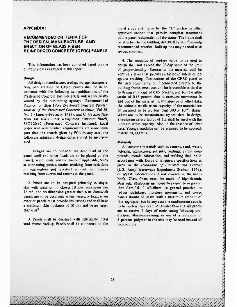
APPENDIX:
RECOMMENDED CRITERIA FOR THE DESIGN. MANUFACTURE, AND ERECTION OF GLASS FIBER REINFORCED CONCRETE (GFRC) PANELS
metal studs and frame by the "L" anchor or other approved anchor that permits complete movement of the panel independent of the frame. The frame shall be attached to the building structural sy^em following recommended practice. Built-up ribs m.\y be used with special approval.
This information has been compiled based on the durability data examined in this report.
Design All design, manufacture, testing, storage, transporta-
tion and erection of GFRC panels shall be in ac- cordance with the following two publications of the Prestressed Concrete Institute (PCI), unless specifically waived by the contracting agency: "Recommended Practice for Glass Fiber Reinforced Concrete Panels," Journal of the Prestressed Concrete Institute, Vol 26, No. 1 (January-February 1981); and Guide Specifica- tions for Glass Fiber Reinforced Concrete Panels, SPC-120-82 (Prestressed Concrete Institute). Local codes will govern when requirements are more strin- gent than the criteria given by PCI. In any case, the following minimum design criteria must be incorpor- ated.
1. Designs are to consider the dead load of the panel itself (no other loads are to be placed on the panel), wind loads, seismic loads if applicable, loads at connecting points, strains resulting from variations in temperature and moisture content, and strains resulting from curves and returns in the panel.
2. Panels are to be designed primarily as single- skin with minimum thickness 10 mm, maximum size 18 m2, and no dimension greater than 6 m. Sandwich panels are to be used only when necessary (e.g., when exterior panels must provide insulation) and shall have a minimum skin thickness of 10 mm and be no larger than 6 m2.
3. Panels shall be designed with light-gauge metal stud frame backup. Panels shall be connected to the
4. The modulus of rupture value to be used in design shall not exceed the 28-day value of the limit of proportionality. Stresses in the material shall be kept at a level that provides a factor of safety of 2.5 against cracking. Connections of the GFRC panel to the steel stud frame, or if connected directly to the building frame, must account for irreversible strain due to drying shrinkage of 0.05 percent, and for reversible strain of 0.15 percent due to moisture movement in and out of the material. In the absence of other data, the ultimate tensile strain capacity of the material can be assumed to be no less than 300 X 10"*. Higher values are to be substantiated by test data. In design, a minimum safety factor of 1.8 shall be used with the ultimate strain capacity. Also, in the absence of other data. Young's modulus can be assumed to be approxi- mately 20,000 MPa.
Materials All concrete materials such as cement, sand, water,
coloring, admixtures, sealants, coatings, curing com- pounds, metals, fabrication, and welding shall be in accordance with Corps of Engineers specifications as given in the Handbook of Concrete and Cement (U.S. Army Waterways Experiment Station, 1949), or ASTM specifications if not covered in the hand- book. Glass fibers must be made of high-zirconia glass with alkali-resistant properties equal to or greater than Cem-FIL 2 AR-fibers. In general practice, to reduce shrinkage, moisture movement, and creep, panels should be made with a maximum amount of fine aggregate, but in any case the sand/cement ratio is to be no less than 0.25 nor greater than 1.0. All panels are to receive 7 days of moist-curing following pro- duction. Membrane-curing or use of a minimum of 5 percent polymer in the mix may be used instead of moist-curing.
25
v.y.v.v.v;.f.v^-.-;-.-::.v.,.\-.\ ••• ••• •-.\.-.>.y.'.-.v.y.y v'vV,
r .-

«• "r ~. • "\T .V* \v '1'4\.V "J^l-V-i
USA-CERL DISTRIBUTION
uhi.r <lf lfl|LH«tri
ATTNl DAEN-RE-D ATTHl UAEN-AS1-L ATTN: UAEH-CCP ATTHl DAtN-CW ATTN: UAEH-CWE ATTMi DAEN-CUM-H AT«: OAEN-CUU ATTH: DAEH-CVP ATTNs OAEN-EC ATTHi DAEH-ECC ATTN: DAEN-ECE ATTNl DAEH-ECB ATTN: DAEH-ED ATTN: DAEN-IOC ATTN: DAEH-BDM ATTN: DAEN-RH ATTN: DAEN-ZCE ATTNl OAEN-ZCr ATTN: DAEN-ZCl ATTNl DAEN-ZCM ATTN: OAEN-ZCZ
(1)
rtSA, ATTN: Library 22060 ATTN: DET III 79906
US Any Engineer Dletrlcto ATTNl Library (Al)
US Any Engineer DlvUlone ATTN: Library (14)
US Aray Europa AEAEH-ODCS/Engr 0940) ISAE 09081 V Corp»
ATTN: DEN (11) VII Corp.
ATTNl DIH (IS) 2 1 at Support Command
ATTNl DIM (12) USA BariIn
ATTNl DIH (11) USASETAF
ATTNl DEN (10) Al Had Coeauad Europa (ACE)
ATTN: DEN ())
Sth USA, Korea (19)
BOK/US Coablned Forcen Co—and 96)01 ATTN: EUSA-HHC-CFC/Engr
USA Japan (UBABJ) ATTNl AJEN-DEH 96)4) ATTNl DEM-Honahu 96)4) ATTNl DEH-Oklnewe 96))1
4l6th Eaglnaar Coaaand 6062) ATTNi facllltlaa Engineer
US Military Acadaay 10966 ATTNi Facllltiaa Englnaar ATTN: Oapt of Caography 4
Coaputar Sclasca ATTNl DSCFEB/NAIN-A
AHMBC, ATTN DtXMR-WE 02172
USA AUC0M 61299 ATTNl 0BCIS-BI-I ATTNl DBSAB-IS
ANC - Dir., Inet., 4 Serve ATTNl DEH (2))
DLA ATTN: DLA-Wl 22)14
DNA ATTNl NADS 20)0)
FOBICOM FOBSCOH Engr, ATTNi AFEH-DEH ATTN: DEH (2))
1NSC0M - Ch, Inatl. Olv ATTNi Paellltlaa Eaglnaar ())
HDH, ATTNl DEH ())
NTMC ATTNi HTHC-SA 20)1) ATTNi Paellltlaa Eaglnaar ())
MA1ADCOM, ATTN: DEDNA-r 01760
TABCOM, Fac. Dlv. 4S090
TBADOC HQ, TBADOC, ATTNl ATEN-DEH ATTNl DE! (19)
TSABCOM, ATTNl 3TSAS-F 6)120
USACC, ATTNi Paellltlaa Eagr (2)
WESTCOM ATTNl DEH, Ft, Shaftar 96858 ATTNl APEN-IM
SHAPE 09055 ATTNl Sur». Saetloa, CCB-OPS
Iafreetructure Braaeh,
HQ USHUCOM 09128 ATTNl EU 4/7-LOE
Fort Balvolr, VA 22070 (7) ATTNl Canadian Llalaon Offlee ATTNl Water teeourcee Support Ctr ATTNl Eagr Studie. Center ATTNl Eagr Topographie Lab. ATTHl ATZA-DTE-SU ATTNl ATZA-DTE-En ATTNl B6D Coaaand
CUIL, ATTNl Library 0)755
WIS, ATTNl Library 391BO
HQ, XVIII Airbora Corp. •ad Fort Bragg
ATTNl AFZA-rE-EE 28)07
Araa Eaglnaar, AEDC-Aree Offlea Arnold Air Forea Station, TN )7)I9
Chaauta ATB, IL 6186t 33*5 CBS/DE, Stop 27
Norton ATI, CA 92409 ATTNi AFECE-MX/DEE
HAVPAC ATTNi Englnaarlng Coaaand (7) ATTNi Dlvlalon Offlcaa (6) ATTN: Haval Public Werke Cantar (9) ATTNi Haval School, Morall Library ATTHi Haval Clvtl tngr Üb. ())
HCEL ATTNl Library, Coda L08A 9)041
Dafanaa Tachntcal Info. Cantar 22)14 ATTNi DDA (12)
gngr toclettaa Library, NY 10017
Natl Guard Bureau Inatl, Dlv 20)10
US Covt Printing Offlea 22)04 Bacalvlng Saet/Dapoaltory Coplaa (2)
US Any Env. lyglaaa Agency ATTNl HSNB-E 21010
National Bureau of Staadarde 20760
•MC ATTN: HSLO-F 782)4 ATTNi Faellltlea Englaaar
plteetawne ANC 80240 Walter Bead AHC 20012
))i 03/22/85
^^/^X^^v^^v,-.^,,...,/ Biät a*i*
* V.v "j—.*. j^tTia-, ,rf-„ j-_
CMC Taani Distribution
Chief of Engineers 20314 AHN: DAEN-ZCF-B ATTN: DAEN-ECZ-A AHN: DAEN-EC8 (2) AHM: DAEN-ZCP
US An*/ Engineer District New York 10007
ATTN: Chief, Design Br Pittsburgh 15222
ATTN: Chief, 0RPC0 ATTN: Chief, Engr Dlv
Philadelphia 19106 ATTN: Chief, NAPEN-0
Baltimore 21203 ATTN: Chief, Engr 01v
Norfolk 23510 ATTN: Chief, NAOEN-M ATTN: Chief. NAOEN-0
Huntington 25721 ATTN: Chief. ORHED-F
Wilmington 28401 ATTN: Chief. SAWCO-C ATTN: Chief. SAWEN-D
Charleston 29402 ATTN: Chief. Engr Dlv
Savannah 31402 ATTN: Chief, SASAS-L
Jacksonville 32232 AHN: Const 01*
Mobile 36628 ATTN: Chief, SAMEN-0 ATTN: Chief. SAMEN-F ATTN: Chief. SAMEN
Nashville 37202 ATTN: Chief. ORNED-F
Memphis 38103 ATTN: Chief, Const Dlv ATTN: CMef, IMMED-O
Vlcksburg 39180 ATTN: Chief, Engr Dlv
Louisville 40201 ATTN: Chief. Engr Ofv
Detroit 48231 ATTN: Chief, NCEED-T
St. Paul 55101 ATTN: Chief, EO-O ATTN: Chief. EO-F
Chicago 60604 AHN: Chief. NCCCO-C ATTN: Chief, NCCtO-F
Rock Island 61201 ATTN: Chief. Engr Dlv ATTN: Chief, NCRED-F
St. Louis 63101 ATTN: Chief, EO-O
Kansas City 64106 ATTN: Chief. Engr Dlv
Oman« 68102 AHN: Chief, Engr 01*
New Orleans 70160 ATTN: Chief. LMNED-DG
Little Rock 42203 ATTN: Chief. Engr Dlv
Tulsa 74102 ATTN: Chief, Engr 01»
Ft. Worth 76102 ATTN: Chief. SUFED-0 ATTN: Chief. SWFEO-F
Galveston 77550 ATTN: Chief. SWGAS-L ATTN: Chief, SWGCO-C ATTN: Chief, SWGED-DC
Albuquerque 87103 ATTN: Chief, Engr D1v
Los Angeles 90053 ATTN: Chief, SPLED-F
San Francisco 94105 AHN: Chief, Engr Olv
Sacramento 95814 AHN: Chief. SPKEO-O ATTN: Chief. SPKCO-C
Far East. 96301 AHN: Chief. Engr 01 v
US Amy Engineer District Portland 97208
ATTN: Chief, 08-6 AHN: Chief, FM-I AHN: Chief, FM-2
Seattle 98124 AHN: Chief, NPSCO AHN: Chief. NPSEN-FM ATTN: Chief, EN-OB-ST
Walla Walla 99362 ATTN: Chief, Engr Olv
Alaska 99501 ATTN: Chief. NPASA-R
US Army Engineer Division New England 02154
ATTN: Chief. NEDEO-T AHN: Laboratory AHN: Chief. NEOCO
Middle East (Rear) 22601 ATTN: Chief. MCOEO-T
North Atlantic 10007 ATTN: Chief, NAOEN
South Atlantic 30303 ATTN: Laboratory ATTN: Chief. SADEN-TC ATTN: Chief, SADEN-TS
Hunstvllle 35807 ATTN: Chief, HNDED-CS ATTN: CMef, HNOED-M AHN: Chief. HHOEO-SR
Lower Mississippi 39180 ATTN: Chief, LMVED-G
Ohio River 45201 AHN: Laboratory ATTN: Chief, Engr 01»
Missouri River 66101 ATTN: Chief. MRDED-G ATTN: Laboratory
Southwestern 75202 ATTN: Laboratory ATTN: Chief. SUOEO-MA ATTN: Wf, SWDED-TG
South Pacific 94111 ATTN: Laboratory
Pacific Mean 9S858 ATTN: Chief. Engr Dlv ATTN: FMS Branch ATTN: Chief. POOED-0
North Pacific 97208 ATTN: Laboratory ATTN: Chief. Engr 01v
6th US Army 94129 ATTN: AFKC-EN
7th US Army 09407 ATTN: AETTM-HRD-EHO
HQ, Combined Field Army (ROK/US) ATTN: CFAR-EN
HQOA SGRD-EDE 20314
US Army Foreign Science and Tech Center
ATTN: Charlottesvllle, VA 22901 ATTN: Far East Office 96328
USA ARRADCOM 07801 ATTN: OROAR-LCA-OK
HO, USAMROC AHN: S6RD-PLC Fort DetHck, MD 21701
West Point, NY 10996 ATTN: Oept of Mechanics ATTN: Library
Ft. Belvolr, VA 22060 ATTN: ATSE-TD-TL (2) ATTN: Learning Resource Center ATTN: British Liaison Officer (5)
Ft. Benning, GA 31905 AHN: ATZB-FE-EP AHN: ATZB-FE-BG
Ft. Clayton Canal Zone 34004 ATTN: OFAE
Ft. Leavenworth, KS 66027 ATTN: ATZLCA-SA
Ft. Lee, VA 23801 ATTN: DRXMC-D (2)
Ft. McPherson, GA 30330 ATTN: AFEN-CD
Ft. Monroe, VA 23651 ATTN: ATEN-AD (3) ATTN: ATEN-FE-ME AHN: ATEN-FE-EN (2)
Ft. Richardson, AK 99505 ATTN: AFZT-FE-E
Rocky Mountain Arsenal 80022 ATTN: SARRM-CO-FEP
USA-WES 39180 ATTN: C/Structurts ATTN: Soils I Pavements Lab
Naval Facilities Engr Command 22332 ATTN: Code 04 AHN: Code 2013 C
Port Huenemt, CA 93043 ATTN: More11 Library
Commander (Code 2636) 93555 Naval Weapons Center
Boiling AFB, DC 20332 AF/LEEEU
Little Rock AFB ATTN: 314/OEEE
Patrick AFB, FL 32925 ATTN: XRQ
Tinker AFB, OK 73145 2854 ABG/DEEE
Tyndell AFB, FL 32403 AFESC/TST
Airports and Const Services 01r 96358 Technical Info Reference Center
Ottawa, Ontario. Canada K1A QMS
Bldg Research Advisory Board 20418
Oept of Transportation Library 20590 Transportation Research Board 20418
Division of Bundling Research National Research Council Ottawa, Ontario, Canada K1A 0R6
National Defense Headquarters Director General of Construction Ottawa. Ontario. Canada K1A 0K2
133 6-8S
.•• <.y' &££££&*•£ /••.-.»:
T."W; .•".•••••.A •'•-•..-•• •'. ••.-'.-V. • J-."T- •
ND i
s
FILMED
10-85
DTIC • "«"*'
.** .*« ."^ .'« .N L • •-•-'-•-'-- 1-.- .---•.- -••