Embed Size (px)
Citation preview
Copyright © 2006 Lafayette Instrument Co., All Rights Reserved. Page 1
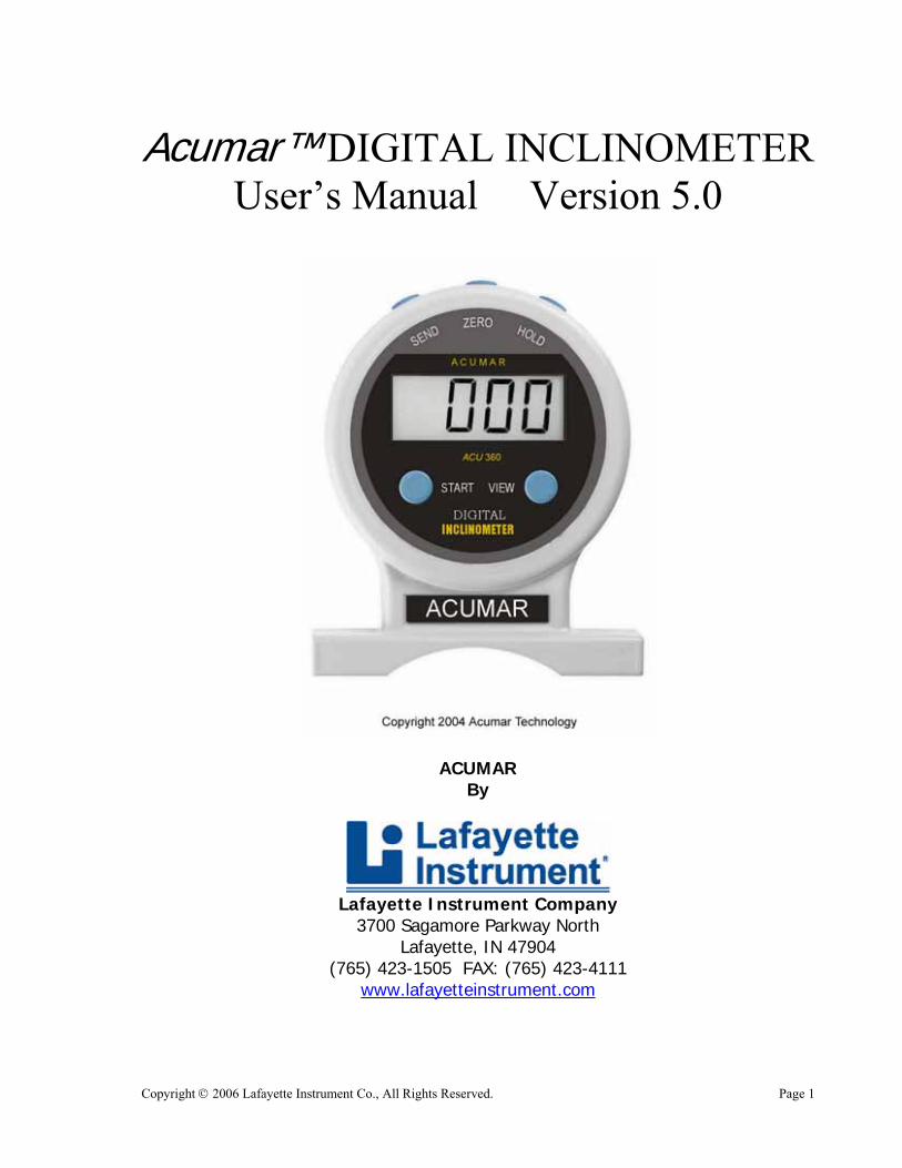
Acumar™ DIGITAL INCLINOMETER User’s Manual Version 5.0
ACUMAR By
Lafayette Instrument Company
3700 Sagamore Parkway North Lafayette, IN 47904
(765) 423-1505 FAX: (765) 423-4111 www.lafayetteinstrument.com

Copyright © 2006 Lafayette Instrument Co., All Rights Reserved. Page 2
Copyright © 2006 Lafayette Instrument Co., All Rights Reserved. Page 3
Introduction Inclinometers are instruments used to measure the angle of a subject with respect to a level or gravity. In medical or clinical applications, the inclinometer determines a person's range of motion. Typically, range of motion is referenced from the body's natural position. The flexion angle or extension angle of the body segment or joint under evaluation is then measured in degrees. Several different types of manual inclinometers exist on the market. The water-filled "Bubble" Inclinometer and the water-filled "Pendulum" Inclinometer are widely used. These inclinometers usually offer a two-degree marking for readings. Digital inclinometers typically display angle in one-degree increments for ease of reading. The Acumar Digital Inclinometer is the first digital inclinometer to provide easy-to-use, wireless data that can be logged into any PC. A built-in microprocessor automatically calculates and displays the actual range of motion of the joints. These special features of the Acumar Inclinometer assist evaluators to offer more objective range of motion measurements. The sole purpose of this User’s Manual is to describe the use of the Acumar Digital Inclinometer and/or its accessories and is not intended to describe medical procedures or standards. The user is advised to refer and follow specific procedures such as the AMA Guides* to the Evaluation of Permanent Impairment or any applicable state or local guidelines of procedures. Background The Acumar Digital Inclinometer was developed in response to many physicians and clinicians who expressed a need to have a modernized easy-to-use instrument to help document data in an objective manner. Acumar Technology recognizes and is grateful for the numerous physicians, clinicians and others who willingly participated in guiding the development. Acumar Technology is committed to continuing to serve the needs of the evaluation community and welcomes any input from the user in the field of evaluation and outcome assessment.
* AMA Guides to the Evaluation of Permanent Impairment 4th & 5th editions

Copyright © 2006 Lafayette Instrument Co., All Rights Reserved. Page 4
Copyright © 2006 Lafayette Instrument Co., All Rights Reserved. Page 5
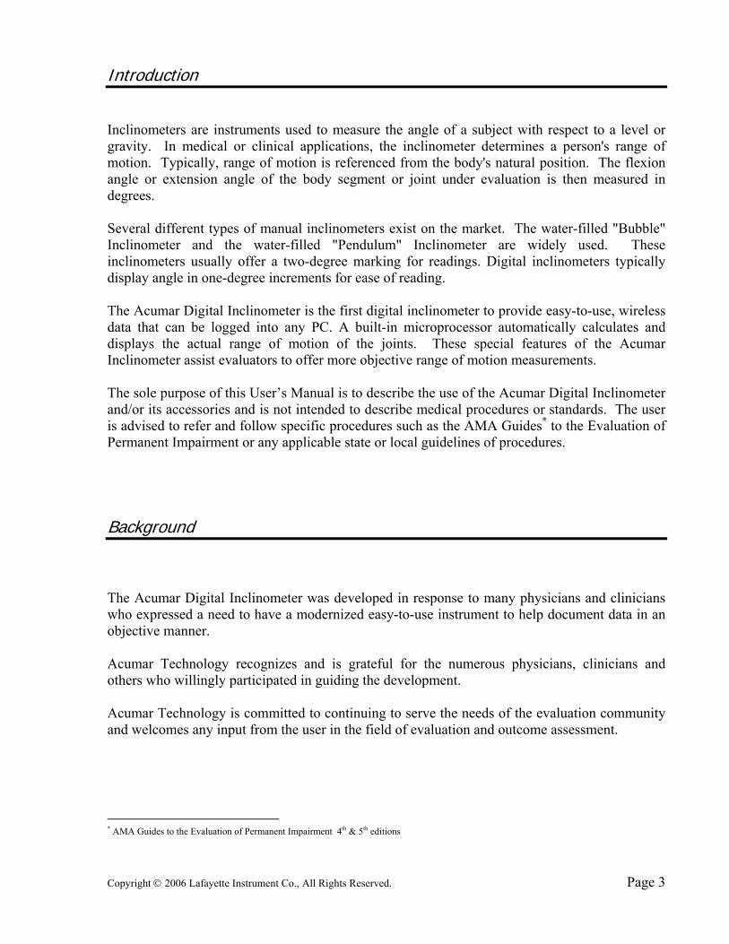
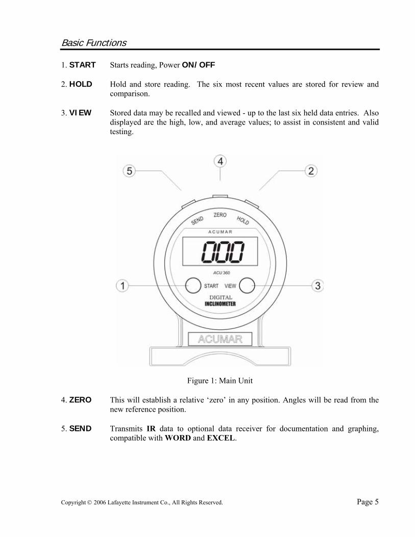
Basic Functions 1. START Starts reading, Power ON/OFF 2. HOLD Hold and store reading. The six most recent values are stored for review and
comparison. 3. VIEW Stored data may be recalled and viewed - up to the last six held data entries. Also
displayed are the high, low, and average values; to assist in consistent and valid testing.
Figure 1: Main Unit 4. ZERO This will establish a relative ‘zero’ in any position. Angles will be read from the
new reference position. 5. SEND Transmits IR data to optional data receiver for documentation and graphing,
compatible with WORD and EXCEL.
Copyright © 2006 Lafayette Instrument Co., All Rights Reserved. Page 6
Easy to Use, 1-2-3 Steps: Basic Operation
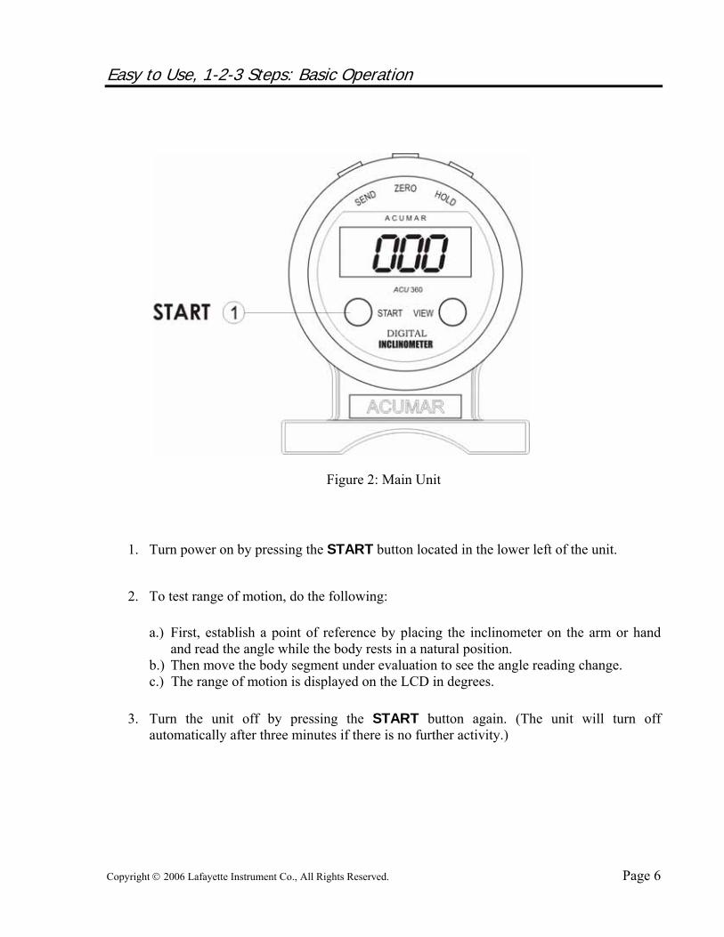
Figure 2: Main Unit
1. Turn power on by pressing the START button located in the lower left of the unit.
2. To test range of motion, do the following:
a.) First, establish a point of reference by placing the inclinometer on the arm or hand and read the angle while the body rests in a natural position.
b.) Then move the body segment under evaluation to see the angle reading change. c.) The range of motion is displayed on the LCD in degrees.
3. Turn the unit off by pressing the START button again. (The unit will turn off
automatically after three minutes if there is no further activity.)
Copyright © 2006 Lafayette Instrument Co., All Rights Reserved. Page 7
Basic Operation continued: Storing multiple data readings
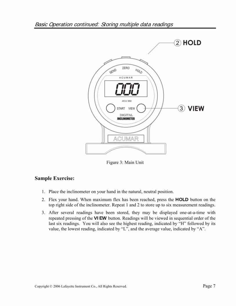
Figure 3: Main Unit
Sample Exercise:
1. Place the inclinometer on your hand in the natural, neutral position.
2. Flex your hand. When maximum flex has been reached, press the HOLD button on the top right side of the inclinometer. Repeat 1 and 2 to store up to six measurement readings.
3. After several readings have been stored, they may be displayed one-at-a-time with repeated pressing of the VIEW button. Readings will be viewed in sequential order of the last six readings. You will also see the highest reading, indicated by “H” followed by its value, the lowest reading, indicated by “L”, and the average value, indicated by “A”.

Copyright © 2006 Lafayette Instrument Co., All Rights Reserved. Page 8
Example: Cervical Lateral Bending using Single Inclinometry
Prepare the Inclinometer:
1. Press the START button on the Main Unit.
2. Ask individual to place head in neutral position.
3. Place the Main Unit over the calvarium.
Take Measurements:
1. Ask individual to bend their head to the left.
2. When individual reaches maximum range of motion, press the HOLD button to store the maximum left cervical lateral bending angle.
3. Ask individual to return to the neutral position.
4. Repeat measurement steps one through three 3 to 6 times to achieve validity criteria* of ±5O or 10%.
5. Follow steps one through four for right cervical lateral bending.
View Data:
1. To recall stored data, press the VIEW button to activate View Mode.
2. Pressing the VIEW button repeatedly will display the stored readings, as well as the “H” (high), “L” (low) and “A” (average) values.
* Refer to AMA Guides to the Evaluation of Permanent Impairment

Copyright © 2006 Lafayette Instrument Co., All Rights Reserved. Page 9
Advanced Application Techniques Extended: Functions for Advanced Users
1. VIEW (momentary press): • Subsequent presses display previously stored data, up to last six stored values.
Also the high and low absolute stored angles are displayed, followed by the average angular value.
2. ZERO (momentary press): • Will mark the new reference point as “zero.” • All subsequent readings are referenced to the marked zero point until the START
button is pressed to clear the memory setting.
When ZERO is pressed and held for three seconds: • The “zero” reference is set to the nearest 90º axis - for plumb measurements.
3. HOLD (momentary press): • Stores the current reading. • Up to six data readings. If you press more than six times, only the last six readings
will be stored. • AMA Guides suggest a minimum of three data and maximum of 6 data readings.
4. SEND (momentary press): • Sends stored data. • If no data has been stored, it will tab to the next data field.
Copyright © 2006 Lafayette Instrument Co., All Rights Reserved. Page 10
Questions and Answers for Advanced Users Q. How long can readings be stored? A. Indefinitely, until the START button is pressed. The unit will automatically shut off
power after 3 minutes of inactivity. However, the last set of data will still be in memory. Data remains even if the LCD display is off and the internal computer is in sleep mode. To wake up the memory and resume all functions, simply press VIEW. If you want to start a new series of measurements, press START. This will clear all data and settings so that the inclinometer is ready for a new set of tests.
Q. Can you set zero at any angle as a new zero reference? A. Yes. By pressing the ZERO button at any angle, the inclinometer will establish a new
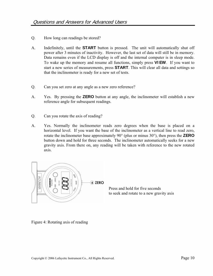
reference angle for subsequent readings. Q. Can you rotate the axis of reading? A. Yes. Normally the inclinometer reads zero degrees when the base is placed on a
horizontal level. If you want the base of the inclinometer as a vertical line to read zero, rotate the inclinometer base approximately 90° (plus or minus 30°), then press the ZERO button down and hold for three seconds. The inclinometer automatically seeks for a new gravity axis. From there on, any reading will be taken with reference to the new rotated axis.
Press and hold for five seconds to seek and rotate to a new gravity axis
Figure 4: Rotating axis of reading
Copyright © 2006 Lafayette Instrument Co., All Rights Reserved. Page 11
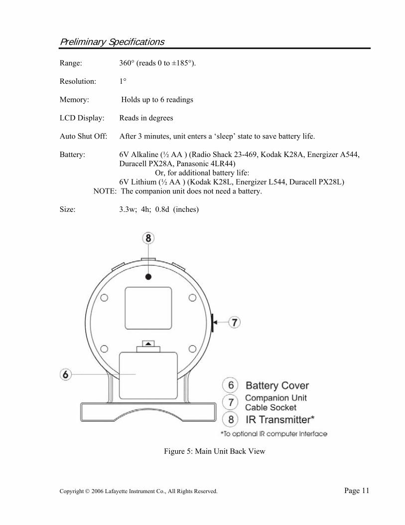
Preliminary Specifications Range: 360° (reads 0 to ±185°). Resolution: 1° Memory: Holds up to 6 readings LCD Display: Reads in degrees Auto Shut Off: After 3 minutes, unit enters a ‘sleep’ state to save battery life. Battery: 6V Alkaline (½ AA ) (Radio Shack 23-469, Kodak K28A, Energizer A544,
Duracell PX28A, Panasonic 4LR44) Or, for additional battery life: 6V Lithium (½ AA ) (Kodak K28L, Energizer L544, Duracell PX28L) NOTE: The companion unit does not need a battery. Size: 3.3w; 4h; 0.8d (inches)
Figure 5: Main Unit Back View

Copyright © 2006 Lafayette Instrument Co., All Rights Reserved. Page 12
Copyright © 2006 Lafayette Instrument Co., All Rights Reserved. Page 13
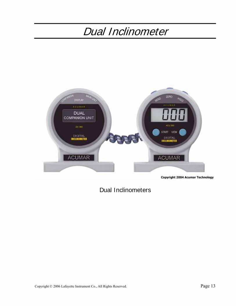
Dual Inclinometer
Dual Inclinometers
Copyright © 2006 Lafayette Instrument Co., All Rights Reserved. Page 14
Dual Inclinometer Basic Operations
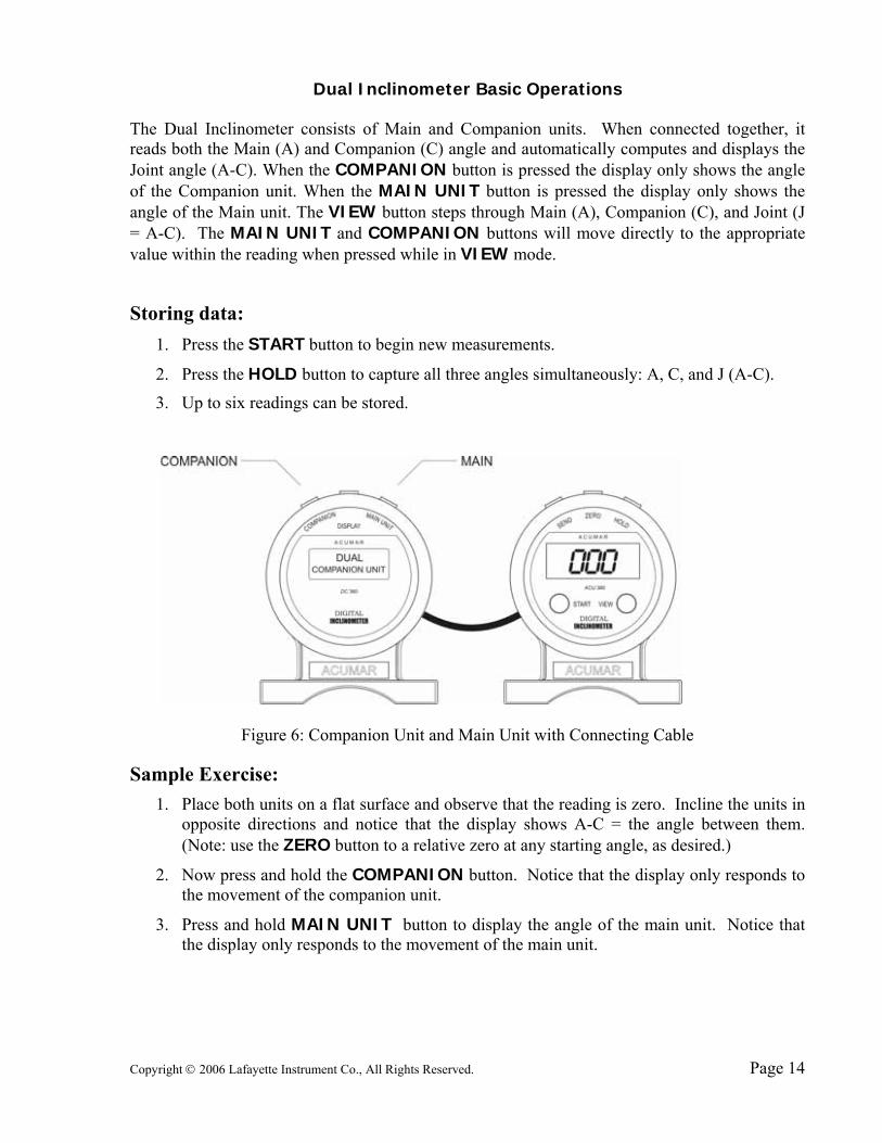
The Dual Inclinometer consists of Main and Companion units. When connected together, it reads both the Main (A) and Companion (C) angle and automatically computes and displays the Joint angle (A-C). When the COMPANION button is pressed the display only shows the angle of the Companion unit. When the MAIN UNIT button is pressed the display only shows the angle of the Main unit. The VIEW button steps through Main (A), Companion (C), and Joint (J = A-C). The MAIN UNIT and COMPANION buttons will move directly to the appropriate value within the reading when pressed while in VIEW mode.
Storing data: 1. Press the START button to begin new measurements.
2. Press the HOLD button to capture all three angles simultaneously: A, C, and J (A-C).
3. Up to six readings can be stored.
Figure 6: Companion Unit and Main Unit with Connecting Cable
Sample Exercise: 1. Place both units on a flat surface and observe that the reading is zero. Incline the units in
opposite directions and notice that the display shows A-C = the angle between them. (Note: use the ZERO button to a relative zero at any starting angle, as desired.)
2. Now press and hold the COMPANION button. Notice that the display only responds to the movement of the companion unit.
3. Press and hold MAIN UNIT button to display the angle of the main unit. Notice that the display only responds to the movement of the main unit.
Copyright © 2006 Lafayette Instrument Co., All Rights Reserved. Page 15
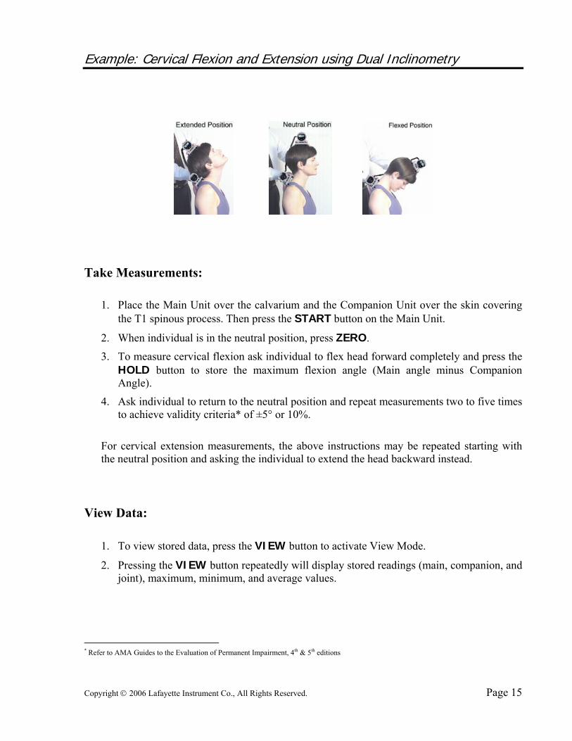
Example: Cervical Flexion and Extension using Dual Inclinometry
Take Measurements:
1. Place the Main Unit over the calvarium and the Companion Unit over the skin covering the T1 spinous process. Then press the START button on the Main Unit.
2. When individual is in the neutral position, press ZERO.
3. To measure cervical flexion ask individual to flex head forward completely and press the HOLD button to store the maximum flexion angle (Main angle minus Companion Angle).
4. Ask individual to return to the neutral position and repeat measurements two to five times to achieve validity criteria* of ±5° or 10%.
For cervical extension measurements, the above instructions may be repeated starting with the neutral position and asking the individual to extend the head backward instead.
View Data:
1. To view stored data, press the VIEW button to activate View Mode.
2. Pressing the VIEW button repeatedly will display stored readings (main, companion, and joint), maximum, minimum, and average values.
* Refer to AMA Guides to the Evaluation of Permanent Impairment, 4th & 5th editions

Copyright © 2006 Lafayette Instrument Co., All Rights Reserved. Page 16
Disclaimer
This manual is designed solely to illustrate the use of the Acumar Digital Inclinometer and/or its accessories, and is not intended nor implied to describe medical examination procedures. Selecting methods of examination and interpreting measured results are the responsibility of practitioners. Acumar will not warrant that any procedures described herein meet any current or past medical examination guides or procedures required by state or any local governments or other organizations. Acumar expressly disclaims all liability arising from use of this manual. Acumar Digital Inclinometer or related product(s) as stated in the warranty in the latter part of this user’s manual. The use of Acumar Digital Inclinometers to take objective measurements combined with Acumar™ excel templates or any other forms can produce patient files. Like any other patient data, if protection of the privacy of patient files is required, it is the sole responsibility of the provider and of the practitioner. Acumar disclaims all liability for any and all claims. Acumar™ does not express or imply that the any reference values that may appear on any forms are accurate, relevant, or clinically significant and hereby disclaims all liability for their clinical use herein. Medical judgment should be the ultimate faculty of the practitioner.
Copyright © 2006 Lafayette Instrument Co., All Rights Reserved. Page 17
One Year Limited Warranty Digital Inclinometer, Accessories “product(s)” If, within one year from the date of original purchase, the Acumar Technology’s Digital Inclinometer fails to function because of defects in materials or workmanship, the manufacturer will, at its option, either repair or replace such product(s). To be eligible for warranty service on your product(s), the registration card must be returned within 60 days of initial purchase. To obtain warranty service, contact your dealer for return address. Deliver the product (postpaid) to the location specified by your dealer. Purchaser must include the dated sales receipt (as proof of purchase), and a brief explanation describing why the product is inoperable or how it was damaged. This warranty does not cover damage resulting from accident, misuse or abuse, water, extreme temperatures, tampering, attachment of unauthorized accessories, servicing performed or attempted by unauthorized agencies, product(s) that have been modified in any fashion, product(s) that have not been maintained in accordance with the instructions in the manual, or any other conditions whatsoever that are beyond the control of the manufacturer. This product(s) are intended to be used by professional practitioners who are knowledgeable in examination procedures and applicability of test method and proper use. The manufacturer is not responsible for the interpretation of results and use of the information gathered by this product(s). Interpretation of the results are the sole responsibility of the user. In no event will the manufacturer be liable for damages, incidental or consequential, domestic or international, rising from the purchase and use or inability to use the product(s) even if the manufacturer has been advised of the possibility of such damages. Except as provided herein, the manufacturer makes no warranties, express or implied, including without limitation the implied warranties without limitation of merchantability and fitness for a particular purpose, loss of business, business interruption, loss of business information or other indirect or consequential loss arising out of the use or inability to use or supply or non-supply of the product(s). All warranties for the product(s), expressed or implied, are limited to the warranty period set forth above. If the product(s) do not perform as warranted herein, the original purchaser’s sole remedy will be the repair or replacement of the product(s) as provided above. This warranty gives you specific legal rights. You may also have other rights, which vary from state to state. Because of individual state regulations, some of the above limitations and exclusions may not apply to you.

Copyright © 2006 Lafayette Instrument Co., All Rights Reserved. Page 18
Copyright © 2006 Lafayette Instrument Co., All Rights Reserved. Page 19
Appendix A Acumar Ruler Attachment
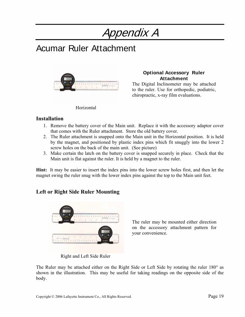
Optional Accessory Ruler
Attachment The Digital Inclinometer may be attached to the ruler. Use for orthopedic, podiatric, chiropractic, x-ray film evaluations.
Horizontal
Installation 1. Remove the battery cover of the Main unit. Replace it with the accessory adaptor cover
that comes with the Ruler attachment. Store the old battery cover. 2. The Ruler attachment is snapped onto the Main unit in the Horizontal position. It is held
by the magnet, and positioned by plastic index pins which fit snuggly into the lower 2 screw holes on the back of the main unit. (See picture)
3. Make certain the latch on the battery cover is snapped securely in place. Check that the Main unit is flat against the ruler. It is held by a magnet to the ruler.
Hint: It may be easier to insert the index pins into the lower screw holes first, and then let the magnet swing the ruler snug with the lower index pins against the top to the Main unit feet.
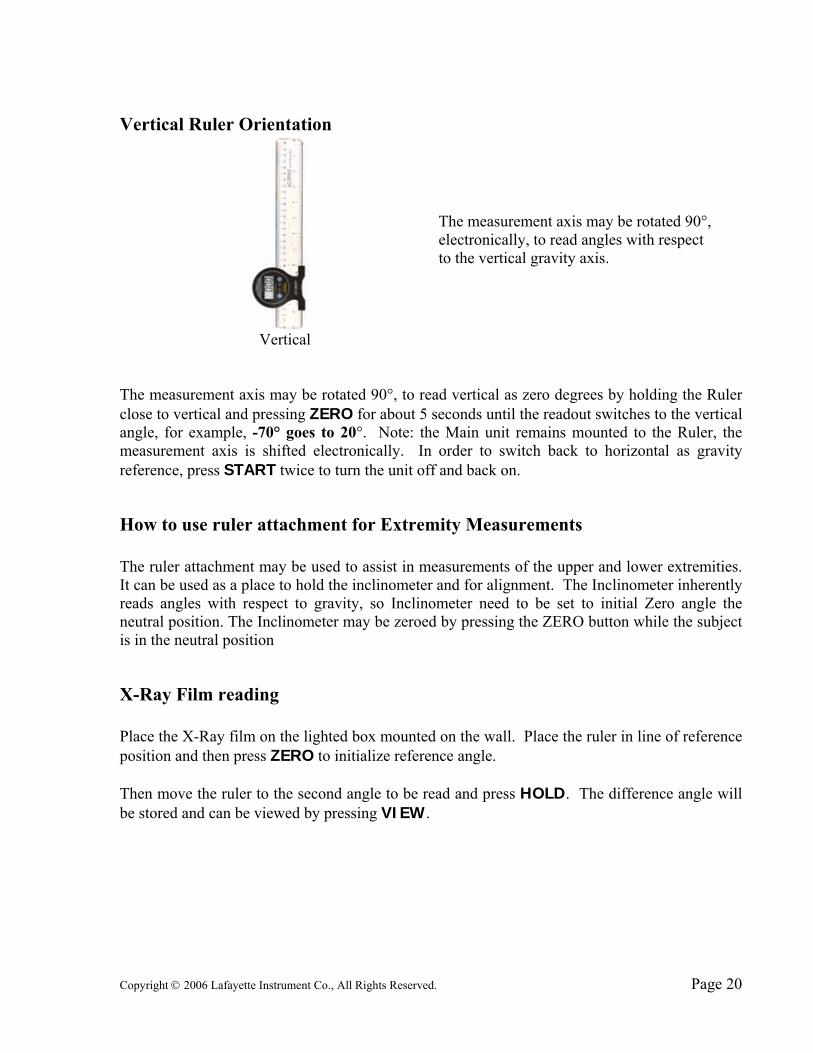
Left or Right Side Ruler Mounting
The ruler may be mounted either direction on the accessory attachment pattern for your convenience.
Right and Left Side Ruler The Ruler may be attached either on the Right Side or Left Side by rotating the ruler 180° as shown in the illustration. This may be useful for taking readings on the opposite side of the body.
Copyright © 2006 Lafayette Instrument Co., All Rights Reserved. Page 20
Vertical Ruler Orientation
The measurement axis may be rotated 90°, electronically, to read angles with respect to the vertical gravity axis.
Vertical The measurement axis may be rotated 90°, to read vertical as zero degrees by holding the Ruler close to vertical and pressing ZERO for about 5 seconds until the readout switches to the vertical angle, for example, -70° goes to 20°. Note: the Main unit remains mounted to the Ruler, the measurement axis is shifted electronically. In order to switch back to horizontal as gravity reference, press START twice to turn the unit off and back on.
How to use ruler attachment for Extremity Measurements The ruler attachment may be used to assist in measurements of the upper and lower extremities. It can be used as a place to hold the inclinometer and for alignment. The Inclinometer inherently reads angles with respect to gravity, so Inclinometer need to be set to initial Zero angle the neutral position. The Inclinometer may be zeroed by pressing the ZERO button while the subject is in the neutral position
X-Ray Film reading Place the X-Ray film on the lighted box mounted on the wall. Place the ruler in line of reference position and then press ZERO to initialize reference angle. Then move the ruler to the second angle to be read and press HOLD. The difference angle will be stored and can be viewed by pressing VIEW.

Copyright © 2006 Lafayette Instrument Co., All Rights Reserved. Page 21
X Ray Film Reading
Place the X Ray film on the wall mounted light box. Place the ruler in line of reference position and then press ZERO to initialize reference angle to zero. Then move the ruler to the second angle to be read and press HOLD. The difference angle will be stored and can be viewed by pressing VIEW. Disclaimers: This example is not medical advice, but only for illustrating the intended use of the ruler.
Male Kyphosis Versus Age
Age 10+ 20+ 30+ 40+ 50+ 60+ Max 42 47 49 50 51 52 Min 8 11 13 17 22 25
Norm 25 26 29 31 33 35
Female Kyphosis Angle Versus Age
Age 10+ 20+ 30+ 40+ 50+ 60+ Max 41 40 42 50 53 54 Min 10 12 15 18 22 34
Norm 26 27 28 33 41 45
Kyphosis angle versus Age
42
4749 50 51 52
811
13
17
222525 26
2931
3335
0
10
20
30
40
50
60
10+ 20+ 30+ 40+ 50+ 60+
Male Age
Deg
rees
max
norm
min
Kyphosis angle versus Age
41 4042
5053 54
1012
1518
22
34
26 27 28
33
41
45
0
10
20
30
40
50
60
10+ 20+ 30+ 40+ 50+ 60+
Female Age
Deg
rees
max
norm
min
Copyright © 2006 Lafayette Instrument Co., All Rights Reserved. Page 22
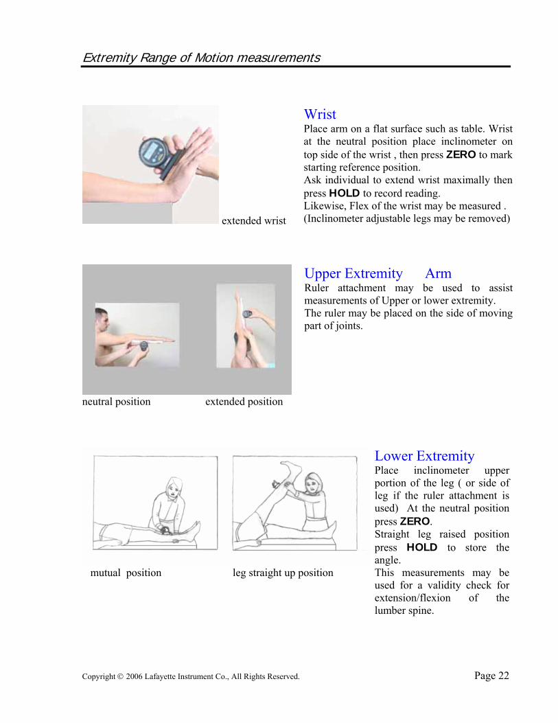
Extremity Range of Motion measurements
extended wrist
Wrist Place arm on a flat surface such as table. Wrist at the neutral position place inclinometer on top side of the wrist , then press ZERO to mark starting reference position. Ask individual to extend wrist maximally then press HOLD to record reading. Likewise, Flex of the wrist may be measured . (Inclinometer adjustable legs may be removed)
neutral position extended position
Upper Extremity Arm Ruler attachment may be used to assist measurements of Upper or lower extremity. The ruler may be placed on the side of moving part of joints.
mutual position leg straight up position
Lower Extremity Place inclinometer upper portion of the leg ( or side of leg if the ruler attachment is used) At the neutral position press ZERO. Straight leg raised position press HOLD to store the angle. This measurements may be used for a validity check for extension/flexion of the lumber spine.
Copyright © 2006 Lafayette Instrument Co., All Rights Reserved. Page 23
Appendix B
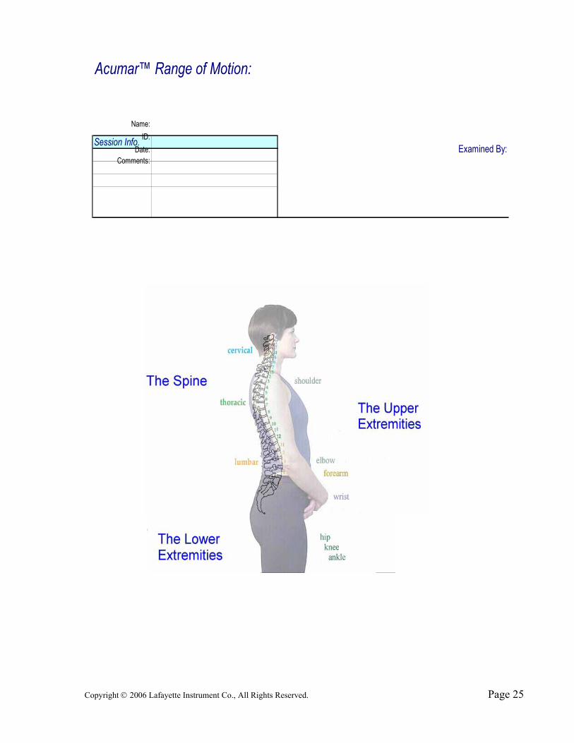
Acumar Sample Data Recording Forms The following seven pages of forms are included for your convenience. They cover spinal, upper extremity, and lower extremity range of motion measurements. These forms may be copied for the purpose of taking measurements using Acumar Technology Digital Inclinometers, all other rights are reserved.

Copyright © 2006 Lafayette Instrument Co., All Rights Reserved. Page 24
Copyright © 2006 Lafayette Instrument Co., All Rights Reserved. Page 25
Session Info.0
Saturday, January 00, 19000
3 TRUE
Comments:
Acumar™ Range of Motion:
Name:ID:
Date: Examined By:

Copyright © 2006 Lafayette Instrument Co., All Rights Reserved. Page 26
0
Saturday, January 00, 19000
2 FALSE FALSE 2
Section Description Test Max. Ave. Var.Calvarium flexion angleT1 angleCervical flexion ROM
Calvarium extension angleT1 angleCervical extension ROM
Flex. / exten. ankylosis (SINGLE)
Calvarium left lateral flexion angleT1 angleCervical left lateral flexion ROM
Calvarium right lateral flexion angleT1 angleCervical right lateral flexion ROM
Lateral flexion ankylosis (SINGLE)
Cervical left rotation ROM (SINGLE)
Cervical right rotation ROM (SINGLE)
Rotation ankylosis (SINGLE)
6 Cervical Lateral Ankylosis
2 Cervical Extension
Cervical Left Lateral Bending
Cervical Right Lateral Bending
3 Cervical Sagittal Ankylosis
5
ID:
Acumar™ Range of Motion:The Spine
Name:Session Info.
Date:
1 Cervical Flexion
Comments:
Cervical Range of Motion
4
8 Cervical Right Rotation
9 Cervical Rotational Ankylosis
7 Cervical Left Rotation
Examined By:

Copyright © 2006 Lafayette Instrument Co., All Rights Reserved. Page 27
Section Description Test Max. Ave. Var.T1 angleT12 angleKyphosis in Thoracic extension
T1 flexion angleT12 angleThoracic flexion ROM
T1 left rotation angleT12 angleThoracic left rotation ROM
T1 right rotation angleT12 angleThoracic right rotation ROM
Rotation ankylosis (SINGLE)
Section Description Test Max. Ave. Var.T12 flexion angleSacral angleLumbar flexion ROM
T12 extension angleSacral angleLumbar extension ROM
Left SLR angle (SINGLE)
Right SLR angle (SINGLE)
T12 left lateral flexion angleSacral angleLumbar left lateral flexion ROM
T12 right lateral flexion angleSacral angleLumbar right lateral flexion ROM
Lumbar lateral ankylosis (SINGLE)
Lumbar Ankylosis
7
Lumbar Right Straight Leg Raising
4
Lumbar Right Lateral Bending
6
Lumbar Left Lateral Bending
5
3 Lumbar Left Straight Leg Raising
1
Thoracic Rotation Ankylosis
2
Thoracic Right Rotation
Lumbar Extension
Thoracic Range of Motion
2 Thoracic Flexion
Lumbar Range of Motion
Lumbar Flexion
5
1 Thoracic Extension Ankylosis
Thoracic Left Rotation
3
4
Copyright © 2006 Lafayette Instrument Co., All Rights Reserved. Page 28
0
Saturday, January 00, 19000
16 FALSE Test Test 0 1#
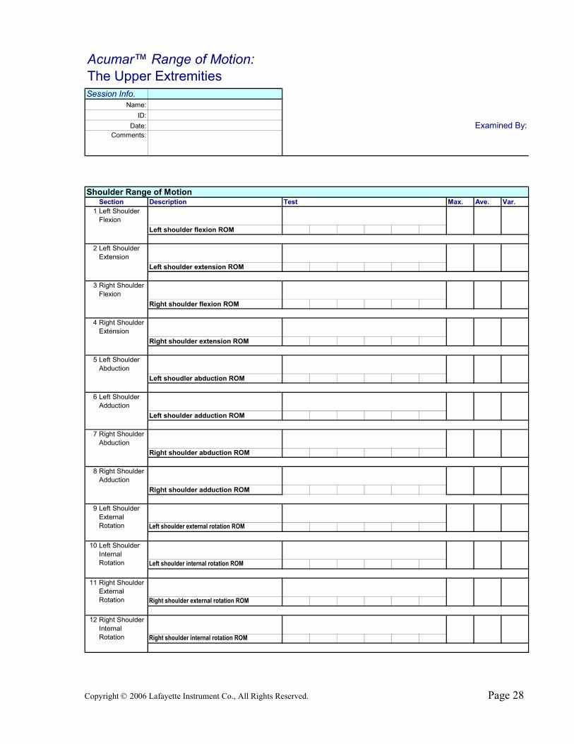
Section Description Test Max. Ave. Var.Left upper arm angleLeft shoulder angleLeft shoulder flexion ROM
Left upper arm angleLeft shoulder angleLeft shoulder extension ROM
Right upper arm angleRight shoulder angleRight shoulder flexion ROM
Right upper arm angleRight shoulder angleRight shoulder extension ROM
Left upper arm angleLeft shoulder angleLeft shoudler abduction ROM
Left upper arm angleLeft shoulder angleLeft shoulder adduction ROM
Right upper arm angleRight shoulder angleRight shoulder abduction ROM
Right upper arm angleRight shoulder angleRight shoulder adduction ROM
Left upper arm angleLeft shoulder angleLeft shoulder external rotation ROM
Left upper arm angleLeft shoulder angleLeft shoulder internal rotation ROM
Right upper arm angleRight shoulder angleRight shoulder external rotation ROM
Right upper arm angleRight shoulder angleRight shoulder internal rotation ROM
Right Shoulder Internal Rotation
12
8
3
4
5
Right Shoulder Abduction
7
9 Left Shoulder External Rotation
Left Shoulder Internal Rotation
Name:Session Info.
Acumar™ Range of Motion:The Upper Extremities
1 Left Shoulder Flexion
Date:ID:
Shoulder Range of Motion
Comments:
Right Shoulder Adduction
Left Shoulder Abduction
6 Left Shoulder Adduction
Right Shoulder External Rotation
11
10
Right Shoulder Flexion
Right Shoulder Extension
2 Left Shoulder Extension
Examined By:
Copyright © 2006 Lafayette Instrument Co., All Rights Reserved. Page 29
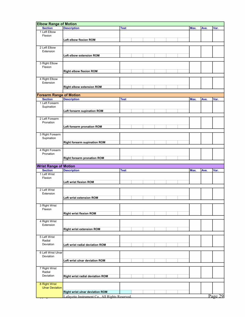
Section Description Test Max. Ave. Var.Left forearm angleLeft upper arm angleLeft elbow flexion ROM
Left forearm angleLeft upper arm angleLeft elbow extension ROM
Right forearm angleRight upper arm angleRight elbow flexion ROM
Right forearm angleRight upper arm angleRight elbow extension ROM
Section Description Test Max. Ave. Var.Left hand angleLeft forearm angleLeft forearm supination ROM
Left hand angleLeft forearm angleLeft forearm pronation ROM
Right hand angleRight forearm angleRight forearm supination ROM
Right hand angleRight forearm angleRight forearm pronation ROM
Section Description Test Max. Ave. Var.Left wrist angleLeft forearm angleLeft wrist flexion ROM
Left wrist angleLeft forearm angleLeft wrist extension ROM
Right wrist angleRight forearm angleRight wrist flexion ROM
Right wrist angleRight forearm angleRight wrist extension ROM
Left wrist angleLeft forearm angleLeft wrist radial deviation ROM
Left wrist angleLeft forearm angleLeft wrist ulnar deviation ROM
Right wrist angleRight forearm angleRight wrist radial deviation ROM
Right wrist angleRight forearm angleRight wrist ulnar deviation ROM
4 Right Forearm Pronation
2 Left Wrist Extension
3
Left Forearm Supination
1
Wrist Range of Motion
Left Wrist Flexion
1
Left Elbow Flexion
Left Wrist Ulnar Deviation
Forearm Range of Motion
Elbow Range of Motion
1
7
6
Right Forearm Supination
8
Right Wrist Extension
4
Right Wrist Flexion
3
5 Left Wrist Radial Deviation
Right Wrist Ulnar Deviation
Right Wrist Radial Deviation
2 Left Forearm Pronation
4 Right Elbow Extension
Left Elbow Extension
2
3 Right Elbow Flexion
Copyright © 2006 Lafayette Instrument Co., All Rights Reserved. Page 30
0
Saturday, January 00, 19000
2 FALSE Test Test 0 1
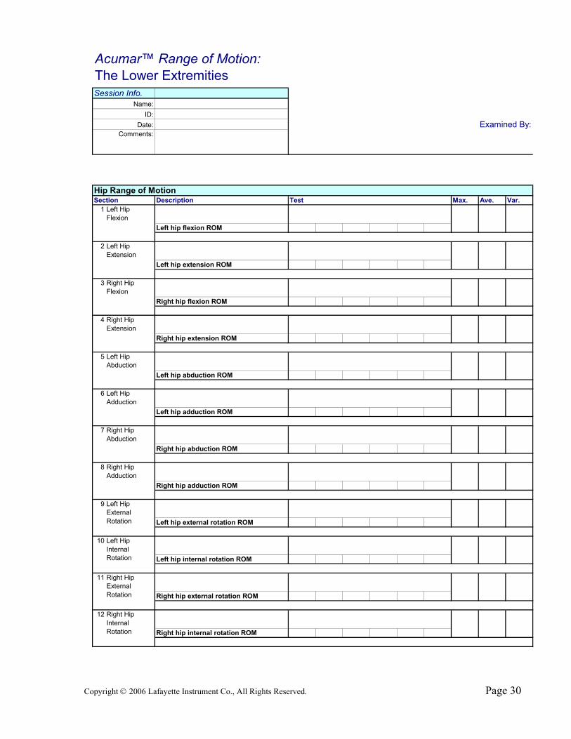
Section Description Test Max. Ave. Var.Left upper leg angleLeft hip angleLeft hip flexion ROM
Left upper leg angleLeft hip angleLeft hip extension ROM
Right upper leg angleRight hip angleRight hip flexion ROM
Right upper leg angleRight hip angleRight hip extension ROM
Left upper leg angleLeft hip angleLeft hip abduction ROM
Left upper leg angleLeft hip angleLeft hip adduction ROM
Right upper leg anleRight hip angleRight hip abduction ROM
Right upper leg anleRight hip angleRight hip adduction ROM
Left upper leg angleLeft hip angleLeft hip external rotation ROM
Left upper leg angleLeft hip angleLeft hip internal rotation ROM
Right upper leg angleRight hip angleRight hip external rotation ROM
Right upper leg angleRight hip angleRight hip internal rotation ROM
Comments:
Hip Range of Motion
1 Left Hip Flexion
2 Left Hip Extension
Right Hip Flexion
6
7
8 Right Hip Adduction
Left Hip Adduction
Right Hip Abduction
3
4 Right Hip Extension
5 Left Hip Abduction
Name:ID:
Date:
Acumar™ Range of Motion:The Lower Extremities
Left Hip External Rotation
9
10 Left Hip Internal Rotation
Right Hip External Rotation
11
12 Right Hip Internal Rotation
Session Info.
Examined By:
Copyright © 2006 Lafayette Instrument Co., All Rights Reserved. Page 31
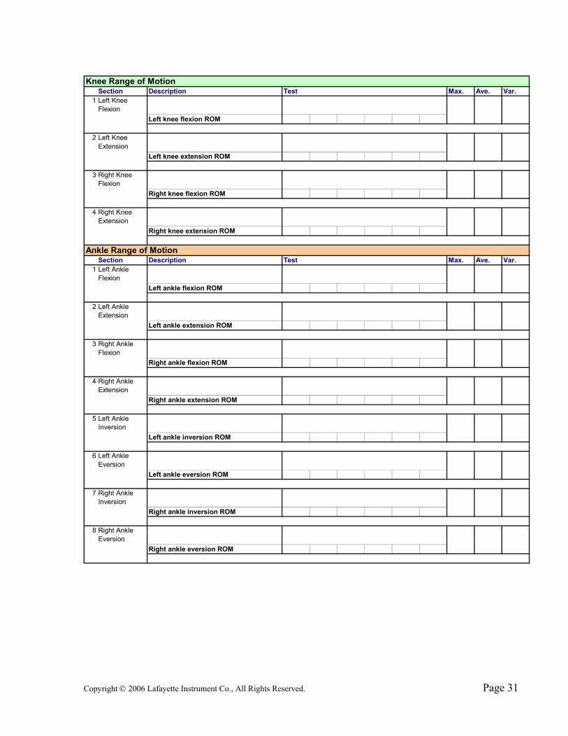
Section Description Test Max. Ave. Var.Left upper leg angleLeft fore leg angleLeft knee flexion ROM
Left upper leg angleLeft fore leg angleLeft knee extension ROM
Right upper leg angleRight fore leg angleRight knee flexion ROM
Right upper leg angleRight fore leg angleRight knee extension ROM
Section Description Test Max. Ave. Var.Left fore leg angleLeft ankle angleLeft ankle flexion ROM
Left fore leg angleLeft ankle angleLeft ankle extension ROM
Right fore leg angleRight ankle angleRight ankle flexion ROM
Right fore leg angleRight ankle angleRight ankle extension ROM
Left fore leg angleLeft ankle angleLeft ankle inversion ROM
Left fore leg angleLeft ankle angleLeft ankle eversion ROM
Right fore leg angleRight ankle angleRight ankle inversion ROM
Right fore leg angleRight ankle angleRight ankle eversion ROM
Knee Range of Motion
Ankle Range of Motion
1 Left Ankle Flexion
1 Left Knee Flexion
Left Knee Extension
2
3 Right Knee Flexion
Right Knee Extension
4
Right Ankle Eversion
Left Ankle Extension
8
7 Right Ankle Inversion
5 Left Ankle Inversion
Left Ankle Eversion
6
2
Right Ankle Extension
4
3 Right Ankle Flexion

Copyright © 2006 Lafayette Instrument Co., All Rights Reserved. Page 32
ACUMAR By
Lafayette Instrument Company
3700 Sagamore Parkway North Lafayette, IN 47904
Tel: (765) 423-1505 FAX: (765) 423-4111 www.lafayetteinstrument.com
Copyright © 2006 Lafayette Instrument Co., All Rights Reserved.