Embed Size (px)
Citation preview
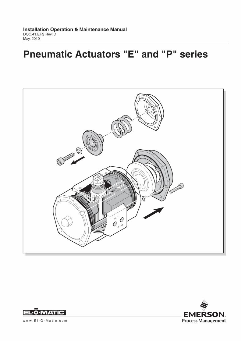
Pneumatic Actuators "E" and "P" series
Installation Operation & Maintenance ManualDOC.41.EFS Rev: DMay, 2010
w w w . E l - O - M a t i c . c o m
TM
schaal 1:1
������
��������������� �������������������������DOC.41.EFS Rev: D
�������
TM
CONTENTS
1 INTRODUCTION ...................................................................................................................... 41.1 Identification ..................................................................................................................................41.2 Product code .................................................................................................................................6
2 CONSTRUCTION DETAILS .................................................................................................... 93 PRINCIPLES OF OPERATION .............................................................................................. 10
3.1 Air connections double acting ....................................................................................................103.2 Air connections spring return .....................................................................................................113.3 Recommended tubing sizes ........................................................................................................123.4 Air consumption litre/stroke at atmospheric pressure ................................................................12
4 ASSEMBLY CODES .............................................................................................................. 134.1 Installation ...................................................................................................................................144.2 Stroke adjustment .......................................................................................................................16
4.2.1 L1 one way stroke adjustment ..........................................................................................174.2.2 DSA two way stroke adjustment .......................................................................................19
4.3 Tool table .....................................................................................................................................23
5 DISASSEMBLY ...................................................................................................................... 245.1 Before starting .............................................................................................................................245.2 Removing endcaps type ES/ED 25 to 350 ..................................................................................255.3 Removing endcaps Type PE ......................................................................................................265.4 Removing Pistons .......................................................................................................................275.5 Removing insert ..........................................................................................................................28
6 REASSEMBLY ....................................................................................................................... 296.1 Reassembly guide band and shaft .............................................................................................296.2 Reassembly pistons ....................................................................................................................306.3 Reassembly endcaps double acting actuators ............................................................................316.4 Reassembly endcaps single acting actuators ES25 - ES350 ....................................................326.5 Reassembly endcaps single acting actuators ES600 - PS4000 .................................................336.6 Reassembly of springclip and insert ..........................................................................................35
7 PARTS LIST .......................................................................................................................... 36
TABLE DES MATIERES
1 INTRODUCTION ...................................................................................................................... 41.1 Identification ..................................................................................................................................41.2 Code de produit .............................................................................................................................7
2 DETAILS DE LA CONSTRUCTION ........................................................................................ 93 COMMANDE ......................................................................................................................... 10
3.1 Raccords à air, modèle à double effet .........................................................................................103.2 Raccords à air, modèle à rappel par ressort ...............................................................................113.3 Dimensions recommandées pour la tuyauterie ..........................................................................123.4 Consommation d'air litre/course à pression atmosphérique ......................................................12
4 CODES DE MONTAGE .......................................................................................................... 134.1 Installation ...................................................................................................................................144.2 Réglage de la course ..................................................................................................................16
4.2.1 Réglage de la limitation de course unilatérale L1 .............................................................174.2.2 Réglage de la limitation de course bilatérale DSA ...........................................................19
4.3 Tableau outillage ........................................................................................................................23
�����
��������������� �������������������������DOC.41.EFS Rev: D�������
TM
5 DEMONTAGE ....................................................................................................................... 245.1 Préparations ................................................................................................................................245.2 Démontage des couvercles type ES/ED 25 jusqu'à 350 .............................................................255.3 Démontage des couvercles, type PE ..........................................................................................265.4 Démontage des pistons/axe, série E et P ...................................................................................275.5 Démontage de l'insert ................................................................................................................28
6 REMONTAGE ........................................................................................................................ 296.1 Remontage de la bande guidage et de l'arbre ............................................................................296.2 Remontage des pistons ..............................................................................................................306.3 Remontage des couvercles des actionneurs à double effet ........................................................316.4 Remontage des couvercles des actionneurs à simple effet ES25 - ES350 ...............................326.5 Remontage des couvercles des actionneurs à simple effet ES600 - PS4000 ...........................336.6 Remontage du circlip et insertion ................................................................................................35
7 LISTA DE PIEZAS ................................................................................................................ 36
CONTENIDO
1 INTRODUCCIÓN .................................................................................................................... 41.1 Identificación .................................................................................................................................41.2 Código de producto .......................................................................................................................8
2 DETAILS DE LA CONSTRUCTION......................................................................................... 93 PRINCIPIOS DE FUNCIONAMIENTO ................................................................................... 10
3.1 Conexiones de aire - doble efecto ...............................................................................................103.2 Conexiones de aire - simple efecto .............................................................................................113.3 Diámetros de tubo recomendados ..............................................................................................123.4 Consumo de aire (litros/maniobra) a presión atmosférica ..........................................................12
4 CÓDIGOS DE MONTAJE ...................................................................................................... 134.1 Instalación ...................................................................................................................................144.2 Ajuste de carrera .........................................................................................................................16
4.2.1 Ajuste de carrera de un sentido L1 ...................................................................................174.2.2 Ajuste de carrera en dos sentidos DSA ...........................................................................19
4.2 Tabla de herramientas .................................................................................................................23
5 DESARME ............................................................................................................................. 245.1 Antes de empezar .......................................................................................................................245.2 Desmontaje de las tapas laterales tipo ES/ED 25 hasta 350 .....................................................255.3 Desmontaje de las tapas laterales Tipo PE ................................................................................265.4 Desmontaje de los Pistones/Eje, series P y E ............................................................................275.5 Extracción del elemento insertado ..............................................................................................28
6 REARME ................................................................................................................................ 296.1 Rearmar la banda guía y el eje ...................................................................................................296.2 Rearme de pistones ....................................................................................................................306.3 Rearme de tapas laterales de actuadores de doble efecto .........................................................316.4 Rearme de las tapas laterales de los actuadores de simple efecto ES25 - ES350 ....................326.5 Rearme de las tapas laterales de los actuadores de simple efecto ES600 - PS4000 ................336.6 Rearme del circlip y del elemento insertado ...............................................................................35
7 NOMENCLATURE DES PIECES .......................................................................................... 36
�
������
��������������� �������������������������DOC.41.EFS Rev: D
�������
TM
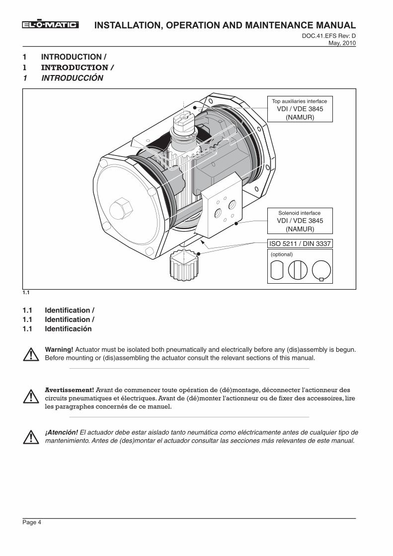
(NAMUR)VDI / VDE 3845
ISO 5211 / DIN 3337
(optional)
Solenoid interface
(NAMUR)VDI / VDE 3845
Top auxiliaries interface
schaal 1:1
1 INTRODUCTION / �� �������������1 INTRODUCCIÓN
1.1
1.1 Identification / 1.1 Identification / 1.1 Identificación
Warning! Actuator must be isolated both pneumatically and electrically before any (dis)assembly is begun. Before mounting or (dis)assembling the actuator consult the relevant sections of this manual.
�������������������������� ��������� �������������������������� ���������� ����� ��������������������� ���������������������� ���������� ��������� ��������� ����� ������ �� ������� �������������
¡Atención! El actuador debe estar aislado tanto neumática como eléctricamente antes de cualquier tipo de mantenimiento. Antes de (des)montar el actuador consultar las secciones más relevantes de este manual.
������
��������������� �������������������������DOC.41.EFS Rev: D�������
TM
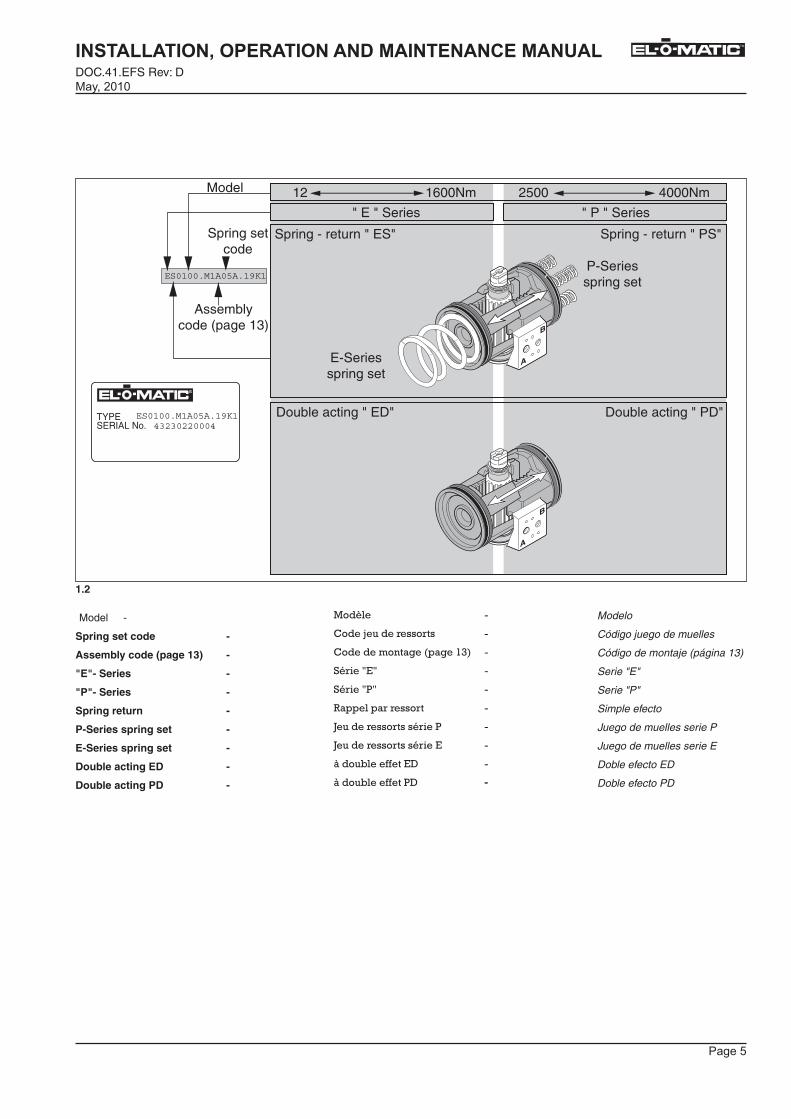
1.2
TYPESERIAL No.
ES0100.M1A05A.19K1
ES0100.M1A05A.19K1
43230220004
Assemblycode (page 13)
Spring setcode
E-Seriesspring set
P-Seriesspring set
" E " Series
12 1600Nm 2500 4000Nm
" P " Series
Model
Spring - return " ES" Spring - return " PS"
Double acting " ED" Double acting " PD"
Model -
Spring set code -
Assembly code (page 13) -
"E"- Series -
"P"- Series -
Spring return -
P-Series spring set -
E-Series spring set -
Double acting ED -
Double acting PD -
�������
!���"���� ��� ���
!�����������������#$��
%� ��&'&�
%� ��&(&�
)������� � ��� ��
*���� ��� ����� ��(�
*���� ��� ����� ��'�
+����,������'-�
+����,������(-� -
Modelo
Código juego de muelles
Código de montaje (página 13)
Serie "E"
Serie "P"
Simple efecto
Juego de muelles serie P
Juego de muelles serie E
Doble efecto ED
Doble efecto PD
������
��������������� �������������������������DOC.41.EFS Rev: D
�������
TM
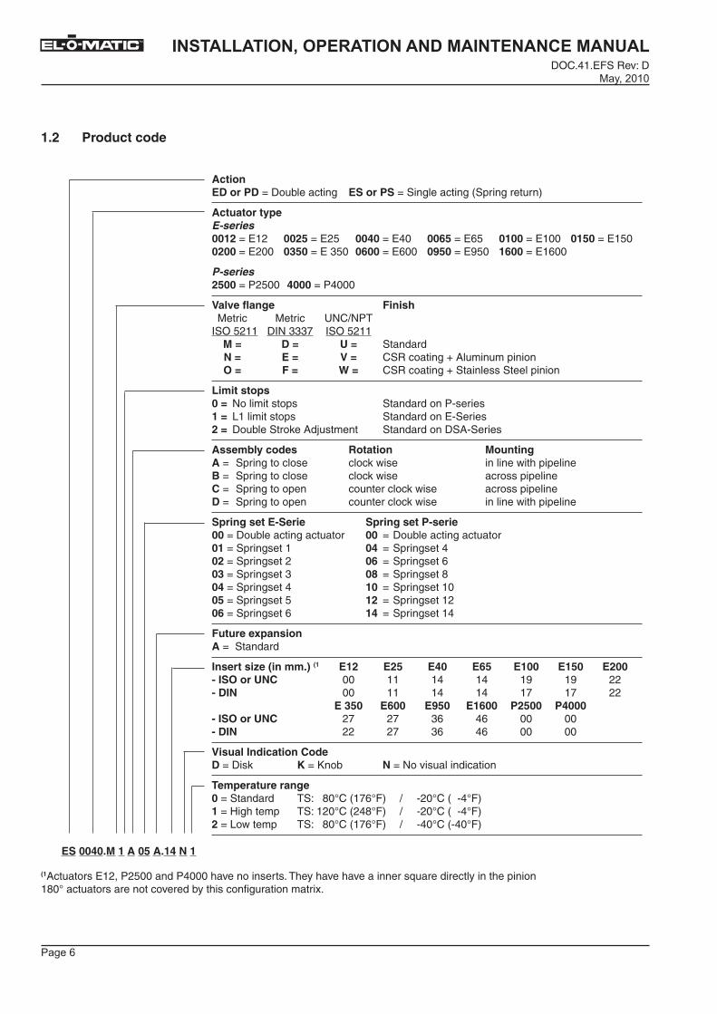
Action ED or PD = Double acting ES or PS = Single acting (Spring return)
Actuator typeE-series0012 = E12 0025 = E25 0040 = E40 0065 = E65 0100 = E100 0150 = E1500200 = E200 0350 = E 350 0600 = E600 0950 = E950 1600 = E1600
P-series2500 = P2500 4000 = P4000
Valve flange Finish Metric Metric UNC/NPT ISO 5211 DIN 3337 ISO 5211 M = D = U = Standard N = E = V = CSR coating + Aluminum pinion O = F = W = CSR coating + Stainless Steel pinion
Limit stops0 = No limit stops Standard on P-series1 = L1 limit stops Standard on E-Series2 = Double Stroke Adjustment Standard on DSA-Series
Assembly codes Rotation MountingA = Spring to close clock wise in line with pipelineB = Spring to close clock wise across pipelineC = Spring to open counter clock wise across pipelineD = Spring to open counter clock wise in line with pipeline
Spring set E-Serie Spring set P-serie00 = Double acting actuator 00 = Double acting actuator01 = Springset 1 04 = Springset 402 = Springset 2 06 = Springset 603 = Springset 3 08 = Springset 804 = Springset 4 10 = Springset 1005 = Springset 5 12 = Springset 1206 = Springset 6 14 = Springset 14
Future expansionA = Standard
Insert size (in mm.) (1 E12 E25 E40 E65 E100 E150 E200- ISO or UNC 00 11 14 14 19 19 22- DIN 00 11 14 14 17 17 22 E 350 E600 E950 E1600 P2500 P4000- ISO or UNC 27 27 36 46 00 00- DIN 22 27 36 46 00 00
Visual Indication CodeD = Disk K = Knob N = No visual indication
Temperature range0 = Standard TS: 80°C (176°F) / -20°C ( -4°F)1 = High temp TS: 120°C (248°F) / -20°C ( -4°F)2 = Low temp TS: 80°C (176°F) / -40°C (-40°F)
1.2 Product code
ES 0040.M 1 A 05 A.14 N 1
(1Actuators E12, P2500 and P4000 have no inserts. They have have a inner square directly in the pinion180° actuators are not covered by this configuration matrix.
������
��������������� �������������������������DOC.41.EFS Rev: D�������
TM
� � � � ��������������������.�-�����/� 0��� � ����� �.�'�����/� 0����1� 20�������
�����!��"#��������$$�%�.�'#3� $$%&�.�'34� $$'$�.�'56� $$(&�.�'74� $�$$�.�'#66� $�&$�.�'#46$%$$�.�'366� $)&$�.�'�$46� $($$�.�'766� $*&$�.�'846� �($$�.�'#766�
��������%&$$�.�(3466� '$$$�.�(5666
��+�����,-+����� �!��,-.����!��������������� ����� �� ����� 9:!;:(<�=%>�43##� -=:�$$$?� =%>�43##�� /�0� �0� �0� %����� �� ��0� ��0� 1�0� !%)�@���������A�����������B��� ��0� 2�0� ��0� !%)�@���������A�'��������B��
3�!!�����4���$�0�C���D�,,� �E���� %����� ��,��( � ����0� F#�D�,,� �E���� %����� ��,��' % ��%�0�-����� �D�,,� �E���� %����� ��,��-%� % ��
�,!+���5�� ������������ /���+�� �.� 1� ����G��� ���9� E�� ����� �� �����E� �F�����6�.� 1� ����G��� ���9� E�� ����� �� �E� �F�������.� 1� H������ �������9� E�� ����� �� �E� �F������.� 1� H������ �������9� E�� ����� �� �����E� �F�����
2�5���.�4���7 ����� 2�5���.�4����7�����$$�0�-�����/� 0�� ���� �,� $$� 0�-�����/� 0�� ���� �,$��0�1� ���E�#� $'� 0�1� ���E�5$%�0�1� ���E�3� $(� 0�1� ���E�7$)�0�1� ���E�$� $8� 0�1� ���E�I$'�0�1� ���E�5� �$� 0�1� ���E�#6$&�0�1� ���E�4� �%� 0�1� ���E�#3$(�0�1� ���E�7� �'� 0�1� ���E�#5
9��:�,�������;�������� �.��%����� ��
���������4��<�����=>�<�� ��%� �%&� �'$� �(&� ��$$� ��&$� �%$$7�� �������� 66� ##� #5� #5� #8� #8� 337���� 66� ##� #5� #5� #?� #?� 33� ��)&$� �($$� �*&$� ��($$� �%&$$� �'$$$7�� �������� 3?� 3?� $7� 57� 66� 667���� 33� 3?� $7� 57� 66� 66
����+�4�����.�%��,� ?�.�C����� ��.�C���%�����E��
���#��+���!������$�.�%����� ��<�� ��� � <%J���I6K!��#?7K1�� ;� 36K!���� 5K1���.�D���<�� ��� � <%J�#36K!��35IK1�� ;� 36K!���� 5K1�%�.�:�� ���<�� ��� � <%J���I6K!��#?7K1�� ;� 56K!�� 56K1�
�=%� ���5�����5�
� �$$'$=/��� �$&� =�'����
<�� ��� �,�'#3��(3466�����(5666���,��0���=�� ����%����,������� 0���B�������������� 0������ �B����#I6K���� �,�/ ���������� ������C������ � �������� ����,��0��
������
��������������� �������������������������DOC.41.EFS Rev: D
�������
TM
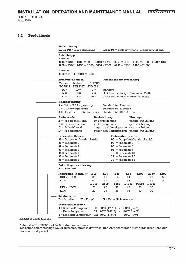
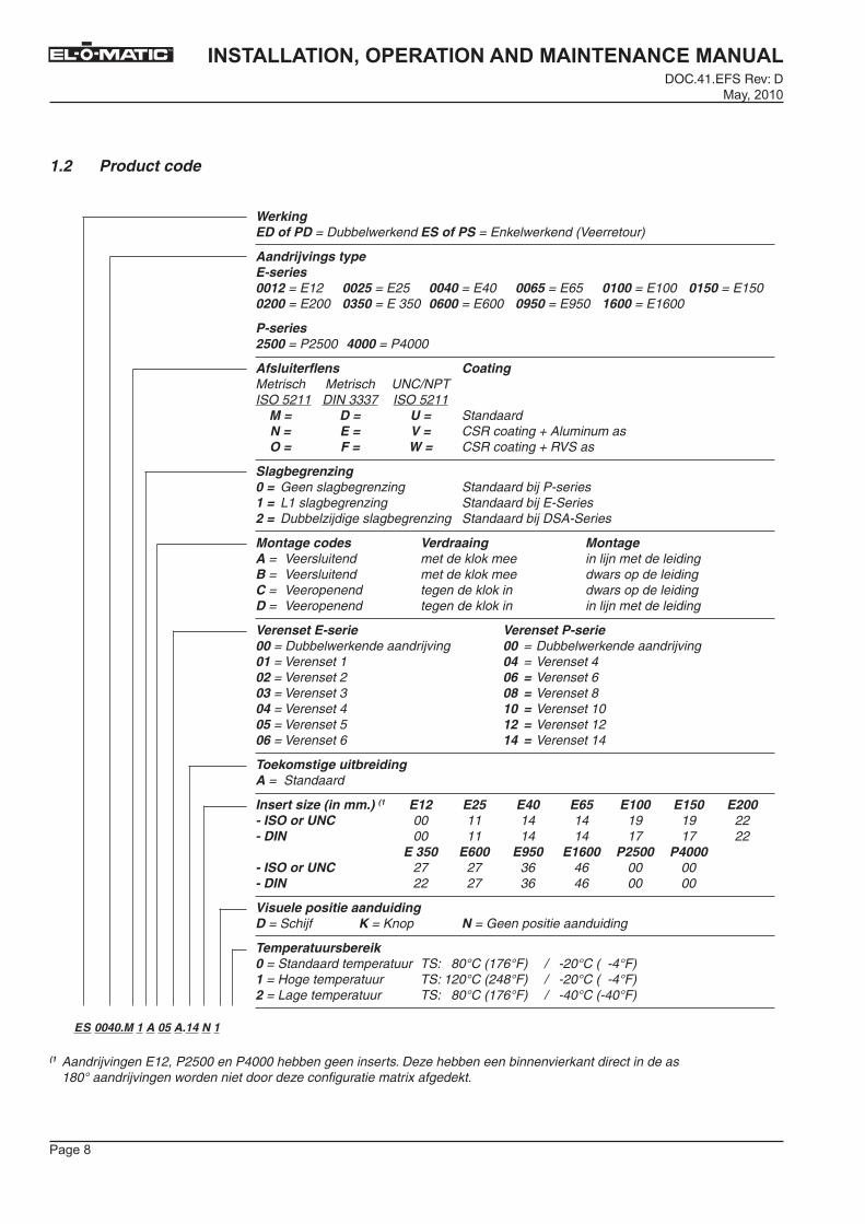
WerkingED of PD = Dubbelwerkend ES of PS = Enkelwerkend (Veerretour)
Aandrijvings typeE-series0012 = E12 0025 = E25 0040 = E40 0065 = E65 0100 = E100 0150 = E1500200 = E200 0350 = E 350 0600 = E600 0950 = E950 1600 = E1600
P-series2500 = P2500 4000 = P4000
Afsluiterflens Coating Metrisch Metrisch UNC/NPT ISO 5211 DIN 3337 ISO 5211 M = D = U = Standaard N = E = V = CSR coating + Aluminum as O = F = W = CSR coating + RVS as
Slagbegrenzing0 = Geen slagbegrenzing Standaard bij P-series1 = L1 slagbegrenzing Standaard bij E-Series2 = Dubbelzijdige slagbegrenzing Standaard bij DSA-Series
Montage codes Verdraaing MontageA = Veersluitend met de klok mee in lijn met de leidingB = Veersluitend met de klok mee dwars op de leidingC = Veeropenend tegen de klok in dwars op de leidingD = Veeropenend tegen de klok in in lijn met de leiding
Verenset E-serie Verenset P-serie00 = Dubbelwerkende aandrijving 00 = Dubbelwerkende aandrijving01 = Verenset 1 04 = Verenset 402 = Verenset 2 06 = Verenset 603 = Verenset 3 08 = Verenset 804 = Verenset 4 10 = Verenset 1005 = Verenset 5 12 = Verenset 1206 = Verenset 6 14 = Verenset 14
Toekomstige uitbreidingA = Standaard
Insert size (in mm.) (1 E12 E25 E40 E65 E100 E150 E200- ISO or UNC 00 11 14 14 19 19 22- DIN 00 11 14 14 17 17 22 E 350 E600 E950 E1600 P2500 P4000- ISO or UNC 27 27 36 46 00 00- DIN 22 27 36 46 00 00
Visuele positie aanduidingD = Schijf K = Knop N = Geen positie aanduiding
Temperatuursbereik0 = Standaard temperatuur TS: 80°C (176°F) / -20°C ( -4°F)1 = Hoge temperatuur TS: 120°C (248°F) / -20°C ( -4°F)2 = Lage temperatuur TS: 80°C (176°F) / -40°C (-40°F)
1.2 Product code
ES 0040.M 1 A 05 A.14 N 1
(1 Aandrijvingen E12, P2500 en P4000 hebben geen inserts. Deze hebben een binnenvierkant direct in de as 180° aandrijvingen worden niet door deze configuratie matrix afgedekt.
������
��������������� �������������������������DOC.41.EFS Rev: D�������
TM
2.1
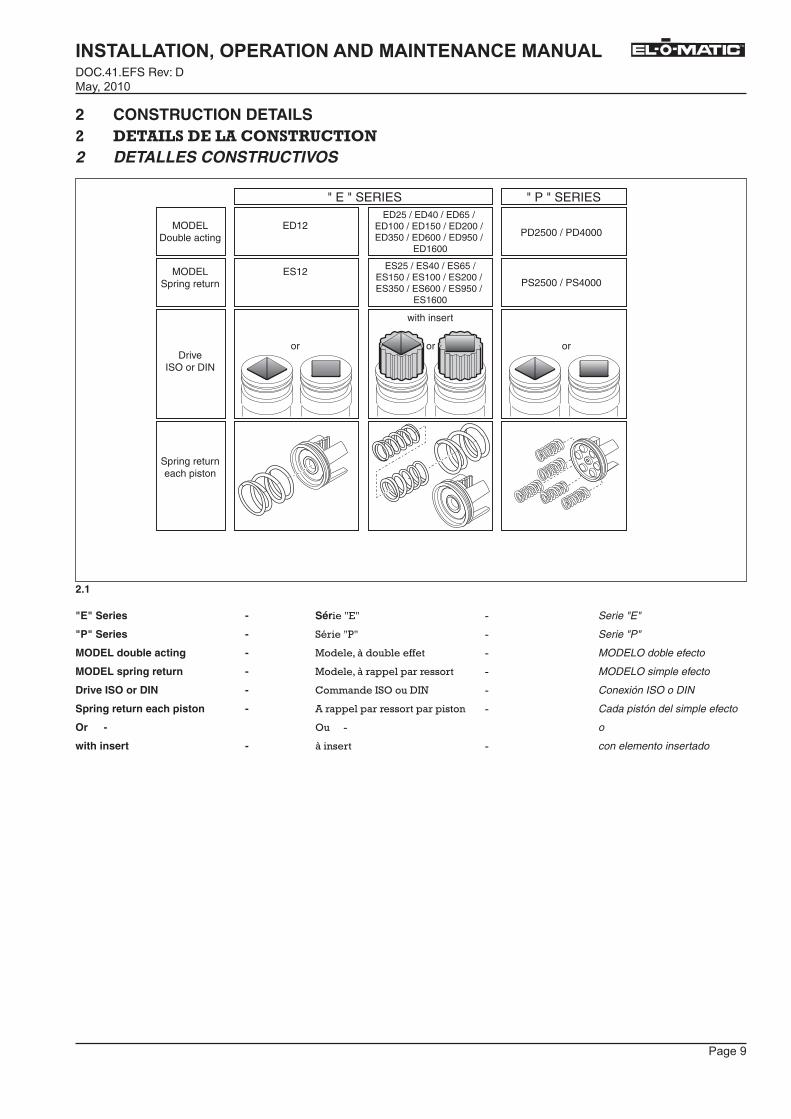
2 CONSTRUCTION DETAILS%� �� �@ ���@ ���� �������2 DETALLES CONSTRUCTIVOS
"E" Series -
"P" Series -
MODEL double acting -
MODEL spring return -
Drive ISO or DIN -
Spring return each piston -
Or -
with insert -
" P " SERIES
PD2500 / PD4000
PS2500 / PS4000
ED25 / ED40 / ED65 / ED100 / ED150 / ED200 / ED350 / ED600 / ED950 /
ED1600
ES25 / ES40 / ES65 /ES150 / ES100 / ES200 / ES350 / ES600 / ES950 /
ES1600
" E " SERIES
ED12
ES12
or oror
with insert
MODELDouble acting
MODELSpring return
DriveISO or DIN
Spring returneach piston
Sér��&'&�
%� ��&(&�
������+����,������
������+� ������� � ��� ��
!�������=%>����-=:�
�� ������� � ��� ���� ��������
>��
+���� ��
Serie "E"
Serie "P"
MODELO doble efecto
MODELO simple efecto
Conexión ISO o DIN
Cada pistón del simple efecto
o
con elemento insertado
�
�������
��������������� �������������������������DOC.41.EFS Rev: D
�������
TM
3 PRINCIPLES OF OPERATION )� ��// ���)� ��������� ���2����� /�����
3.1.1
3.1.2
A
BA
Code A + B
B
BA
Code A + B
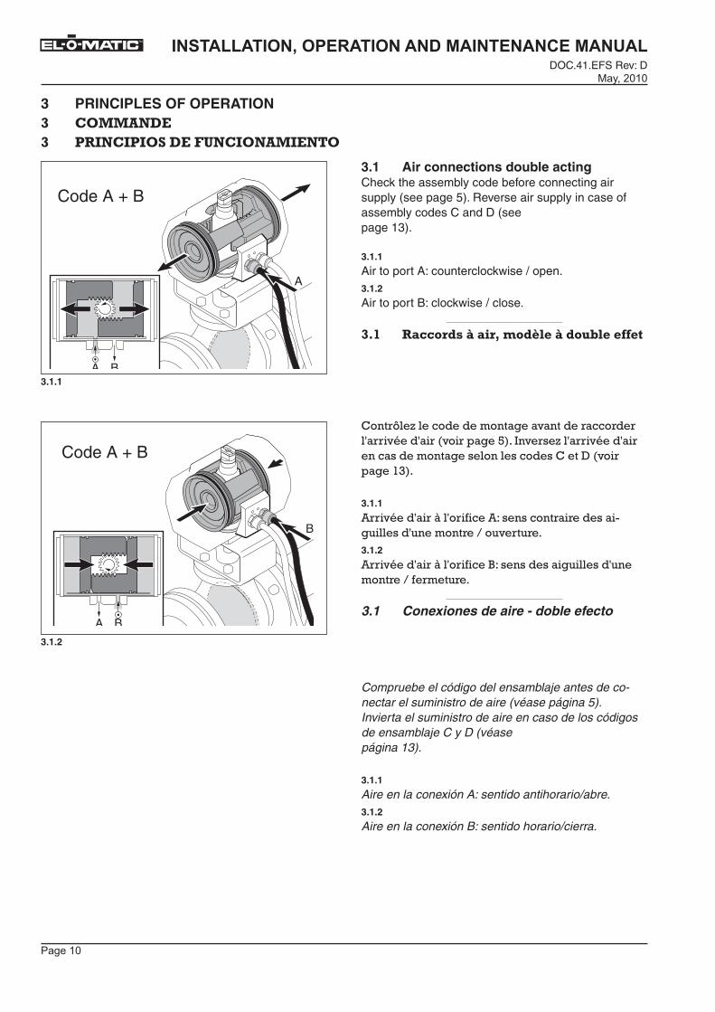
3.1 Air connections double actingCheck the assembly code before connecting air supply (see page 5). Reverse air supply in case of assembly codes C and D (see page 13).
3.1.1
Air to port A: counterclockwise / open.3.1.2
Air to port B: clockwise / close.
)=�� �+����5��A�+��B���5C-��A�5��!-���,,��
!��� L�E����������������������� �� � ���� �������� ����� �����4���=�� �E���� �������� ���������������������������!���-����� �����#$��
3.1.1
� �������� �+���� �����J�������� �� ������ ���������������� �;���� �� �3.1.2
� �������� �+���� ����@J�������������������������� �;�� ��� �
3.1 Conexiones de aire - doble efecto
Compruebe el código del ensamblaje antes de co-nectar el suministro de aire (véase página 5).Invierta el suministro de aire en caso de los códigos de ensamblaje C y D (véase página 13).
3.1.1
Aire en la conexión A: sentido antihorario/abre.3.1.2
Aire en la conexión B: sentido horario/cierra.�

�������
��������������� �������������������������DOC.41.EFS Rev: D�������
TM
A
A
Code A + B
A
Code A + B
3.2.1
3.2.2
3.2 Air connections spring return Check the assembly code before connecting air supply (see page 5). Reverse air supply in case of assembly codes C and D (see page 13).
3.2.1
Air to port A: counterclockwise / open.3.2.2
Spring return: clockwise / close.
)=%� �+����5��A�+��B���5C-��A��+##�-�#+���������
!��� L�E����������������������� �� � ���� �������� ����� �����4���=�� �E���� �������� ���������������������������!���-����� �����#$��
3.2.1
� �������� �+���� �����J�������� �� ������ ���������������� �;���� �� �3.1.2
)������� � ��� �J�������������������������� �;�� ��� �
3.2 Conexiones de aire - simple efectoCompruebe el código del ensamblaje antes de co-nectar el suministro de aire (véase página 5).Invierta el suministro de aire en caso de los códigos de ensamblaje C y D (véase página 13).
3.2.1
Aire en la conexión A: sentido antihorario/abre.3.2.2
Retorno por muelles: sentido horario/cierra.
�������
��������������� �������������������������DOC.41.EFS Rev: D
�������
TM
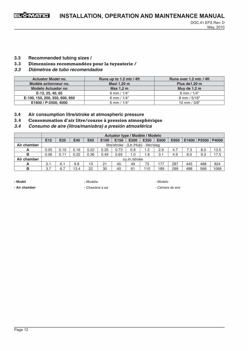
3.3 Recommended tubing sizes / )=)� ����������������+�5D���#����-+���"+���������3.3 Diámetros de tubo recomendados
Actuator Model no. Runs up to 1.2 mtr / 4ft Runs over 1.2 mtr. / 4ftModèle actionneur no. Maxi 1,20 m Plus de1,20 mModelo Actuador no Max 1,2 m Muy de 1,2 m
E-12, 25, 40, 65 6 mm / 1/4" 6 mm / 1/4"E-100, 150, 200, 350, 600, 950 6 mm / 1/4" 8 mm / 5/16"
E1600 / P-2500, 4000 6 mm / 1/4" 10 mm / 3/8"
3.4 Air consumption litre/stroke at atmospheric pressure)='� �������+�����5E+���-������������A�#��������+����#�D��F��3.4 Consumo de aire (litros/maniobra) a presión atmosférica
Actuator type / Modèle / ModeloE12 E25 E40 E65 E100 E150 E200 E350 E600 E950 E1600 P2500 P4000
Air chamber litre/stroke - (Ltr./Hub) - liter/slagA 0.05 0.10 0.16 0.22 0.35 0.73 0.8 1.2 2.9 4.7 7.3 8.0 13.5B 0.06 0.11 0.22 0.36 0.49 0.65 1.0 1.8 3.1 4.9 8.0 9.3 17.5
Air chamber cu.in./strokeA 3.1 6.1 9.8 13 21 45 49 73 177 287 445 488 824B 3.7 6.7 13.4 22 30 40 61 110 189 299 488 568 1068
- Model ������� - Modelo
- Air chamber �!���, �+��� � - Cámara de aire
�

������
��������������� �������������������������DOC.41.EFS Rev: D�������
TM
Spring to close X=ShaftAxeEje
Code A (standard)
Standard
Y=PistonPistonPistón
Standard
Z=ValveVanneVálvula
Closed
Standard+90 ClosedCode B
A B
XY
XY
21
A
B
21
Z
Z
X=
Code C Standard
Y= Z=
Open
+90 OpenCode D +180
Shaftrotation
Rotacióneje
Rotationd’axe
1 =Pressure on
A-port2 =
Pressure on B-port /
Springstroke
1 =Presión sobre
puerto A2 =
Presión sobre puerto B/
Carrera de losressort
1 =Pression àl’orifice A
2 =Pression àl’orifice B /
Course ressort
+180
Spring to open
Z
A B
12
A
B
12
XY
XY
Z
4 ASSEMBLY CODES'� ��� ���/��� G�4 CÓDIGOS DE MONTAJE
4.1 Spring to close (rotation CW, topview) /
1 ��� ��� � ��� ��� ��������������������� �� �������L������� �� ��;�
Muelles cierran (rotación en sentido horario, vista superior)
4.2 Spring to open (rotation CCW) /
>�� �� ��� � ��� ��� ������������������������� �� ��;�
Muelles abren (rotación en sentido anti-horario)
�������
��������������� �������������������������DOC.41.EFS Rev: D
�������
TM
1 2
4.1.1
4.1.2
4.1.3
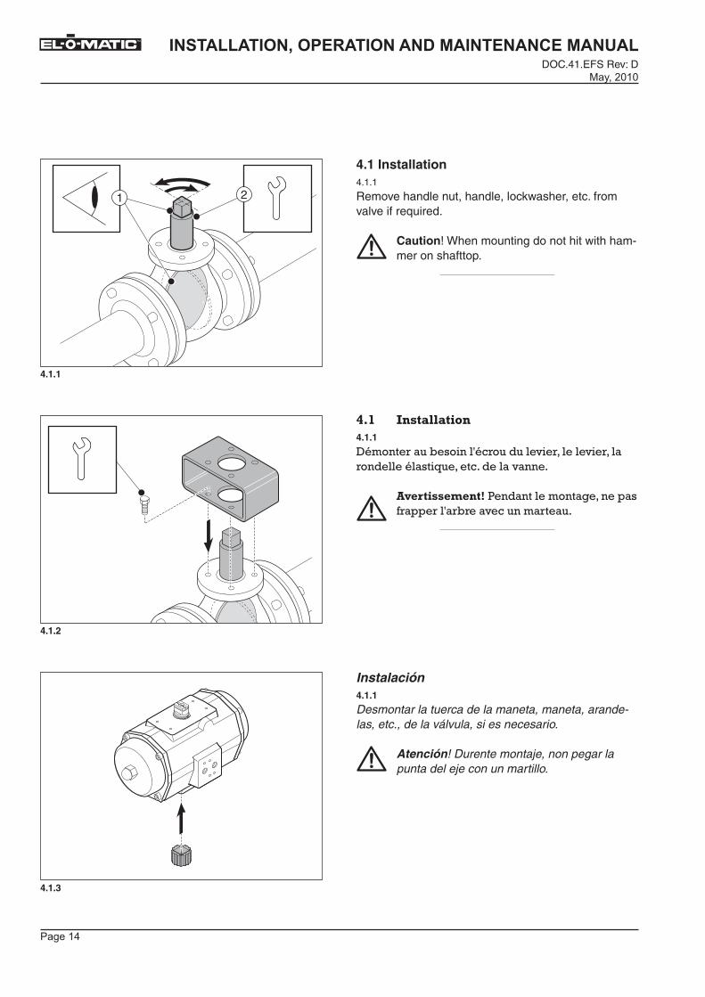
4.1 Installation 4.1.1
Remove handle nut, handle, lockwasher, etc. from valve if required.
Caution! When mounting do not hit with ham-mer on shafttop.
'=�� ����+--+����4.1.1
-����� ����,�������� ��������� ������� ����� �����������������������������
��������������(����������������������� ��� ���� , ��������� ����
Instalación4.1.1
Desmontar la tuerca de la maneta, maneta, arande-las, etc., de la válvula, si es necesario.
Atención! Durente montaje, non pegar la punta del eje con un martillo.
�������
��������������� �������������������������DOC.41.EFS Rev: D�������
TM
OK !
OK !
4.1.4
4.1.5
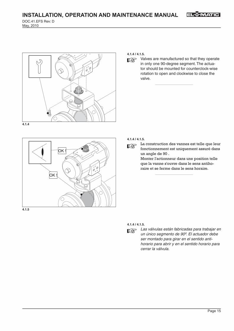
4.1.4 / 4.1.5.
Valves are manufactured so that they operate in only one 90-degree segment. The actua-tor should be mounted for counterclock-wise rotation to open and clockwise to close the valve.
4.1.4 / 4.1.5.
F������ ��������������������������� ����������������������������� �����������������86������ ���������� �������������������������������������� ������������������ �� ������ ��������������� �� �
4.1.4 / 4.1.5.
Las válvulas están fabricadas para trabajar en un único segmento de 90º. El actuador debe ser montado para girar en el sentido anti-horario para abrir y en el sentido horario para cerrar la válvula.
�������
��������������� �������������������������DOC.41.EFS Rev: D
�������
TM
4.2.2
4.2.3
91
80
91.5
-0.5
Closed
OpenL1
93˚
80˚
96˚
-3˚15˚
Open
ClosedDSA
4.2.1
L1
DSA
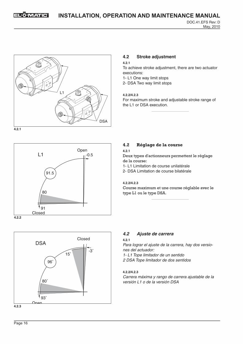
4.2 Stroke adjustment 4.2.1
To achieve stroke adjustment, there are two actuator executions:1- L1 One way limit stops2- DSA Two way limit stops
4.2.2/4.2.3
For maximum stroke and adjustable stroke range of the L1 or DSA execution.
'=%� �D�-+���5��-+�������4.2.1
-����M������������ ��� �������� ������������� �J1- L1 Limitation de course unilatérale2- DSA Limitation de course bilatérale
4.2.2/4.2.3
!�� ����������������� �� ����,��������M��F#�������M��-%��
4.2 Ajuste de carrera4.2.1
Para lograr el ajuste de la carrera, hay dos versio-nes del actuador:1- L1 Tope limitador de un sentido 2 DSA Tope limitador de dos sentidos
4.2.2/4.2.3
Carrera máxima y rango de carrera ajustable de la versión L1 o de la versión DSA�

�������
��������������� �������������������������DOC.41.EFS Rev: D�������
TM
4.2.4
4.2.5
4.2.1 L1 one way stroke adjustment The L1 one way stroke adjustment limits the outward movement of the pistons (see fig. 4.2.4). The double acting and the single acting actuators both have limit stop bolts in the end caps.
Procedure:1. Mount the actuator on the valve (see chapter 4).2. Remove nut covers, loosen the lock nuts and turn
out the limit stop bolts 4 turns (see fig. 4.2.5). Se-lect tool from table (see page 23).
'=%=�� �D�-+���5��-+�-����+�����5������������-+7�D�+-��@�
F����������������� ��������� �������������� ��������� ������������������ ������5�3�5���F���������� �����,���������������������������������� ������,������������������������ ���������������
/D���5�H#�� ����E���������� ��� ������������� ������ �
5��3�� )�� E����� ����������������� E���5�
��� �����,������������������������ ������5�3�4���%�������E������������ ��������������,�������� �����3$��
4.2.1 Ajuste de carrera de un sentido L1El ajuste de carrera de un sentido L1 limita el movi-miento hacia fuera de los pistones (véasefig. 4.2.4). Los actuadores de doble acción y de sim-ple acción tienen los tornillos topes en lastapas laterales.
Procedimiento:1. Monte el actuador sobre la válvula (véase el capí-
tulo 4).2. Retire los protectores de tuerca, afloje las con-
tratuercas y gire los tornillos topes cuatro vueltas hacia fuera (véase fig. 4.2.5). Seleccione herra-mienta de la tabla (véase pág. 23).
�

�������
��������������� �������������������������DOC.41.EFS Rev: D
�������
TM
4.2.6
4.2.7
A
3. Turn actuator shaft until the valve is in the desired position (see fig. 4.2.6). Use some pressure on the "A" port. Use a wrench for accurate positioning.
4. Turn in both the limit stop bolts until an obstruc-tion is felt (do not force) and lock the lock nut and place the nut covers (see fig. 4.2.7). Select tool from table (see page 23).
$��<�� �E���������������� �"�����+���������������� ��������������������� ��������� �����5�3�7����������E���� ������ �������� ���� �������9�����E���������� ������������ ������ ����
5��% E��������,��������������������"�����+��������������E���� ������������� E�������� E���� �����,������� ����E������������� ������5�3�?���%�������E������������ ��������������,�������� �����3$��
3. Gire el eje del actuador hasta que la válvula esté en la posición deseada (véase fig. 4.2.6)
Use un poco de presión en la conexión "A" Use una llave de tuercas para colocar con precisión.
4. Gire los dos tornillos topes hasta que se note una obstrucción (no lo fuerce), bloquee la contratuerca y coloque los protectores de tuerca (véase fig. 4.2.7). Seleccione herramienta de la tabla (véase pág. 23).
�
�������
��������������� �������������������������DOC.41.EFS Rev: D�������
TM
4.2.8
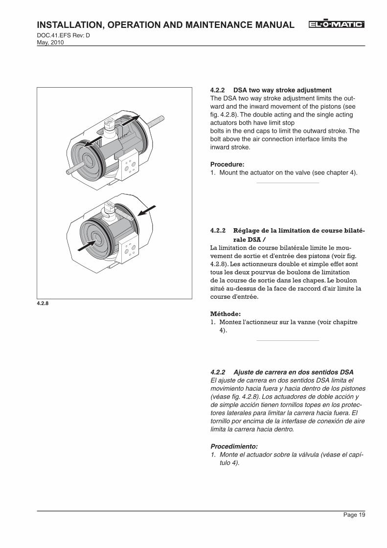
4.2.2 DSA two way stroke adjustmentThe DSA two way stroke adjustment limits the out-ward and the inward movement of the pistons (see fig. 4.2.8). The double acting and the single acting actuators both have limit stopbolts in the end caps to limit the outward stroke. The bolt above the air connection interface limits the inward stroke.
Procedure:1. Mount the actuator on the valve (see chapter 4).
'=%=%� �D�-+���5��-+�-����+�����5���������!�-+�D7�+-�� ��
F����������������� ��,����� �������������� ��������� ��������� ����������������� ������5�3�I���F��������� �����,���������������������������������� ������,��������������������������� ������ �����������������F�,�������������� ���������������� �� ������ ������������ ������ ��
/D���5�H#�� ����E���������� ��� ������������� ������ �
5��
4.2.2 Ajuste de carrera en dos sentidos DSAEl ajuste de carrera en dos sentidos DSA limita el movimiento hacia fuera y hacia dentro de los pistones (véase fig. 4.2.8). Los actuadores de doble acción y de simple acción tienen tornillos topes en los protec-tores laterales para limitar la carrera hacia fuera. El tornillo por encima de la interfase de conexión de aire limita la carrera hacia dentro.
Procedimiento:1. Monte el actuador sobre la válvula (véase el capí-
tulo 4).
�������
��������������� �������������������������DOC.41.EFS Rev: D
�������
TM
4.2.10
4.2.9
A
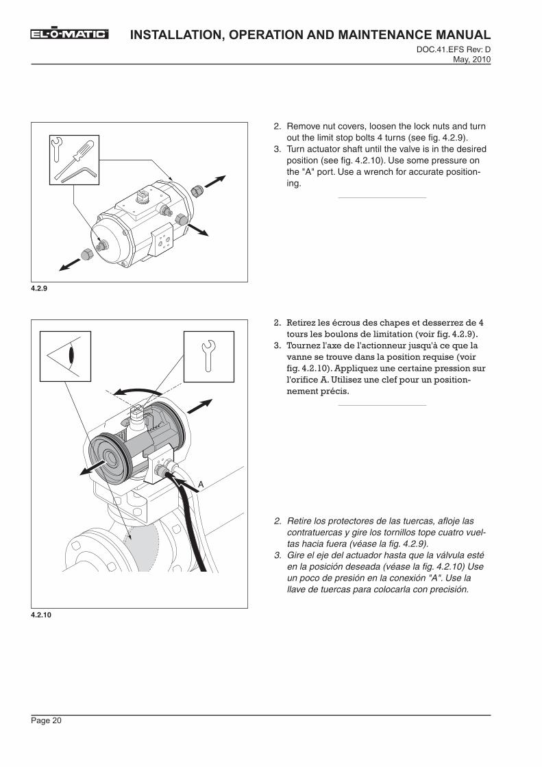
2. Remove nut covers, loosen the lock nuts and turn out the limit stop bolts 4 turns (see fig. 4.2.9).
3. Turn actuator shaft until the valve is in the desired position (see fig. 4.2.10). Use some pressure on the "A" port. Use a wrench for accurate position-ing.
3�� )�� E����� ����������������� E���5���� �����,������������������������ ������5�3�8��
$�� <�� �E����������������� �"�����+���������������� ��������������������� ��������� ������5�3�#6����������E���� ������ �������� ���� �������9�����E���������� ������������ ������ ����
2. Retire los protectores de las tuercas, afloje las contratuercas y gire los tornillos tope cuatro vuel-tas hacia fuera (véase la fig. 4.2.9).
3. Gire el eje del actuador hasta que la válvula esté en la posición deseada (véase la fig. 4.2.10) Use un poco de presión en la conexión "A". Use la llave de tuercas para colocarla con precisión.
�
�������
��������������� �������������������������DOC.41.EFS Rev: D�������
TM
4.2.12
4.2.11
B
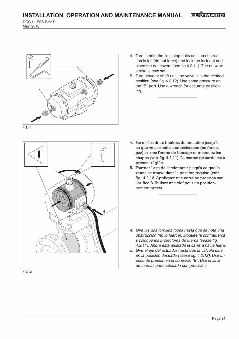
4. Turn in both the limit stop bolts until an obstruc-tion is felt (do not force) and lock the lock nut and place the nut covers (see fig 4.2.11). The outward stroke is now set.
5. Turn actuator shaft until the valve is in the desired position (see fig. 4.2.12). Use some pressure on the "B" port. Use a wrench for accurate position-ing.
5�� % E��������,��������������������"�����+��������������E���� ������������� E�������� E���� �����,������� ����E������������� ������5�3�##���F���� ������ ������+�� ����� �����
4�� <�� �E����������������� �"�����+���������������� ��������������������� ��������� �������5�3�#3���������E���� ������ �������� ���� ����@��9�����E���������� ������������ ������ ����
4. Gire los dos tornillos topes hasta que se note una obstrucción (no lo fuerce), bloquee la contratuerca y coloque los protectores de tuerca (véase fig. 4.2.11). Ahora está ajustada la carrera hacia fuera.
5. Gire el eje del actuador hasta que la válvula esté en la posición deseada (véase fig. 4.2.12). Use un poco de presión en la conexión "B". Use la llave de tuercas para colocarla con precisión.
�

�������
��������������� �������������������������DOC.41.EFS Rev: D
�������
TM
4.2.13
6. Turn in the limit stop bolt until an obstruction is felt (do not force), lock the lock nut and place the nut covers (see fig 4.2.13). The inward stroke is now set.
7�� % E���,�������������������"�����+��������������E���� ������������� E�������� E���� �����,������� ����E������������ ������5�3�#$���F���� ������ �����+�� ����� �����
6. Gire el tornillo tope hasta que se note una obs-trucción (no lo fuerce), bloquee la contratuerca y coloque el protectore de tuerca (véase fig. 4.2.13). Ahora está ajustada la carrera hacia dentro.
�
������
��������������� �������������������������DOC.41.EFS Rev: D�������
TM
4.3 Tool table'=)� �+!-�+������--+��4.3 Tabla de herramientas
L1 limit stop bolts (in endcaps)Actuator type Nut Bolt Actuator type Nut Bolt
ED25 W 10 mm AK 3 mm ED600 / 950 W 24 mm W 11 mmED40 / 65 W 13 mm AK 4 mm ED1600 W 30 mm W 11 mm
ED100 / 150 / 200 W 17 mm AK 5 mm PD2500 W 46 mm W 17 mmED350 W 19 mm AK 6 mm PD4000 W 46 mm W 17 mm
ES25 / 40 W 10 mm SD 1.0x5.5 mm ES600 / 950 W 24 mm W 11 mmES65 / 100 W 13 mm SD 1.0x5.5 mm ES1600 W 30 mm W 11 mmES150 / 200 W 17 mm SD 1.2x8.0 mm PS2500 W 46 mm W 17 mm
ES350 W 19 mm SD 1.2x8.0 mm PS4000 W 46 mm W 17 mm
DSA Limit stop bolt (above air connection interface)Actuator type Nut Bolt Actuator type Nut Bolt
E25 W 10 mm SD 1.0x5.5 mm E200 / 350 W 19 mm SD 1.2x8.0 mmE40 / 65 W 13 mm SD 1.0x5.5 mm E600 / 950 W 24 mm W 11 mm
E100 / 150 W 17 mm SD 1.2x8.0 mm E1600 W 30 mm W 11 mm
Limit stop bolt : Boulon de limitation de course : Tornillo tope
Endcap : Couvercle : Tapa lateral
Actuator type : Type actionneur : Tipo actuador
Nut : Ecrou : Tuerca
Bolt : Vis : Tornillio limitador
AK = Allen key : AK = Clé pour vis à six pans creux : AK = Llave Allen
SD = Screwdriver : SD = Tournevis : SD = Destornillador
W = Wrench : W = Serre-écrou : W = Llave de tuercas

�������
��������������� �������������������������DOC.41.EFS Rev: D
�������
TM
5 DISASSEMBLY&� I/��� G�5 DESARME DEL ACTUADOR
3
1
2
5.1.1
5.1.2
5.1 Before starting 5.1.1
Caution! Never disassemble a valve that is under pressure!
Caution! Ball valves and plug valves can trap pressurized media in the cavity. Isolate the piping system in which the actuator valve as-sembly is mounted and relieve any pressure on the valve.
&=�� ��D#+�+�����5.1.1
��������������:�������E�"�������������������� �����N
��������������F��������+�,������+�,��� ���������� ��� ����������������� � ����������������, ��=��� ������M��� ���O������������������� ������ ��� �� ���������
5.1 Antes de empezar5.1.1
¡ Atención ! No desmontar nunca una válvula que esté bajo presión.
Precaución: las válvulas de bola y de macho pueden retener el medio presurizado en su cavidad. Aislar el sistema de tuberías donde esté montada la válvula y eliminar cualquier presión en la válvula.

�������
��������������� �������������������������DOC.41.EFS Rev: D�������
TM
ED
ES
5.2.1
5.2.2
5.2.3
5.2 Removing endcaps type ES/ED 25 to 3505.2.1 / 5.2.2 / 5.2.3
Be careful not to damage the endcap O-rings.
Caution! If the actuator is a "spring return" model, uniformly loosen all endcaps screws, two to three turns at a time, in sequence, to relieve pre-load of the springs. On all actua-tors with springs use caution when removing endcaps.
&=%� D����+���5����������-����"#��� ���%&��J��F�EA�)&$�
5.2.1 / 5.2.2 / 5.2.3
P� �+�������������� ����"�������� ����������� ��
������������N�-��������������������� �&+� ������� � ��� �&����� �������������������� �������� ��������� ��������� ������� ��+������������� �������� ����� �� ����� ���� �������� ��� ����(�� ���������������� ��+� ������� � ��� �����ME�� ����������������������� ���
5.2 Desmontaje de las tapas laterales tipo ES/ED 25 hasta 350
5.2.1 / 5.2.2 / 5.2.3
Tener cuidado de no dañar las juntas tóricas de las tapas laterales.
¡ Atención ! Si el actuador es un actuador de "simple efecto", aflojar uniformemente todos los tornillos de cada tapa lateral con dos o tres vueltas cada vez, en secuencia, con el fin de rebajar la tensión de los muelles. En todos los actuadores de retorno por muelles (simple efecto) debe irse con cuidado al desmontar las tapas laterales.
�
�������
��������������� �������������������������DOC.41.EFS Rev: D
�������
TM
5.3.1
5.3.2
1
2 1
1
12 2
2
11
2
2
2
1 1
2P
1 1
2
P2500 / P4000
2 1
1 2
1
P500 / P750 / P1100
ES 600 / 950 / 1600
2
2
P
E
5.3 Removing endcaps Type PE or PS 5.3.1 / 5.3.2
Caution! If the actuator is a "spring return" model, first loosen screws 1, then uniformly loosen all endcap screws 2, two to three turns at a time, in sequence, to relieve pre-load of the springs. On all actuators with springs use caution when removing endcaps.
&=)� D����+���5����������-��B��"#��������� �
5.3.1 / 5.3.2
��������������-������������������� �� �&+� ������� � ��� �&����� ����,� ���������#����� ��������������������3������� �������� ��������� ��������� ������� ��+������������� �������� ������� ����� ���� �������� ��� ����(�� ���������������� ��+� ������� � ��� �����ME�� � ���������������������� ���
5.3 Desmontaje de las tapas laterales, Tipo PE o PS
5.3.1 / 5.3.2
¡ Atención ! Si el actuador es un actuador de "simple efecto", soltar primero los tornillos número 1, para después aflojar uniforme-mente los tornillos número 2 de cada tapa lateral con dos o tres vueltas cada vez, en secuencia, con el fin de rebajar la tensión de los muelles. En todos los actuadores de retorno por muelles (simple efecto) debe irse con cuidado al desmontar las tapas laterales.
�������
��������������� �������������������������DOC.41.EFS Rev: D�������
TM
5.4 Removing Pistons/Spindle, E- and P-series
5.4.1
The two pistons can now be removed by rotat-ing the actuator shaft.
5.4.2
In case of a DSA actuator first remove the DSA cam through the bore of the housing. Then take out the shaft.
2
21
5.4.1
5.4.2
2
3
DSA
1
P-Series
E-Series
Std
&='� D����+���5���#�������+K�B��D�����������
5.4.1
F������������������������������Q� ������������ �������� , ������������ �
5.4.2
-��������������������� �-%��� �� ����,� ��������-%���� ���� ��������������%� �� ���������� , �
5.4 Desmontaje de los Pistones/Eje, series P y E
5.4.1
Los dos pistones pueden ser desmontados ahora girando el eje del actuador, conduci-endo los pistones hacia afuera hasta que los dentados del pistón y el eje se hayan desen-granado.
5.4.2
En caso de un actuador DSA retirar primero la leva DSA a través del taladro del alojamiento. A continua-ción sacar el eje.
�������
��������������� �������������������������DOC.41.EFS Rev: D
�������
TM
1
2
3
45
5.5.1
�5.5 Removing insert5.5.1
Insert removal requires the use of the extrac-tor part No. 590.00.001 for square sizes 11, 14 and 17. Part No. 590.00.002 is used for square sizes 19, 22 and 27.
&=&� D����+���5��-E������5.5.1
F����������������� ���������������������� ��� ��������� ���486�66�66#���� ����� ���##��#5���#?�F�������������� ���486�66�663���������������� ���#8��33���3?�
5.5 Extracción del elemento insertado5.5.1
La extracción del elemento insertado requiere el uso de la pieza extractora Nº 590.00.001 para los tamaños cuadrados 11, 14 y 17.La pieza Nº 590.00.002 se usa para los tama-ños cuadrados 19, 22 y 27.
�������
��������������� �������������������������DOC.41.EFS Rev: D�������
TM
CASTROL LMX or FINA CERAN WR2(or equal)
�
P-Series
E-Series
6.1.1
6.1.2
6.1.3
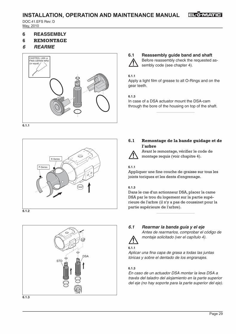
6 REASSEMBLY(� ��/��� G�6 REARME
STD
DSA
6.1 Reassembly guide band and shaft Before reassembly check the requested as-
sembly code (see chapter 4).
6.1.1
Apply a light film of grease to all O-Rings and on the gear teeth.
6.1.3
In case of a DSA actuator mount the DSA-cam through the bore of the housing on top of the shaft.
(=�� ������+���5��-+�!+�5�����5+������5��-E+�!���������� ���������� ��� ��������������� ��������� ������ �5��
6.1.1
������� ��������������� ������� ���������"�������� ������������������� ����
6.1.3
-��������������������� �-%������ �������-%���� ���� ��������������� ������ ������� �� ������ , �������M�������������������� ������ ������� �� ������ , ��
6.1 Rearmar la banda guía y el ejeAntes de rearmarlos, comprobar el código de montaje solicitado (ver el capítulo 4).
6.1.1
Aplicar una fina capa de grasa a todas las juntas tóricas y sobre el dentado de los engranajes.
6.1.3
En caso de un actuador DSA montar la leva DSA a través del taladro del alojamiento en la parte superior del eje (no hay soporte para la parte superior del eje).
����� �
��������������� �������������������������DOC.41.EFS Rev: D
�������
TM
6.2.1
6.2.2
6.2.3
c dc=d
ok !
ok !
90°
FINA CERAN WR2(or equal)
TYPESERIAL No.
ED-100/A
10 BAR
9630220004
Holland 074-2436545
a
ba = b
ED-100/A
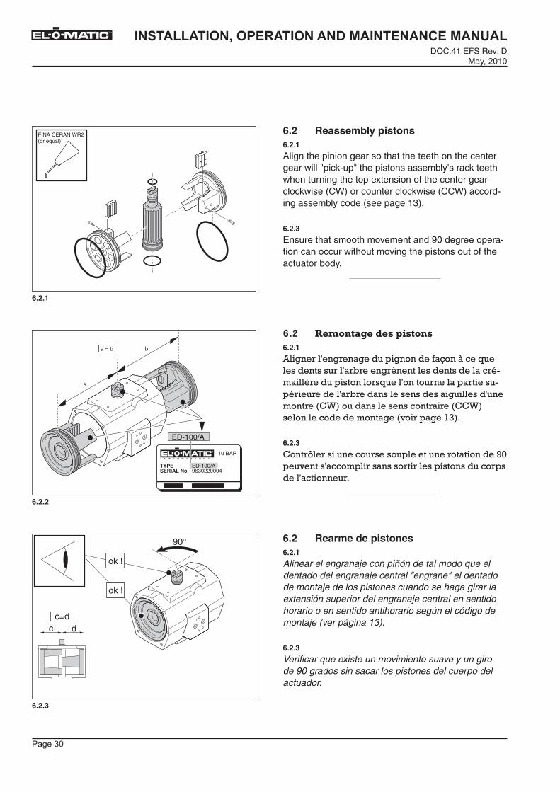
6.2 Reassembly pistons 6.2.1
Align the pinion gear so that the teeth on the center gear will "pick-up" the pistons assembly's rack teeth when turning the top extension of the center gear clockwise (CW) or counter clockwise (CCW) accord-ing assembly code (see page 13).
6.2.3
Ensure that smooth movement and 90 degree opera-tion can occur without moving the pistons out of the actuator body.
(=%� ������+���5���#������6.2.1
����� ����� ������������������R���+��������������� ���� , ��� ������������������ � ������ ������������� ������������ ������� ����� �� �� ������ , ��������������������������������� ��!B������������������� �� ��!!B������������������������� �����#$��
6.2.3
!��� L� ��������� ������������� ����������86���������������� �������� �� ���������������� �������������� �
6.2 Rearme de pistones6.2.1
Alinear el engranaje con piñón de tal modo que el dentado del engranaje central "engrane" el dentado de montaje de los pistones cuando se haga girar la extensión superior del engranaje central en sentido horario o en sentido antihorario según el código de montaje (ver página 13).
6.2.3
Verificar que existe un movimiento suave y un giro de 90 grados sin sacar los pistones del cuerpo del actuador.�
����� �
��������������� �������������������������DOC.41.EFS Rev: D�������
TM
6.3.1
6.3.2
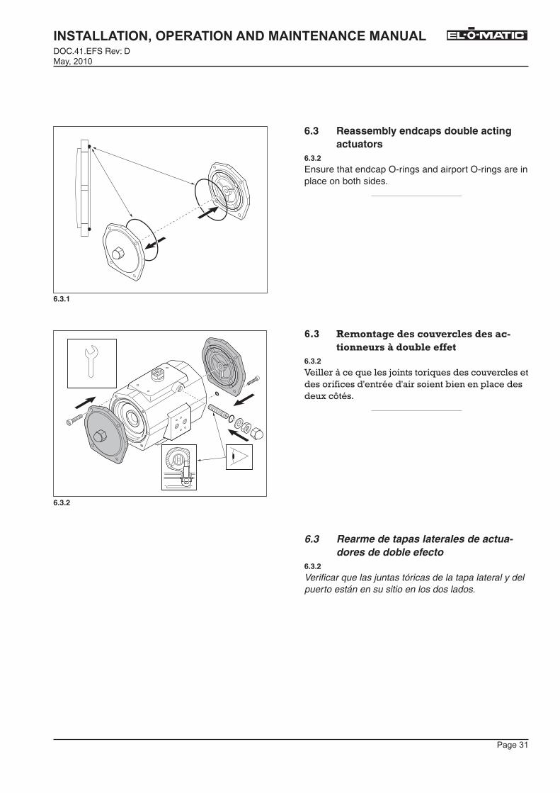
6.3 Reassembly endcaps double acting actuators
6.3.2
Ensure that endcap O-rings and airport O-rings are in place on both sides.
(=)� ������+���5����������-���5���+�7����������A�5��!-���,,���
6.3.2
S��� �+��������"�������� ����������� ��������� ��������� ������ �������,����������������L����
6.3 Rearme de tapas laterales de actua-dores de doble efecto
6.3.2
Verificar que las juntas tóricas de la tapa lateral y del puerto están en su sitio en los dos lados.�
����� �
��������������� �������������������������DOC.41.EFS Rev: D
�������
TM
6.4.3
N-1 N-2
N-3 N-4
N-5 N-6
6.4.2
6.4.1
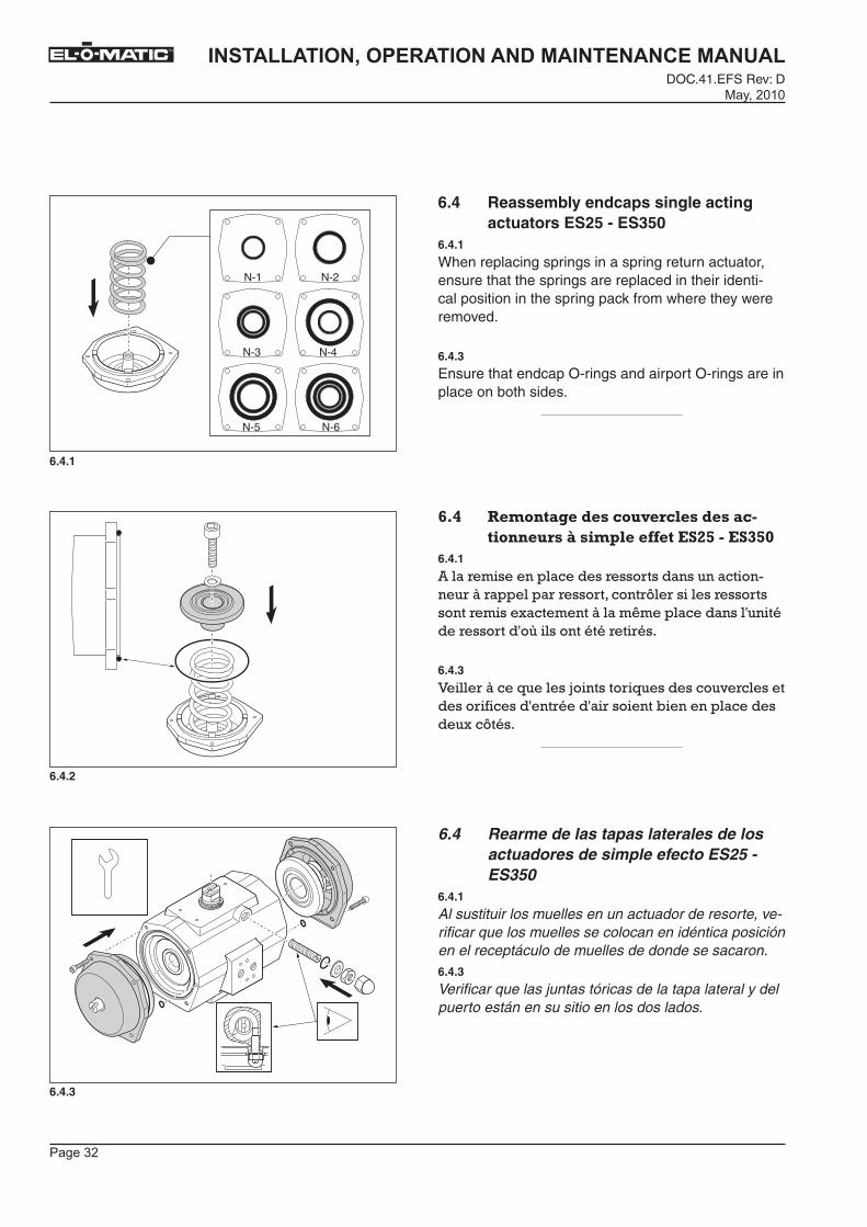
6.4 Reassembly endcaps single acting actuators ES25 - ES350
6.4.1
When replacing springs in a spring return actuator, ensure that the springs are replaced in their identi-cal position in the spring pack from where they were removed.
6.4.3
Ensure that endcap O-rings and airport O-rings are in place on both sides.
(='� ������+���5����������-���5���+�7����������A����#-���,,���� %&�7�� )&$
6.4.1
����� ������������� ��� ���������������� �� �+� ������� � ��� ������ L� ������� ��� �������� �����������+�����Q��������������������� ��� �����O������������� �� ���
6.4.3
S��� �+��������"�������� ����������� ��������� ��������� ������ �������,����������������L����
6.4 Rearme de las tapas laterales de los actuadores de simple efecto ES25 - ES350
6.4.1
Al sustituir los muelles en un actuador de resorte, ve-rificar que los muelles se colocan en idéntica posición en el receptáculo de muelles de donde se sacaron.6.4.3
Verificar que las juntas tóricas de la tapa lateral y del puerto están en su sitio en los dos lados.
�����
��������������� �������������������������DOC.41.EFS Rev: D�������
TM
6.5.1
6.5.3
6.5.2
N-1 N-2
N-3 N-4
N-5 N-6
N-4 N-6
N-8 N-10
N-12 N-14
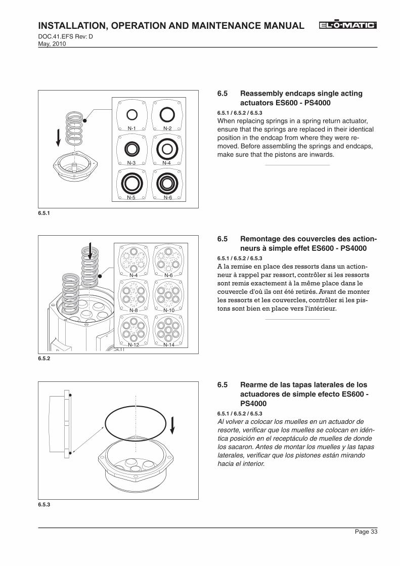
6.5 Reassembly endcaps single acting actuators ES600 - PS4000
6.5.1 / 6.5.2 / 6.5.3
When replacing springs in a spring return actuator, ensure that the springs are replaced in their identical position in the endcap from where they were re-moved. Before assembling the springs and endcaps, make sure that the pistons are inwards.
6.5 Remontage des couvercles des action-neurs à simple effet ES600 - PS4000
6.5.1 / 6.5.2 / 6.5.3
����� ������������� ��� ���������������� �� �+� ������� � ��� ������ L� ������� ��� �������� �����������+�����Q���������������� �����O������������� �� ���������������� ���� ��� ����������� ������� L� ���������� ����������,���������� �������� �� �
6.5 Rearme de las tapas laterales de los actuadores de simple efecto ES600 - PS4000
6.5.1 / 6.5.2 / 6.5.3
Al volver a colocar los muelles en un actuador de resorte, verificar que los muelles se colocan en idén-tica posición en el receptáculo de muelles de donde los sacaron. Antes de montar los muelles y las tapas laterales, verificar que los pistones están mirando hacia el interior.�
����� �
��������������� �������������������������DOC.41.EFS Rev: D
�������
TM
1 1
2 1
1
12 2
2
11
2
2
2
1 1
2P
1 1
2
P2500 / P4000
2 1
1 2
P500 / P750 / P1100
ES600 / 950 / 1600
2
2
6.5.4
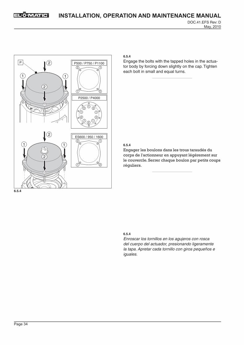
6.5.4
Engage the bolts with the tapped holes in the actua-tor body by forcing down slightly on the cap. Tighten each bolt in small and equal turns.
6.5.4
'���� ����,���������������� ������ ���������� �������������� �������M�������� ������ ������ ���% ������,�������� ������������ ����� ��
6.5.4
Enroscar los tornillos en los agujeros con rosca del cuerpo del actuador, presionando ligeramente la tapa. Apretar cada tornillo con giros pequeños e iguales.
����� �
��������������� �������������������������DOC.41.EFS Rev: D�������
TM
6.6.1
6.6.2
1
2
ISO 5211 DIN 3337
90°45°
A B
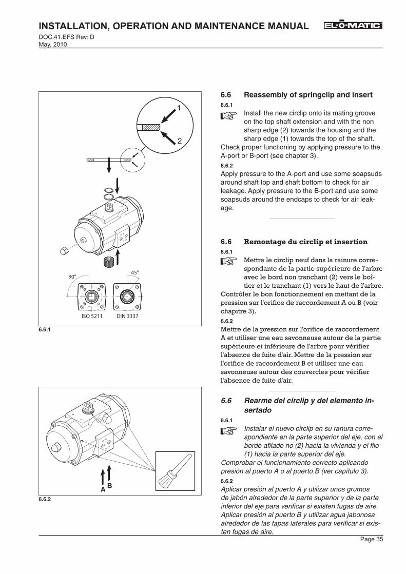
6.6 Reassembly of springclip and insert6.6.1
Install the new circlip onto its mating groove on the top shaft extension and with the non sharp edge (2) towards the housing and the sharp edge (1) towards the top of the shaft.
Check proper functioning by applying pressure to the A-port or B-port (see chapter 3).6.6.2
Apply pressure to the A-port and use some soapsuds around shaft top and shaft bottom to check for air leakage. Apply pressure to the B-port and use some soapsuds around the endcaps to check for air leak-age.
(=(� ������+���5������-�#�������������6.6.1
��� ���� ���������������� ���� �� ���������������� ������� �� ������ , ������,� ������� ��������3��� ����,�T �� ������ ��������#��� �������������� , �
!��� L� ���,������������������������������ �������� ���� ������ �� ����������@����� ������ �$��6.6.2
��� ������� �������� ���� ������ �� ��������������� ��������������������� �������� ������� �� ������� �� ������ , ���� ��� ��� ����,�������������� ����� ������� �������� ���� ������ �� �����@��������� ��������������������� ������� ������ ��� ��� ����,�������������� �
6.6 Rearme del circlip y del elemento in-sertado
6.6.1
Instalar el nuevo circlip en su ranura corre-spondiente en la parte superior del eje, con el borde afilado no (2) hacia la vivienda y el filo (1) hacia la parte superior del eje.
Comprobar el funcionamiento correcto aplicando presión al puerto A o al puerto B (ver capítulo 3).6.6.2
Aplicar presión al puerto A y utilizar unos grumos de jabón alrededor de la parte superior y de la parte inferior del eje para verificar si existen fugas de aire. Aplicar presión al puerto B y utilizar agua jabonosa alrededor de las tapas laterales para verificar si exis-ten fugas de aire.�
����� �
��������������� �������������������������DOC.41.EFS Rev: D
�������
TM
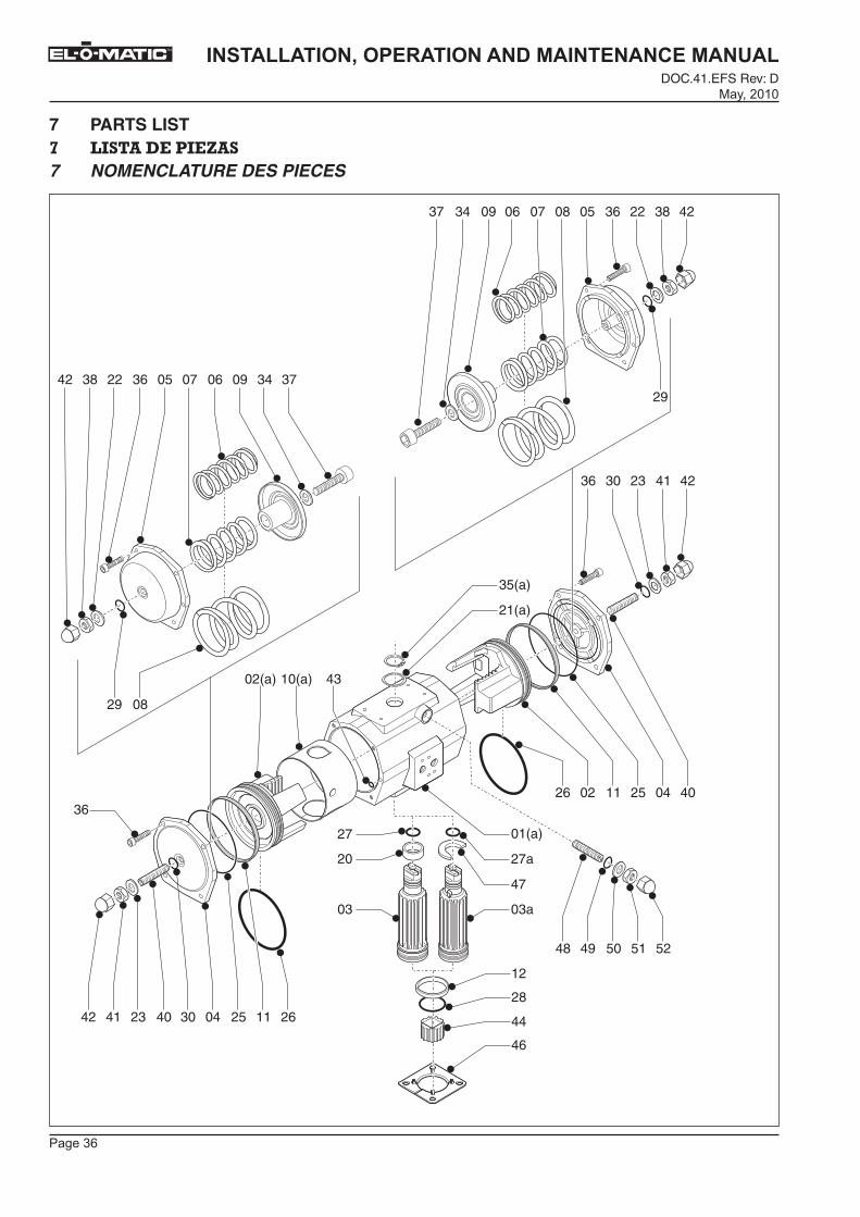
7 PARTS LISTL� @� � ������9 �7 NOMENCLATURE DES PIECES
01(a)
36
27a
35(a)
21(a)
47
03a03
20
27
12
40042511
23 41 423036
223842 070536 34 370906
063437 09 050807 38 422236
0226
0829
29
02(a) 10(a) 43
2611250430
5251504948
40234142
28
44
46

����� �
��������������� �������������������������DOC.41.EFS Rev: D�������
TM
Pos Qty.QtéCtd.
Description Désignation Descripción SpecificationSpécificationSpecificatión
1 1 Body Corps Cuerpo GAISi10Mg, DIN 1725/21a 1 Body DSA Corps DSA Cuerpo DSA GAlSi10Mg, DIN 1725/22 1 Piston Piston Pistón GAISi7Mg, DIN 1725/22a 1 Piston DSA Piston DSA Pistón DSA GAISi7Mg, DIN 1725/23 1 Drive Shaft Arbre de commande Eje AIZnMGCu1.5, DIN 1725/13a 1 Drive Shaft DSA Arbre de commande DSA Eje DSA AIZnMGCu1.5, DIN 1725/14 2 End Cap ED Couvercle ED Tapa lateral ED GDAISi9Cu3, DIN1725/25 2 End Cap ES Couvercle ES Tapa lateral ES GDAISi9Cu3, DIN 725/26 2 Spring-inner Ressort intérieur Muelle interior Class C, DIN 172237 2 Spring-mid Ressort central Muelle medio Class C, DIN 172238 2 Spring-outer Ressort extérieur Muelle exterior Class C, DIN 172239 2 Spring Holder Porte-ressort Soporte muelle C45, DIN 17200
10* 1 Guide Band Bande guidage Banda guia PA66 + MoS210a* 1 Guide Band DSA Bande guidage DSA Banda guia DSA PA66 + MoS211* 2 Guide Band Bandeguidage Banda guia PTFE + 2596 C12* 1 Bearing Bush Coussinet Cojinete cilíndrico PA66 + MoS220* 1 Bearing Bush Coussinet Cojinete cilíndrico POM21* 1 Washer Rondelle Arandela POM21a* 1 Washer DSA Rondelle DSA Arandela DSA POM22* 2 Washer ES Rondelle ES Arandela ES PA623* 2 Washer ED Rondelle ED Arandela ED PA625* 2 O-Ring Joint torique Junta tórica Buna N26* 2 O-Ring Joint torique Junta tórica Buna N27* 2 O-Ring Joint torique Junta tórica Buna N27a* 1 O-Ring DSA Joint torique DSA Junta tórica DSA Buna N28* 2 O-Ring Joint torique Junta tórica Buna N29* 2 O-Ring Joint torique Junta tórica Buna N30* 2 O-Ring Joint torique Junta tórica Buna N34 2 Washer ES Rondelle ES Arandela ES C3535* 1 Spring Clip Circlip Circlip Ck75, DIN 1722235a* 1 Spring Clip DSA Circlip DSA Cierre de resorte DSA Ck75, DIN 1722236 8 End Cap bolt ED/ES Vis de Couvercle ED/ES Tornillo tapa lateral ED/ES AISI 30437 2 Limit Stop Bolt ES Boulon de limitation Tornillo tope de course ES AISI 30438 2 Nut Ecrou Tuerca AlSl 304
40 2 Limit Stop bolt EDBoulon de limitation de course ED
Tornillo limitador lateral ED AlSl 304
41 2 Nut Ecrou Tuerca AlSl 30442 2 Nut cover Chape Protector tuerca PE43* 2 O-Ring Joint torique Junta tórica Buna N44 1 lnsert Insert Elemento insertado AlMgSi 1
46 1Centre-plate (option for DIN3337 actuators)
Plaque de centrage (optio-pour des actionneurs de DIN3337)
Placa centraje (opción para los actuadores de DIN3337)
PA6 + 25% Glass
47 1 Cam for stroke adj. Came de limitation Leva para ajuste AISI 304DSA de course DSA de carrera DSA
48 1 Limit Stop bolt DSABoulon de limitation de course DSA
Tornillo limitador lateral DSA AlSl 304
49* 1 O-Ring DSA Joint torique DSA Junta tórica DSA Buna N50* 1 Washer DSA Rondelle DSA Arandela DSA PA651 1 Nut DSA Ecrou DSA Tuerca DSA AlSl 30452 1 Nut cover DSA Chape DSA Protector tuerca DSA PE
* Recommended Spare Parts (contained in Repair Kit or Repair Kit DSA). The extra or specific parts of a DSA actuator are marked "DSA".
U� (������ ������ ������������������� ������0����� ��� ������������0��� ��� ������-%���� F����������������� ��������������������������� �-%���� ��������������&-%�&�
* Recambios recomendados (incluidos en el Kit de Reparación). Las piezas específicas o extras de un actuador DSA están marcadas "DSA".
7.1 E-serie
����� �
��������������� �������������������������DOC.41.EFS Rev: D
�������
TM
SCHAAL 1:1
01
06
06
23
24
19
10
05
15 260216141703
03171416
250408
080425
2021
0223
24
09
18
����� �
��������������� �������������������������DOC.41.EFS Rev: D�������
TM
7.1 P-serie
Pos Qty.QtéCtd.
Description Désignation Descripción SpecificationSpécificationSpecificatión
1 1 Body Corps Cuerpo GAISi10Mg, DIN 1725/22 2 Piston Piston Pistón GAISi7Mg, DIN 1725/23 2 End Cap PD Couvercle PD Tapa lateral PD GAISi10Mg, DIN 1725/24 2 End Cap PE Couvercle PE Tapa lateral PE GAISi10Mg, DIN 1725/25 1 Central drive shaft Arbre de commande Eje AIZnMGCu1.5, DIN 1725/16 2 Gear Rack Crémaillère Cremallera C45, DIN 172008 14 Spring Ressort Muelle Class C, DIN 172239* 1 Bearing bush Boîte de palier Cojinete eje PA66 + MoS210* 1 Bearing bush Boîte de palier Cojinete eje POM14* 2 Guide band Bande de guidage Banda guia PTFE + 25% C15* 2 Guide band Bande de guidage Banda guia PTFE + 25% C16* 2 O-ring Joint torique Junta tórica Buna N17* 2 O-ring Joint torique Junta tórica Buna N18* 2 O-ring Joint torique Junta tórica Buna N19* 2 O-ring Joint torique Junta tórica Buna N20* 1 Spring Clip Circlip Circlip Ck75, DIN1722221* 1 Thrust Washer Rondelle Arandela POM23 2/4 Bolt Vis Tornillo 12.9 DIN91224 8/20 Endcap Bolt PD Vis de couvercle PD Tornillo tapa lateral PD AISI 30425 8/20 Endcap Bolt PE Vis de couvercle PE Tornillo tapa lateral PE AISI 30426* 2 O-ring Joint torique Junta tórica Buna N
* Recommended Spare Parts (contained in Repair Kit).
U�(������ ������ ������������������� ������0����� ��� �������
* Recambios recomendados (incluidos en el Kit de Reparación).

w w w . E l - O - M a t i c . c o m
TM
All rights reserved. No part of this publication may be copied or published by means of printing, photocopying, microfilm or otherwise without prior written consent of Emerson Process Management. This restric-tion also applies to the corresponding drawings and diagrams.Emerson Process Management has the right to change parts of the machine at any time without prior or direct notice to the client. The contents of this publication are subject to change without notice.This publication is to be used for the standard version of the machine only. Thus Emerson Process Management cannot be held responsible for any damage resulting from the application of this publication to the version actually delivered to you.For extra information as to adjustments, maintenance and repair, contact the technical department of your supplier.This publication has been written with great care. However, Emerson Process Management cannot be held responsible, either for any errors occurring in this publication or for their conse-quences.©2010 Emerson Electric Co.
<����� ����� �� ����������� ����������,��������������Q� �����������,����������� ���V��� ����������������� ������������������ ��� ������������������ ��� ���� ����,���V'� ����( �������������!��� �� ���V��������������������������������� ����������'� ����( ������������������ ������������ �+����������������� �������������������������� ����,������� ���� �������������F��������������,��������������� ��V�,"����������������������� ������FV�������������,����������������������������+��V������� ���� ����������� ���'� ����( ������������������ ������������Q� ����� ������,���V������ �"����������������V�������������,����������� ����� ����������������� ���E������(�� �������V���� ����������� �������� �������� �������������� ��������V�� ��������� ��� �����������������E������ ���� ��������������� ���� ����� ��!�����,�������������� ���������� ����������'� ����( ��������������������������� ��Q� ����� ������,���V � �������������������� �������,������������������������������,����V������� �W36#6�'� ����'�� ��!��
Todos los derechos reservados.Queda prohibida la reproducción total o parcial de esta publicación ya sea manuscrita, fotocopiada, microfilmada o similar sin previa autorización por escrito de EL-O-MATIC. Esta restricción se hace extensible a todos los dibujos, planos y diagramas de la misma.Emerson Process Management se reserva el derecho de modificar cualquier producto sin previo aviso. El contenido de esta publicación está sujeto a cambios sin previo aviso. Esta publicación es para ser usada únicamente con los acuadores de las versiones estandar. De este modo Emerson Process Management no se hace resposable de los posible daños causados por el uso de la publicación con actuadores que no estén contemplados en la misma.Para más información como ajustes, mantenimiento y reparación, contactar con el departamento técnico de su suministrador.Esta publicación a sido escrita con el máximo cuidado. Sin embargo, Emerson Process Management no se hace responsable de los posibles errores de la publicación o de susconsecuencias.©2010 Emerson Electric Co.
Contact Us: Emerson Process Management, Valve Automation facilities at your nearest location:North & South America18703 GH CirclePO Box 508Waller, Texas 77484USAT +1 281 727 5300F +1 281 727 5353
2500 Park Avenue WestMansfield, Ohio 44906USAT +1 419 529 4311F +1 419 529 3688
9009 King Palm DriveTampa , Florida 33619USAT +1 813 630 2255F +1 813 630 9449
4112-91A StreetEdmonton, Alberta T6E5V2CanadaT +1 780 450 3600F +1 780 450 1400
Av. Hollingsworth,325IporangaSorocaba, SP 18087-105BrazilT +55 15 3238 3788F +55 15 3228 3300
EuropeAsveldweg 117556 BT Hengelo(O)The NetherlandsT +31 74 256 1010F +31 74 291 0938
Siemensring 112D-47877 WillichGermanyT +49 2154 499 660F +49 2154 499 6613
30/36 Allee du Plateau93250 VillemombleFranceT +331 48 122610F +331 48 122619
6 Bracken HillSouth West Industrial EstatePeterlee, Co DurhamSR82LS, United KingdomT +44 191 518 0020F +44 191 518 0032
3 Furze Court114 Wickham RoadFareham, HampshirePO167SH ,United KingdomT +44 132 984 8900F +44 132 984 8901
Via Montello 71/7320038 SeregnoItalyT +39 0362 2285207
Selska cesta 9310000 ZagrebCroatiaT +385 913654292
ul. Konstruktorska str 11A02-673 WarsawPolandT +48 22 4589237
Hungári körút 166-168H-1146 BudapestHungaryT +36 14624034
Hajkova 2747/22130 00 Praha 3Czech RepublicT +42 2 81002666
Zelezniciarska 13811 04 BratislavaSlovakiaT +42 1252442071
Blegistrasse 21,P.O. Box 1046CH 6341 BaarSwitzerlandT +41 (41) 7686215
2-4, Gara Herastrau St.District 2, Nova Building,5th floor 020334 BucharestRomaniaT +40 212062506
Icerenkoy MAh. Topcu Ibrahim Sk.No:13 K:4 IcerenkoyIstanbul, TurkeyT +90 2165739848408
Middle East & Africa2 Monteer Road, IsandoKempton Park, 1600South AfricaT +27 11 974 3336F +27 11 974 7005
PO Box 17033Jebel Ali Free ZoneDubai,United Arab EmiratesT +971 4883 5235F +971 4883 5312
Asia Pacific19, Kian Teck Crescent,Singapore 628885T +65 6501 4600F +65 6268 0028
471 Mountain HighwayBayswater, Victoria 3153AustraliaT +61 3 9721 0200F +61 3 9720 05889/F Gateway BuildingNo.10 Ya Bao RoadChaoyang DistrictBeijing, P.R. ChinaT +86 10 5821 1188F +86 10 5821 1100
No 15 Xing Wang RoadWuqing Development AreaTianjin 301700P.R. ChinaT +86 22 8212 3300F +86 22 8212 3308
Lot 13112, Mukim Labu,Kawasan Perindustrian Nilai71807 Nilai, Negeri SembilanMalaysiaT +60 6 799 2323F +60 6 799 9942
Delphi B Wing, 601 & 6026th Floor, Central AvenuePowai, Mumbai 400076IndiaT +91 22 6662 0566F +91 22 6662 0500
NOF Shinagawa Konan Building1-2-5, Higashi-shinagawaShinagawa-Ku, Tokyo140-0002 JapanT +81 3 5769 6873F +81 3 5769 6902