Embed Size (px)
Citation preview
Activity 2.1 Isometric Sketching Answer Key Introduction
How do reading the face of a clock and sketching isometric pictorials relate to each other? Picture a cube in your mind. All of the surfaces of the cube form right angles with their adjacent faces. If you were to draw an isometric pictorial of the cube, you would see that the edges point toward 2 o’clock and 8 o’clock, 4 o’clock and 10 o’clock, and 6 o’clock and 12 o’clock. This idea helps when sketching isometric pictorials on writing surfaces that do not have isometric grids.
Isometrics are a common pictorial used both for concept sketches and to represent designs in technical drawings.
Equipment Pencil Isometric grid paper Orthographic grid paper, graph paper, or engineering notebook
ProcedureIn this activity, you will develop your isometric sketching skills by first drawing isometric views of objects that are already given in an isometric orientation. You will apply your sketching skills in later exercises to sketch orthographic views of objects that are not given in isometric orientation and to represent your ideas and designs.
When referring to the orientation of an isometric view, the isometric view is labeled in the order of first face, second face, then third face. For example, the image on the left below shows a top, front, right-side view isometric. The same object is pictured again on the right but is shown in a top, left-side, front view orientation. We will almost exclusively use the top, front, right side view in this course. In fact, the orientation of the isometric will dictate how you label and show the orthographic projections (or side views) of the object in later activities.
Top, Front, Right-Side View Top, Left-Side, Front View
© 2012 Project Lead The Way, Inc.Introduction to Engineering Design Activity 2.1 Isometric Sketches Answer Key – Page 1
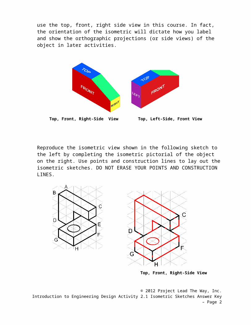
Reproduce the isometric view shown in the following sketch to the left by completing the isometric pictorial of the object on the right. Use points and construction lines to lay out the isometric sketches. DO NOT ERASE YOUR POINTS AND CONSTRUCTION LINES.
Top, Front, Right-Side View
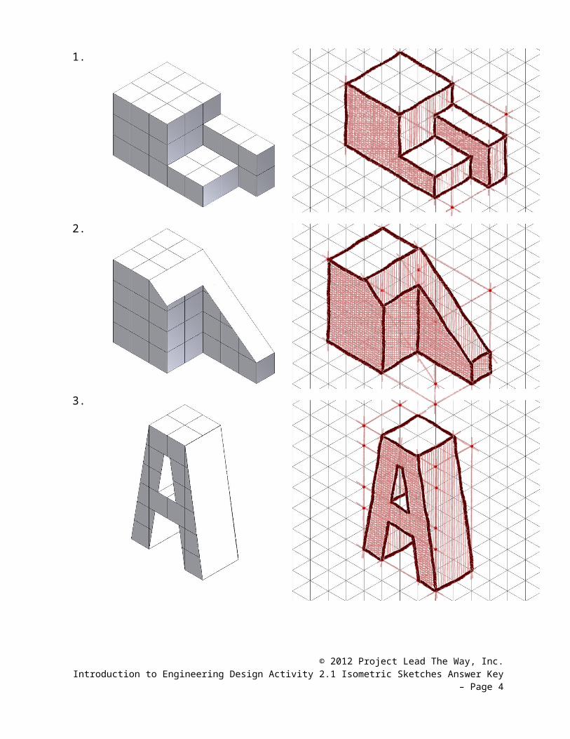
Make isometric sketches of the three objects pictured in the following diagram. Sketch the objects using the same orientation in which they are pictured. Use points and construction lines to lay out the isometric sketches. Then delineate the visible edges of each sketch with heavy object lines to make them stand out. DO NOT ERASE YOUR POINTS AND CONSTRUCTION LINES. Add tonal shading to the sketches when finished.
© 2012 Project Lead The Way, Inc.Introduction to Engineering Design Activity 2.1 Isometric Sketches Answer Key – Page 2
1.
2.
3.
© 2012 Project Lead The Way, Inc.Introduction to Engineering Design Activity 2.1 Isometric Sketches Answer Key – Page 3
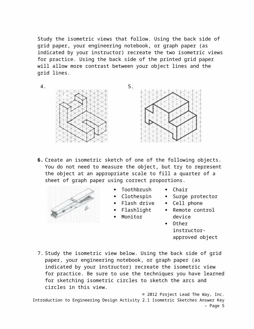
Study the isometric views that follow. Using the back side of grid paper, your engineering notebook, or graph paper (as indicated by your instructor) recreate the two isometric views for practice. Using the back side of the printed grid paper will allow more contrast between your object lines and the grid lines.
4. 5.
6. Create an isometric sketch of one of the following objects. You do not need to measure the object, but try to represent the object at an appropriate scale to fill a quarter of a sheet of graph paper using correct proportions.
Toothbrush Clothespin Flash drive Flashlight Monitor
Chair Surge protector Cell phone Remote control
device Other instructor-
approved object
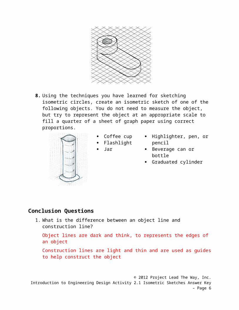
7. Study the isometric view below. Using the back side of grid paper, your engineering notebook, or graph paper (as indicated by your instructor) recreate the isometric view for practice. Be sure to use the techniques you have learned for sketching isometric circles to sketch the arcs and circles in this view.
8. Using the techniques you have learned for sketching isometric circles, create an isometric sketch of one of the following objects. You do not need to measure the
© 2012 Project Lead The Way, Inc.Introduction to Engineering Design Activity 2.1 Isometric Sketches Answer Key – Page 4
object, but try to represent the object at an appropriate scale to fill a quarter of a sheet of graph paper using correct proportions.
Coffee cup Flashlight Jar
Highlighter, pen, or pencil Beverage can or bottle Graduated cylinder
Conclusion Questions1. What is the difference between an object line and construction line?
Object lines are dark and think, to represents the edges of an object
Construction lines are light and thin and are used as guides to help construct the object
2. Why do designers use tonal shading?
To make the object look more realistic, more 3D
3. How do you decide on which view of an object should be your front view?
Recommendations for how to select the front view
a. Most natural position or use
b. Shows best shape and characteristic contours
c. Longest dimensions
d. Fewest hidden lines
e. Most stable and natural position
© 2012 Project Lead The Way, Inc.Introduction to Engineering Design Activity 2.1 Isometric Sketches Answer Key – Page 5
4. What are the pros of using isometric drawings?
Isometric drawing look the “most 3D” Isometric are the most widely used type of pictorial in industry
A. They are used as the standard type of pictorial
B. They are used in engineering software
5. What angle measurements are the most important to help draw isometric drawings?
30, 60, 120 degree angles
6. What is a pictorial drawing?
A drawing that appears to look 3d by showing three sides of an object, isometric sketches are pictorials
7. How is technical drawing similar and difference from artistic drawing (like are class)?
Technical drawing is to convey information about an object. It must be drawn a certain way, because there are rules for each drawing type. There are usually annotation.
Artistic drawing is to bring pleasure to the audience. Convey emotion
© 2012 Project Lead The Way, Inc.Introduction to Engineering Design Activity 2.1 Isometric Sketches Answer Key – Page 6