Embed Size (px)
Citation preview
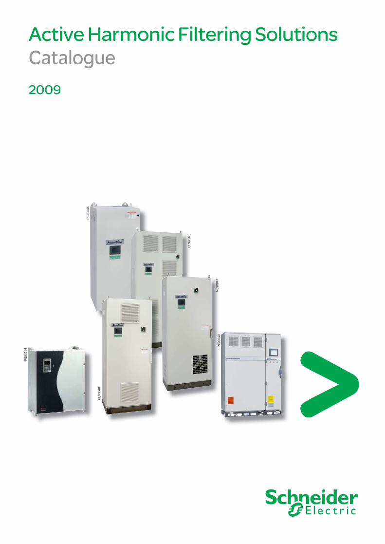
Active Harmonic Filtering Solutions Catalogue 2009
PE
9004
4
PE
9004
9
PE
9000
1
PE
9000
2
PE
9004
9
PE
9004
5
PE
9004
6
PE
9004
7
PE
9004
8

AMTED109015EN.indd - Active Harmonic Filtering Solutions
1
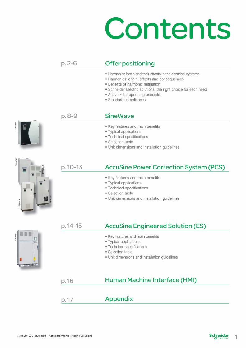
Contents
AMTED109015EN.indd - Active Harmonic Filtering Solutions
Offer positioning• Harmonics basic and their effects in the electrical systems• Harmonics: origin, effects and consequences• Benefits of harmonic mitigation• Schneider Electric solutions: the right choice for each need• Active Filter operating principle• Standard compliances
p. 2-6
Human Machine Interface (HMI) p. 16
SineWave• Key features and main benefits• Typical applications• Technical specifications• Selection table• Unit dimensions and installation guidelines
p. 8-9
PE
9004
4
AccuSine Power Correction System (PCS)• Key features and main benefits• Typical applications• Technical specifications• Selection table• Unit dimensions and installation guidelines
p. 10-13
AccuSine Engineered Solution (ES)• Key features and main benefits• Typical applications• Technical specifications• Selection table• Unit dimensions and installation guidelines
p. 14-15
PE
9004
9
Appendixp. 17
PE
9004
5
PE
9004
6
PE
9004
8
PE
9004
7

Offer positioning
Harmonics basic and their effects in the electrical systems
Harmonics are a growing concern in the management of electrical systems today.Designers are requested to pay more and more attention to energy savings and improved electricity availability. In this context, the topic of Harmonics is often discussed but there is still a need for more explanation, in order to dissipate confusion and misinterpretation.Power electronic devices have become abundant today due to their capabilities for process control and energy saving benefits. However, they also bring drawbacks to electrical distribution systems: harmonics. The presence of harmonics in electrical systems means that current and voltage are distorted and deviate from sinusoïdal waveforms.
Harmonics: origin, effects and consequences
Harmonic currents are caused by non-linear loads connected to the distribution system. A load is said to be non-linear when the current it draws does not have the same waveform as the supply voltage. The flow of harmonic currents through system impedances in turn creates voltage harmonics, which distort the supply voltage.Equipment consisting of power electronics circuits are typical non-linear loads. Such loads are increasingly frequent in all industrial, commercial, and residential installations and their percentage in overall electrical consumption is growing steadily.Examples include:• Industrial equipment (welders, induction furnaces, battery chargers, DC power supplies),• Variable Speed Drives for AC or DC motors,• Uninterruptible Power Supplies,• Office equipment (PCs, printers, servers, etc.),• Household appliances (TV sets, microwave ovens, fluorescent lighting, light dimmers).
Harmonic currents increase the r.m.s. current in the different circuits and deteriorate the supply voltage quality. They stress the electrical network and potentially damage equipment. They may disrupt normal operation of devices and increase operating costs.Symptoms of problematic harmonic levels include overheating of transformers, motors and cables, thermal tripping of protective devices, and logic faults of digital devices. In addition, the lifespan of many devices can be reduced by elevated operating temperature.
Instantaneous effects
• Harmonics can disrupt controllers used in electronic systems and can adversely affect thyristor switching due to displacement of the zero-crossing of the voltage wave• Harmonics can cause vibrations and audible noise in electrical machines (motors, transformers, reactors)• Harmonics also reduce available system capacity
2 AMTED109015EN.indd - Active Harmonic Filtering Solutions
Long-term effects
• Capacitor heating and degradation (capacitance loss)• Heating due to additional losses in transformers• Heating of busbars, cables and equipment• Thermal damage to induction motors and generators

Offer positioning
3AMTED109015EN.indd - Active Harmonic Filtering Solutions
Benefits of harmonic mitigation
Harmonic mitigation provides several benefits that could be translated into financial savings for the investor and for the user. It will contribute to improve competitiveness of companies in different ways:
• Up to 25% Capex and Opex reduction commonly achievable,• Improved business performance: downtime significantly reduced, increased equipment lifetime, up to 32% for single phase machines, up to 18% for three phase machines and up to 5% for transformers.
Reduce capital expenditures
Saving on Capex is the permanent concern of the investor. Harmonic management provides the opportunity for significant savings ; especially on the cost of equipment. Harmonic mitigation reduces the r.m.s. value of the current and so reduces the size of busbars and cables, and the rating of circuit-breakers and contactors.
Reduce operating expenses
Opex will be impacted in different ways:• Harmonic mitigation generally contributes to reduced power losses in transformers, cables, switchgear… • Harmonic mitigation allows reducing the subscribed power to the energy supplier.This saving depends on the energy supplier.In most of the cases, savings could be up to 10% of the electricity bill.
Improve electricity availability and business performance
• Increase reliability and service life.• Reduce risks of outage.• Increase productivity & quality.• Extended equipment lifetime.
PE
9000
9
PE
9000
10
PE
9005
0

Offer positioning
Reactive energy fluctuation
Equipment such as welders, induction furnaces, lifts, crushers … operate with rapid and frequent load variations. This results in rapid changes of reactive power requirements. Since the circulation of reactive power in the distribution networks is responsible for voltage drops along the lines, the consequence is the occurrence of fast and large voltage fluctuations at the user’s level. This will produce light flicker and cause disturbances of sensitive equipment.
Renewable energy generators such as wind turbines, solar panels and small hydro generators are requested by the Utilities to supply reactive energy. The objective is to provide voltage support at the point of connection and reduce the effect of a weak grid.
In all these situations, the best result is obtained with fast and continuous reactive energy compensation.
Improve Power Quality
Avoid voltage fluctuations responsible for flicker and disturbance of sensitive equipment.
Provide voltage support on weak grids
Continuous and fast compensation contributes to the efficiency of renewable energy generators connected on weak grids.
Applications
Water and wastewater treatment plants, textile mills, paper mills, pharmaceutical facilities, steel mills, package sorting facilities, oil platforms and marine vessels
WatWaterer andand wa wastestewatwaterer tretreatmatmentent pl plantantss,
Performance
• Total harmonic voltage distortionTHD(V) to be < 5%• Total Demand Distortion (TDD) to meet equipment operating environment to prevent damage to other equipment in the facility
Benefits
• Reduce harmonics to meet industry standards• Reduce harmonic effects on equipment• Increase system capacity by improving total power factor
Smelters, induction furnaces,DC drives and cranes
Fast reactive power compensation in richharmonic operating environment
• Eliminate highly fluctuatingharmonic content• Provide real-time supply of reactivepower to improve system voltage regulation
Data centers, hospitals and microelectronic manufacturers
Critical uptime requirements incorporate backup power systems with generators, UPS
• Reduce harmonics• Correct leading power factor when blade servers are used on the output of UPS
Welders, linear induction motors, windmills, X-ray and MRI machines
Ultra fast var compensation • Provide ultra fast var compensation to ensure stable voltage level for the process• Eliminate flicker • Improve diagnostic machine up time
BB
••sst•• •• tto
••hha••ppo
••••sse
••een••••
••TT••eettoin
FFFFhh
CCCCinww
UUUU
4 AMTED109015EN.indd - Active Harmonic Filtering Solutions
PE
9000
51
PE
9000
52
PE
9000
53

Offer positioning
20A 50A 120A 300A 480A 600A 3000A
690 V
480 V
400 V
4W
3W
3W
3W
3W 3wire4W 4wire
5AMTED109015EN.indd - Active Harmonic Filtering Solutions
Schneider Electric solutions: the right choice for each need
Schneider Electric is specialised in harmonic mitigation objectives and is therefore offering a broad range of solutions for every demand.We propose solutions which maximize the savings when balanced with the cost of the harmonic mitigation equipment to get a reasonable Return On Investment (ROI). Schneider Electric can propose 3 different ranges of active filters: SineWave, AccuSine Power Correction System (PCS), and AccuSine Engineered Solution (ES), which cover a large extent of customer needs. Their main characteristics are summarized below.
SineWave
• Three or four wire connection (3 phase or 3 phase + Neutral).• 400V supply, other voltages possible with transformers.• Units from 20A to 120A, with possible parallel operation up to 480 A.• Cancellation up to the 25th harmonic.• Neutral harmonic correction at 3 times unit rating.
AccuSine Power Correction System (PCS)
• Three wire connection.• From 230 V to 480 V supply (higher voltage level possible with transformer).• Filtering at network level, units from 50 A to 300 A, with possible parallel operation up to 3000 A.• Cancellation up to the 50th harmonic.
AccuSine Engineered Solution (ES)
• Three wire connection.• 400V supply (higher voltage level possible with transformer).• Filtering at network level up to 3000 A.• Cancellation up to the 25th harmonic.• Possible correction of individual harmonics.• Advanced Human Machine Interface (HMI).
Buildings
Industry
Engineery
Products:SineWave - p. 8
AccuSine PCS - p. 10
AccuSine ES - p. 14
by paralleling of units
SineWave
AccuSine PCS AccuSine ES
AccuSine ES
AccuSine PCS
AccuSine PCS
DE
9005
1

Offer positioning
Active Filter operating principle
Active harmonic filters today are designed with two types of control schemes. Discrete logic uses Fast Fourier Transforms (FFT), or other digital means, to calculate the amplitudes and phase angle of each harmonic order. The power devices are directed to produce a current of equal amplitude but opposite phase angle for specific harmonic orders. This limits the response to specific harmonic orders and may require up to two or more cycles (>33 milliseconds) before responding. SineWave and AccuSine ES employ this logic.
The other control scheme (as used by AccuSine PCS) is called Full Spectrum Cancellation. This control scheme doesn’t perform FFT. The control algorithms are analog. The controller acquires the current sample from the current transformer, removes the fundamental frequency component and starts injecting the correction within several hundred microseconds. In this manner, all non-fundamental “noise” is removed for the electrical source. This “noise” may contain non-integer frequencies, also known as inter-harmonics.
Sinewave and AccuSine active filters are also designed to inject reactive current at fundamental frequency to provide power factor correction and, in some cases, compensate for rapid load fluctuations to provide voltage support.
00,51
1,52
-0,5-1
-1,5-2
00,51
1,52
-0,5-1
-1,5-2
+ =
= =
00,51
1,52
-0,5-1
-1,5-2
00,51
1,52
-0,5-1
-1,5-2
00,51
1,52
-0,5-1
-1,5-2
00,51
1,52
-0,5-1
-1,5-2
Harmonicgenerators
ActiveFilter
Result
Harmonicgenerators
ActiveFilter
MV
M
Harmonics
6 AMTED109015EN.indd - Active Harmonic Filtering Solutions
DE
9005
2

Standard compliances
By using Schneider Electric active filters, it is possible to put any installation in compliance with the most relevant standards and regulations:• IEEE 519: recommended practices and requirements for harmonic control in Electrical Power Systems.• IEC 61000.3.6: assessment of emission limits for the connection of distorting installations to MV, HV and EHV power systems.• ER G5/4: planning levels for harmonic voltage distortion and the connection of non-linear equipment to transmission systems and distribution networks in the United Kingdom.
7AMTED109015EN.indd - Active Harmonic Filtering Solutions
Offer positioning
Before After
DE
9004
8

SineWave
Key features and main benefits
• Correction capacity per unit: 20, 30, 45, 60, 90, 120 Amperes.• Voltage: base design 400 VAC 3-phase supply, other voltages with transformer.• Harmonic compensation: H3 to H25, global or selective.• Reactive compensation: power factor correction, cos φ to near unity, selectable set point.• Electrical systems: 3-wire or 4-wire.• Neutral current correction: 3 times unit rating.• Product standards: CE Certified.• Parallel capability: up to 4 like units to 480 Amperes.• Enclosure type: IP20, wall mounted.• Communication: 3 dry (voltage free) contacts to monitor status from remote location; Optional via RS422/485 link for J-Bus and Modbus.• Functionality: harmonic mitigation or power factor correction, separately or combined.• Human Machine Interface: graphic display, seven languages.
PE
9004
4 The Schneider Electric solution for harmonic fi ltering in buildings.
Typical applications
• Data center & IT room.• Offices and buildings.• UPS systems.• Fluorescent and HID lighting• HVAC.• Computer centers.• Casinos.• Power supplies for silicon production.
Performance capability
• Stepless automatic adaption to load changes.• Suitable for all types and mixes of nonlinear loads.• Fast response at < 3 cycles.• Assist in compliance to any worldwide harmonic standards: IEEE 519, G5/4-1, GBT 14549, IEC-61000-3.• THDi reduction to approximately 1/10 of network THDi.• Corrects power factor, cos φ, for IT servers to insure proper operation of UPS.• Compatible with any type of neutral system.• Automatic adaption for unbalanced phase loading.
Easy to Control
• Three LED indicators for run, stop, and current limit.• Very user friendly graphic terminal.• Choice of seven languages.• Parameters and notifications clearly displayed.• Graphic display of THDu, THDi.• Remote run/stop via RS422/485 link via Modbus or J-Bus (Option).• Remote monitoring of parameters and notifications via RS422/485 link via Modbus or J-Bus (Option).
8 AMTED109015EN.indd - Active Harmonic Filtering Solutions

SineWave
9AMTED109015EN.indd - Active Harmonic Filtering Solutions
Technical specifications
SW20 SW30 SW45 SW60 SW90 SW120
Compensation capacity per phase 20 A rms 30 A rms 45 A rms 60 A rms 90 A rms 120 A rmsCompensation capacity in the neutral(1) 60 A rms 90 A rms 135 A rms 180 A rms 270 A rms 360 A rms
SW S SW
System input
Nominal voltage (2) 400 V -20% +15%Nominal frequency 50 Hz, 60 Hz, +/- 8%Number of phases 3 phases with or without neutral Current transformers range from 300/1 to 4000/1
Environmental conditions
Operating temperature 0 to 40°C continuousRelative humidity 0-95 % non condensingOperating altitude < 1000 m
Reference technical standards
Construction and safety EN 60950-1Design IEC 146Protection (enclosure) IP 20 conforming to IEC 529
EMC
Conducted and radiated emission EN 55011 level AImmunity to electrostatic discharge IEC 61000-4-2 level 3Immunity to electromagnetic fields IEC 61000-4-3 level 3Immunity to impulse waves IEC 61000-4-4 and IEC 61000-4-5 level 4
PE
9004
4
Technical characteristics
Compensated harmonic currents H3 to 25, full equalization or individual equalizationHarmonic attenuation rate THDI load /THDI system less than 10, at the nominal rating of the equalizerPower Factor Correction lagging or leading, up to 1.0Response time < 40 msOverload Limitation of the nominal current, possibility of continuous operation with current limitationInrush Current < 2 x the nominal peak currentCommunication Capability Jbus/Modbus card (optional) Heat losses 1000 W 1300 W 2100 W 2600 W 4200 W 5200 WAcoustic noise (ISO 3746) < 55 dBA < 60 dBA < 65 dBA Color RAL 9002
< 4 52
< 5RA
10
(1) Maximum capacity with PC-type data processing load and with three-phase balanced supply.(2) Other voltages - 208 V, 220 V, 480 V - available on request.
Unit dimensions and installation guidelines
weight: 65 kgSW 20, SW 30
weight: 110 kgSW 45, SW 60
weight: 220 kgSW 90, SW 120
680
mm
780
mm
780
mm
540 mm580 mm 580 mm
280 mm 325 mm 325 mmmmmm mm mmmm
315
mm
780
mm
780
mm
540 mm580 mm 580 mm
325 325mmm mm mmm
DE
9005
3

AccuSine PCSP
E90
048
PE
9004
5
PE
9004
6P
E90
046
PE
9004
7
The Schneider Electric solution for active harmonic fi ltering in industrial installations.
Key features and main benefits
• Correction capacity per unit: 50, 100, 300 Amperes.• Voltage: base design 208 - 480 VAC 3-phase supply, other voltages with transformer.• Harmonic compensation: H2 to H50, full spectrum cancellation; includes interharmonics.• Reactive compensation: power factor correction, cos φ to near unity, selectable set point.• Electrical systems: 3-wire or 4-wire.• Neutral current correction: None.• Product standards: CE Certified, UL, cUL, CSA, ABS, C-Tick.• Parallel capability: up to 10 units of any capcity.• Enclosure type: NEMA 1, NEMA 12, IP30, IP54.• Communication: 4 dry (voltage free) contacts to monitor status from remote location; Modbus TCP/IP or Ethernet IP.• Functionality: harmonic mitigation or power factor correction, separately or combined.• Human Machine Interface: graphic display with touch screen control.
Performance capability
• Stepless automatic adaption to load changes.• Suitable for all types and mixes of nonlinear loads.• Ultra fast response at < 1 cycle.• Provides compliance to any worldwide harmonic standard: IEEE 519, G5/4-1, GBT 14549, IEC-61000-3.• THDi reduction to approximately 1/10 of network THDi.• Rapid injection of reactive current within 100 µSec (also known as VAR compensation or flicker control).• Automatic adaption for unbalanced phase loading.
Easy to Control
• One LED indicator for power on.• Very user friendly graphic terminal.• Easy to read 96 mm QVGA screen.• Parameters and notifications clearly displayed.• Graphic display of all current trends.• Remote monitoring and run/stop control via Modbus TCP/IP over ethernet.• Total remote control, including parameter setup, and monitoring via Ethernet IP (webserver).
VAR compensation applications
• Arc welders.• Rock crushers.• Vehicle shredders.• Arc furnaces.• Roller coasters.
Typical applications
• Oil and gas platforms.• Port cranes.• Steel.• Water/Wastewater.• HVAC.• Automotive.• Process plants.• Pulp and paper.• Wind and solar farms. • Lifts (ski or building)• Marine vessels…
10 AMTED109015EN.indd - Active Harmonic Filtering Solutions

AccuSine PCS
11AMTED109015EN.indd - Active Harmonic Filtering Solutions
System input
Nominal voltage 208-480V +/- 10 % auto-sensing ; other voltages with transformersNominal frequency 50/60 Hz +/- 3 % auto-sensingNumber of phases 3P/3W, 3P/4WPower Electronics IGBTTopology Analog/digital interfaceOperation with Single Phase Loads YesCurrent transformers (CT) 1,000/5, 3,000/5, 5,000/5 (400Hz)Number of CTs Required 2 or 3
Environmental conditions
Operating temperature 0° C to 40° C continuous Relative humidity 0-95 % non-condensingSeismic Qualification IBC and ASCE7Operating altitude < 1,000 m, (derating factors apply for higher altitudes @10% per 1,000 m)
Reference technical standards
Design Optional: CE EMC Certification IEC/EN 60439-1, EN 61000-6-4 Class A, EN 61000-6-2Protection (enclosure) NEMA 1, NEMA 12, IP30, IP54
Technical characteristics
Normal spectrum of compensation 2nd to 50th harmonic full spectrumAttenuation ratio >10:1Parallel multiple units Yes, up to 10 per set of CTs (any rating combinations)CT Location Either source or load sensingPower factor correction Yes, leading or lagging injection to target power factorResponse time 100 microseconds for step load changes, 1 cycle full responseOverload Limited to nominal output, continuous operationDynamic Current Injection Up to 2.25 times rated currentDisplay High quality 3.8" QVGA screenLanguages EnglishOperators Magelis XBT graphic touch screen terminalDisplay Parameters • AC line voltage, DC bus voltage, load power factor unit output power factor • Load harmonic current, load reactive current, output harmonic current, corrected load current • Various fault codes, set up parameter points start, stop control screenCommunication Capability Modbus, Modbus TCP/IP, EthernetHeat losses N1 unit: 1,800 W for 50 A, 3,000 W for 100 A, 9,000 W for 300 A N12, IP units: 2,150 W for 50 A, 3,700 W for 100 A, 10,000 W for 300 A Noise level (ISO 3746) < 80 db at one meter from unit surfaceColor NEMA 1 Quartz Gray, all others RAL7035
PE
9004
5
PE
9004
6
PE
9004
8
PE
9004
7
Technical specifications
Standard RMS output current ratings 50A, 100A, 300ANeutral current compensation No

Rated current Max. Reactive Catalog Number Enclosure Information Frame Weighte
A(rms) Power (kvar) 208V 400V 480V Rating Style / cable entry Figure # Lbs(kg)
50 18 34.6 41.6 PCS050D5N15S NEMA 1 Wall Mount/bottoma 1 250 (114) PCS050D5N16S PCS050D5N125SCd NEMA 12 Floor Standingc/ 4 661 (300) PCS050D5N126SDd top or bottom PCS050D5CE305SCbd IP30 (CE certified) PCS050D5CE545SCbd IP54 (CE certified) PCS050D5IP305SCd IP30 PCS050D5IP545SCd IP54100 36 69.2 83.1 PCS100D5N15S NEMA 1 Wall Mount/bottoma 2 350 (159) PCS100D5N16S PCS100D5N125SCd NEMA 12 Floor Standingc/ 5 771 (350) PCS100D5N126SDd top or bottom PCS100D5CE305SCbd IP30 (CE certified) PCS100D5CE545SCbd IP54 (CE certified) PCS100D5IP305SCd IP30 PCS100D5IP545SCd IP54300 108 207.8 249.4 PCS300D5N15S NEMA 1 Floor Standingc/top 3 775 (352) PCS300D5N16S PCS300D5N125SCd NEMA 12 Floor Standing 6 1,212 (550) PCS300D5N126SDd
PCS300D5CE305SCbd IP30 (CE certified) PCS300D5CE545SCbd IP54 (CE certified) PCS300D5IP305SCd IP30 PCS300D5IP545SCd IP54
AccuSine PCS
Ampacity Catalog Number Dimensions (in.) Weight Accuracy class Burden Secondary A (ID) D (OD) (lbs.) capacity (A) current (A) 1,000 CT1000SC 4.0 6.5 3.50 1 10 5 3,000 CT3000SC 6.0 8.5 4.25 1 45 5 5,000 CTFCL500058 8.0 10.5 5.50 1 45 5
C
W(l
DA
A
Sc
s Bc
4 3 11 5C
Round split-core CT selection table
5 5
CT1000SC 4.0 6.5 3.50 1 10 CT3000SC 6.0 8.5 4.25 1 45
46
34
14
11
1,000 3,000
55
CC
,5,000 5 CTFCL500058 8.0 10.5 5.50 1 45 8 5 41 5C5 CT3000SC 6.0 8.5 4.25 1 45 6 4 413,000 5C
,
Three CTs required for networks with single phase loads. Two CTs required for three phase loads. For installations requiring parallel connection of multiple AccuSine units, special considerations are required, and additional CT may be needed. Contact Schneider Electric for details.
PE
9004
5
PE
9004
6
PE
9004
8
PE
9004
7
Selection table
Fra
Fig
1
En
Ra
Ca
PC
MaPo20
18
We
Lb
AccuSine PCS selection table
CS050D5N126SDd PC
PCS050D5IP305SCd PC 30
0 (159)all Mount/bottoma 2 2 EMA 1
100 36 69.2 83.1 PCS100D5N15S PC 36
CS050 5 5SPCS050D5N16S
CPC
1 (300)oor Standingc/ 4 4 EMA 12 PCS050D5N125SCd PCPCS050D5N16SPC
54PCS050D5IP545SCdPC 54PCS050D5IP545SC PC
1 (350)oor Standingc/ 5 5 EMA 12 PCS100D5N125SCdPC
PCS300D5N16SPC,
25
35
66
77top
top
Wa
Wa
Flo
Flo
NE
IP3
NE
NE
IP5IP5
NE
5 (352)oor Standingc/top 3 EMA 1 77Flo
300 108 207.8 249.4 PCS300D5N15S PC 10 CS300 5 5SC NE
30 (CE certified)PCS300D5CE305SCbd PC IP3
212 (550)
oor Standing
6 EMA 12 PCS300D5N125SCdPC
PCS300D5N16S PC 1,2Flo
NE
PCS300D5CE545SCbdPC 54 (CE certified)IP5( ed)
54CS300D5IP545SCd PC IP5CS300D5IP305SCdPC 30IP3
54 (CE certified)CS300D5CE545SC PC IP530CS300D5IP305SC PC IP3
PCS050D5CE545SCbdPC( )
54 (CE certified)54 (CE certified)PCS050D5CE545SCPC IP5IP530 (CE certified)CS050D5CE305SCbd PC
CS050D5N126SDPC toIP30 ( )
PCS100D5N16SPCPCS100D5N15S PCPCS100D5N16S PC
N
CS100D5N126SDd PCCS100D5N125SC PC N
PCS100D5IP305SCd PC 30IP3
( )54 (CE certified)PCS100D5CE545SCbdPC IP5 (C d)30 (CE certified)CS100D5CE305SCbdPC
toIP3
CS100D5N126SDPC30 (CE certified)CS100D5CE305SCPC IP3
54PCS100D5IP545SCdPC IP554PCS100D5IP545SC PC IP530CS 00 5 305SCC 3
PCS300D5N126SDdPCPCS300D5N126SDPCPCS300D5N125SCPC N
a: Floor stand can be ordered with part number – FSPCS100N1b: CE certifi ed units meet EMC Directive 89/336 EECc: Floor-standing units include a door-interlocked main disconnectd: C = 380–415 V fan, D = 480 V fane: Weight information is subject to change without notice
12 AMTED109015EN.indd - Active Harmonic Filtering Solutions

Frame Size Exterior dimensionsFigure Height Width Depth in. mm in. mm in. mm
1 48.0 1,219 20.7 525 18.5 4692 64.9 1,648 20.7 525 18.5 4693 75.3 1,913 31.5 801 19.6 4974/5 75.0 1,905 31.5 801 23.8 6056 90.7 2,303 39.4 1,000 31.7 805
AccuSine PCS
13AMTED109015EN.indd - Active Harmonic Filtering Solutions
m
5881
5
Wi
2333
2
m
1112
16779
4
EHin
321
11
m
Unit dimensions and installation guidelines
864
44
Frame size 1
Frame size 2
Frame size 3
Frame size 4 & 5
Frame size 6
Front view Side view
Front view Side view
Front view Side view Front view Side view
Front view Side view
PE
9000
5P
E90
004
PE
9000
6
PE
9000
8P
E90
007
PE
9000
4
PE
9004
5
12346
F
PE
9000
41
654
32
For detailed installation instructions, please refer to installation bulletin 5820IB0802.Chassis unit information is available upon request.
iD
PE90067
PE
9004
6
PE
9004
8
PE
9004
7
PE9
0066

AccuSine ESP
E90
009
PE
9005
6
PE
9005
7
Dual IGBT bridge
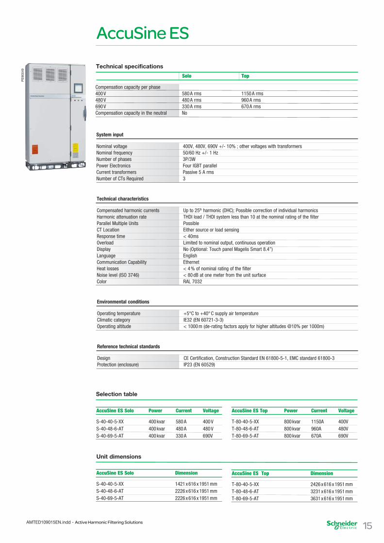
The Schneider Electric solution for active harmonic fi ltering for specifi c and high performance solutions.Key features and main benefits• Correction capacity up to 1150 A at 400 V. • Voltage: base design 400 VAC 3-phase supply, standard packages at 480 and 690 VAC, other voltages with transformer.• Harmonic compensation: H2 to H25, global or selective via DHC.• Reactive compensation: power factor correction, cos φ to near unity, selectable set point.• Electrical systems: 3-wire.• Neutral current correction: None.• Product standards: CE Certified.• Parallel capability: up to 10 units of any capacity.• Enclosure type: IP23.• Communication: 4 dry (voltage free) contacts to monitor status from remote location; Ethernet IP.• Functionality: harmonic mitigation or power factor correction, separately or combined.• Human Machine Interface: graphic display with touch screen control.
Performance capability• Stepless automatic adaption to load changes.• Suitable for all types and mixes of nonlinear loads.• High dynamic response through ultra fast logic sampling every 12.5 µsec.• Ultra fast response at < 1 cycle.• Provides compliance to any worldwide harmonic standard: IEEE 519, G5/4-1, GBT 14549, IEC-61000-3.• THDi reduction to approximately 1/10 of network THDi.• Rapid injection of reactive current within 200 µSec (also known as VAR compensation or flicker control).• Automatic adaption for unbalanced phase loading.• Load balancing to protect the electrical network.
Easy to Control• Two LED indicators for power on and status (color changes included).• Very user friendly graphic terminal.• Easy to read 213mm SVGA screen.• Parameters and notifications clearly displayed.• Graphic display of all current trends.• Remote monitoring and run/stop control via ethernet.• Total remote control, including parameter setup, and monitoring via Ethernet IP (webserver).• Easy setup using PC.
VAR compensation applications• Arc welders.• Rock crushers.• Vehicle shredders.• Arc furnaces.• Roller coasters.
Typical applications
• Oil and gas platforms.• Port cranes.• Steel.• Water/Wastewater.• HVAC.• Automotive.• Process plants.• Pulp and paper.• Wind and solar farms. • Lifts (ski or building)• Marine vessels…
14 AMTED109015EN.indd - Active Harmonic Filtering Solutions
AccuSine ES
15AMTED109015EN.indd - Active Harmonic Filtering Solutions
System input
Nominal voltage 400V, 480V, 690V +/- 10% ; other voltages with transformersNominal frequency 50/60 Hz +/- 1 Hz Number of phases 3P/3WPower Electronics Four IGBT parallelCurrent transformers Passive 5 A rmsNumber of CTs Required 3
Environmental conditions
Operating temperature +5°C to +40° C supply air temperature Climatic category IE32 (EN 60721-3-3)Operating altitude < 1000 m (de-rating factors apply for higher altitudes @10% per 1000m)
Reference technical standards
Design CE Certification, Construction Standard EN 61800-5-1, EMC standard 61800-3Protection (enclosure) IP23 (EN 60529)
Technical characteristics
Compensated harmonic currents Up to 25th harmonic (DHC); Possible correction of individual harmonicsHarmonic attenuation rate THDI load / THDI system less than 10 at the nominal rating of the filterParallel Multiple Units PossibleCT Location Either source or load sensingResponse time < 40msOverload Limited to nominal output, continuous operationDisplay No (Optional: Touch panel Magelis Smart 8.4”)Language EnglishCommunication Capability EthernetHeat losses < 4 % of nominal rating of the filterNoise level (ISO 3746) < 80 dB at one meter from the unit surfaceColor RAL 7032
PE
9004
9
Technical specifications
Compensation capacity per phase 400 V 580 A rms 1150 A rms480 V 480 A rms 960 A rms690 V 330 A rms 670 A rmsCompensation capacity in the neutral No
Solo Top
Selection table
AccuSine ES Solo Power Current Voltage
S-40-40-5-XX 400 kvar 580 A 400 VS-40-48-6-AT 400 kvar 480 A 480 VS-40-69-5-AT 400 kvar 330 A 690V
AccuSine ES Top Power Current Voltage
T-80-40-5-XX 800 kvar 1150A 400VT-80-48-6-AT 800 kvar 960A 480VT-80-69-5-AT 800 kvar 670A 690V
AccuSine ES Solo Dimension
S-40-40-5-XX 1421 x 616 x 1951 mmS-40-48-6-AT 2226 x 616 x 1951 mmS-40-69-5-AT 2226 x 616 x 1951 mm
Unit dimensions
AccuSine ES Top Dimension
T-80-40-5-XX 2426 x 616 x 1951 mmT-80-48-6-AT 3231 x 616 x 1951 mmT-80-69-5-AT 3631 x 616 x 1951 mm

Human Machine Interface (HMI)
Keypad
Direct control of the active filters is possible by using the RUN/STOP commands on a keypad.
Display
A graphical Display is used for different functions:• Access and set up of operating parameters.• Measurement data.• Operation status (warnings, fault messages).Menus are accessible for easy navigation.
Configuration parameters
List of selectable parameters:• User language,• 3- or 4-wire configuration,• Harmonics or reactive energy compensation (separately or in combination),• Current transformer ratio,• Power factor target,• Number of units in parallel,• Communication parameters.
Measurements
A complete set of measurement data is accessible:• Line-to-line r.m.s. voltages.• Total r.m.s load currents (on three phases).• Active filter output r.m.s currents (on three phases).• Harmonic r.m.s load and line currents.• Voltage and current distortions (THDu and THDi).• Reactive r.m.s load current.• Active filter reactive r.m.s output current.• Heatsink temperature (in deg. C).
Alarms and Fault display
Detailed alarms and fault messages are displayed for easy trouble shooting:• Supply voltage or frequency outside of normal operating range.• Current limitation.• Overtemperature.• Controller fault.• Communication fault.
The three different ranges of active fi lters offered by Schneider Electric provide a Human Machine Interface (HMI) including a Graphical User Interface. Direct control, programming and monitoring are possible without using a PC.
16 AMTED109015EN.indd - Active Harmonic Filtering Solutions
PE
9000
58
Appendix
17AMTED109015EN.indd - Active Harmonic Filtering Solutions
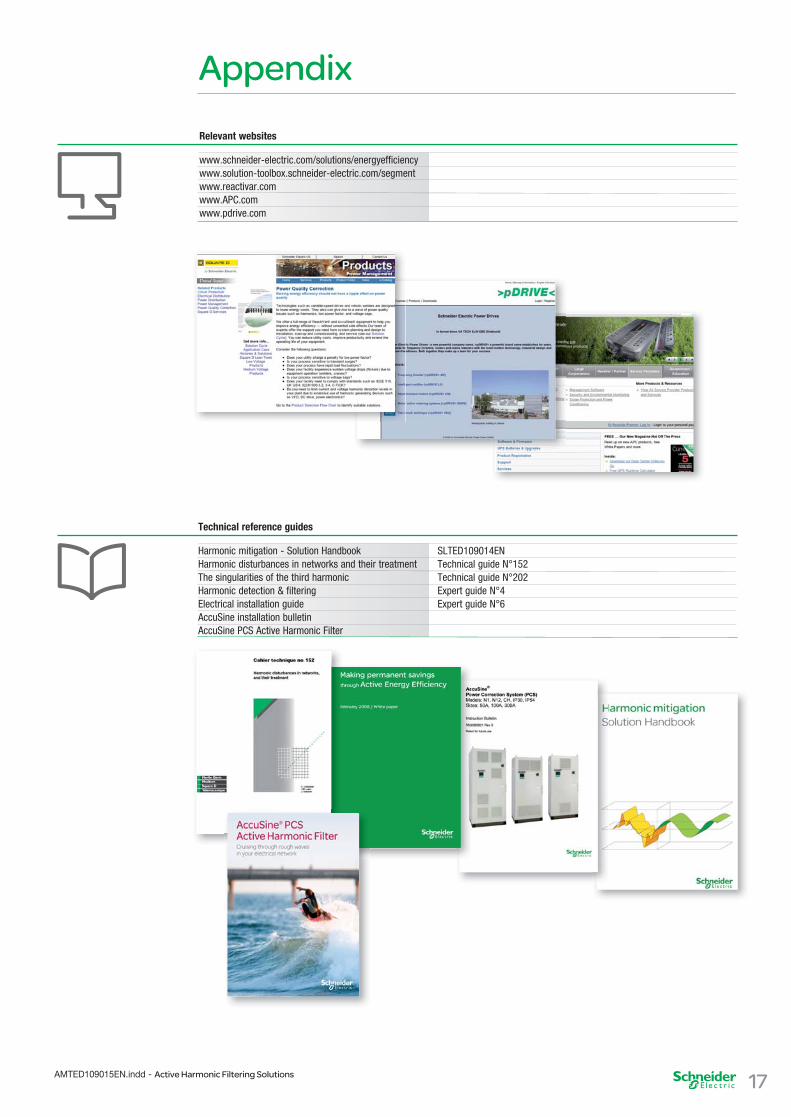
Relevant websites
www.schneider-electric.com/solutions/energyefficiency www.solution-toolbox.schneider-electric.com/segment www.reactivar.com www.APC.comwww.pdrive.com
Technical reference guides
Harmonic mitigation - Solution Handbook SLTED109014EN Harmonic disturbances in networks and their treatment Technical guide N°152 The singularities of the third harmonic Technical guide N°202 Harmonic detection & filtering Expert guide N°4 Electrical installation guide Expert guide N°6 AccuSine installation bulletinAccuSine PCS Active Harmonic Filter

Schneider Electric Industries SASHead Office35 rue Joseph MonierCS 3032392506 Rueil-Malmaisonwww.schneider-electric.com
As standards, specifications and designs change from time to time, please ask for confirmation of the information given in this publication.
Publishing: SYNTHESE ECA, Schneider Electric.
08/2009
AR
T837
595
© S
chne
ider
Ele
ctric
Ind
ustr
ies
SA
S -
All
right
s re
serv
ed
Active Harmonic Filtering Solutions
AMTED109015EN


![HARMONIC fILTERING - NHP Electrical Quality/NHP-Schaffner... · [2] HARMONIC fILTERING Schaffner, established in 1962 and with over 1,700 employees worldwide, is the international](https://img.dokumen.tips/doc/110x75/5a70930d7f8b9aac538c0ad0/harmonic-filtering-nhp-electricalwwwnhpcomaufileseditoruploadfilepower.jpg)