Embed Size (px)
Citation preview
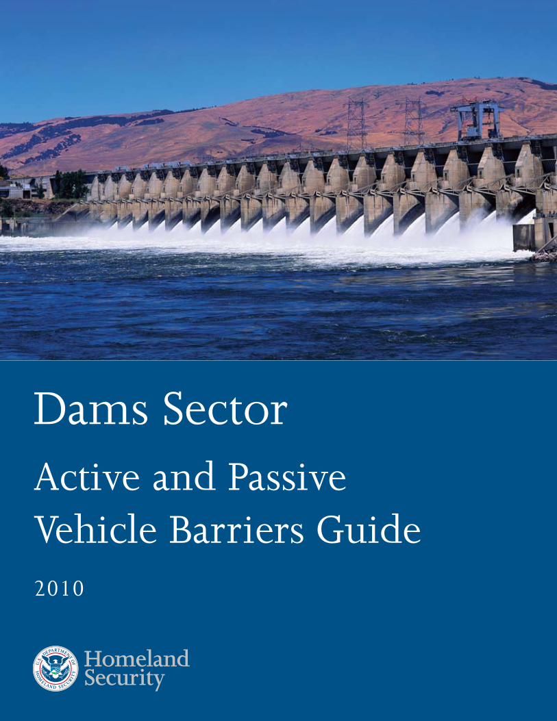
Dams Sector Active and Passive Vehicle Barriers Guide 2010
Dams Sector Active and Passive Vehicle Barriers Guide
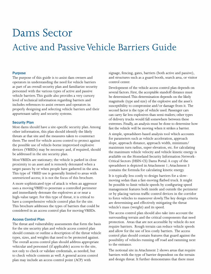
Purpose The purpose of this guide is to assist dam owners and operators in understanding the need for vehicle barriers as part of an overall security plan and familiarize security personnel with the various types of active and passive vehicle barriers.This guide also provides a very cursory level of technical information regarding barriers and includes references to assist owners and operators in properly designing and selecting vehicle barriers and their appurtenant safety and security systems.
Security Plan Most dams should have a site-specific security plan. Among other information, this plan should identify the likely threats at that site and the measures taken to counteract them.The need for vehicle access control to protect against the possible use of vehicle-borne improvised explosive devices (VBIEDs) may be necessary and, if required, should be addressed in the site security plan.
Most VBIEDs are stationary; the vehicle is parked in close proximity to an asset and is remotely detonated when a target passes by or when people have gathered in the area. This type of VBIED use is generally limited to areas with unrestricted access; it is not the focus of this brochure.
A more sophisticated type of attack is when an aggressor uses a moving VBIED to penetrate a controlled perimeter and immediately detonate the explosives at or near a high-value target. For this type of threat, it is critical to have a comprehensive vehicle control plan for the site. This brochure addresses the types of barriers that could be considered in an access control plan for moving VBIEDs.
Access Control Plan The threat and vulnerability assessments that form the basis for the site security plan and vehicle access control plan should contain or outline a description of the threat vehicle types, sizes, and weights that need to be protected against. The overall access control plan should address appropriate vehicular and personnel (if applicable) access to the site, not only to check or validate credentials, as needed, but to check vehicle contents as well. A general access control plan may include an access control point (ACP) with
signage, fencing, gates, barriers (both active and passive), and structures such as a guard booth, search area, or visitor control center.
Development of the vehicle access control plan depends on several factors. First, the acceptable standoff distance must be determined.This determination depends on the likely magnitude (type and size) of the explosive and the asset’s susceptibility to compromise and/or damage from it. The second factor is the type of vehicle used. Passenger cars can carry far less explosives than semi-trailers; other types of delivery trucks would fall somewhere between these extremes. Finally, an analysis must be done to determine how fast the vehicle will be moving when it strikes a barrier.
A simple, spreadsheet-based analysis tool which accounts for parameters such as vehicle acceleration, approach slope, approach distance, approach width, minimum/ maximum turn radius, super elevation, etc. for calculating the maximum vehicle velocity and vehicle kinetic energy is available on the Homeland Security Information Network-Critical Sectors (HSIN-CS) Dams Portal. A copy of the spreadsheet is depicted in Attachment 1; Attachment 3 contains the formula for calculating kinetic energy.
It is typically less costly to design barriers for a slow-moving sedan than a fast-moving flatbed truck. It might be possible to limit vehicle speeds by configuring speed management features both inside and outside the perimeter or by placing various traffic control devices in the corridor to force vehicles to maneuver slowly.The key design criteria are determining and effectively mitigating the threat vehicle’s mass (weight) and its speed.
The access control plan should also take into account the surrounding terrain and the critical components that need protection. Areas that are not accessible by vehicle do not require barriers. Rough terrain can reduce vehicle speeds and allow for the use of less costly barriers. The access control plan should contain features that guard against the possibility of vehicles running off road and ramming next to the entrance.
The notional site in Attachment 2 shows areas that require barriers with the type of barrier dependent on the terrain and design threat. It further demonstrates that there must
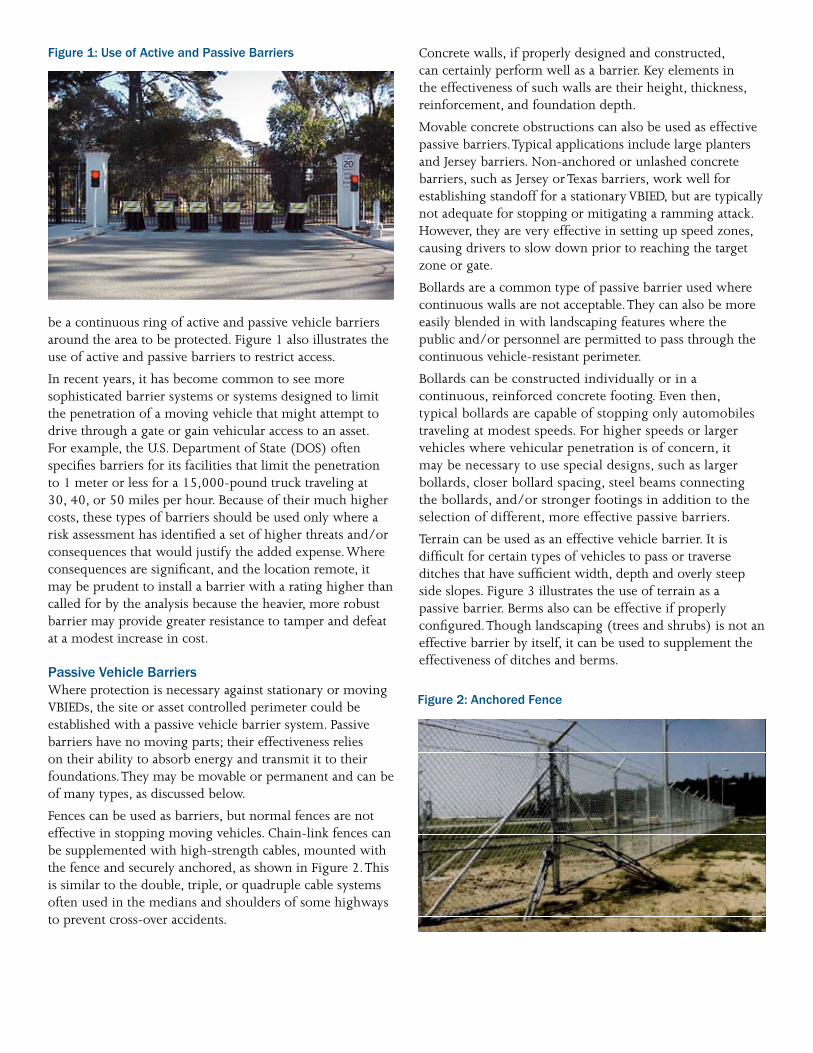
Figure 1: Use of Active and Passive Barriers
be a continuous ring of active and passive vehicle barriers around the area to be protected. Figure 1 also illustrates the use of active and passive barriers to restrict access.
In recent years, it has become common to see more sophisticated barrier systems or systems designed to limit the penetration of a moving vehicle that might attempt to drive through a gate or gain vehicular access to an asset. For example, the U.S. Department of State (DOS) often specifies barriers for its facilities that limit the penetration to 1 meter or less for a 15,000-pound truck traveling at 30, 40, or 50 miles per hour. Because of their much higher costs, these types of barriers should be used only where a risk assessment has identified a set of higher threats and/or consequences that would justify the added expense.Where consequences are significant, and the location remote, it may be prudent to install a barrier with a rating higher than called for by the analysis because the heavier, more robust barrier may provide greater resistance to tamper and defeat at a modest increase in cost.
Passive Vehicle Barriers Where protection is necessary against stationary or moving VBIEDs, the site or asset controlled perimeter could be established with a passive vehicle barrier system. Passive barriers have no moving parts; their effectiveness relies on their ability to absorb energy and transmit it to their foundations.They may be movable or permanent and can be of many types, as discussed below.
Fences can be used as barriers, but normal fences are not effective in stopping moving vehicles. Chain-link fences can be supplemented with high-strength cables, mounted with the fence and securely anchored, as shown in Figure 2.This is similar to the double, triple, or quadruple cable systems often used in the medians and shoulders of some highways to prevent cross-over accidents.
Concrete walls, if properly designed and constructed, can certainly perform well as a barrier. Key elements in the effectiveness of such walls are their height, thickness, reinforcement, and foundation depth.
Movable concrete obstructions can also be used as effective passive barriers.Typical applications include large planters and Jersey barriers. Non-anchored or unlashed concrete barriers, such as Jersey or Texas barriers, work well for establishing standoff for a stationary VBIED, but are typically not adequate for stopping or mitigating a ramming attack. However, they are very effective in setting up speed zones, causing drivers to slow down prior to reaching the target zone or gate.
Bollards are a common type of passive barrier used where continuous walls are not acceptable.They can also be more easily blended in with landscaping features where the public and/or personnel are permitted to pass through the continuous vehicle-resistant perimeter.
Bollards can be constructed individually or in a continuous, reinforced concrete footing. Even then, typical bollards are capable of stopping only automobiles traveling at modest speeds. For higher speeds or larger vehicles where vehicular penetration is of concern, it may be necessary to use special designs, such as larger bollards, closer bollard spacing, steel beams connecting the bollards, and/or stronger footings in addition to the selection of different, more effective passive barriers.
Terrain can be used as an effective vehicle barrier. It is difficult for certain types of vehicles to pass or traverse ditches that have sufficient width, depth and overly steep side slopes. Figure 3 illustrates the use of terrain as a passive barrier. Berms also can be effective if properly configured.Though landscaping (trees and shrubs) is not an effective barrier by itself, it can be used to supplement the effectiveness of ditches and berms.
Figure 2: Anchored Fence

SPOIL
SPOIL
REVETTED
PROTECTED AREA
PROTECTED AREA
6’ - 7’ ½ TYP.
7’ ½ 12’ - 15’
4’
3’
5’
TRAPEZOIDAL DITCH
TRIANGULAR DITCH
Figure 3: Terrain as a Passive Barrier
Active Vehicle Barriers Vehicle access control points or entry control points where credentials and/or vehicle contents are checked might require installation of an active vehicle barrier (AVB) at the end of the access corridor.The appropriate type of barrier depends on a number of factors, as listed below.
• If the entry is unstaffed all or part of the time, is there a need for a moveable gate that can act as a pedestrian barrier when closed?
• When entry is unstaffed will the barrier resist/prevent unauthorized operation or tampering?
• When the entry is unstaffed, what can be done to provide supervision or monitoring of the barrier (tamper and/or intrusion sensors, video assessment)?
• When the entry is staffed, will the barrier normally be open or closed? If the barrier is normally open, is there a need for a back-up barrier that can be closed quickly if a vehicle attempts to force its way past the entry control point?
• What is the design speed and weight of the vehicle that must be stopped?
• How quickly must the barrier open or close?
• What environmental conditions might affect operation?
• Is it permissible to place the barrier foundations in the engineered fill of an embankment dam?
• What are the maintenance requirements?
• What impact will the proposed barrier have on motorist safety?
• What impact will the operation of an active barrier have on public and guard-staff safety?
• Are aesthetics important at this location?
• For a remote location, what is the expected law enforcement response time?
Further discussion of these factors is available in Military Handbooks 1013/10 and 1013/14 (see references 1 and 2).
Gates, traffic arms/beams, bollards, plates, and nets are among the most commonly used AVBs. Each is described below.
The term “gate,” when used for vehicle control, is often used to refer to a moveable portion of fencing, as illustrated in Figure 1.The gate usually matches the adjacent fixed fencing, but is mounted on wheels or hinges so that it can be opened and closed manually or with a gate operator to accommodate remote operation.These types of barriers typically complete the outer controlled pedestrian access perimeter. However, most fence-type gates are not designed to stop a moving vehicle that attempts unauthorized entry.
Traffic arm barriers are common at many paid parking facilities and toll booths. However, these devices have no stopping power.There are similar AVBs that are designed and able to resist a moving vehicle impact.These AVBs use a much stronger or reinforced arm which is typically anchored into massive supports on both sides of the roadway.
Retractable bollards are another common type of AVB. They are frequently used where they are normally in an up position and only need to be operated infrequently.
A wedge barrier gets its name from the distinctive wedge shape, when viewed from the side. Another common name for this barrier is plate barrier because, when activated, the barrier consists of a steel plate angled upward toward the approaching vehicle.When not activated, the plate is flush with the roadway enabling motorists to pass.These barriers can be very effective in resisting high-speed impacts.They can also be designed to deploy very quickly (e.g., within 1 second) during an emergency fast operate (EFO) activation.
Barrier-net systems include energy absorbers and are attached to vertical steel end supports that are anchored in concrete. Some net systems can span more than 200 feet without requiring fixed, intermediate supports but have the capability to stop a 15,000-pound vehicle at impact speeds

of over 50 mph. Barrier-net systems can be easily installed and placed in series to provide extensive perimeter coverage.
Safety All these AVBs can create a temporary obstruction across a roadway, which obviously has the potential to cause safety problems. Unintended AVB activation can cause injury or death to motorists. Accordingly, appropriate speed limits need to be enforced and implementation of safety features such as warning signs, additional signals, and detection loops in the access corridor are essential for any AVB installation. Safety is of particular concern where rapid deployment is possible, such as with wedge barriers. Safety issues are addressed in reference 3.
Environment and Operations Active barriers must be capable of operating continuously. Their materials, hydraulics, hinges, movable parts, and electrical connections must be capable of operating in the site’s specific environmental conditions. In addition to being operational in freezing rain, high heat, and heavy wind, snow, rain, or dust, the systems must have reasonable installation and maintenance costs. Part of the active barrier selection process is full awareness of what the manufacturer requires in terms of installation, operations, and maintenance schedules and procedures to ensure maximum system reliability.
More detailed selection and procurement recommendations are available in the Department of Defense (DoD) guide specification for active vehicle barriers, Unified Facilities Guide Specifications (UFGS) 34 71 13.19 (see reference 5). Note that this guide and the guides listed below as technical resources are intended to be applicable under all situations; their recommendations must therefore be tailored to the specific types of barriers required, site design constraints, and environmental factors.
Barrier Selection and Specification Selection of appropriate passive or active vehicle barriers must begin with consideration of the many factors discussed above. For high-risk situations, stopping power—limiting penetration of a threat vehicle—can be the primary requirement.The DOS, DoD, and ASTM International have extensive experience with vehicle barriers and established standardized test procedures to evaluate the level of performance of these systems.
methods such as monitoring, robustness, redundancy, tamper resistance, and anti-ramping measures should be considered.
Beyond numerical analysis of a barriers performance it is important to consider factors unique to the dam such as remote location, unstaffed and unsupervised locations, and law enforcement response time, which allow significant opportunity and time for an attacker to defeat, tamper with, dismantle, destroy or circumvent a vehicle barrier system. To address these unique risks and vulnerabilities, mitigation
The DOS testing and AVB certification standard was based on the kinetic energy (K) of a 15,000-pound vehicle traveling at 30, 40 or 50 mph, where the dynamic penetration of the vehicle is limited to 1 meter or less. Since DOS installations generally have little standoff distance between the asset(s) and the perimeter, DOS determined that 1-meter maximum dynamic penetration is the difference between a passing and failing test.
The barrier designations/DOS certification ratings are shown in Table 1. Effective February 1, 2009, however, the DOS will no longer be certifying anti-ram barriers under its testing procedure; it will only evaluate barriers under the ASTM F 2656-07 Standard Test Method for Vehicle Crash Testing of Perimeter Barriers.
Table 1: Department of State AVB Certification Ratings
Rating Vehicle Weight Vehicle Speed
K4 15,000 lb 30 mph
K8 15,000 lb 40 mph
K12 15,000 lb 50 mph
The ASTM test standard provides the basis for certifying barriers for several vehicle sizes (small passenger car (C), pick-up truck (P), medium-duty truck (M), and heavy goods vehicle (H)) and different vehicle speeds (30, 40, 50, and 60 mph) and defines penetration categories which may be acceptable in certain applications.These ratings are depicted in Table 2. A M30 P1 rating means that a medium-duty truck weighing 15,000 pounds and traveling at 30-mph would not achieve a dynamic penetration of more than 1 meter.
Table 2: ASTM Penetration Ratings1
Designation Dynamic Penetration Rating
P1 <1 meter (3.3 feet)
P2 1.01 to 7 meters (3.31 to 23.0 feet)
P3 7.01 to 30 meters (23.1 to 98.4 feet)
P4 30 meters (98 feet) or greater
For its sites, the DOS will only consider barriers with an ASTM F 2656-07 rating of M30 P1, M40 P1, and M50 P1.
Technical Resources (Open Source)
1. MIL-HDBK-1013/14, February 1999, Selection and Application of Vehicle Barriers, http://www.wbdg.org/ccb/ NAVFAC/DMMHNAV/1013_14.pdf
2. MIL-HDBK-1013/10, May 1993, Design Guidelines for Security Fencing, Gates, Barriers, and Guard Facilities, http://www.wbdg.org/ccb/NAVFAC/ DMMHNAV/1013_10.pdf
3. Military Surface Deployment & Distribution Command, SDDCTEA_55-15, 2006,Traffic and Safety Engineering for Better Entry Control Facilities, Military Surface Deployment and Distribution Command Transportation Engineering Agency, http://www.tea.army.mil/pubs/nr/ dod/pmd/PAM_55-15(GateManual).pdf
4. US Army Protective Design Center, https://pdc.usace. army.mil/
5. Department of Defense, UFGS 34 71 13.19, Active Vehicle Barriers, April 2008, http://www.wbdg.org/ccb/DOD/ UFGS/UFGS%2034%2071%2013.19.pdf
6. Department of Defense, UFC 4-022-02, Security Engineering: Design and Selection of Vehicle Barriers
7. Department of Defense, UFC 4-022-01, Security Engineering: Entry Control Facilities/Access Control Points, May 2005, http://www.wbdg.org/
8. Department of Defense, UFGS Section 34 41 26.00 10 Access Control Point Control Systems,April 2008, http:// www.wbdg.org/
9 Sandia National Laboratories/New Mexico, SAND20012168, Arresting Cable Vehicle Barrier, April 2003
1Reprinted, with permission, from F 2656-07 Standard Test Method for Vehicle Crash Testing of Perimeter Barriers, copyright ASTM International, 100 Barr Harbor Drive,West Conshohocken, PA 19428. A copy of the complete standard may be obtained from ASTM, http://www.astm.org.

ROAD WIDTH
Attachment 1: Vehicle Barrier Selection
Vehicle Parameters W (lb) Mass (slug)
Acceleration Rate (ft/sec/sec)
Coefficient of Friction
Truck 15,000 466 6.0 1
Car 4,000 124 11.3 1 DISTANCE TO CURVE OR BARRIER
-
Input Beginning Speed (mph) 25
Max
V*
(ft/
sec)
Max
V*
(km
/h)
Max
V*
(mph
)
Kine
tic E
nerg
y (f
t lb)
Req
uire
d Ba
rrie
r Sp
eed
Rat
ing
Input Distance (ft) 234
Input Slope + or - (deg) -5
Acceleration Gravity (ft/sec/sec) 2.8
Truck Acceleration (ft/sec/sec) 6 74 81 50.4 1,274,288 Redesign
Car Acceleration (ft/sec/sec) 11 89 98 60.8 494,016 K8
ROAD SLOPE ( - )
*V = SQRT (Vo*Vo+ 2 a d) -
Input Radius (ft) 107
0
1.0 Max
V (f
t/se
c)
Max
V (k
m/h
)
64
64
Max
V (m
ph)
40.0
40.0
Kine
tic E
nerg
y (f
t lb)
803,248
214,200
Req
uire
d Ba
rrie
r Sp
eed
Rat
ing
K12
K4
ROAD PITCH
R
TURN RADIUSInput Road Pitch + or - (deg)*
Coefficient of Fricton
Truck 59
Car 59
*0 rad
-
Beginning Speed (mph) 40.0
Max
V (f
t/se
c)
Max
V (k
m/h
)
Max
V (m
ph)
Kine
tic E
nerg
y (f
t lb)
Req
uire
d Ba
rrie
r Sp
eed
Rat
ing
Input Distance (ft) 56
Input Slope + or - (deg) 0
Gravity (ft/sec/sec) 0.0
Truck Acceleration (ft/sec/sec) 6 48 52 32.5 530,079 K8
Car Acceleration (ft/sec/sec) 11 54 59 36.5 178,258 K4
DISTANCE BETWEEN CURVE AND BARRIER
Note: Beginning Speed taken from “Speed Through Curve” table above.
Table A1-1: Vehicle Parameters
Table A1-2: Maximum Speed to Curve (or Barrier) for a Given Distance, Grade, and Acceleration
Table A1-3: Maximum Speed through a Curve for a Given Turning Radius and Road Pitch
Table A1-4: Maximum Speed Between Curve and Barrier with Given Grade, Acceleration and Distance Between Curve and Barrier
Table A1-5: For Barriers Parallel to Road
-
Input Road Width (ft) 80
Min
Rad
ius
Atta
ck
Angl
e (d
eg)
Fact
ored
Sp
eed
(mph
)
Fact
ored
En
ergy
(f
t lb)
Req
uire
d Ba
rrie
r Sp
eed
Rat
ing
Input Speed of Vehicle (mph)
Truck 40.0 107 75.4 38.7 751,629 K8
Car 40.0 107 75.4 38.7 200,434 K4 ROAD WIDTH
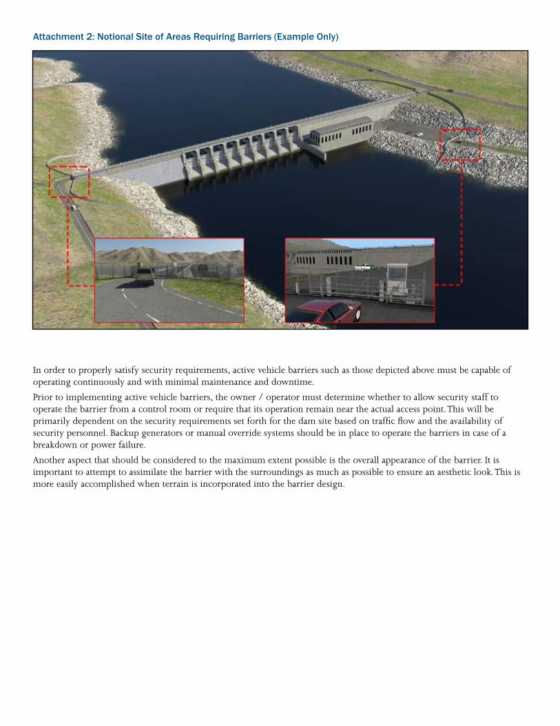
Attachment 2: Notional Site of Areas Requiring Barriers (Example Only)
In order to properly satisfy security requirements, active vehicle barriers such as those depicted above must be capable of operating continuously and with minimal maintenance and downtime.
Prior to implementing active vehicle barriers, the owner / operator must determine whether to allow security staff to operate the barrier from a control room or require that its operation remain near the actual access point. This will be primarily dependent on the security requirements set forth for the dam site based on traffic flow and the availability of security personnel. Backup generators or manual override systems should be in place to operate the barriers in case of a breakdown or power failure.
Another aspect that should be considered to the maximum extent possible is the overall appearance of the barrier. It is important to attempt to assimilate the barrier with the surroundings as much as possible to ensure an aesthetic look. This is more easily accomplished when terrain is incorporated into the barrier design.
Threat
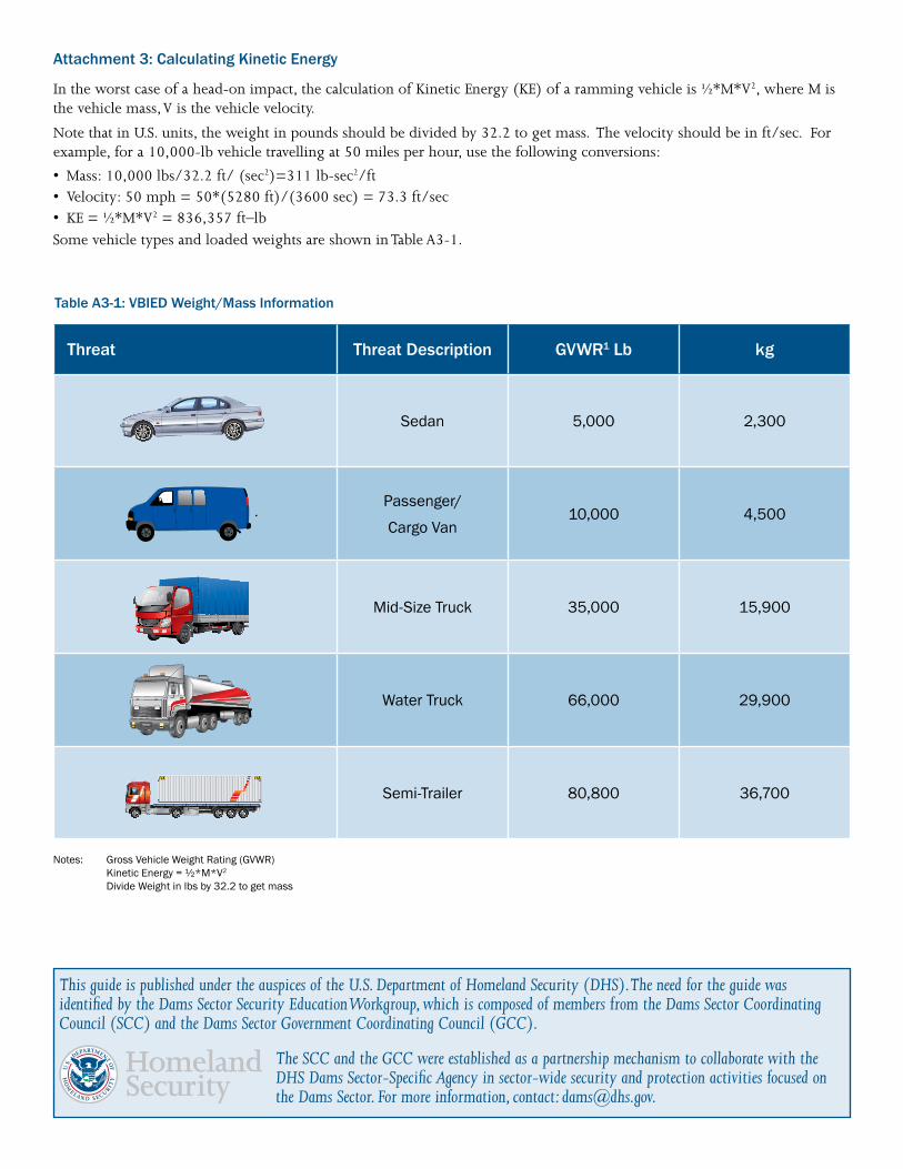
Attachment 3: Calculating Kinetic Energy
In the worst case of a head-on impact, the calculation of Kinetic Energy (KE) of a ramming vehicle is ½*M*V2, where M is the vehicle mass, V is the vehicle velocity.
Note that in U.S. units, the weight in pounds should be divided by 32.2 to get mass. The velocity should be in ft/sec. For example, for a 10,000-lb vehicle travelling at 50 miles per hour, use the following conversions:
• Mass: 10,000 lbs/32.2 ft/ (sec2)=311 lb-sec2/ft • Velocity: 50 mph = 50*(5280 ft)/(3600 sec) = 73.3 ft/sec • KE = ½*M*V2 = 836,357 ft–lb Some vehicle types and loaded weights are shown in Table A3-1.
Table A3-1: VBIED Weight/Mass Information
Threat Description
Sedan
GVWR1 Lb
5,000
kg
2,300
Passenger/
Cargo Van 10,000 4,500
Mid-Size Truck 35,000 15,900
Water Truck 66,000 29,900
Semi-Trailer 80,800 36,700
Notes:
Gross Vehicle Weight Rating (GVWR) Kinetic Energy = ½*M*V2 Divide Weight in lbs by 32.2 to get mass
This guide is published under the auspices of the U.S. Department of Homeland Security (DHS). The need for the guide was identified by the Dams Sector Security Education Workgroup, which is composed of members from the Dams Sector Coordinating Council (SCC) and the Dams Sector Government Coordinating Council (GCC).
The SCC and the GCC were established as a partnership mechanism to collaborate with the DHS Dams Sector-Specific Agency in sector-wide security and protection activities focused on the Dams Sector. For more information, contact: [email protected].