Embed Size (px)
Citation preview
ACSI 1426-04-AO ELECTRIC LATCH RETRACTION
CONTROL SYSTEMS,
ST. LOUIS, MISSOURIINCORPORATED
ARCHITECTURAL
II – 1400-6
CONTROLLER INSTALLATION INSTRUCTIONS
I.D. 1092, REV. C INSTALLATION For C-UL Listed applications, the unit shall be installed in accordance with Part 1 of the Canadian Electrical Code. Transformer model BE31763001 by Basler Electric and transformer model 2010028 by Galaxy Transformer and Magnetics have been certified for UL and C-UL applications. Transformer model A41-130-28A34 by EWC has been certified for UL applications only. The 1426 enclosure should be securely fastened to the wall using the four 1/4 inch diameter mounting holes located in the back of the box. Position the enclosure so that the transformer is located on the left-hand side. The 1426 must not be installed outdoors. For the 120VAC power input, terminal block TB1 will accommodate up to 12 AWG wire (solid). Conduit must be used to provide an adequate earth ground to the enclosure. NOTE: The maximum input current is 750mA. The 1426 is designed to be used with all ACSI 1550 exit devices modified for electric latch retraction. Use the chart below to determine the correct wire gauge per given length of two-conductor cable that will be run from the 1426 to each exit device. Do not exceed the maximum length listed with each wire gauge. WIRE GAUGE MAXIMUM LENGTH OF TWO-CONDUCTOR CABLE 16 AWG 40 FEET 14 AWG 60 FEET 12 AWG 100 FEET
2
Up to two devices can be used with the 1426. If only one device is to be used, wire to the “DEVICE ONE” location at TB3, terminals 5 and 6. NOTE: When using the 1550C exit device with red and black leads, be sure to
observe polarity when connecting devices 1 and 2 to TB3. (Refer to the wiring diagram located on the lid of the controller.)
STANDARD OPERATION The 1426 is provided with two inputs: one used for momentarily retracting latches sequentially, followed by a signal to activate the automatic door operator; the other used with a maintain switch for sequentially retracting latches only. This system will work for single door applications or on a pair of doors using a device on one or both leaves. Connect a momentary, normally open switch across terminals 1 and 2 of terminal block TB3. Closing this switch momentarily will retract the latch of DEVICE ONE and DEVICE TWO sequentially and follow with a dry contact closure signal to the automatic door operator. Pot R2 is used to control the length of time that the latch(es) remain retracted and the signal to the automatic door operator remains active. Factory set to five seconds, pot R2 (located at the top of the p.c. board) can be field adjusted to the desired delay time from 1 to 20 seconds. Turn the pot clockwise to increase the delay time. When using normally open contacts from a keypad or card reader with built-in time delay, turn pot R2 fully counterclockwise to the minimum delay time (approx. 0.5 sec.). A contact closure will activate latch retraction and activate the automatic door operator. The device(s) will latch and the signal to the automatic door operator will cancel within 0.5 second after the keypad or card reader delay times out. NOTE: Pot R4 is not used; do not adjust. Connect a maintain switch across terminals 7 and 8 of terminal block TB3. Closing this switch will sequentially retract the latch of DEVICE ONE and DEVICE TWO, but will not activate the automatic door operator. Upon opening the switch contacts, both devices will immediately latch (no delay before latching). Connect DEVICE ONE to TB3, terminals 5 and 6; positive red lead connects to terminal 5. POLARITY MUST BE OBSERVED WHEN USING THE ELR DEVICE WITH RED & BLACK LEADS. Connect DEVICE TWO, if used, to TB3, terminals 11 and 12; positive red lead connects to terminal 11. (When connecting the alternate1550C exit device with blue leads to terminals 5 and 6 or 11 and 12, polarity is not observed.) The automatic door operator output, TB3, terminals 9
3
and 10, consists of normally open relay contacts that are field wired directly to the “DOOR ACTIVATION” input of the automatic door operator. NOTE: P.C. board program jumper PJ1 must always be left in place between the
middle post and the end post marked “S”. 1550C ELR SOLENOID ASSEMBLIES - THEORY OF OPERATION ACSI provides two types of 1550C ELR (electric latch retraction) devices: One type is designed to fit inside exit devices of narrow height and depth (1-1/4"). The leads to these devices are polarized: Red lead = (+); Black Lead = (-). The other type ELR device will fit into exit devices having a minimum height and depth of 1-1/2". The leads to these devices are non-polarized and colored blue. 1550C ELR Device with Polarized Leads: This device contains a pulse module which delivers a pulse at 24VDC to a high current coil inside the exit device every 6 seconds until the latch is finally pulled back all the way. At this point, a control rod passes over a reflective sensor and signals the module to stop pulsing. There is always an initial pulse that occurs at the moment the system is activated. During the period the system remains activated, output voltage is applied to a low current secondary coil. This coil is responsible for holding the latch in the retracted position until instructed to return to the “fail secure” position. (See note 2 on page 7.) The device contains a fuse to protect the ELR circuit in the event of a reversed polarity wire connection. 1550C ELR Device with Non-polarized Leads: This device contains a powerful solenoid that performs both pulling and holding functions. An initial high current pulse occurs each time output voltage is applied to the device. After the pulse, the solenoid switches over to a "holding" state by way of frequency modulation which reduces the current to allow the solenoid to run at a cooler temperature. Because of its non-polar design, the device contains no fuse. OPERATION WITH FIRE ALARM The 1426 can be wired to the fire alarm relay normally closed contacts. When a fire alarm occurs, any door that is currently unlatched, whether by momentary time delay or by maintained switch, will immediately latch secure. During the time that the fire alarm is active, electronic control of the automatic door opening system by wall switch, card reader, keypad, etc., is disabled. The door then can only be opened manually. The 1426 comes from the factory set up for use without fire alarm interface. If the fire alarm is to be used with this controller, move the program jumper PJ2 from between the middle post and the end post marked “FA DIS” (Fire Alarm
4
Disabled), to between the middle post and the end post marked “FA EN” (Fire Alarm Enabled). NOTE: The current drawn through fire alarm relay contacts will be 120mA @
24VDC AUXILIARY POWER SOURCE OUTPUTS Two constant, power limited auxiliary outputs are provided for powering keypads, motion sensors, annunciator panels, electromagnetic door holders, relays, LEDs, etc. Choose between auxiliary output #1 or auxiliary output #2.
• Auxiliary Output #1 Range: 26.7V - 28.0V, Nominal • Auxiliary Output #2 Range: 12.6V - 16.5V, Nominal
NOTE: Both auxiliary outputs can be used at the same time for loads requiring
different voltages (for a combined maximum load current of 500mA). However, do not tie the aux. output #2 ground (TB3, terminal 18) common to the aux. output #1 ground (TB3, terminal 16). Both of these power sources must be isolated from each other.
CAUTION: IT IS RECOMMENDED TO USE OUTPUT #2 WITH EQUIPMENT
THAT HAVE INPUTS RATED FOR 12 - 24 VOLTS, AC OR DC. CHECK WITH THE MANUFACTURER BEFORE CONNECTING 24VDC RATED EQUIPMENT ACROSS OUTPUT #1 TO ENSURE THE HIGHER VOLTAGE WILL NOT CAUSE ANY DAMAGE.
TYPICAL 1426 APPLICATION A pair of doors is to be controlled by a computerized time system where it is to be unlatched during business hours from 8:00 AM to 5:00 PM. During this time, a handicapped wall switch located on the exterior and interior sides of the door can be used to activate the automatic door operator. After business hours, the computer locks the pair of doors and disables use of the exterior handicapped wall switch. The inside wall switch remains enabled after business hours and, when actuated, will momentarily retract the latches and activate the automatic door operator. To gain entry, a card reader located on the exterior side of the door momentarily retracts the latches and simultaneously enables the outside wall switch to be activated by the handicapped. Refer to the wiring diagrams section for selecting an application that suits the project requirements.
5
TROUBLESHOOTING Before proceeding through the troubleshooting section, ensure that all device latches are not binding against their corresponding strikes. A bound latch can cause sluggish electric retraction or prevent retraction entirely. Power Limited Outputs All outputs to the 1426 are power limited. Depending on the output, if a short circuit or an over load condition should occur, the output will either shut off entirely or go into a safe current limiting state. IMPORTANT!: THE MAXIMUM RATED LOAD FOR ALL OUTPUTS
COMBINED IS 2.0 AMPS, INCLUDING 250mA (MAX.) FOR EACH AUXILIARY OUTPUT.
The outputs to ELR Device One (TB3, terminals 5 & 6) and ELR Device Two (TB3, terminals 11 & 12) will completely shut down to 0 volts when a short circuit across the output occurs or when the load exceeds 5 amps. To reset the output, the short circuit or overload must first be located and removed. Next, momentarily switch off the outputs by opening the contacts across input terminals 1 & 2 or 7 &8, whichever is used. Before switching outputs back on, ensure the load does not exceed the maximum current ratings. Both auxiliary outputs will go into a current limiting state when the load exceeds approximately 2.0 amps or in the event of a short circuit. The current is reduced to a safe level when either of these conditions occur. The output voltage will automatically return to its normal level when the short circuit or overload condition is removed and replaced by a load falling under the maximum current rating. Symptom: Neither DEVICE ONE nor DEVICE TWO retracts after the control switch is activated Possible Causes: 1. The power limited output to Device 1 or Device 2 (or both) may have shut
down. When this happens, the field wires that are run to the exit device are probably shorted together against the conduit, door frame or electric hinge.
6
2. If using the 1550C ELR device with polarized leads, the slow blow 4 amp fuse (Littelfuse #239.004) inside the exit device has blown. The most likely cause would be reversed polarity of the exit device red and black leads: RED = “+”; BLACK = “-”. (Refer to the wiring diagram for proper connection.) Other possible causes may be shorted wires in the solenoid assembly or a defective pulse module.
3. An open connection in the field wiring between the power supply and control
switch used for activating latch retraction. 4. A defective control switch. 5. An open connection in the field wiring between the power supply and exit
device. 6. There may be no pulse. To check for pulses, prop the door open and connect
a voltmeter across the red and black leads coming from the exit device (red lead is positive), or across the blue leads if using the alternate non-polarized 1550C ELR device. Next, connect a jumper wire across terminals 1 and 2 of TB3 to keep DEVICE ONE in a continuous retracted state. If the voltmeter measures between 30 and 40 VDC at the moment the jumper wire was installed, but the latch did not budge, then no initial pulse was generated. For the polarized 1550C ELR device, check for a series of timed pulses that will occur approximately every six seconds. (Make sure that the control rod is not positioned over the reflective sensor on the pulse module when making this next check.) Wait for about 20 seconds to see if the latch pulls in. If it still does not respond, then it indicates the pulse module is inoperative and the entire solenoid/module assembly must be replaced.
Symptom: When 120 volts is applied to TB1, the exit devices will momentarily retract; but if they remain retracted for longer than 20 seconds, then it signals a problem. Possible Causes: 1. Field wiring between the power supply and control switch are shorted
together against the conduit or switch mounting box. 2. A maintain switch is being used and is in the closed position. 3. A defective control switch.
7
Symptom (for polarized 1550C ELR devices only): A noticeable buzzing sound at equal intervals is coming from inside the exit device while in its fully retracted state. Possible Causes: 1. The latch is binding against its corresponding strike and preventing it from
fully retracting, due to misalignment between the latch and strike opening. 2. A defective pulse module For Service or Technical Support, call Architectural Control Systems, Inc.
at (800) 753-5558. NOTE 1: THIS UNIT IS LISTED AS AN EXIT DEVICE CONTROL UNIT TO
UL294 REQUIREMENTS. NOTE 2: THE POWER OUTPUT OF THE CONTROLLER IS OF A FAIL
SECURE DESIGN. THE EXIT DEVICE REMAINS LATCHED DURING A COMPLETE POWER FAILURE, BUT ALWAYS ALLOWS FREE MECHANICAL EGRESS. LISTED PANIC HARDWARE MAY BE REQUIRED TO ALLOW EMERGENCY EXIT. CONSULT LOCAL AUTHORITY HAVING JURISDICTION.
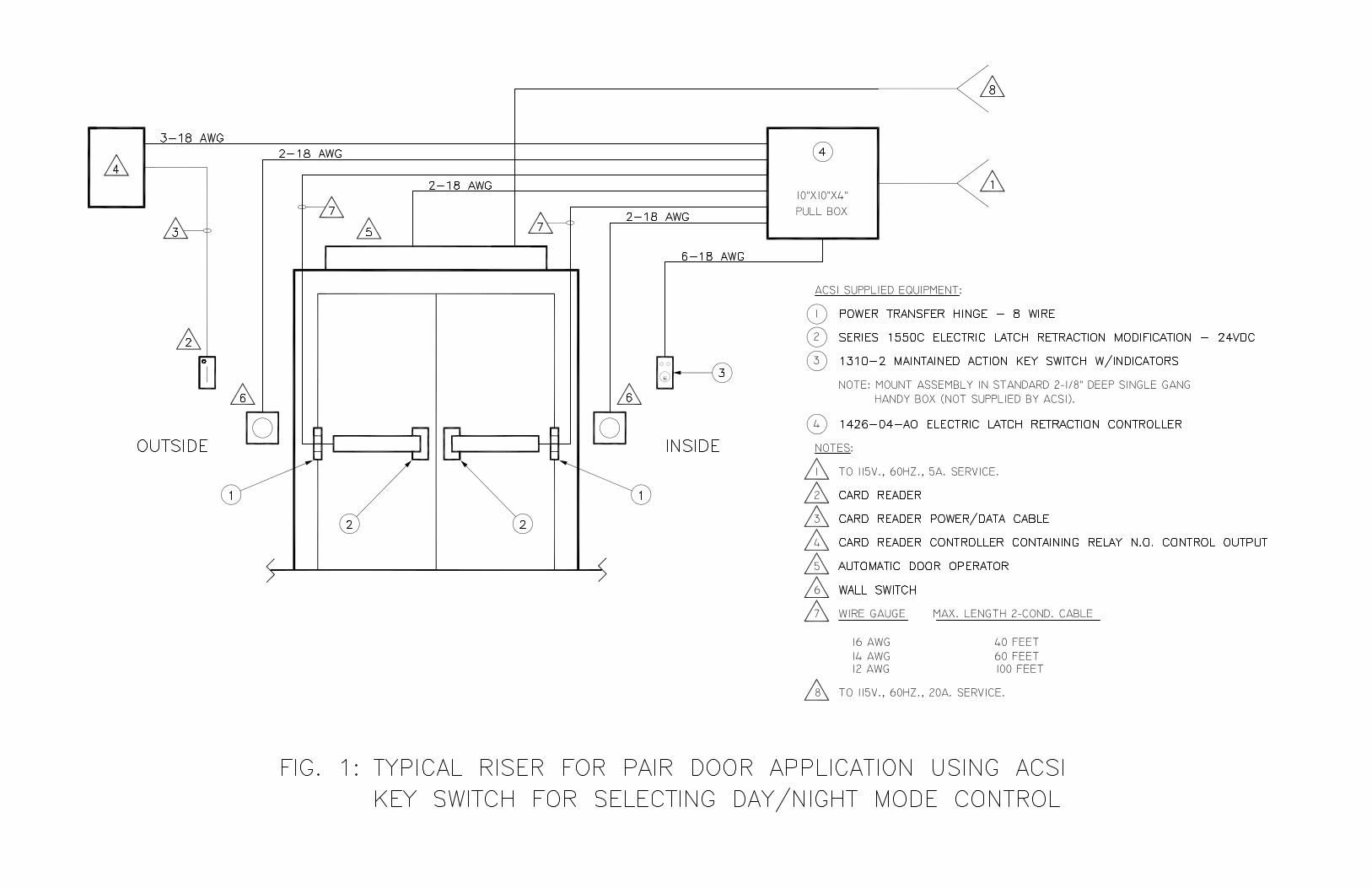
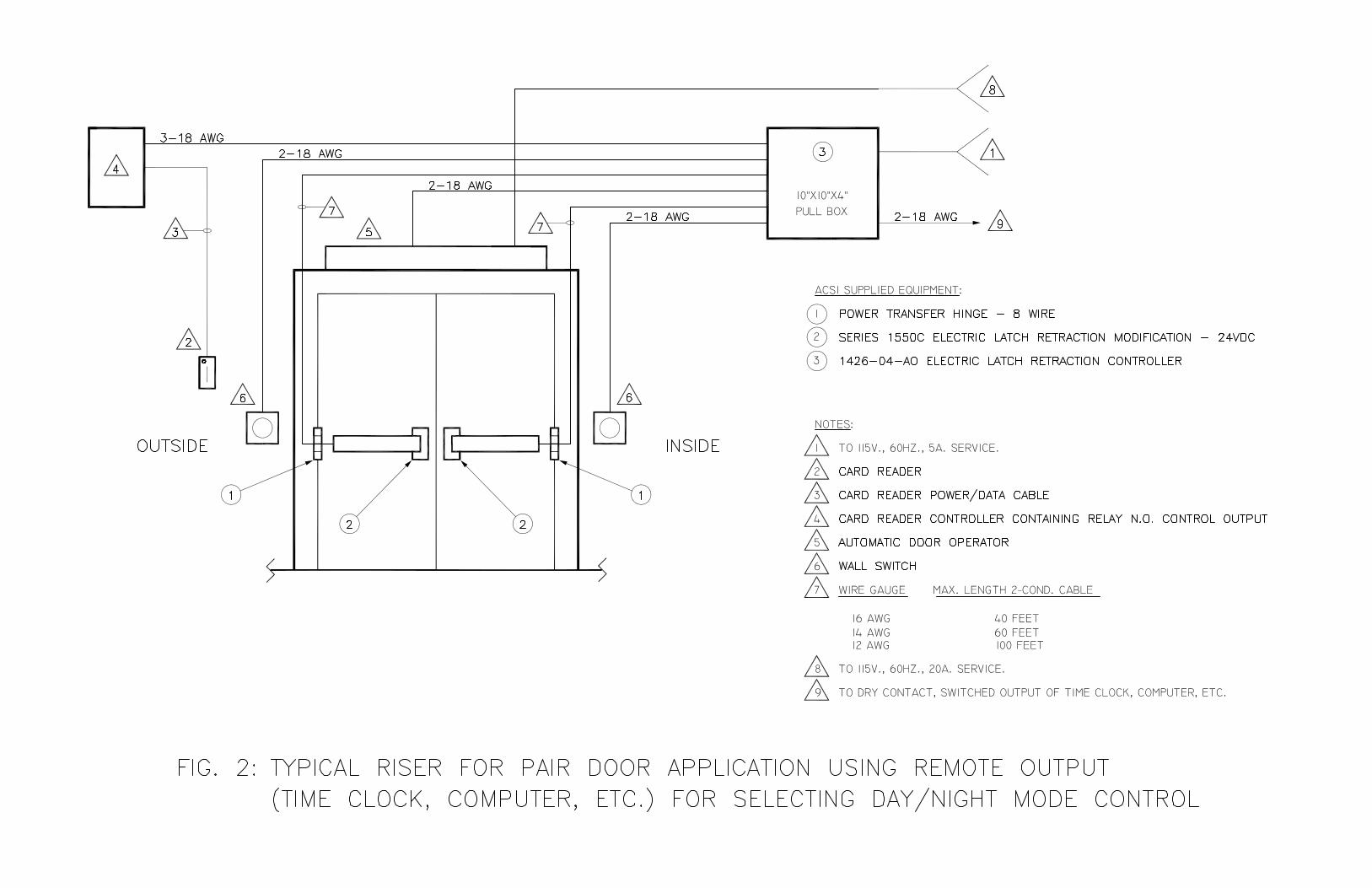
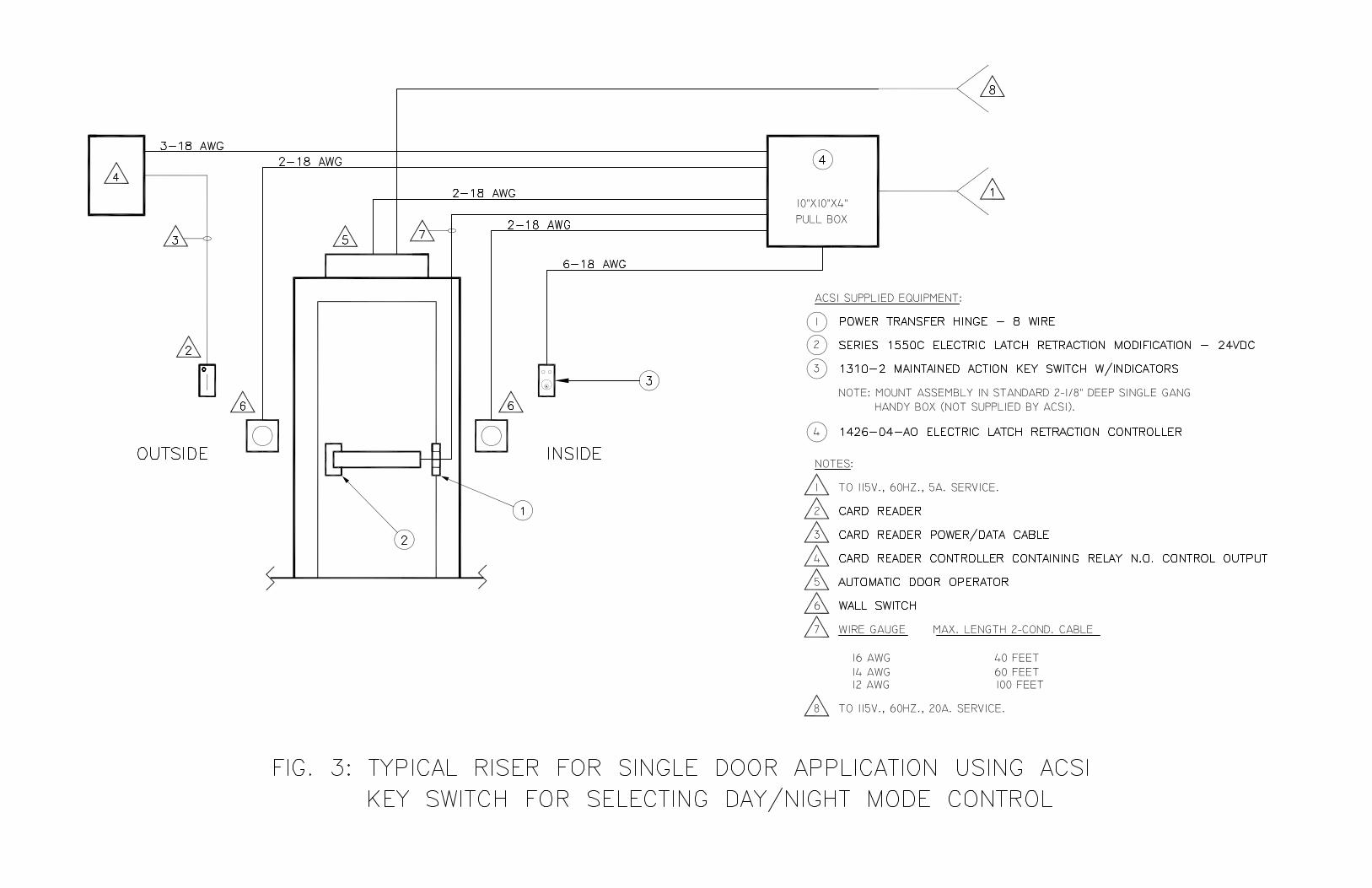
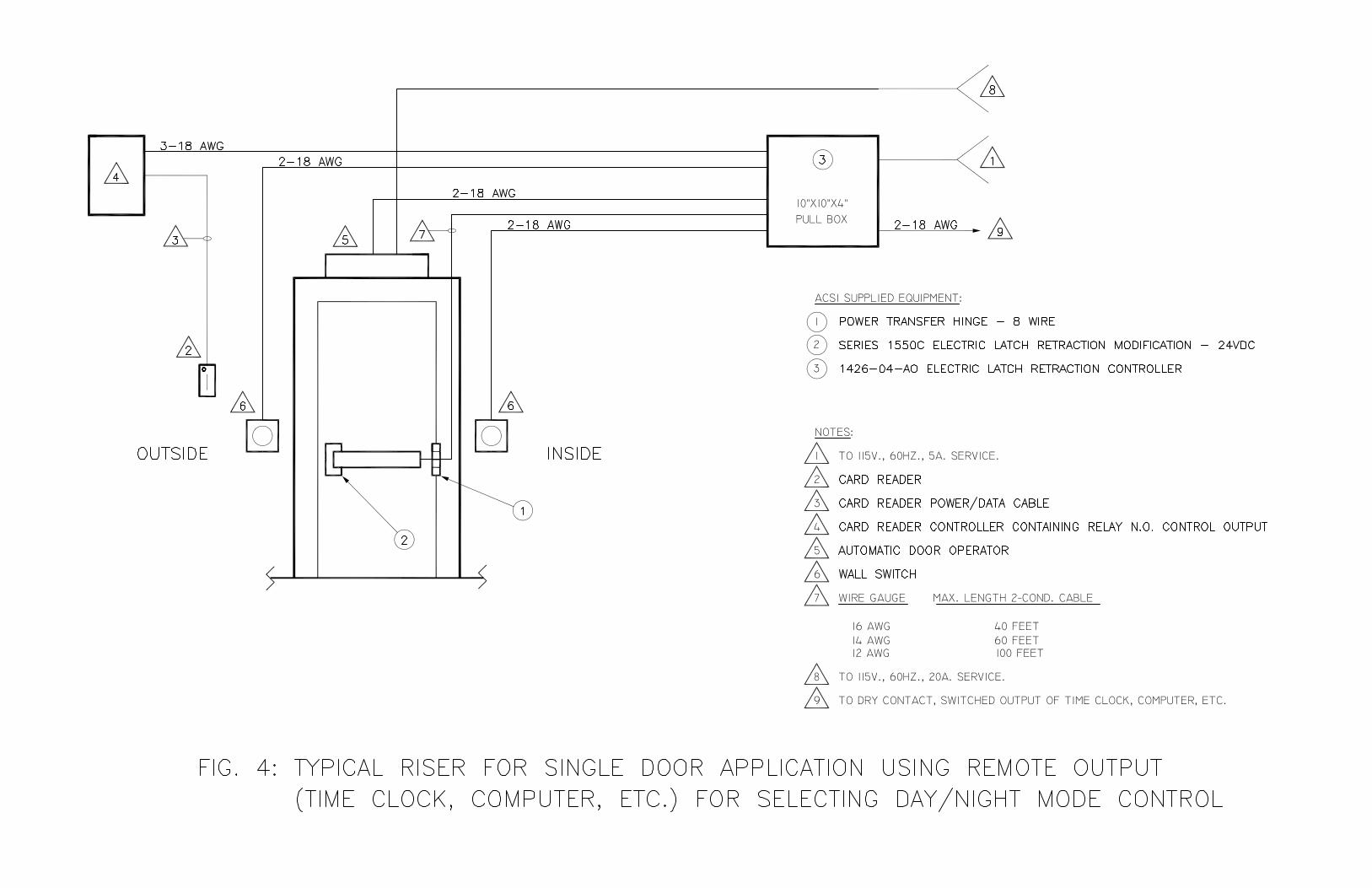
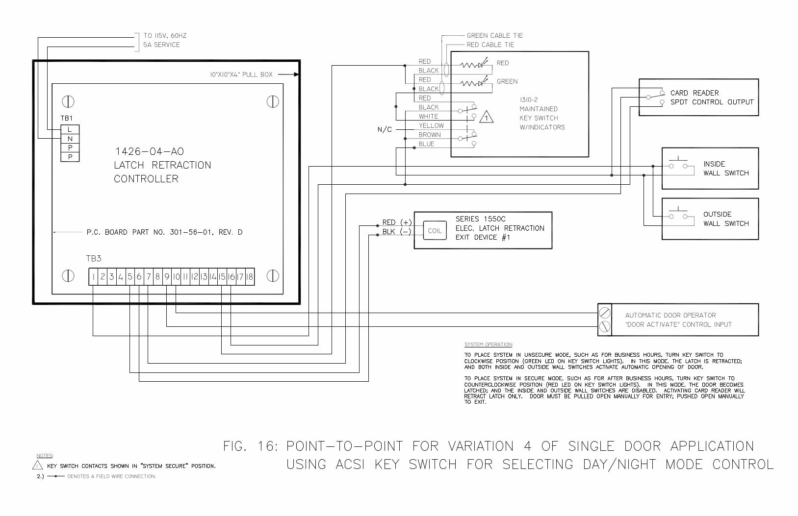
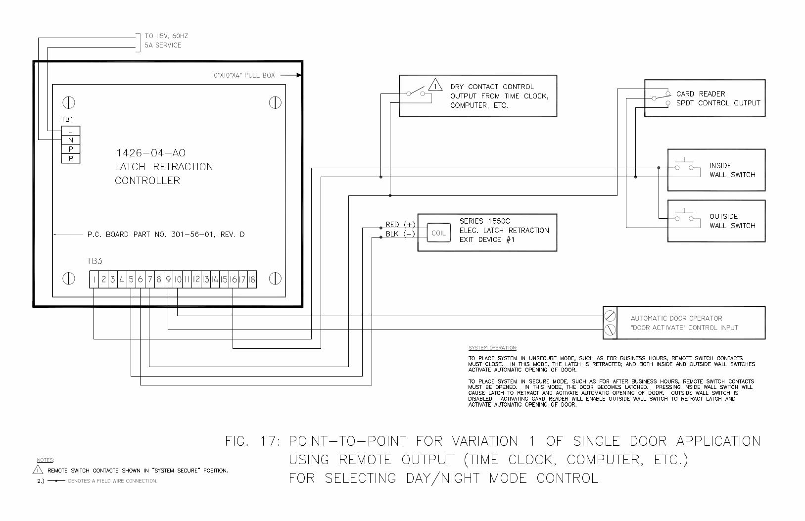
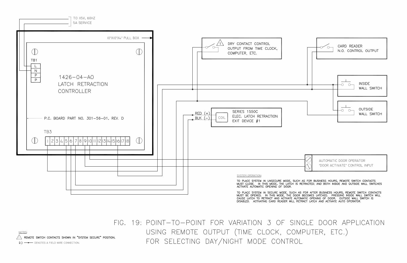
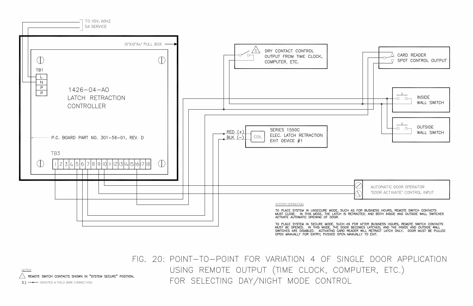
1426-04-AO WIRING DIAGRAMS FOR VARIOUS SINGLE DOOR AND PAIR DOOR APPLICATIONS
(REV. A)
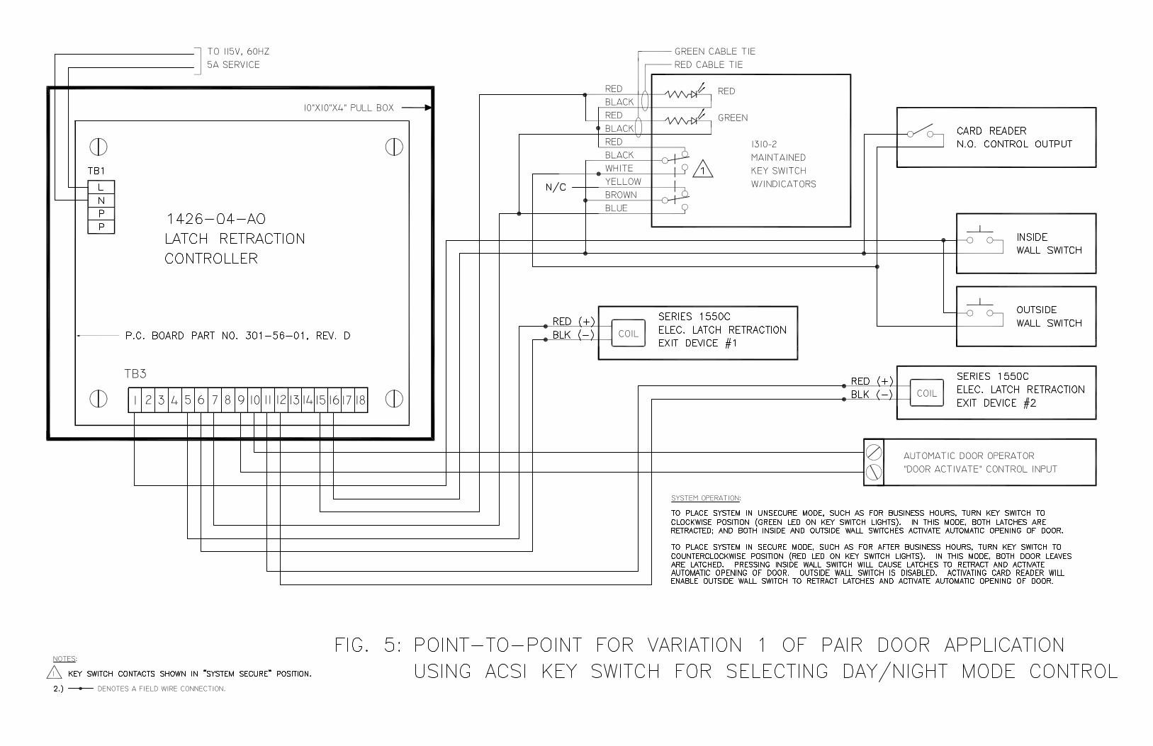
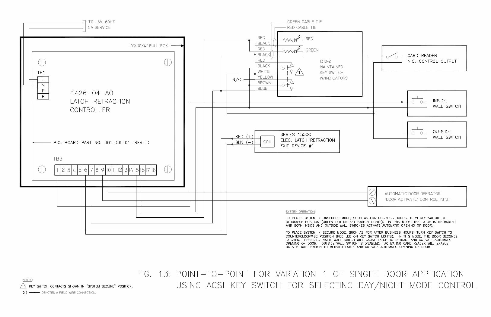
Riser diagrams for typical single door and pair door system configurations have been included. All wiring diagrams are divided into two main categories for selection of day/night mode control: applications using ACSI maintain action key switch w/status indicators, p/n 1310-2; and applications involving interface with a remote output, such as a time clock or computer. For each door type and method of selection category there are four variations of point-to-point wiring diagrams. All variations involve different ways in which the exterior card reader, exterior wall switch and interior wall switch can be used in conjunction with the electrified exit device(s) and automatic door operator when selected for night mode of operation. Below is a brief description describing each variation. Variation 1: Pressing inside wall switch will cause latch(es) to retract and
activate automatic opening of door. Outside wall switch is disabled. Activating card reader will enable outside wall switch to retract latch(es) and activate automatic opening of door.
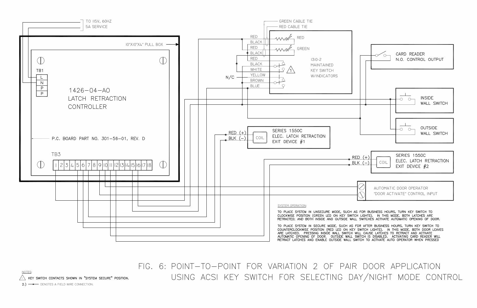
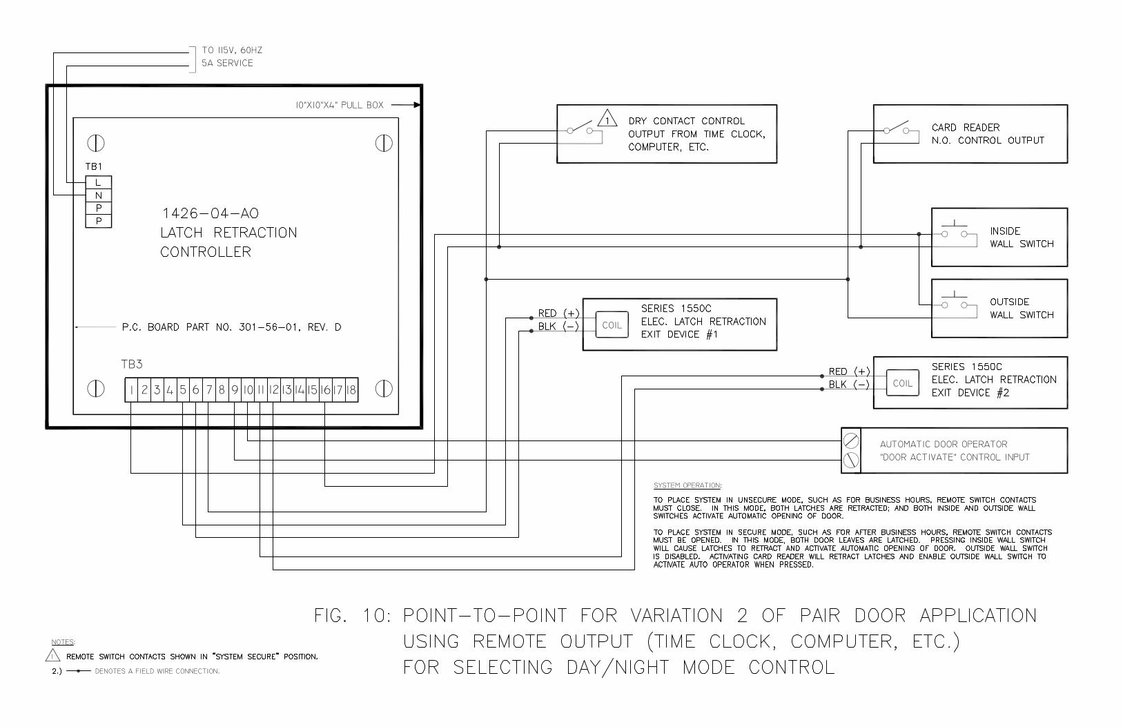
Variation 2: Pressing inside wall switch will cause latch(es) to retract and
activate automatic opening of door. Outside wall switch is disabled. Activating card reader will retract latch(es) and enable outside wall switch to activate auto operator when pressed.
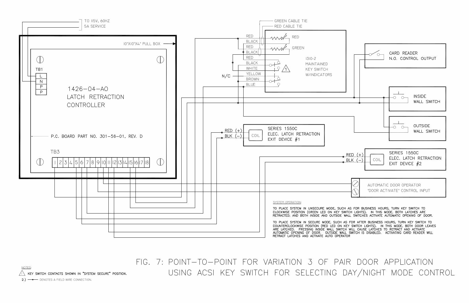
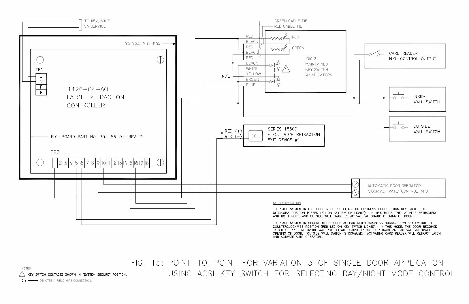
Variation 3: Pressing inside wall switch will cause latch(es) to retract and
activate automatic opening of door. Outside wall switch is disabled. Activating card reader will retract latch(es) and activate auto operator.
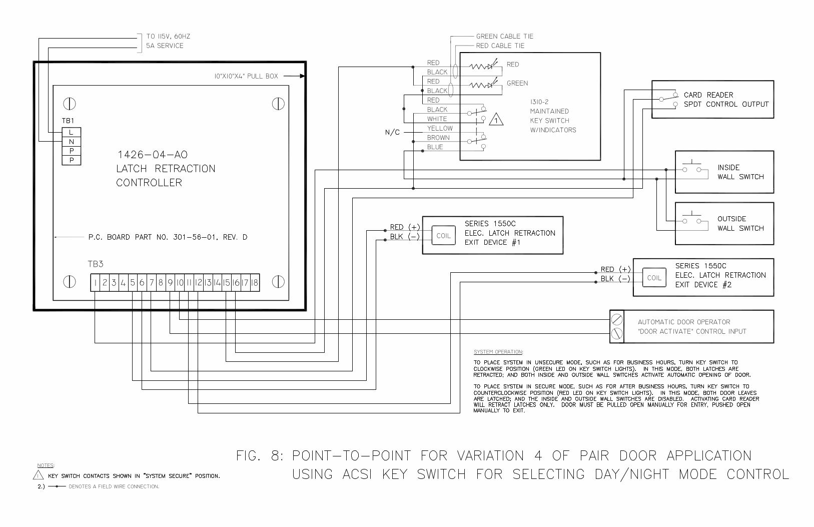
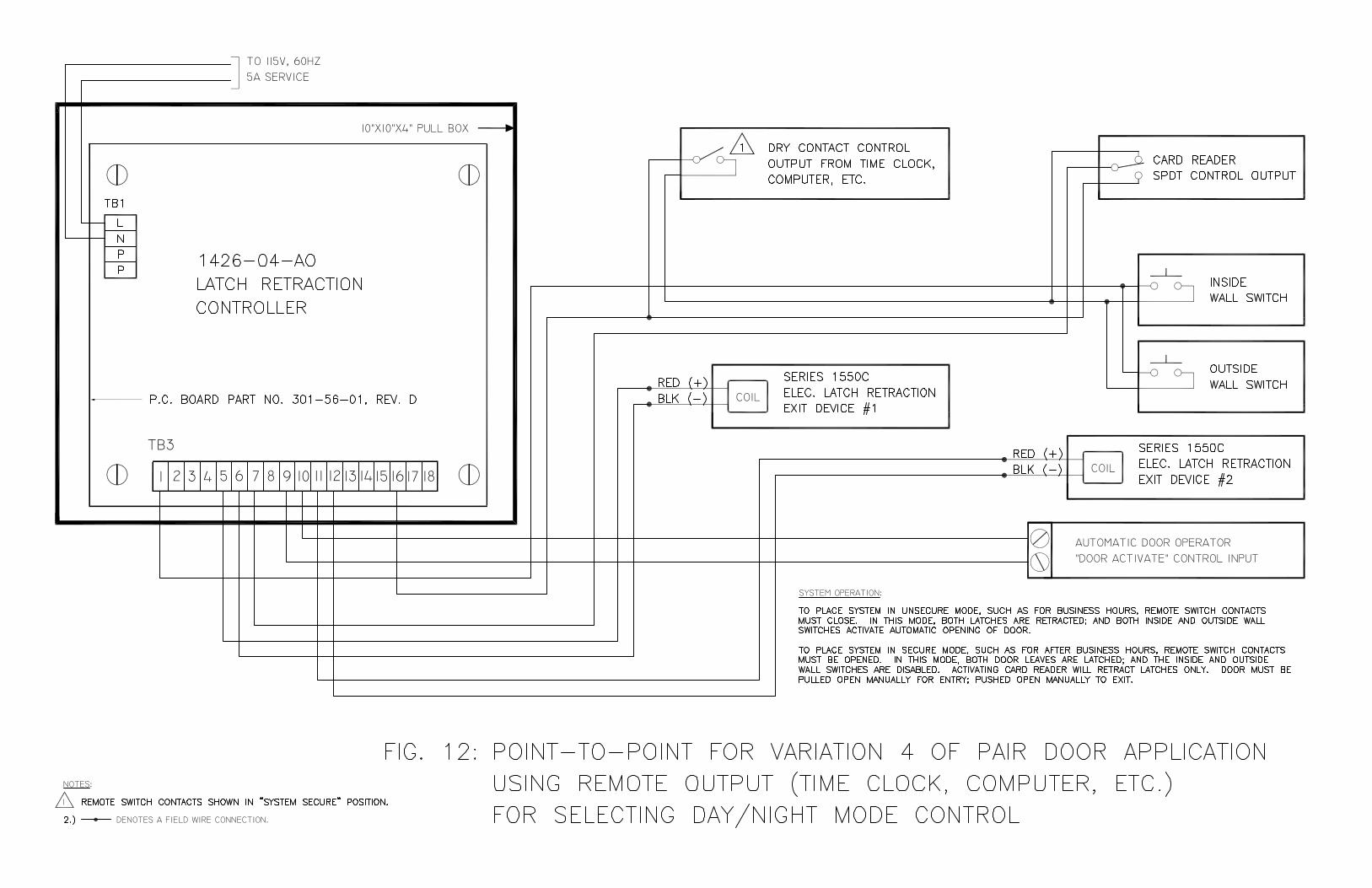
Variation 4: Both inside and outside wall switches are disabled. Activating card
reader will retract latch(es) only. Door must be pulled open manually for entry; pushed open manually to exit.
A more detailed description of system operation for each variation can be found on the point-to-point wiring diagrams to follow.
Note: All point-to-point wiring diagrams on the following pages show the 1550C ELR Device with polarized red and black leads connected to TB3, terminals 5 and 6 and/or 11 and 12. When using the alternate 1550C ELR Device with nonpolarized leads, connect the blue wires to TB3, terminals 5 and 6 and/or 11 and 12.