Embed Size (px)
Citation preview
©C
opyr
ight
11/
30/2
010
AB
B.
All
right
s re
serv
ed.
Help
Product specification
ABB industrial drives,
ACS800-11
Welcome to the Product specification training module for the ACS800-11, ABB Industrial drive.
If you need help navigating this module, please click the Help button in the top right corner. To view the presenter notes as text, please click the Notes button in the bottom right corner.
©C
opyr
ight
11/
30/2
010
AB
B.
All
right
s re
serv
ed. -
2-
Help
Objectives
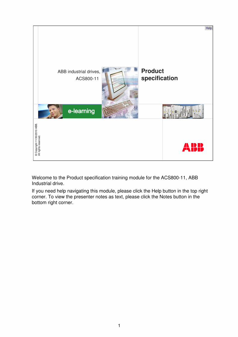
� Present the key features of the ACS800-11
After completing this module, you will be able to
After completing this module, you will be able to present the key features of the ACS800-11.
©C
opyr
ight
11/
30/2
010
AB
B.
All
right
s re
serv
ed. -
3-
Help
Main features
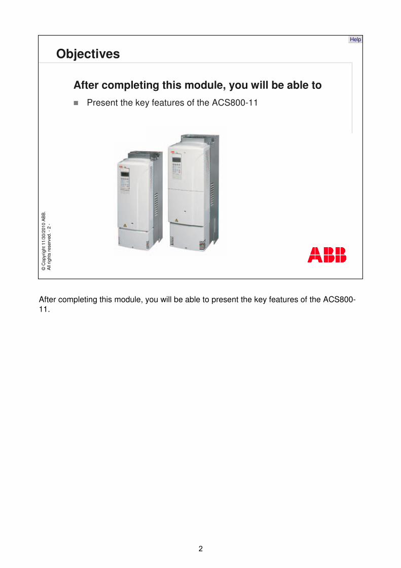
� Part of the ABB industrial drives product portfolio
� ACS800-11: the regenerative drive
� Flexible and programmable drive
� Wall-mounted
� Wide range of powers and voltages
� Compact and complete drive
– Drive options built in
� Fast and easy to install
The ACS800-11 belongs to the ABB industrial drives product portfolio. It isa regenerative wall mounted drive that can feed braking energy from the motor back to the supply network. It looks and feels like other ACS800 drives. Therefore it is a highly flexible AC drive that can be configured to meet the precise needs of industrial applications.
It is a wall-mounted drive and has a wide range of powers and voltages. It is a compact and complete drive with all the necessary drive options built in. The drive is also fast and easy to install.
©C
opyr
ight
11/
30/2
010
AB
B.
All
right
s re
serv
ed. -
4-
Help
Mains connection
� Supply voltages– 3-phase, U2IN= 208 to 240 V, ±10%
– 3-phase, U3IN= 380 to 415 V, ±10%
– 3-phase, U5IN= 380 to 500 V, ±10%
– 3-phase, U7IN= 525 to 690 V, ±10%
� Supply frequency range 48-63 Hz
� Unity power factor– 1 (fundamental)
– 1 (total)
� Current THD <5% at supply
� Suitable for floating (IT) network
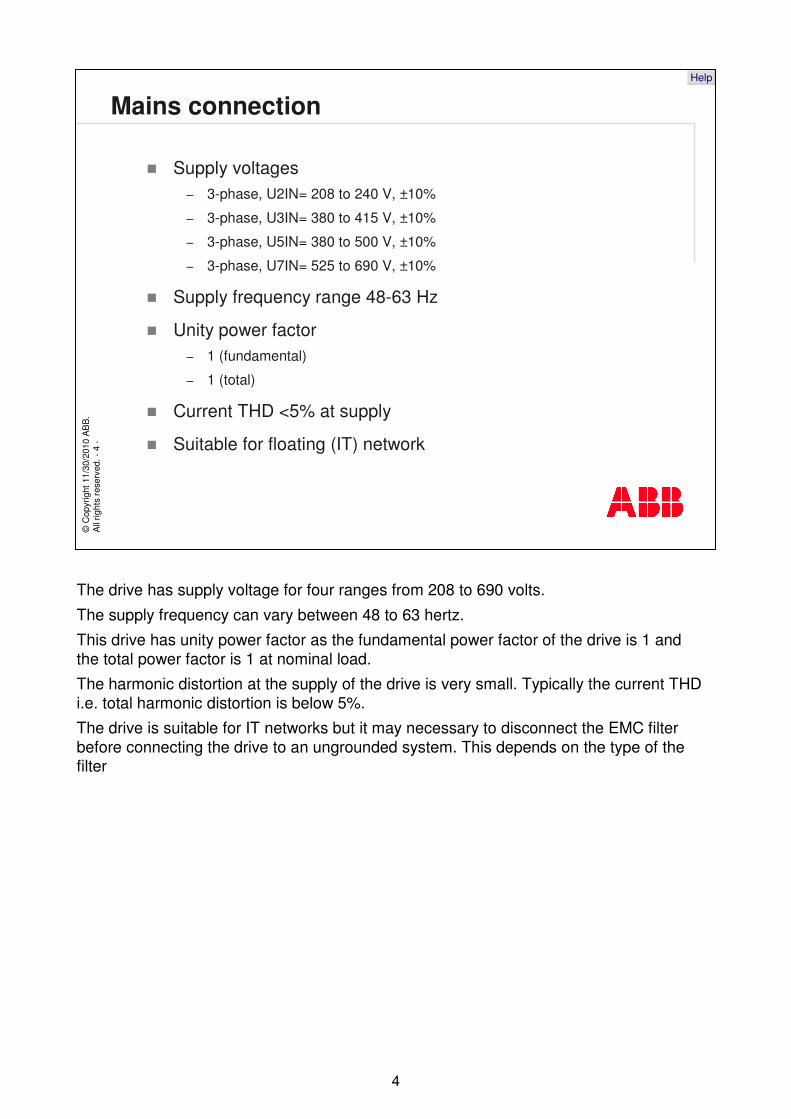
The drive has supply voltage for four ranges from 208 to 690 volts.
The supply frequency can vary between 48 to 63 hertz.
This drive has unity power factor as the fundamental power factor of the drive is 1 and the total power factor is 1 at nominal load.
The harmonic distortion at the supply of the drive is very small. Typically the current THD i.e. total harmonic distortion is below 5%.
The drive is suitable for IT networks but it may necessary to disconnect the EMC filter before connecting the drive to an ungrounded system. This depends on the type of the filter
©C
opyr
ight
11/
30/2
010
AB
B.
All
right
s re
serv
ed. -
5-
Help
Motor connection
� ACS800-11 power and voltage range– 5,5 - 45 kW / (3~ 208 V to 240 V supply)
– 11 - 90 kW / (3~ 380 V to 415 V supply)
– 15 - 110 kW / (3~ 380 V to 500 V supply)
– 37 - 90 kW / (3~ 525 V to 690 V supply)
� Frequency 0 to 300 Hz
� Field weakening point adjustable from 8 to 300 Hz
� Motor control is ABB’s Direct Torque Control (DTC)
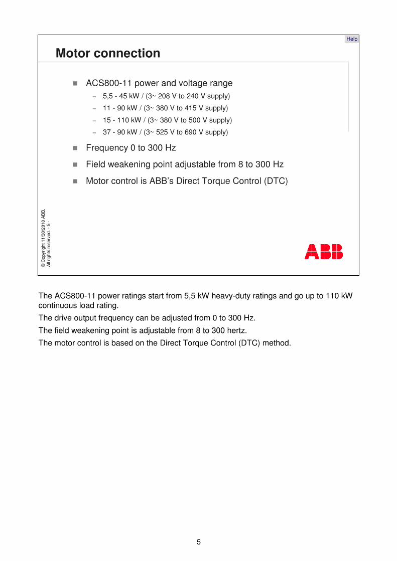
The ACS800-11 power ratings start from 5,5 kW heavy-duty ratings and go up to 110 kW continuous load rating.
The drive output frequency can be adjusted from 0 to 300 Hz.
The field weakening point is adjustable from 8 to 300 hertz.
The motor control is based on the Direct Torque Control (DTC) method.
©C
opyr
ight
11/
30/2
010
AB
B.
All
right
s re
serv
ed. -
6-
Help
Ratings
Construction Rating (size)
Nominal ratings Typical ratings Heavy-duty ratings
Supply voltageProduct type
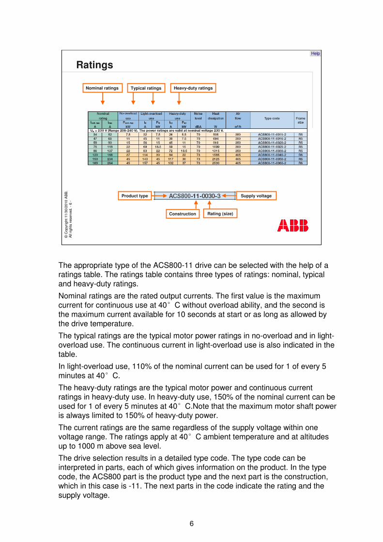
The appropriate type of the ACS800-11 drive can be selected with the help of a ratings table. The ratings table contains three types of ratings: nominal, typical and heavy-duty ratings.
Nominal ratings are the rated output currents. The first value is the maximum current for continuous use at 40 C without overload ability, and the second is the maximum current available for 10 seconds at start or as long as allowed by the drive temperature.
The typical ratings are the typical motor power ratings in no-overload and in light-overload use. The continuous current in light-overload use is also indicated in the table.
In light-overload use, 110% of the nominal current can be used for 1 of every 5 minutes at 40 C.
The heavy-duty ratings are the typical motor power and continuous current ratings in heavy-duty use. In heavy-duty use, 150% of the nominal current can be used for 1 of every 5 minutes at 40 C.Note that the maximum motor shaft power is always limited to 150% of heavy-duty power.
The current ratings are the same regardless of the supply voltage within one voltage range. The ratings apply at 40 C ambient temperature and at altitudes up to 1000 m above sea level.
The drive selection results in a detailed type code. The type code can be interpreted in parts, each of which gives information on the product. In the type code, the ACS800 part is the product type and the next part is the construction, which in this case is -11. The next parts in the code indicate the rating and the supply voltage.
©C
opyr
ight
11/
30/2
010
AB
B.
All
right
s re
serv
ed. -
7-
Help
Dimensions and weights
R5R6
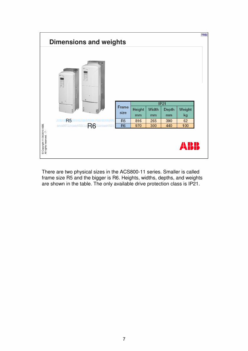
There are two physical sizes in the ACS800-11 series. Smaller is called frame size R5 and the bigger is R6. Heights, widths, depths, and weights are shown in the table. The only available drive protection class is IP21.
©C
opyr
ight
11/
30/2
010
AB
B.
All
right
s re
serv
ed. -
8-
Help
Environmental limits
� Operating temperature– From -15 to +50°C, no frost allowed
– From +40 to +50°C at reduced output current (1% / 1°C)
� Operating altitude– Up to 1000 m without derating
– For 230 to 500 V units, from 1000 to 4000 m with derating (1% /100 m)
– For 690 V units, from 1000 to 2000 m with derating (1% / 100 m)
� Relative humidity– 5 to 95%, no condensation allowed
� Degree of protection – Standard degree of protection IP21
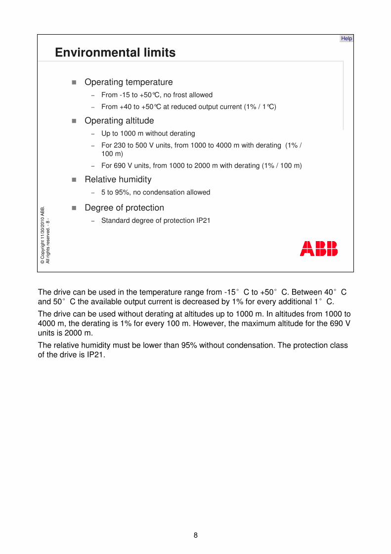
The drive can be used in the temperature range from -15 C to +50 C. Between 40 C and 50 C the available output current is decreased by 1% for every additional 1 C.
The drive can be used without derating at altitudes up to 1000 m. In altitudes from 1000 to 4000 m, the derating is 1% for every 100 m. However, the maximum altitude for the 690 V units is 2000 m.
The relative humidity must be lower than 95% without condensation. The protection class of the drive is IP21.
©C
opyr
ight
11/
30/2
010
AB
B.
All
right
s re
serv
ed. -
9-
Help
Connectivity
� Standard analog and digital I/O channels
� Extension options (connected as plug-in modules)– Analog and digital I/O modules
– Fieldbus modules
– Pulse encoder interface modules
Digital I/O Extensions (up to 13 DI and 9 RO)Analog I/O Extensions (up to 5 AI and 4 AO)
Pulse Encoder Adapter
7 Digital inputs
3 Analog inputs 2 Analog outputs
3 Relay outputs
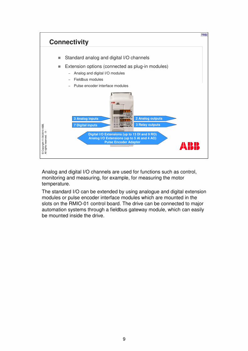
Analog and digital I/O channels are used for functions such as control, monitoring and measuring, for example, for measuring the motor temperature.
The standard I/O can be extended by using analogue and digital extension modules or pulse encoder interface modules which are mounted in the slots on the RMIO-01 control board. The drive can be connected to major automation systems through a fieldbus gateway module, which can easily be mounted inside the drive.
©C
opyr
ight
11/
30/2
010
AB
B.
All
right
s re
serv
ed. -
10-
Help
Specifications of Standard I/O
� Standard I/O on the RMIO-01 control board
Connectivity
– 3 analog inputs� Differential and
galvanically isolated into a group
� Common mode voltage ±15 V
� One ±0(2) -10 V, resolution 12 bit
� Two 0(4) - 20 mA, resolution 11 bit
– 2 analog outputs� 0(4) - 20 mA, resolution
10 bit
– 7 digital inputs� Galvanically isolated
into a group with input voltage 24 V DC and filtering (HW) time 1 ms
– 3 relay (digital) outputs� 24 V DC or 115/230 V AC
� Max. continuous current 2 A with changeover contact
– Reference voltage output� ±10 V ±0.5%, max. 10 mA
– Auxiliary power supply output � +24 V ±10%, max. 250 mA
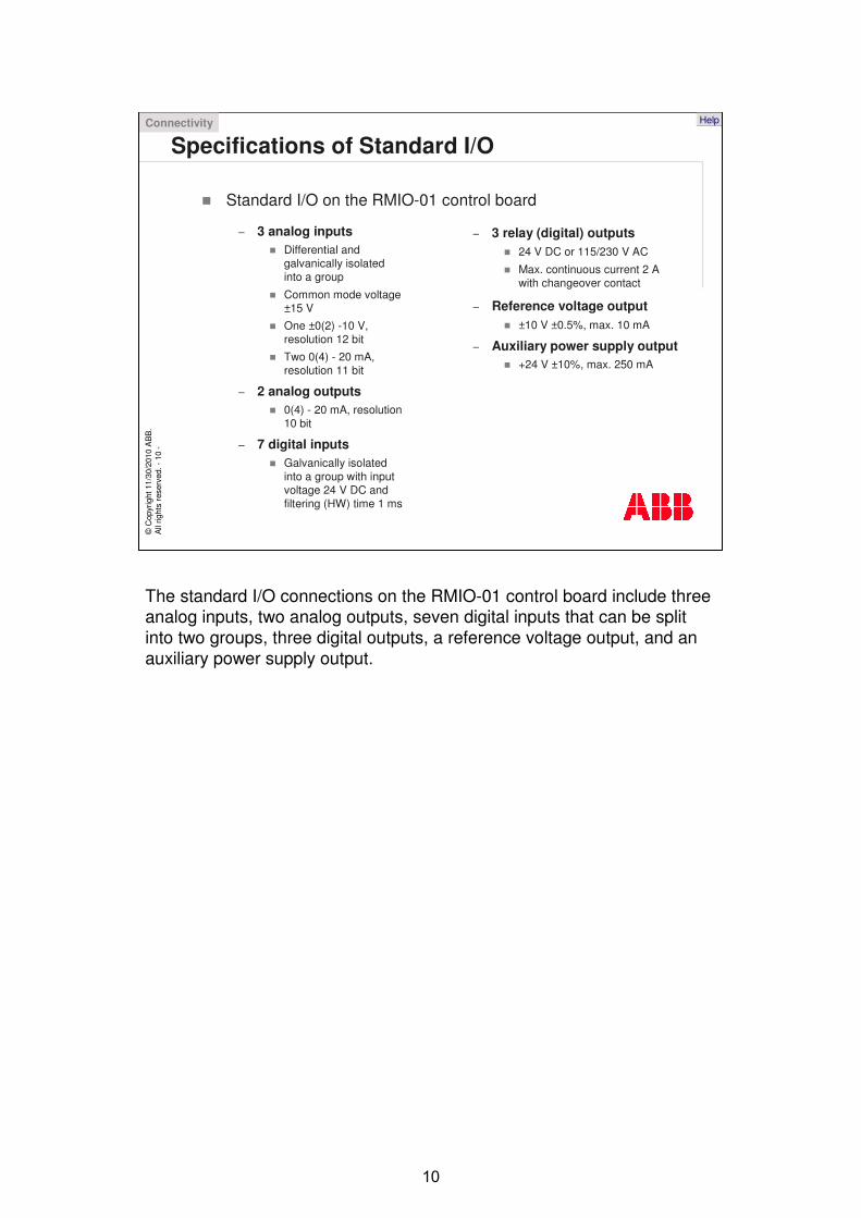
The standard I/O connections on the RMIO-01 control board include three analog inputs, two analog outputs, seven digital inputs that can be split into two groups, three digital outputs, a reference voltage output, and an auxiliary power supply output.
©C
opyr
ight
11/
30/2
010
AB
B.
All
right
s re
serv
ed. -
11-
Help
Specifications of Optional I/O� Analog I/O extension module RAIO-01 (+L500)
� 2 analog inputs– Galvanically isolated from 24 V supply and ground
– ±0(2) - 10 V, 0(4) - 20 mA or ±0 - 2 V, resolution 12 bits
� 2 analog outputs– Galvanically isolated from 24 V supply and ground
– 0(4) - 20 mA, resolution 12 bits
� Digital I/O extension module RDIO-01 (+L501)� 3 digital inputs
– Individually galvanically isolated
– Signal level 24 to 250 V or 115/230 V AC
� 2 relay outputs– Switchover contact
– 24 V or 115/230 V AC, max. 2 A
� Pulse encoder interface module RTAC-01 (+L502)� 1 incremental encoder input
– Channels A, B and Z (zero pulse)
– Signal level and power supply for the encoder is 24 or 15 V
– Single ended or differential inputs
– Maximum input frequency 200 kHz
Connectivity
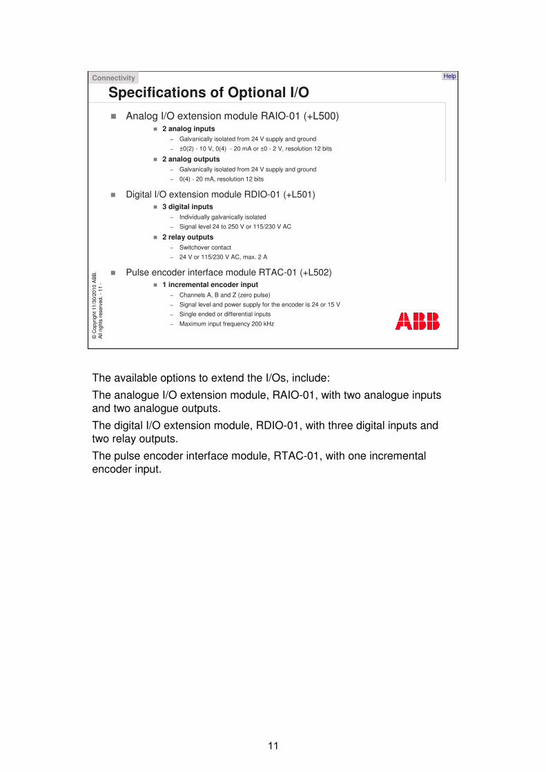
The available options to extend the I/Os, include:
The analogue I/O extension module, RAIO-01, with two analogue inputs and two analogue outputs.
The digital I/O extension module, RDIO-01, with three digital inputs and two relay outputs.
The pulse encoder interface module, RTAC-01, with one incremental encoder input.
©C
opyr
ight
11/
30/2
010
AB
B.
All
right
s re
serv
ed. -
12-
Help
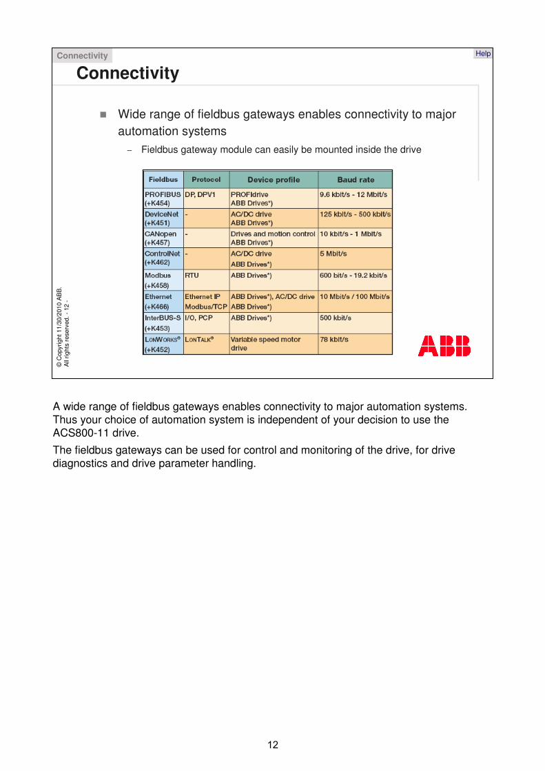
Connectivity
� Wide range of fieldbus gateways enables connectivity to major automation systems
– Fieldbus gateway module can easily be mounted inside the drive
Connectivity
A wide range of fieldbus gateways enables connectivity to major automation systems. Thus your choice of automation system is independent of your decision to use the ACS800-11 drive.
The fieldbus gateways can be used for control and monitoring of the drive, for drive diagnostics and drive parameter handling.
©C
opyr
ight
11/
30/2
010
AB
B.
All
right
s re
serv
ed. -
13-
Help
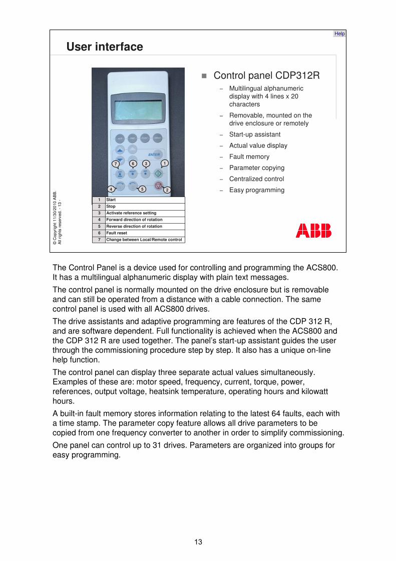
User interface
1
2
3
4 5
67
� Control panel CDP312R– Multilingual alphanumeric
display with 4 lines x 20 characters
– Removable, mounted on the drive enclosure or remotely
– Start-up assistant
– Actual value display
– Fault memory
– Parameter copying
– Centralized control
– Easy programming1 Start
2 Stop
3 Activate reference setting
4 Forward direction of rotation
5 Reverse direction of rotation
6 Fault reset
7 Change between Local/Remote control
The Control Panel is a device used for controlling and programming the ACS800. It has a multilingual alphanumeric display with plain text messages.
The control panel is normally mounted on the drive enclosure but is removable and can still be operated from a distance with a cable connection. The same control panel is used with all ACS800 drives.
The drive assistants and adaptive programming are features of the CDP 312 R, and are software dependent. Full functionality is achieved when the ACS800 and the CDP 312 R are used together. The panel’s start-up assistant guides the user through the commissioning procedure step by step. It also has a unique on-line help function.
The control panel can display three separate actual values simultaneously. Examples of these are: motor speed, frequency, current, torque, power, references, output voltage, heatsink temperature, operating hours and kilowatt hours.
A built-in fault memory stores information relating to the latest 64 faults, each with a time stamp. The parameter copy feature allows all drive parameters to be copied from one frequency converter to another in order to simplify commissioning.
One panel can control up to 31 drives. Parameters are organized into groups for easy programming.
©C
opyr
ight
11/
30/2
010
AB
B.
All
right
s re
serv
ed. -
14-
Help
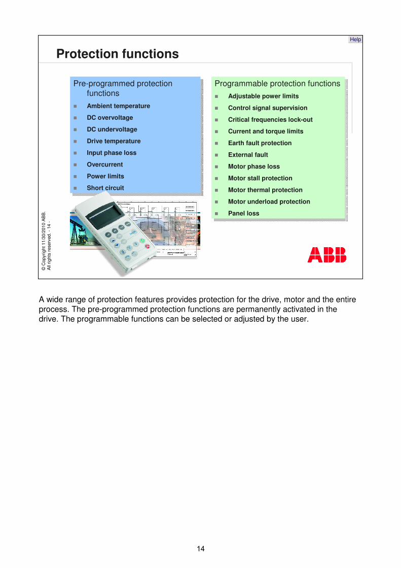
Protection functions
Programmable protection functions� Adjustable power limits
� Control signal supervision
� Critical frequencies lock-out
� Current and torque limits
� Earth fault protection
� External fault
� Motor phase loss
� Motor stall protection
� Motor thermal protection
� Motor underload protection
� Panel loss
Pre-programmed protection functions
� Ambient temperature
� DC overvoltage
� DC undervoltage
� Drive temperature
� Input phase loss
� Overcurrent
� Power limits
� Short circuit
Pre-programmed protection functions
� Ambient temperature
� DC overvoltage
� DC undervoltage
� Drive temperature
� Input phase loss
� Overcurrent
� Power limits
� Short circuit
A wide range of protection features provides protection for the drive, motor and the entire process. The pre-programmed protection functions are permanently activated in thedrive. The programmable functions can be selected or adjusted by the user.
©C
opyr
ight
11/
30/2
010
AB
B.
All
right
s re
serv
ed. -
15-
Help
Product compliance
� CE labeling– EMC Directive - compliance
– Low Voltage directive - compliance
– Machinery Directive - incorporation
� UL– UL508C
� CSA– C22 No. 14-95
A CE label is attached to the drive to verify that the unit follows the provisions of the European Low Voltage and EMC Directives. The compliance with the Low Voltage Directive ensures that the unit is electrically safe for the user. EMC stands for electromagnetic compatibility. The compliance with the EMC directive ensures that electrical and electronic equipment do not disturb other equipment nearby. This means that emission from the equipment is below certain levels. The equipment must also be able to operate without problems within an electromagnetic environment. The ACS800-11 drives are designed to have low enough emissions and adequate immunity against interference from other equipment.The Machinery directive does not directly apply to the ACS800-11 and therefore it does not comply with this directive in every respect. This is due to the fact that the drive is not machinery itself but it is intended to be incorporated with machinery.All declarations concerning CE labeling can be found in the “document library, under the section “drives” on the ABB website.This drive is also UL listed for the US market. CSA label is applied for the Canadian market.
©C
opyr
ight
11/
30/2
010
AB
B.
All
right
s re
serv
ed. -
16-
Help
Performance and functionality
� DTC provides high performance and significant benefits– Accurate dynamic and static speed and torque control,
– High starting torque
– Long motor cables
� Standard application versus control solutions
� Boosted motor voltage at high speeds
The heart of the drive is DTC, Direct Torque Control, it provides high performance and significant benefits, such as, accurate static and dynamic speed and torque control, high starting torque and long motor cables.
The active rectifier makes the fundamental frequency current sinusoidal and the LCL filter cleans up switching distortion. That means a very low supply current distortion.
There are control solution to cope with different applications. The standard application is suitable for majority of applications such as pumps, fans, extruders and conveyors. There are dedicated solutions for winders, centrifuges and rod pumps just to name a few.
This drive can boost the motor voltage at the field weakening area. This enables more torque from the motor at high speeds. This is especially advantageous in applications with wide speed range such as winders.
©C
opyr
ight
11/
30/2
010
AB
B.
All
right
s re
serv
ed. -
17-
Help
Documentation and packing
� The drive is delivered in a box which also contains e.g.:– Residual voltage warning stickers
– Hardware manual
– Appropriate firmware manuals and guides
– Optional module manuals
– Delivery documents
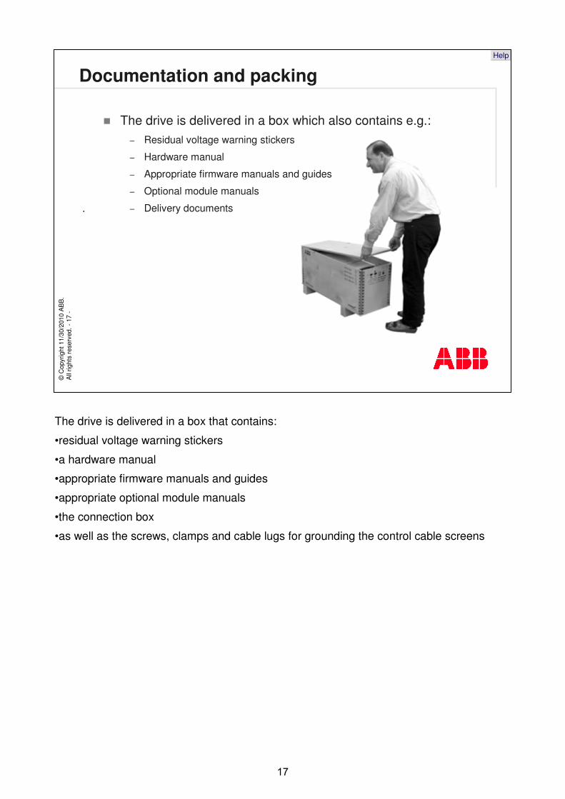
The drive is delivered in a box that contains:
•residual voltage warning stickers
•a hardware manual
•appropriate firmware manuals and guides
•appropriate optional module manuals
•the connection box
•as well as the screws, clamps and cable lugs for grounding the control cable screens
.
©C
opyr
ight
11/
30/2
010
AB
B.
All
right
s re
serv
ed. -
18-
Help
Options
� Inbuilt options– EMC filter for 1st environment, category C2 according to EN 61800-3
(2004)
– EMC filter for 2nd environment, category C3 according to EN 61800-3 (2004)
– Analog and digital I/O extension modules
– Fieldbus modules
– Speed feedback modules
� External options– dU/dt and sine output filters
– Ethernet module NETA-01 for remote monitoring and diagnostics
� Other options– Control solutions
The built-in options of the ACS800-11 include EMC filters for the 1st and the 2nd environments, extension modules for additional I/O, fieldbus and speed feedback interface.
The external options include a dU/dt and sine output filters, and an Ethernet module NETA-01 for remote monitoring and diagnostics.
Software options are officially called control solutions and they are dedicated for different applications.
©C
opyr
ight
11/
30/2
010
AB
B.
All
right
s re
serv
ed. -
19-
Help
Availability
� Make-to-order product
� Electronic ordering possible and recommended
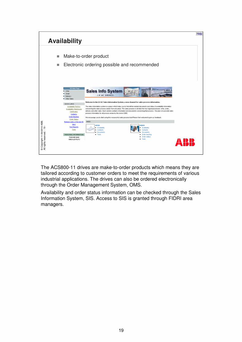
The ACS800-11 drives are make-to-order products which means they are tailored according to customer orders to meet the requirements of various industrial applications. The drives can also be ordered electronically through the Order Management System, OMS.
Availability and order status information can be checked through the Sales Information System, SIS. Access to SIS is granted through FIDRI area managers.
©C
opyr
ight
11/
30/2
010
AB
B.
All
right
s re
serv
ed. -
20-
Help
Installation
� Wall mounting � Cabinet installation
Air baffle plates
Main air flow out
Main air flow in
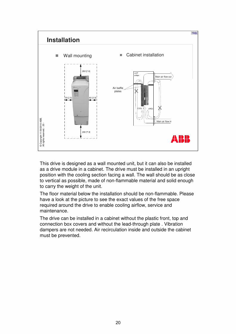
This drive is designed as a wall mounted unit, but it can also be installed as a drive module in a cabinet. The drive must be installed in an upright position with the cooling section facing a wall. The wall should be as close to vertical as possible, made of non-flammable material and solid enough to carry the weight of the unit.
The floor material below the installation should be non-flammable. Please have a look at the picture to see the exact values of the free space required around the drive to enable cooling airflow, service andmaintenance.
The drive can be installed in a cabinet without the plastic front, top and connection box covers and without the lead-through plate . Vibration dampers are not needed. Air recirculation inside and outside the cabinet must be prevented.
©C
opyr
ight
11/
30/2
010
AB
B.
All
right
s re
serv
ed. -
21-
Help
Commissioning
� ACS800-11 can be commissioned with– Control panel with the start-up assistant
– DriveWindow
� Start-up assistant guides the user through the parameter setting procedure
The drive can be commissioned using either the control panel or DriveWindow. Control panel has the start-up assistant that guides the user through all essential settings, without going directly into the parameter list.
©C
opyr
ight
11/
30/2
010
AB
B.
All
right
s re
serv
ed. -
22-
Help
Use
� Designed for any industrial application with braking requirements
� Has low harmonic distortion to supply network
� Provides high-performance and high overload capacity
� Can be configured according to need
The ACS800-11 and its current ratings are designed for any industrial application, especially for those requiring low harmonics at the supply network. The drive creates very little harmonic distortion on the supply network. High-performance and high overload capacity are available as in all ACS800 drives. This highly flexible drive can be configured to meet the precise needs of an application.
©C
opyr
ight
11/
30/2
010
AB
B.
All
right
s re
serv
ed. -
23-
Help
Maintenance
� Very little maintenance required
� The following routine maintenance intervals are recommended
Maintenance Interval
Capacitor reforming Every year when stored
Heatsink temperature check and cleaning
Depends on the dustiness of the environment (every 6 to 12 months)
Change of additional cooling fan Every three years
Main cooling fan change Every six years
Capacitors change Every ten years
If installed in an appropriate environment, the drive requires very little maintenance.
ABB recommends the following routine maintenance intervals:
•The capacitors should be reformed every year and changed every ten years.
•The heatsinks should be cleaned and its temperature checked, depending on the cleanliness of the environment, every 6 or 12 months.
•The cooling fans should be replaced every six years.
•Additional cooling fan should be changed every three years.
•For any additional information, see the hardware manual.
©C
opyr
ight
11/
30/2
010
AB
B.
All
right
s re
serv
ed. -
24-
Help
Services
� Global service network
� Productized services via lifecycle management model
� Start-up services by trained professionals
� Training services for the customer’s operating and service personnel
� Maintenance schedules and preventive maintenance kits
Global spare part, maintenance and repair services are provided by ABB’s own service personnel and by the personnel of ABB channel partners all over the world. ABB’s drive lifecycle management model is comprised of a palette of dedicated services for the entire lifecycle of the drive.
ABB global service network personnel are authorized professionals who are thoroughly trained for their job. The drives are correctly commissioned and tuned to their application. Dedicated training helps with the customer service and operating personnel acquire the required skills to use the drives correctly and safely. Maintenance schedules and preventive maintenance kits provide a systematic and functional means for maintaining the drives.
©C
opyr
ight
11/
30/2
010
AB
B.
All
right
s re
serv
ed. -
25-
Help
Summary
� Available for a wide range of industrial applications requiring high performance and high overload capacity
� Complete wall-mounted drives – can be installed without any additional cabinet or enclosure
� Highly programmable - can easily be adapted to different applications
� Important features and options built in
Key points of this module
ACS800-11 drives are designed for a wide range of industrial applications requiring braking capability, high performance and high overload capacity. They are complete wall-mounted drives and can be installed without any additional cabinet or enclosure.
They are also highly programmable and can easily be adapted to different applications. Important features and options are built-in.
©C
opyr
ight
11/
30/2
010
AB
B.
All
right
s re
serv
ed. -
26-
Help
Additional information
� ACS800, single drives, Technical catalogue
� ACS800-11 User’s Manual
� ACS800 configurator– login as a guest
Here are a few links to related information and additional references.
©C
opyr
ight
11/
30/2
010
AB
B.
All
right
s re
serv
ed. -
27-
Help
Glossary
� InbuiltIncluded in the basic hardware inside the covers of the drive
� EMC, electromagnetic compatibilityAbility of electrical/electronic equipment to operate without problems within an electromagnetic environment and without disturbing or interfering with any other product or system within its locality
� 1st environment (public low-voltage network)Includes domestic premises and establishments directly connected without intermediate transformer to a low-voltage power supply network which supplies buildings used for domestic purposes
� 2nd environment (industrial network)Includes all establishments other than those directly connected to a low-voltage power supply network which supplies buildings used for domestic purposes
� Plug-in modulesModules which are mounted directly to a drive interface by plugging them into a connector or terminal without tools
Here is a list of terms used in this module:
Thank you for viewing this module. You may now go ahead and move on to the next unit.