Embed Size (px)
Citation preview

ACQUITY UPLC H-ClassQuaternary Solvent Manager Operator’s Overview and Maintenance Information
Revision B
Copyright © Waters Corporation 2010All rights reserved
ii
Copyright notice
© 2010 WATERS CORPORATION. PRINTED IN THE UNITED STATES OF AMERICA AND IN IRELAND. ALL RIGHTS RESERVED. THIS DOCUMENT OR PARTS THEREOF MAY NOT BE REPRODUCED IN ANY FORM WITHOUT THE WRITTEN PERMISSION OF THE PUBLISHER.The information in this document is subject to change without notice and should not be construed as a commitment by Waters Corporation. Waters Corporation assumes no responsibility for any errors that may appear in this document. This document is believed to be complete and accurate at the time of publication. In no event shall Waters Corporation be liable for incidental or consequential damages in connection with, or arising from, its use.
Table of Contents
Copyright notice ................................................................................................... ii
Overview ................................................................................................................ 1 Features............................................................................................................. 1 Pressure flow envelope ........................................................................................ 1 Location of quaternary solvent manager in the ACQUITY UPLC H-Class
system............................................................................................................. 2 Major components................................................................................................ 3 Flow path through the solvent management system......................................... 6
Preparing for operation ..................................................................................... 7 Installing the leak sensor .................................................................................... 8 Installing the waste and degasser vent tubing ................................................ 11 Priming the seal wash system .......................................................................... 13 Priming the quaternary solvent manager ........................................................ 15 Washing the plungers........................................................................................ 19
Using the quaternary solvent manager ........................................................ 20 Vacuum degasser overview ............................................................................... 20 Installation recommendations for fittings........................................................ 21 Resolving leak sensor errors ............................................................................. 23
Maintaining the quaternary solvent manager ............................................ 28 Contacting Waters technical service................................................................. 28 Maintenance schedule ....................................................................................... 30 Maintenance considerations.............................................................................. 31 Configuring maintenance warnings ................................................................. 32 Replacing the leak sensor.................................................................................. 32 Replacing the inlet manifold ............................................................................. 37 Replacing the i2Valve actuator ......................................................................... 40 Replacing the i2Valve cartridge ........................................................................ 50 Replacing the accumulator check-valve............................................................ 59 Replacing solvent filters .................................................................................... 62 Cleaning the air filter in the quaternary solvent manager door..................... 63 Replacing the air filter in the quaternary solvent manager door ................... 64
Table of Contents iii
Removing the primary head and replacing its seals........................................ 65 Removing the accumulator head and replacing its seals ................................ 83 Replacing the primary head plunger ................................................................ 96 Replacing the accumulator head plunger....................................................... 116 Replacing the vent valve cartridge ................................................................. 131 Replacing the optional solvent selection valve cartridge............................... 134 Replacing the low-pressure inlet filters on the GPV outlet........................... 136 Replacing the 100-μL mixer/filter ................................................................... 138 Installing or replacing the optional 250-μL mixer/filter................................ 139 Cleaning the device’s exterior ......................................................................... 140
iv Table of Contents

Overview
The quaternary solvent manager (QSM) is a high-pressure pump that can simultaneously pump four degassed solvents (A, B, C, and D) through the ACQUITY UPLC® H-Class system. The pump can deliver gradients in eleven curve shapes (linear, two step, four convex, and four concave). When the optional solvent selection valve is installed, it is plumbed to solvent channel D, enabling solvent selections D1 through D6 in addition to A, B, and C (a total of nine solvents to select from).
Features• A gradient proportioning valve (GPV), to dynamically blend solvents in
any specified combination. The GPV produces predictable gradient segments regardless of solvent compressibility and system backpressure. Solvent selection and proportioning occur on the low-pressure (intake) side of the solvent delivery system, and solvents continue to blend under high pressure in each piston chamber.
• An integrated degasser that operates up to the maximum flow rate, with an independent channel for each solvent and an additional channel to accommodate the sample manager - flow through needle (SM-FTN) purge solvent.
• An automatic, programmable, seal wash. The pump's Wash Plungers function prevents the build-up of precipitates on the pump plungers by washing them with seal wash solvent at user-specified intervals.
• An electronically controlled Intelligent Intake Valve (i2Valve), to speed system priming and reduce startup times. The i2Valve minimizes solvent flow disturbances in the inlet lines by closely synchronizing the valve performance with pump operation.
• A vent valve that automatically switches to waste for priming and rapid solvent changeover.
Pressure flow envelopeThe QSM, a single pump with a proportioning valve, has a maximum operating pressure of 103,421 kPa (1034 bar, 15,000 psi) at flow rates up to 1 mL/min that decreases linearly to 62,053 kPa (621 bar, 9000 psi) at flow rates up to 2 mL/min.
Overview 1
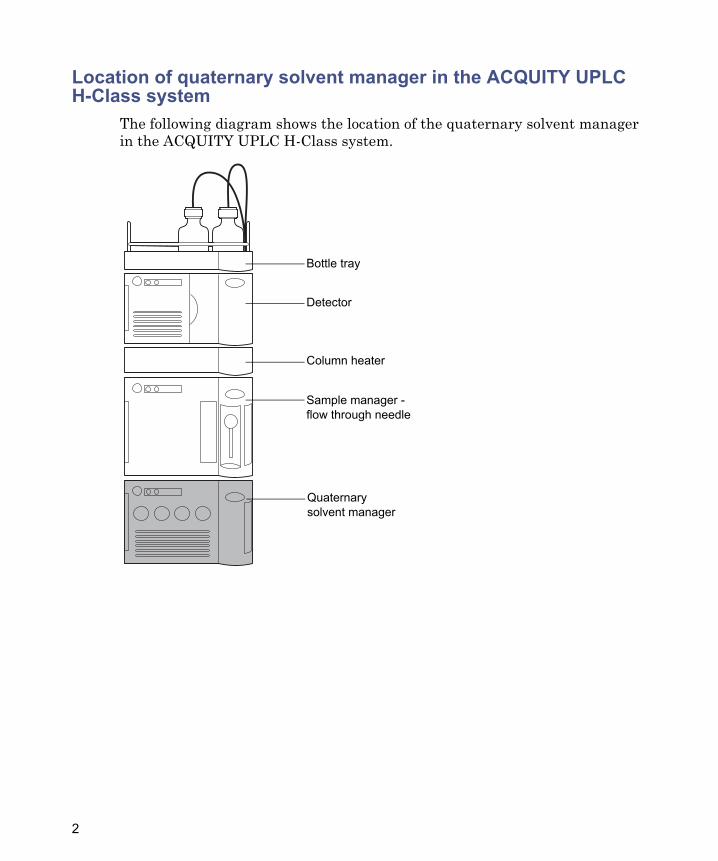
Location of quaternary solvent manager in the ACQUITY UPLC H-Class system
The following diagram shows the location of the quaternary solvent manager in the ACQUITY UPLC H-Class system.
Bottle tray
Detector
Column heater
Sample manager - flow through needle
Quaternary solvent manager
2
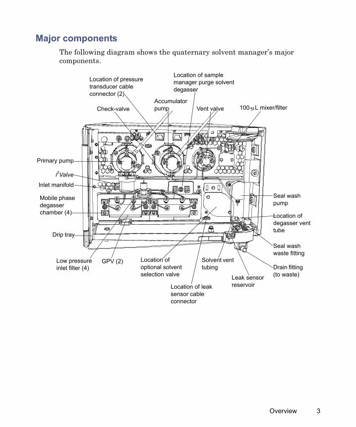
Major componentsThe following diagram shows the quaternary solvent manager’s major components.
Primary pump
Vent valveAccumulator pump
Drain fitting (to waste)
Inlet manifold
Leak sensor reservoir
Location of pressure transducer cable connector (2)
Seal wash pump
i2Valve
Drip tray
Low pressure inlet filter (4)
GPV (2)
Mobile phase degasser chamber (4)
100-μL mixer/filter
Location of degasser vent tube
Check-valve
Seal wash waste fitting
Location of sample manager purge solvent degasser
Location of leak sensor cable connector
Solvent vent tubing
Location of optional solvent selection valve
Overview 3
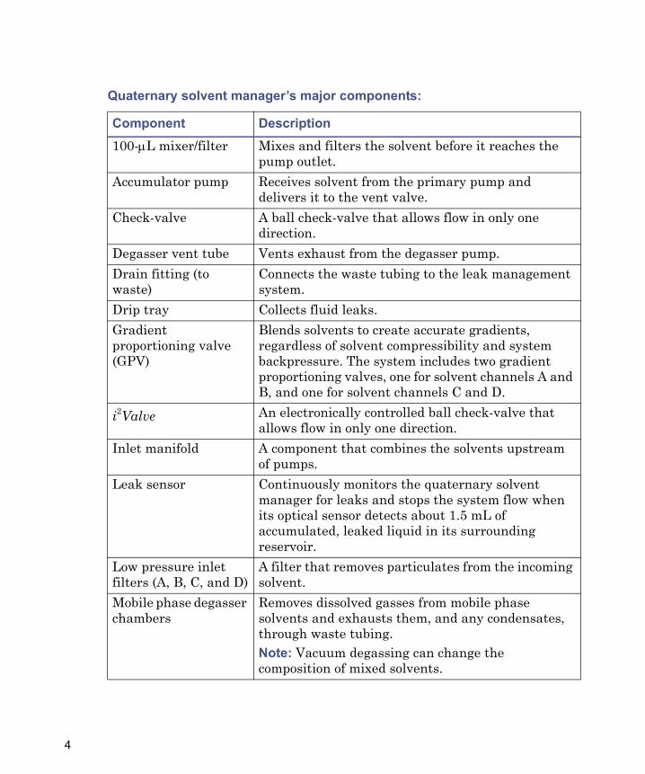
Quaternary solvent manager’s major components:
Component Description100-μL mixer/filter Mixes and filters the solvent before it reaches the
pump outlet.Accumulator pump Receives solvent from the primary pump and
delivers it to the vent valve.Check-valve A ball check-valve that allows flow in only one
direction.Degasser vent tube Vents exhaust from the degasser pump.Drain fitting (to waste)
Connects the waste tubing to the leak management system.
Drip tray Collects fluid leaks.Gradient proportioning valve (GPV)
Blends solvents to create accurate gradients, regardless of solvent compressibility and system backpressure. The system includes two gradient proportioning valves, one for solvent channels A and B, and one for solvent channels C and D.
i2Valve An electronically controlled ball check-valve that allows flow in only one direction.
Inlet manifold A component that combines the solvents upstream of pumps.
Leak sensor Continuously monitors the quaternary solvent manager for leaks and stops the system flow when its optical sensor detects about 1.5 mL of accumulated, leaked liquid in its surrounding reservoir.
Low pressure inlet filters (A, B, C, and D)
A filter that removes particulates from the incoming solvent.
Mobile phase degasser chambers
Removes dissolved gasses from mobile phase solvents and exhausts them, and any condensates, through waste tubing.Note: Vacuum degassing can change the composition of mixed solvents.
4
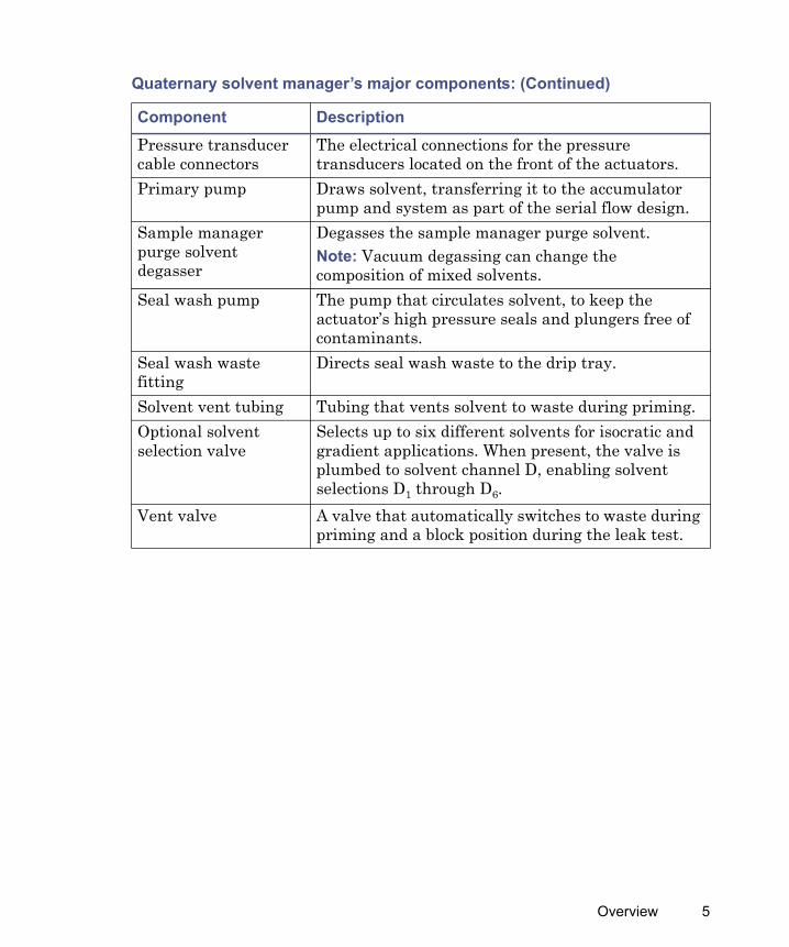
Pressure transducer cable connectors
The electrical connections for the pressure transducers located on the front of the actuators.
Primary pump Draws solvent, transferring it to the accumulator pump and system as part of the serial flow design.
Sample manager purge solvent degasser
Degasses the sample manager purge solvent.Note: Vacuum degassing can change the composition of mixed solvents.
Seal wash pump The pump that circulates solvent, to keep the actuator’s high pressure seals and plungers free of contaminants.
Seal wash waste fitting
Directs seal wash waste to the drip tray.
Solvent vent tubing Tubing that vents solvent to waste during priming.Optional solvent selection valve
Selects up to six different solvents for isocratic and gradient applications. When present, the valve is plumbed to solvent channel D, enabling solvent selections D1 through D6.
Vent valve A valve that automatically switches to waste during priming and a block position during the leak test.
Quaternary solvent manager’s major components: (Continued)
Component Description
Overview 5
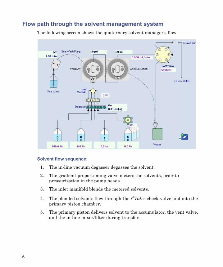
Flow path through the solvent management systemThe following screen shows the quaternary solvent manager’s flow.
Solvent flow sequence:
1. The in-line vacuum degasser degasses the solvent.
2. The gradient proportioning valve meters the solvents, prior to pressurization in the pump heads.
3. The inlet manifold blends the metered solvents.
4. The blended solvents flow through the i2Valve check-valve and into the primary piston chamber.
5. The primary piston delivers solvent to the accumulator, the vent valve, and the in-line mixer/filter during transfer.
6
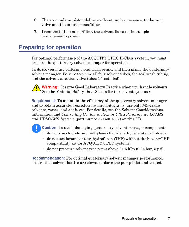
6. The accumulator piston delivers solvent, under pressure, to the vent valve and the in-line mixer/filter.
7. From the in-line mixer/filter, the solvent flows to the sample management system.
Preparing for operation
For optimal performance of the ACQUITY UPLC H-Class system, you must prepare the quaternary solvent manager for operation.To do so, you must perform a seal wash prime, and then prime the quaternary solvent manager. Be sure to prime all four solvent tubes, the seal wash tubing, and the solvent selection valve tubes (if installed).
Requirement: To maintain the efficiency of the quaternary solvent manager and to obtain accurate, reproducible chromatograms, use only MS-grade solvents, water, and additives. For details, see the Solvent Considerations information and Controlling Contamination in Ultra Performance LC/MS and HPLC/MS Systems (part number 715001307) on this CD.
Recommendation: For optimal quaternary solvent manager performance, ensure that solvent bottles are elevated above the pump inlet and vented.
Warning: Observe Good Laboratory Practice when you handle solvents. See the Material Safety Data Sheets for the solvents you use.
Caution: To avoid damaging quaternary solvent manager components• do not use chloroform, methylene chloride, ethyl acetate, or toluene.• do not use hexane or tetrahydrofuran (THF) without the hexane/THF
compatibility kit for ACQUITY UPLC systems.• do not pressure solvent reservoirs above 34.5 kPa (0.34 bar, 5 psi).
Preparing for operation 7
Installing the leak sensor
Required materials
• Gloves: clean, powder-free, chemical-resistant• Leak sensor
To install the leak sensor:
1. Power-off the quaternary solvent manager.
2. Open the quaternary solvent manager’s door, gently pulling its right-hand edge toward you.
Warning: To prevent injury, always observe Good Laboratory Practice when you handle solvents, change tubing, or operate the quaternary solvent manager. Consult the Material Safety Data Sheets regarding the solvents you use.
Warning: The leak sensor can be contaminated with biohazardous and/or toxic materials. Always wear clean, chemical-resistant, powder-free gloves when performing this procedure.
Caution: To avoid damaging electrical parts, never disconnect an electrical assembly while power is applied to an instrument or device. To completely interrupt power, set the power switch to Off, and then unplug the power cord from the AC source. Wait 10 seconds thereafter before you disconnect an assembly.
8
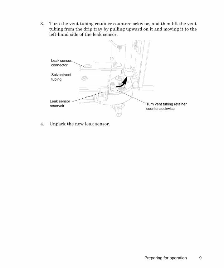
3. Turn the vent tubing retainer counterclockwise, and then lift the vent tubing from the drip tray by pulling upward on it and moving it to the left-hand side of the leak sensor.
4. Unpack the new leak sensor.
Turn vent tubing retainer counterclockwise
Solvent vent tubing
Leak sensor reservoir
Leak sensor connector
Preparing for operation 9
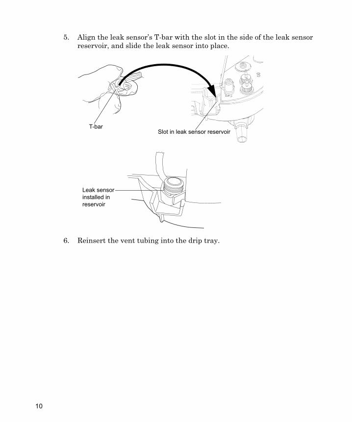
5. Align the leak sensor’s T-bar with the slot in the side of the leak sensor reservoir, and slide the leak sensor into place.
6. Reinsert the vent tubing into the drip tray.
TP02892
Slot in leak sensor reservoir
Leak sensor installed in reservoir
T-bar
10
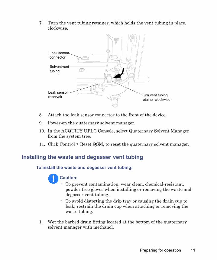
7. Turn the vent tubing retainer, which holds the vent tubing in place, clockwise.
8. Attach the leak sensor connector to the front of the device.
9. Power-on the quaternary solvent manager.
10. In the ACQUITY UPLC Console, select Quaternary Solvent Manager from the system tree.
11. Click Control > Reset QSM, to reset the quaternary solvent manager.
Installing the waste and degasser vent tubing
To install the waste and degasser vent tubing:
1. Wet the barbed drain fitting located at the bottom of the quaternary solvent manager with methanol.
Caution: • To prevent contamination, wear clean, chemical-resistant,
powder-free gloves when installing or removing the waste and degasser vent tubing.
• To avoid distorting the drip tray or causing the drain cup to leak, restrain the drain cup when attaching or removing the waste tubing.
Turn vent tubing retainer clockwise
Solvent vent tubing
Leak sensor reservoir
Leak sensor connector
Preparing for operation 11
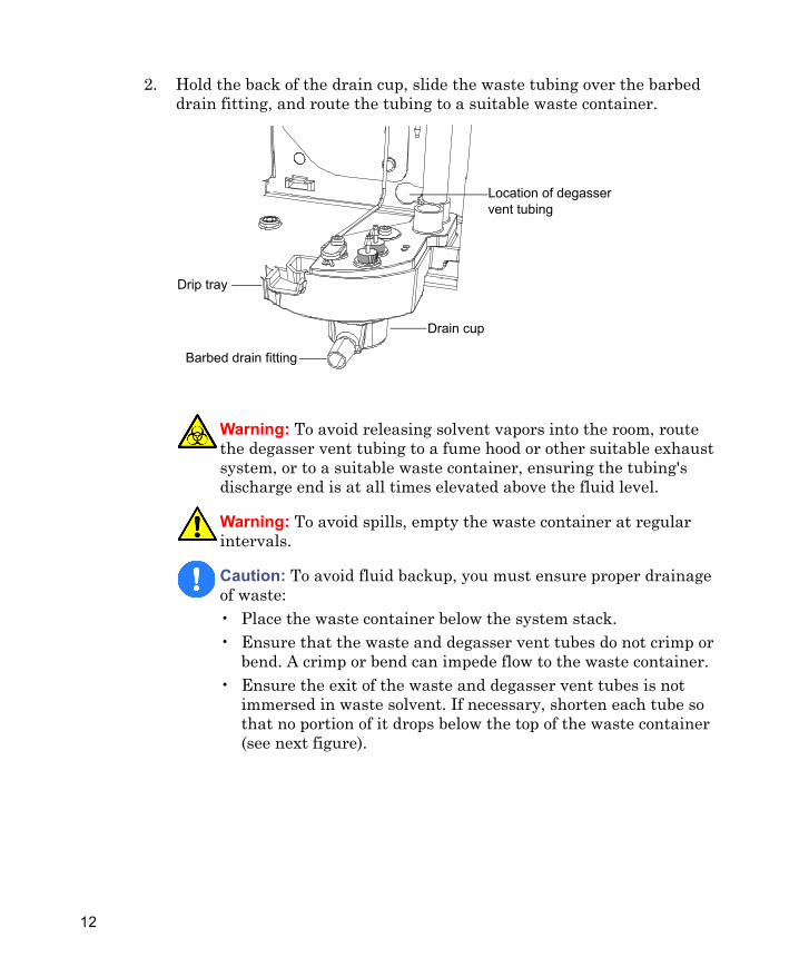
2. Hold the back of the drain cup, slide the waste tubing over the barbed drain fitting, and route the tubing to a suitable waste container.
Warning: To avoid releasing solvent vapors into the room, route the degasser vent tubing to a fume hood or other suitable exhaust system, or to a suitable waste container, ensuring the tubing's discharge end is at all times elevated above the fluid level.
Warning: To avoid spills, empty the waste container at regular intervals.
Caution: To avoid fluid backup, you must ensure proper drainage of waste:• Place the waste container below the system stack.• Ensure that the waste and degasser vent tubes do not crimp or
bend. A crimp or bend can impede flow to the waste container.• Ensure the exit of the waste and degasser vent tubes is not
immersed in waste solvent. If necessary, shorten each tube so that no portion of it drops below the top of the waste container (see next figure).
Barbed drain fitting
Drain cup
Drip tray
Location of degasser vent tubing
12
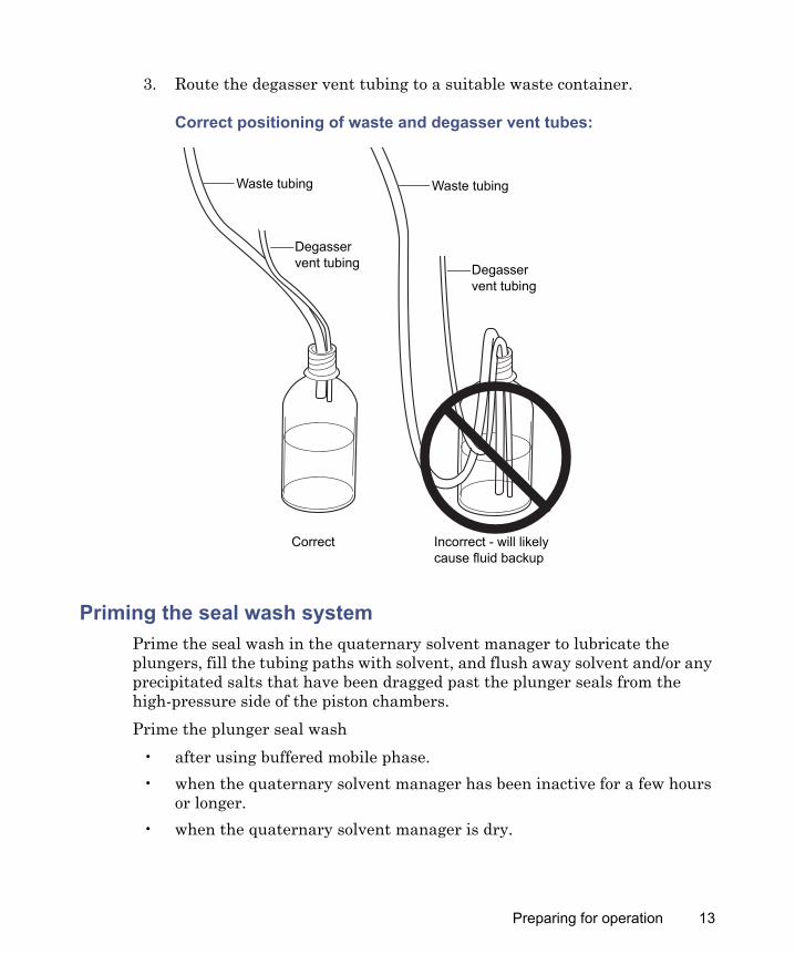
3. Route the degasser vent tubing to a suitable waste container.
Correct positioning of waste and degasser vent tubes:
Priming the seal wash systemPrime the seal wash in the quaternary solvent manager to lubricate the plungers, fill the tubing paths with solvent, and flush away solvent and/or any precipitated salts that have been dragged past the plunger seals from the high-pressure side of the piston chambers.Prime the plunger seal wash
• after using buffered mobile phase.• when the quaternary solvent manager has been inactive for a few hours
or longer.• when the quaternary solvent manager is dry.
TP02709
Waste tubing
Degasser vent tubing
Waste tubing
Degasser vent tubing
Correct Incorrect - will likely cause fluid backup
Preparing for operation 13
Tip: The seal wash is self-priming, but you can use a syringe to hasten the priming process.Recommendations:
• The composition of seal wash includes at least 10% organic solvent, a concentration that prevents microbial growth and ensures that the seal wash can solubilize the mobile phase.
• Before priming the plunger seals, ensure the volume of seal wash is adequate for priming.
See also: Controlling Contamination in Ultra Performance LC/MS and HPLC/MS Systems (part number 715001307) on the ACQUITY UPLC System Bookshelf CD.
Required materials
• 30-mL syringe (startup kit)• Seal wash solution• Tubing adapter (startup kit)
Caution: • To avoid damaging the solenoid valve seats and seals in the solvent
path, do not use a nonvolatile buffer as the seal wash solvent.• To avoid clogging system tubing, ensure the seal wash solvent is
100% compatible with the mobile phase conditions.• To prevent contamination, do not recycle seal wash.
14
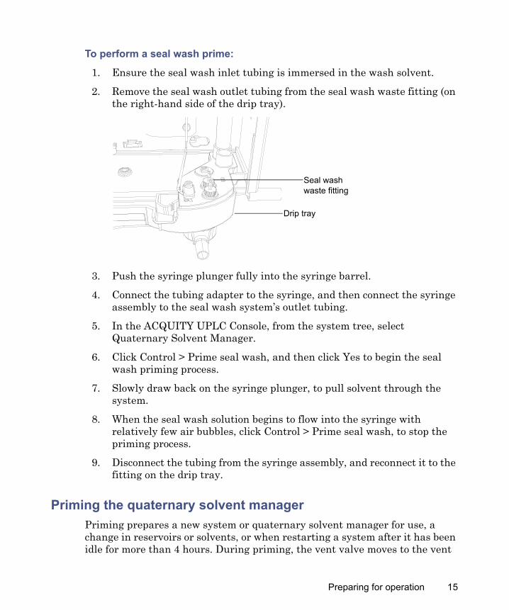
To perform a seal wash prime:
1. Ensure the seal wash inlet tubing is immersed in the wash solvent.
2. Remove the seal wash outlet tubing from the seal wash waste fitting (on the right-hand side of the drip tray).
3. Push the syringe plunger fully into the syringe barrel.
4. Connect the tubing adapter to the syringe, and then connect the syringe assembly to the seal wash system’s outlet tubing.
5. In the ACQUITY UPLC Console, from the system tree, select Quaternary Solvent Manager.
6. Click Control > Prime seal wash, and then click Yes to begin the seal wash priming process.
7. Slowly draw back on the syringe plunger, to pull solvent through the system.
8. When the seal wash solution begins to flow into the syringe with relatively few air bubbles, click Control > Prime seal wash, to stop the priming process.
9. Disconnect the tubing from the syringe assembly, and reconnect it to the fitting on the drip tray.
Priming the quaternary solvent managerPriming prepares a new system or quaternary solvent manager for use, a change in reservoirs or solvents, or when restarting a system after it has been idle for more than 4 hours. During priming, the vent valve moves to the vent
Drip tray
Seal wash waste fitting
Preparing for operation 15

position, ensuring minimal backpressure and directing the flow to waste. The flow rate during priming is 4 mL/min.Tip: If you are priming a dry quaternary solvent manager, using a syringe shortens the time required for priming.
Ensure the solvent reservoirs contain sufficient solvent for adequate priming and that the waste container can hold all the used solvent. For example, at 4 mL/min, priming for 5 minutes uses about 20 mL of each solvent.
Requirement: So that the degasser functions properly, prime all solvent lines with solvent.
Priming a dry quaternary solvent manager via the console
To prime the quaternary solvent manager:
1. Open the device’s front door.
2. Locate the appropriate solvent vent tubing.
3. In the ACQUITY UPLC Console, select Quaternary Solvent Manager from the system tree.
4. In the quaternary solvent manager information window, click Control > Prime solvents.
5. In the Prime Solvents dialog box, select solvent A, B, C, D, or (instead of D) D1 through D6.
6. In the Time box, specify the number of minutes from 0.1 through 60.0.Default: 2.0 minutes
Caution: To prevent salts from precipitating in the system, introduce an intermediate solvent, such as water, when changing from buffers to high-organic-content solvents. Be sure to consult the solvent miscibility tables in the Solvent Considerations section.
Warning: To avoid spills, empty the waste container at regular intervals.
16
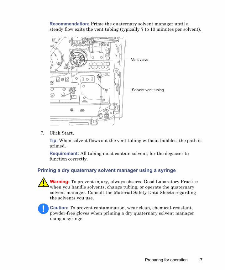
Recommendation: Prime the quaternary solvent manager until a steady flow exits the vent tubing (typically 7 to 10 minutes per solvent).
7. Click Start.Tip: When solvent flows out the vent tubing without bubbles, the path is primed.Requirement: All tubing must contain solvent, for the degasser to function correctly.
Priming a dry quaternary solvent manager using a syringe
Warning: To prevent injury, always observe Good Laboratory Practice when you handle solvents, change tubing, or operate the quaternary solvent manager. Consult the Material Safety Data Sheets regarding the solvents you use.
Caution: To prevent contamination, wear clean, chemical-resistant, powder-free gloves when priming a dry quaternary solvent manager using a syringe.
Solvent vent tubing
Vent valve
Preparing for operation 17
Required materials
• 30-mL syringe (startup kit)• Gloves: clean, powder-free, chemical-resistant• Seal wash solution• Tubing adapter (startup kit)
To prime a dry quaternary solvent manager:
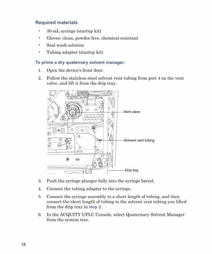
1. Open the device’s front door.
2. Follow the stainless steel solvent vent tubing from port 4 on the vent valve, and lift it from the drip tray.
3. Push the syringe plunger fully into the syringe barrel.
4. Connect the tubing adapter to the syringe.
5. Connect the syringe assembly to a short length of tubing, and then connect the short length of tubing to the solvent vent tubing you lifted from the drip tray in step 2.
6. In the ACQUITY UPLC Console, select Quaternary Solvent Manager from the system tree.
Solvent vent tubing
Vent valve
Drip tray
18
7. In the quaternary solvent manager information window, click Control > Prime solvents.
8. In the Prime Solvents dialog box, select the line you want to prime.
9. In the Time box, specify the number of minutes, from 0.1 through 60.0.Recommendation: The default setting is 2.0 minutes. Nevertheless, prime the quaternary solvent manager until a steady flow exits the vent tubing (typically 3 minutes).
10. Click Start.
11. Slowly withdraw the syringe plunger.Tip: When solvent flows out the vent tubing without bubbles, the path is primed.
12. Remove the syringe from the vent tubing, and reconnect the vent tubing to the drip tray.
13. Repeat step 2 through step 12 for the remaining solvents, including any solvent lines plumbed to the optional solvent selection valve.Requirement: All tubing must contain solvent for the degasser to function correctly.
Washing the plungersThe plunger wash function washes the plungers with seal wash solvent. It is designed to prevent the build-up of precipitates on the pump plungers, which can cause damage to the high-pressure seals.The cycle starts by filling and then slowly emptying the primary and accumulator chambers with the current solvent composition while performing a high-speed and high-volume seal wash.Recommendation: Perform this procedure after using buffered solvents.In addition, the plunger wash routine runs when the solvent manager is idle. The seal wash solvent washes the plungers, moving them backward and
Preparing for operation 19
forward, so most of the surface is washed. The plunger wash routine continues for two minutes performing these operations:
• Starts the seal wash pump• Slowly empties and fills the syringes, with the vent valve set to waste,
thus moving the plungers through the seal wash flow.• Repeats the emptying and filling of syringes for a total of two cycles.
To wash the plungers:
In the console, select the solvent manager > Maintain > Wash plungers.
Using the quaternary solvent manager
Vacuum degasser overviewQuaternary solvent managers are equipped with an absolute pressure transducer (APT), which is unaffected by altitude or barometric changes. The following table lists the attributes of APT-equipped separations modules.
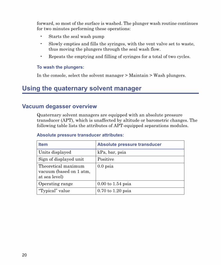
Absolute pressure transducer attributes:
Item Absolute pressure transducerUnits displayed kPa, bar, psiaSign of displayed unit PositiveTheoretical maximum vacuum (based on 1 atm, at sea level)
0.0 psia
Operating range 0.00 to 1.54 psia“Typical” value 0.70 to 1.20 psia
20
Installation recommendations for fittings
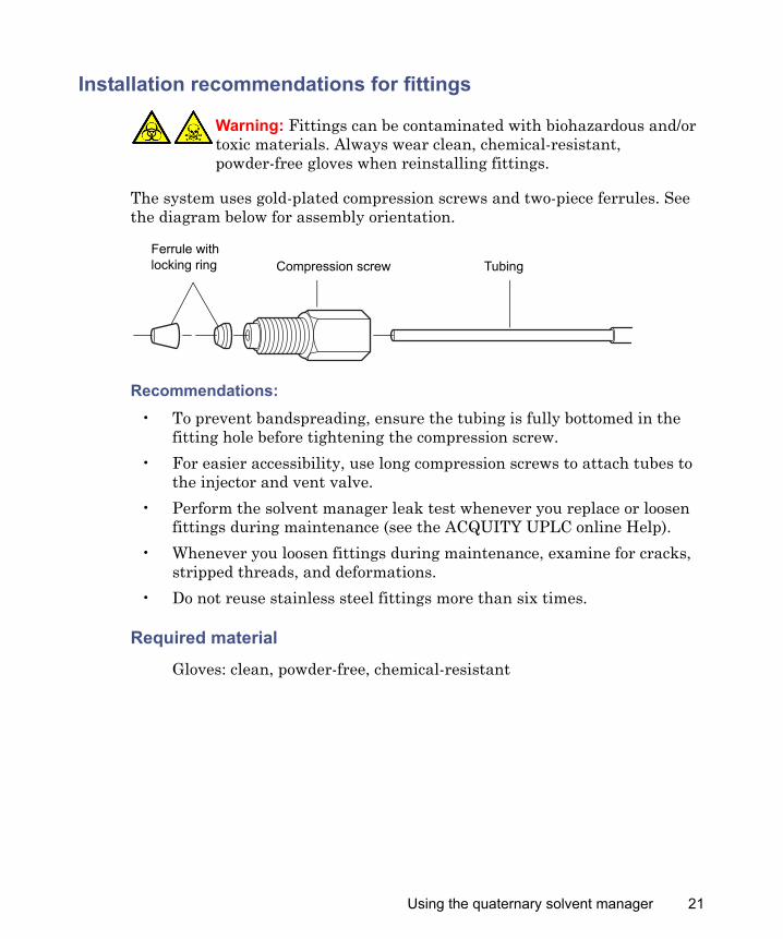
The system uses gold-plated compression screws and two-piece ferrules. See the diagram below for assembly orientation.
Recommendations:• To prevent bandspreading, ensure the tubing is fully bottomed in the
fitting hole before tightening the compression screw.• For easier accessibility, use long compression screws to attach tubes to
the injector and vent valve.• Perform the solvent manager leak test whenever you replace or loosen
fittings during maintenance (see the ACQUITY UPLC online Help).• Whenever you loosen fittings during maintenance, examine for cracks,
stripped threads, and deformations.• Do not reuse stainless steel fittings more than six times.
Required material
Gloves: clean, powder-free, chemical-resistant
Warning: Fittings can be contaminated with biohazardous and/or toxic materials. Always wear clean, chemical-resistant, powder-free gloves when reinstalling fittings.
TubingCompression screwFerrule with locking ring
Using the quaternary solvent manager 21
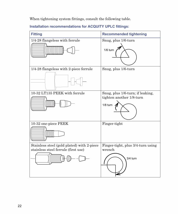
When tightening system fittings, consult the following table.
Installation recommendations for ACQUITY UPLC fittings:
Fitting Recommended tightening1/4-28 flangeless with ferrule Snug, plus 1/6-turn
1/4-28 flangeless with 2-piece ferrule Snug, plus 1/6-turn
10-32 LT135 PEEK with ferrule Snug, plus 1/6-turn; if leaking, tighten another 1/8-turn
10-32 one-piece PEEK Finger-tight
Stainless steel (gold plated) with 2-piece stainless steel ferrule (first use)
Finger-tight, plus 3/4-turn using wrench
1/6 turn
1/8 turn
3/4 turn
22
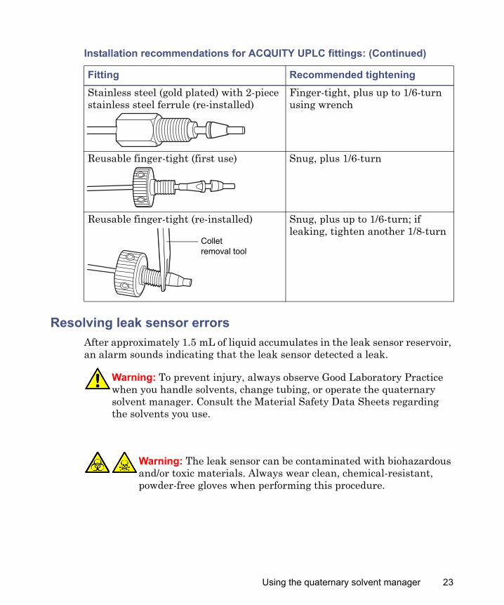
Resolving leak sensor errorsAfter approximately 1.5 mL of liquid accumulates in the leak sensor reservoir, an alarm sounds indicating that the leak sensor detected a leak.
Stainless steel (gold plated) with 2-piece stainless steel ferrule (re-installed)
Finger-tight, plus up to 1/6-turn using wrench
Reusable finger-tight (first use) Snug, plus 1/6-turn
Reusable finger-tight (re-installed) Snug, plus up to 1/6-turn; if leaking, tighten another 1/8-turn
Warning: To prevent injury, always observe Good Laboratory Practice when you handle solvents, change tubing, or operate the quaternary solvent manager. Consult the Material Safety Data Sheets regarding the solvents you use.
Warning: The leak sensor can be contaminated with biohazardous and/or toxic materials. Always wear clean, chemical-resistant, powder-free gloves when performing this procedure.
Installation recommendations for ACQUITY UPLC fittings: (Continued)
Fitting Recommended tightening
TP02728
Collet removal tool
Using the quaternary solvent manager 23
Required materials
• Cotton swabs• Gloves: clean, powder-free, chemical-resistant• Nonabrasive, lint-free wipes
To resolve a leak sensor error:
1. In the ACQUITY UPLC Console’s Leak Sensors dialog box, confirm that the quaternary solvent manager leak sensor detected a leak.Tip: When a leak is detected, a “Leak Detected” error message appears.
2. Power-off the quaternary solvent manager.
3. Open the quaternary solvent manager’s door, gently pulling its right-hand edge toward you.
4. Locate the source of the leak, and make the repairs necessary to stop the leak.
Caution: To avoid scratching or damaging the leak sensor• do not allow buffered solvents to accumulate and dry on it.• do not submerge it in a cleaning bath.
Caution: To avoid damaging electrical parts, never disconnect an electrical assembly while power is applied to an instrument or device. To completely interrupt power, set the power switch to Off, and then unplug the power cord from the AC source. Wait 10 seconds thereafter before you disconnect an assembly.
24
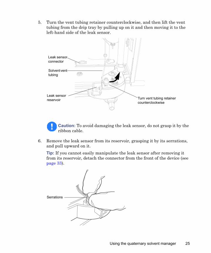
5. Turn the vent tubing retainer counterclockwise, and then lift the vent tubing from the drip tray by pulling up on it and then moving it to the left-hand side of the leak sensor.
6. Remove the leak sensor from its reservoir, grasping it by its serrations, and pull upward on it.Tip: If you cannot easily manipulate the leak sensor after removing it from its reservoir, detach the connector from the front of the device (see page 33).
Caution: To avoid damaging the leak sensor, do not grasp it by the ribbon cable.
Turn vent tubing retainer counterclockwise
Solvent vent tubing
Leak sensor reservoir
Leak sensor connector
Serrations
Using the quaternary solvent manager 25
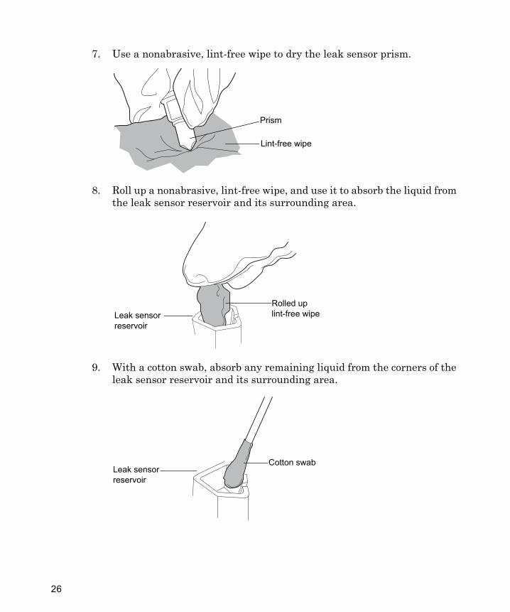
7. Use a nonabrasive, lint-free wipe to dry the leak sensor prism.
8. Roll up a nonabrasive, lint-free wipe, and use it to absorb the liquid from the leak sensor reservoir and its surrounding area.
9. With a cotton swab, absorb any remaining liquid from the corners of the leak sensor reservoir and its surrounding area.
TP02891
Prism
Lint-free wipe
Rolled up lint-free wipeLeak sensor
reservoir
Cotton swabLeak sensor reservoir
26
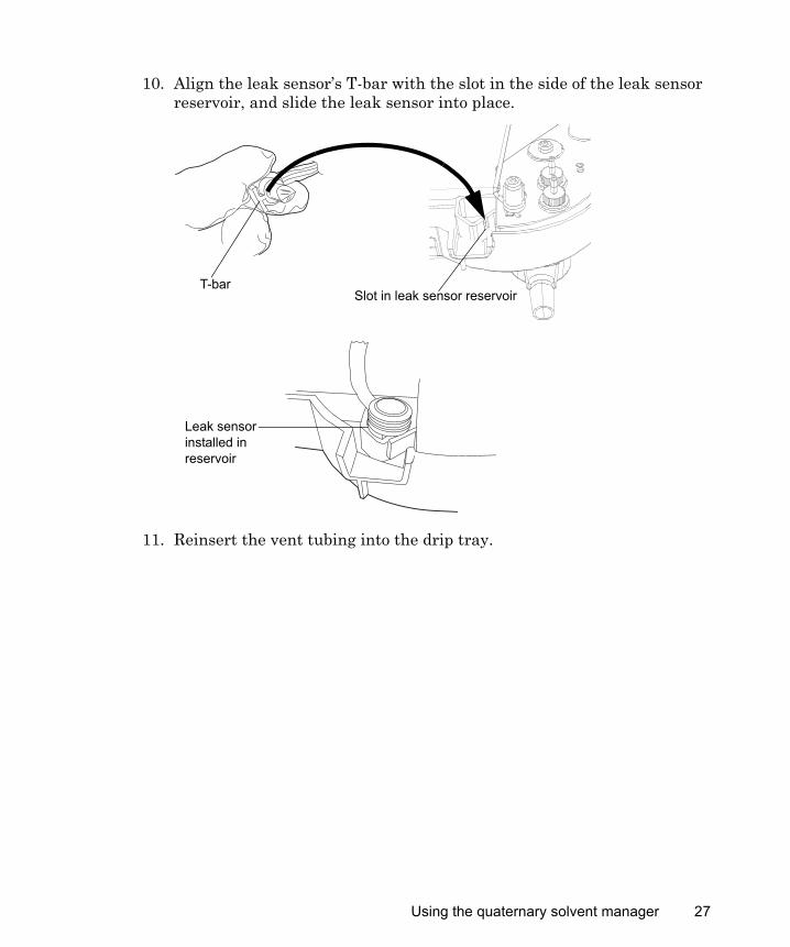
10. Align the leak sensor’s T-bar with the slot in the side of the leak sensor reservoir, and slide the leak sensor into place.
11. Reinsert the vent tubing into the drip tray.
TP02892
Slot in leak sensor reservoir
Leak sensor installed in reservoir
T-bar
Using the quaternary solvent manager 27
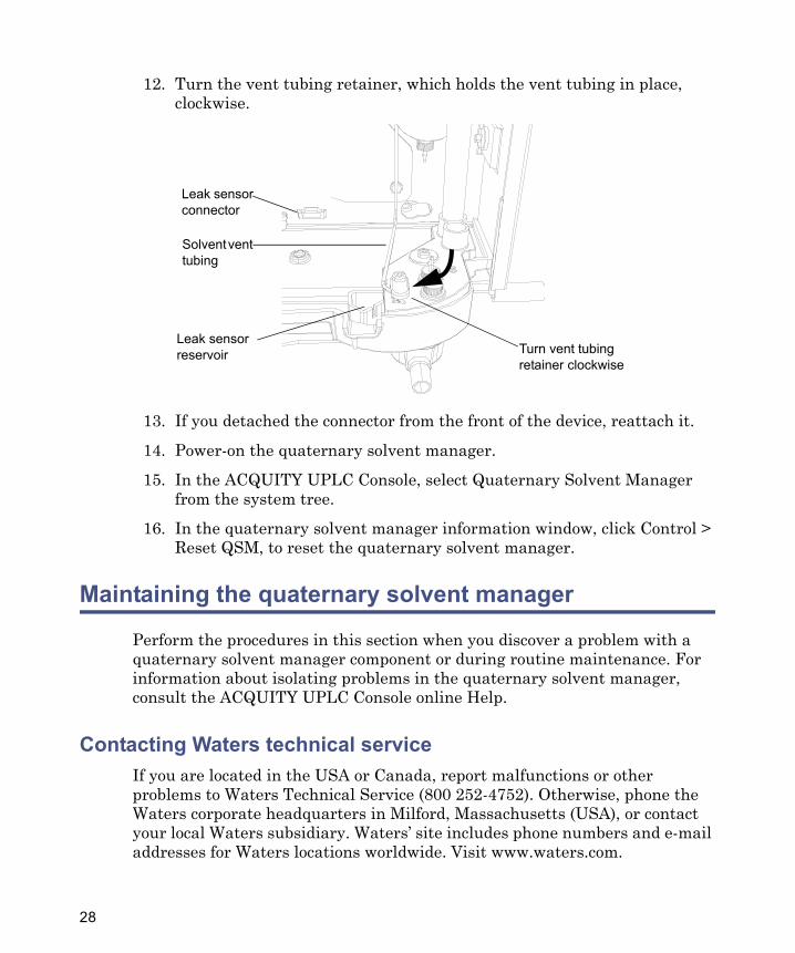
12. Turn the vent tubing retainer, which holds the vent tubing in place, clockwise.
13. If you detached the connector from the front of the device, reattach it.
14. Power-on the quaternary solvent manager.
15. In the ACQUITY UPLC Console, select Quaternary Solvent Manager from the system tree.
16. In the quaternary solvent manager information window, click Control > Reset QSM, to reset the quaternary solvent manager.
Maintaining the quaternary solvent manager
Perform the procedures in this section when you discover a problem with a quaternary solvent manager component or during routine maintenance. For information about isolating problems in the quaternary solvent manager, consult the ACQUITY UPLC Console online Help.
Contacting Waters technical serviceIf you are located in the USA or Canada, report malfunctions or other problems to Waters Technical Service (800 252-4752). Otherwise, phone the Waters corporate headquarters in Milford, Massachusetts (USA), or contact your local Waters subsidiary. Waters’ site includes phone numbers and e-mail addresses for Waters locations worldwide. Visit www.waters.com.
Turn vent tubing retainer clockwise
Solvent vent tubing
Leak sensor reservoir
Leak sensor connector
28
When you contact Waters, be prepared to provide this information:• Error message (if any)• Nature of the symptom• Instrument serial numbers and firmware version• Flow rate• Operating pressure• Solvent(s)• Detector settings (sensitivity and wavelength)• Type and serial number of column(s)• Sample type and diluent• Data software version and serial number• ACQUITY UPLC H-Class system workstation model and operating
system versionFor complete information on reporting shipping damages and submitting claims, see the document Waters Licenses, Warranties, and Support Services.
Locating system serial numbers
The serial number on the system’s instruments and devices facilitates service and support. Serial numbers also provide a way to create single log entries for each module so that you can review the usage history of only that instrument or device.Be prepared to provide the serial numbers of the instruments or devices in your system when you contact Waters customer support.
To view the information for an instrument or device:
1. In the ACQUITY UPLC Console, select an instrument or device from the system tree.
2. Click Configure > View module information.Result: The Module Information dialog box displays this information:• Serial number• Firmware version
Maintaining the quaternary solvent manager 29
• Firmware checksum• Component software version
Alternatives:• From the main window, place the pointer over the visual representation
of the system instrument or device you want information for.• Obtain the serial number from the printed labels on the rear panels of
instruments and devices or inside their front doors.
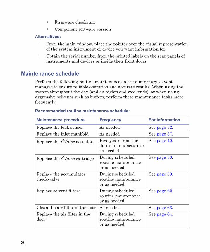
Maintenance schedulePerform the following routine maintenance on the quaternary solvent manager to ensure reliable operation and accurate results. When using the system throughout the day (and on nights and weekends), or when using aggressive solvents such as buffers, perform these maintenance tasks more frequently.
Recommended routine maintenance schedule:
Maintenance procedure Frequency For information...Replace the leak sensor As needed See page 32.Replace the inlet manifold As needed See page 37.
Replace the i2Valve actuator Five years from the date of manufacture or as needed
See page 40.
Replace the i2Valve cartridge During scheduled routine maintenance or as needed
See page 50.
Replace the accumulator check-valve
During scheduled routine maintenance or as needed
See page 59.
Replace solvent filters During scheduled routine maintenance or as needed
See page 62.
Clean the air filter in the door As needed See page 63.Replace the air filter in the door
During scheduled routine maintenance or as needed
See page 64.
30
Maintenance considerations
Safety and handling
Observe these warning and caution advisories when you perform maintenance operations on your system.
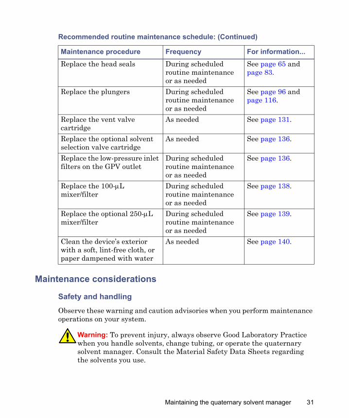
Replace the head seals During scheduled routine maintenance or as needed
See page 65 and page 83.
Replace the plungers During scheduled routine maintenance or as needed
See page 96 and page 116.
Replace the vent valve cartridge
As needed See page 131.
Replace the optional solvent selection valve cartridge
As needed See page 136.
Replace the low-pressure inlet filters on the GPV outlet
During scheduled routine maintenance or as needed
See page 136.
Replace the 100-μL mixer/filter
During scheduled routine maintenance or as needed
See page 138.
Replace the optional 250-μL mixer/filter
During scheduled routine maintenance or as needed
See page 139.
Clean the device’s exterior with a soft, lint-free cloth, or paper dampened with water
As needed See page 140.
Warning: To prevent injury, always observe Good Laboratory Practice when you handle solvents, change tubing, or operate the quaternary solvent manager. Consult the Material Safety Data Sheets regarding the solvents you use.
Recommended routine maintenance schedule: (Continued)
Maintenance procedure Frequency For information...
Maintaining the quaternary solvent manager 31
Proper operating procedures
To ensure a system runs efficiently, see “Preparing for operation” on page 7.
Configuring maintenance warningsMaintenance counters provide real-time usage status information that can help you determine when to schedule routine maintenance for specific components. You can set usage thresholds and maintenance warnings that alert you when a component reaches the designated threshold limit. By setting threshold limits and monitoring these usage counters regularly, you can minimize unexpected failures and unscheduled downtime during important work. For information on setting maintenance warnings, consult the ACQUITY UPLC Console online Help.
Replacing the leak sensor
Warning: To avoid electric shock, do not remove the device’s protective panels. The components within are not user-serviceable.
Caution: To avoid damaging electrical parts, never disconnect an electrical assembly while power is applied to an instrument or device. To completely interrupt power, set the power switch to Off, and then unplug the power cord from the AC source. Wait 10 seconds thereafter before you disconnect an assembly.
Warning: To prevent injury, always observe Good Laboratory Practice when you handle solvents, change tubing, or operate the quaternary solvent manager. Consult the Material Safety Data Sheets regarding the solvents you use.
Warning: The leak sensor can be contaminated with biohazardous and/or toxic materials. Always wear clean, chemical-resistant, powder-free gloves when performing this procedure.
32
Required materials
• Gloves: clean, powder-free, chemical-resistant• Leak sensor
To replace the leak sensor:
1. Power-off the quaternary solvent manager.
2. Open the quaternary solvent manager’s door, gently pulling its right-hand edge toward you.
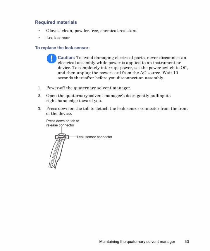
3. Press down on the tab to detach the leak sensor connector from the front of the device.
Caution: To avoid damaging electrical parts, never disconnect an electrical assembly while power is applied to an instrument or device. To completely interrupt power, set the power switch to Off, and then unplug the power cord from the AC source. Wait 10 seconds thereafter before you disconnect an assembly.
Leak sensor connector
Press down on tab to release connector
Maintaining the quaternary solvent manager 33
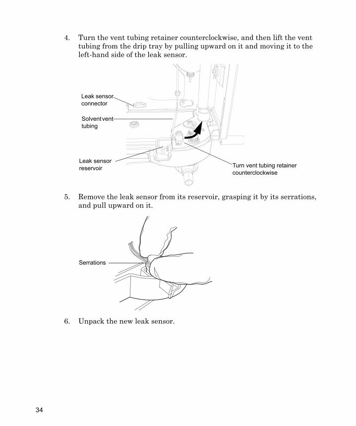
4. Turn the vent tubing retainer counterclockwise, and then lift the vent tubing from the drip tray by pulling upward on it and moving it to the left-hand side of the leak sensor.
5. Remove the leak sensor from its reservoir, grasping it by its serrations, and pull upward on it.
6. Unpack the new leak sensor.
Turn vent tubing retainer counterclockwise
Solvent vent tubing
Leak sensor reservoir
Leak sensor connector
Serrations
34
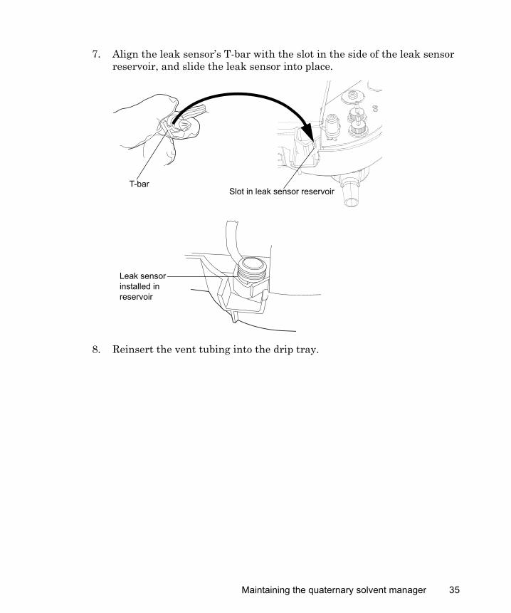
7. Align the leak sensor’s T-bar with the slot in the side of the leak sensor reservoir, and slide the leak sensor into place.
8. Reinsert the vent tubing into the drip tray.
TP02892
Slot in leak sensor reservoir
Leak sensor installed in reservoir
T-bar
Maintaining the quaternary solvent manager 35
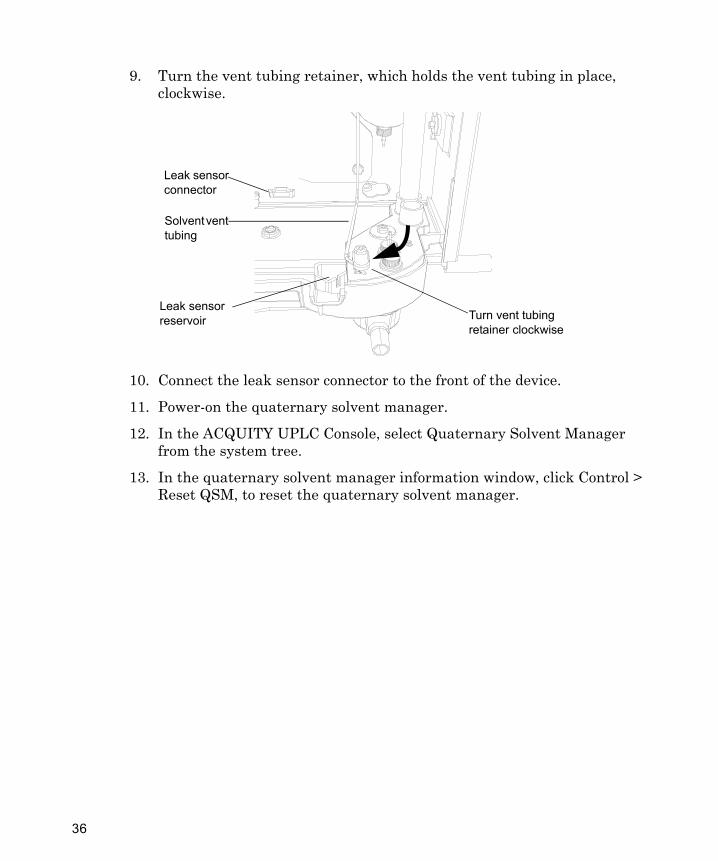
9. Turn the vent tubing retainer, which holds the vent tubing in place, clockwise.
10. Connect the leak sensor connector to the front of the device.
11. Power-on the quaternary solvent manager.
12. In the ACQUITY UPLC Console, select Quaternary Solvent Manager from the system tree.
13. In the quaternary solvent manager information window, click Control > Reset QSM, to reset the quaternary solvent manager.
Turn vent tubing retainer clockwise
Solvent vent tubing
Leak sensor reservoir
Leak sensor connector
36
Replacing the inlet manifold
Required materials
• 1/4-inch open-end wrench• Gloves: clean, powder-free, chemical-resistant• Inlet manifold
To replace the inlet manifold:
1. Power-off the quaternary solvent manager.
2. Open the quaternary solvent manager’s door, gently pulling its right-hand edge toward you.
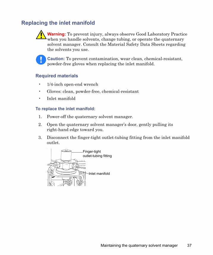
3. Disconnect the finger-tight outlet-tubing fitting from the inlet manifold outlet.
Warning: To prevent injury, always observe Good Laboratory Practice when you handle solvents, change tubing, or operate the quaternary solvent manager. Consult the Material Safety Data Sheets regarding the solvents you use.
Caution: To prevent contamination, wear clean, chemical-resistant, powder-free gloves when replacing the inlet manifold.
Inlet manifold
Finger-tight outlet-tubing fitting
Maintaining the quaternary solvent manager 37
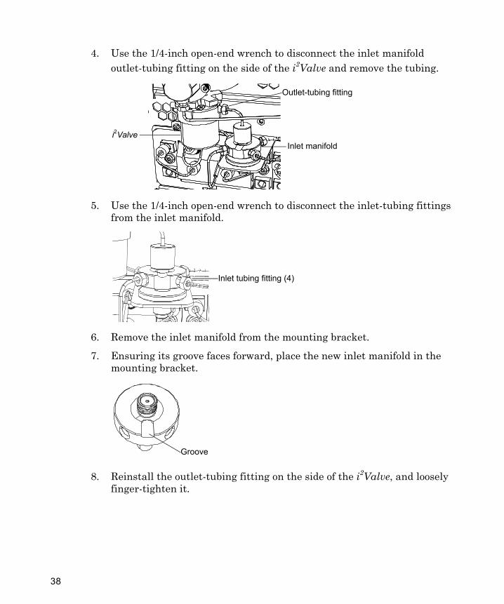
4. Use the 1/4-inch open-end wrench to disconnect the inlet manifold outlet-tubing fitting on the side of the i2Valve and remove the tubing.
5. Use the 1/4-inch open-end wrench to disconnect the inlet-tubing fittings from the inlet manifold.
6. Remove the inlet manifold from the mounting bracket.
7. Ensuring its groove faces forward, place the new inlet manifold in the mounting bracket.
8. Reinstall the outlet-tubing fitting on the side of the i2Valve, and loosely finger-tighten it.
Outlet-tubing fitting
Inlet manifoldi2Valve
Inlet tubing fitting (4)
Groove
38
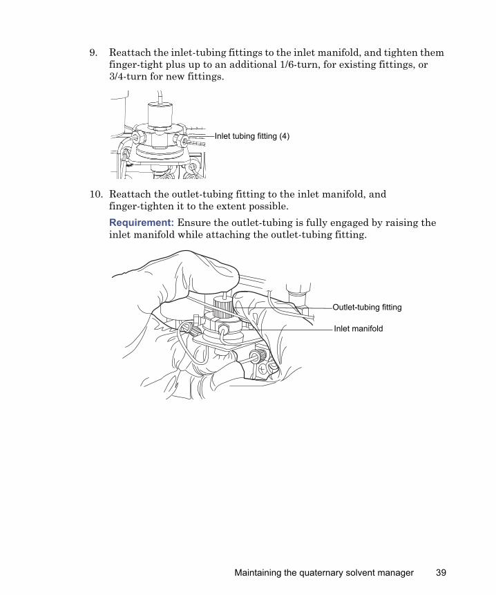
9. Reattach the inlet-tubing fittings to the inlet manifold, and tighten them finger-tight plus up to an additional 1/6-turn, for existing fittings, or 3/4-turn for new fittings.
10. Reattach the outlet-tubing fitting to the inlet manifold, and finger-tighten it to the extent possible.Requirement: Ensure the outlet-tubing is fully engaged by raising the inlet manifold while attaching the outlet-tubing fitting.
Inlet tubing fitting (4)
Outlet-tubing fitting
Inlet manifold
Maintaining the quaternary solvent manager 39
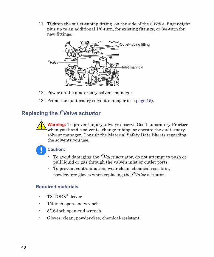
11. Tighten the outlet-tubing fitting, on the side of the i2Valve, finger-tight plus up to an additional 1/6-turn, for existing fittings, or 3/4-turn for new fittings.
12. Power-on the quaternary solvent manager.
13. Prime the quaternary solvent manager (see page 15).
Replacing the i2Valve actuator
Required materials
• T8 TORX® driver• 1/4-inch open-end wrench• 5/16-inch open-end wrench• Gloves: clean, powder-free, chemical-resistant
Warning: To prevent injury, always observe Good Laboratory Practice when you handle solvents, change tubing, or operate the quaternary solvent manager. Consult the Material Safety Data Sheets regarding the solvents you use.
Caution: • To avoid damaging the i2Valve actuator, do not attempt to push or
pull liquid or gas through the valve's inlet or outlet ports.• To prevent contamination, wear clean, chemical-resistant,
powder-free gloves when replacing the i2Valve actuator.
Outlet-tubing fitting
Inlet manifoldi2Valve
40
• i2Valve actuator
• i2Valve cartridge (recommended)
To replace the i2Valve actuator:
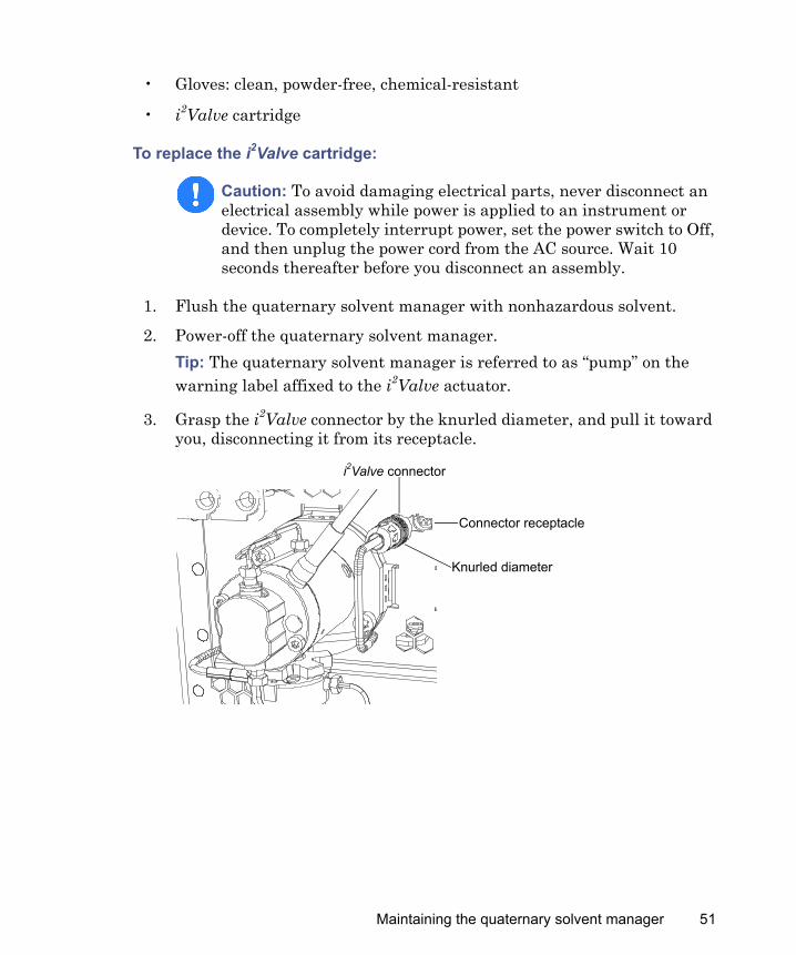
1. Flush the quaternary solvent manager with nonhazardous solvent.
2. Power-off the quaternary solvent manager.Tip: The quaternary solvent manager is referred to as “pump” on the warning label affixed to the i2Valve actuator.
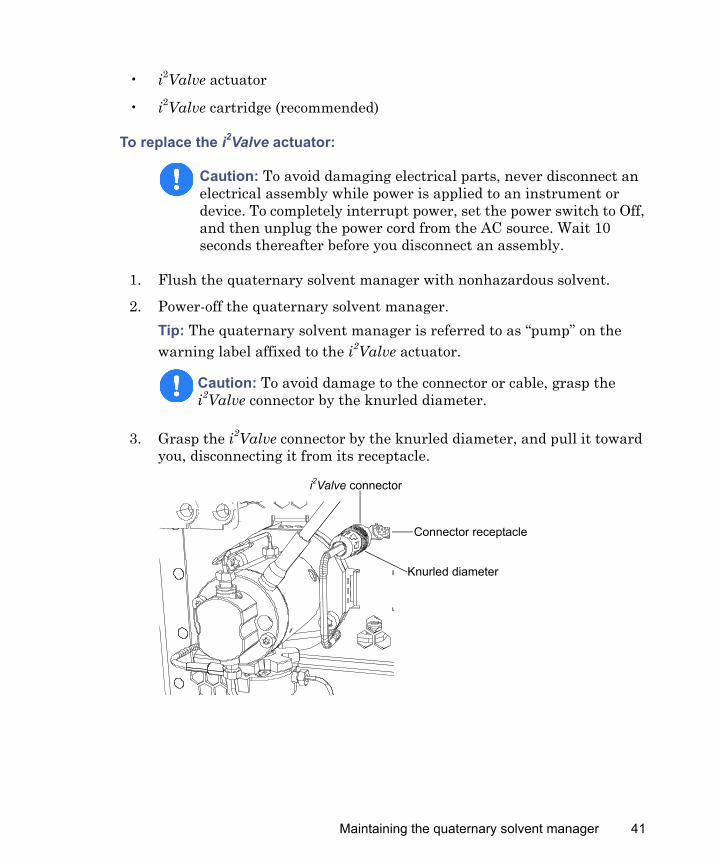
3. Grasp the i2Valve connector by the knurled diameter, and pull it toward you, disconnecting it from its receptacle.
Caution: To avoid damaging electrical parts, never disconnect an electrical assembly while power is applied to an instrument or device. To completely interrupt power, set the power switch to Off, and then unplug the power cord from the AC source. Wait 10 seconds thereafter before you disconnect an assembly.
Caution: To avoid damage to the connector or cable, grasp the i2Valve connector by the knurled diameter.
i2Valve connector
Knurled diameter
Connector receptacle
Maintaining the quaternary solvent manager 41

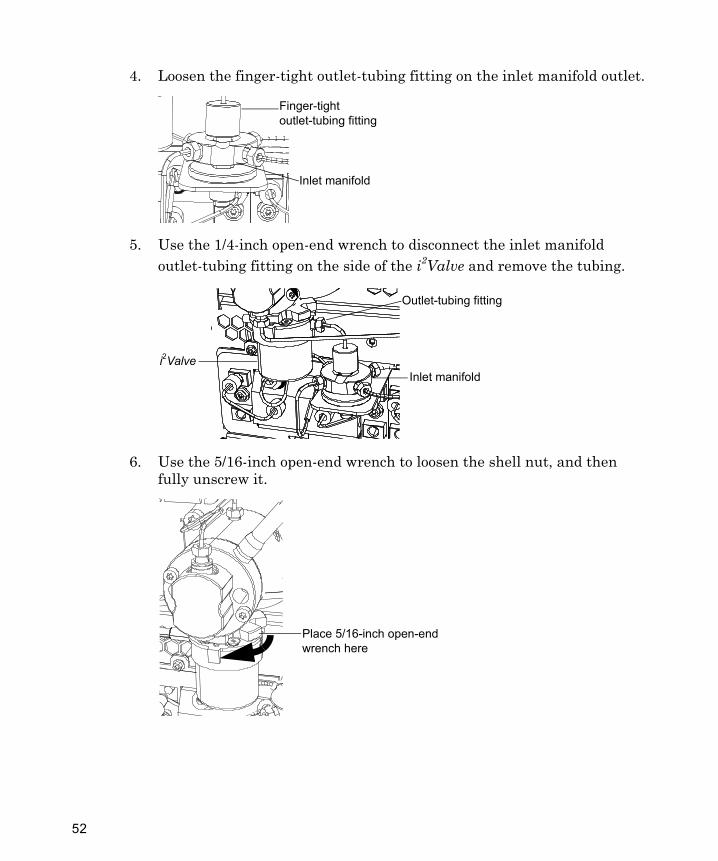
4. Loosen the finger-tight outlet-tubing fitting on the inlet manifold outlet.
5. Use the 1/4-inch open-end wrench to disconnect the inlet manifold outlet-tubing fitting on the side of the i2Valve and remove the tubing.
6. Use the 5/16-inch open-end wrench to loosen the shell nut, and then fully unscrew it.
Inlet manifold
Finger-tight outlet-tubing fitting
Outlet-tubing fitting
Inlet manifoldi2Valve
Place 5/16-inch open-end wrench here
42
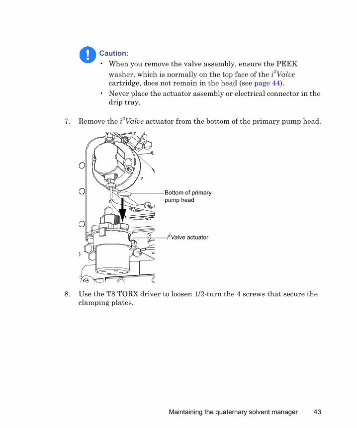
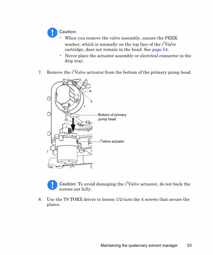
7. Remove the i2Valve actuator from the bottom of the primary pump head.
8. Use the T8 TORX driver to loosen 1/2-turn the 4 screws that secure the clamping plates.
Caution: • When you remove the valve assembly, ensure the PEEK
washer, which is normally on the top face of the i2Valve cartridge, does not remain in the head (see page 44).
• Never place the actuator assembly or electrical connector in the drip tray.
Bottom of primary pump head
i2Valve actuator
Maintaining the quaternary solvent manager 43
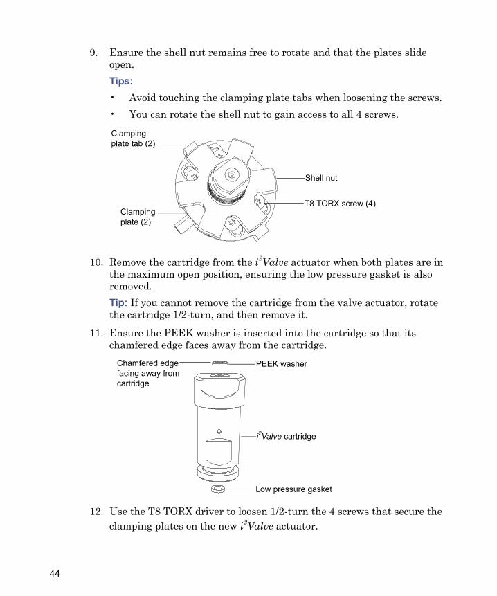
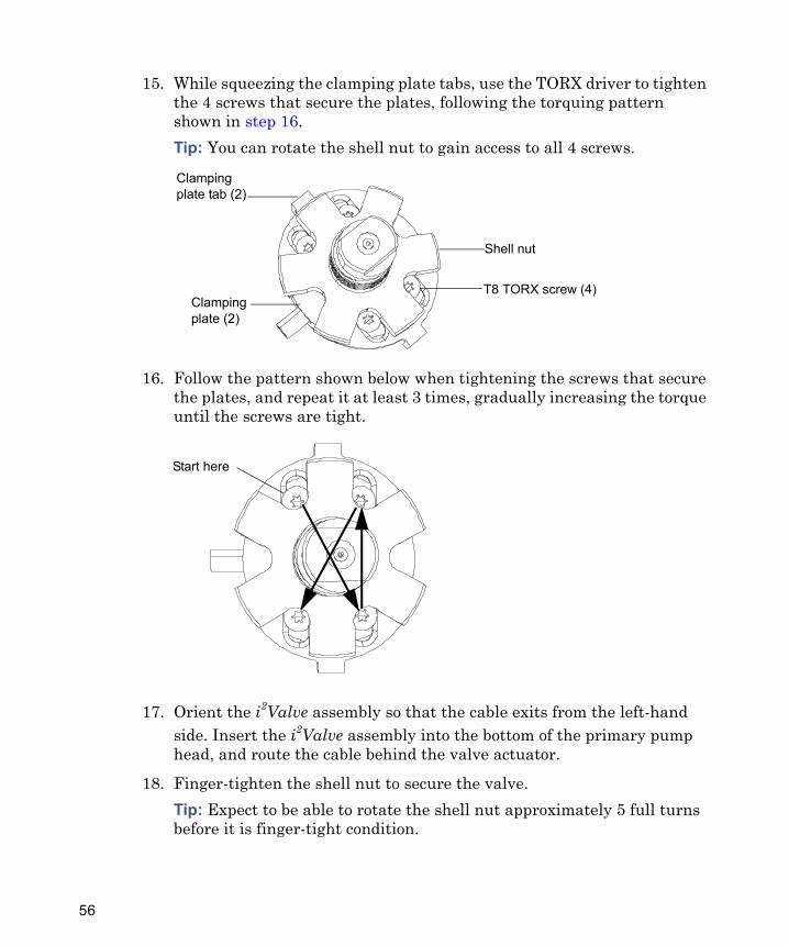
9. Ensure the shell nut remains free to rotate and that the plates slide open.Tips:• Avoid touching the clamping plate tabs when loosening the screws.• You can rotate the shell nut to gain access to all 4 screws.
10. Remove the cartridge from the i2Valve actuator when both plates are in the maximum open position, ensuring the low pressure gasket is also removed.Tip: If you cannot remove the cartridge from the valve actuator, rotate the cartridge 1/2-turn, and then remove it.
11. Ensure the PEEK washer is inserted into the cartridge so that its chamfered edge faces away from the cartridge.
12. Use the T8 TORX driver to loosen 1/2-turn the 4 screws that secure the clamping plates on the new i2Valve actuator.
T8 TORX screw (4)
Shell nut
Clamping plate tab (2)
Clamping plate (2)
PEEK washer
i2Valve cartridge
Chamfered edge facing away from cartridge
Low pressure gasket
44
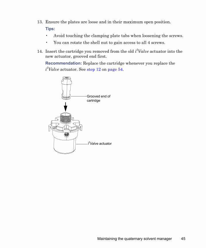
13. Ensure the plates are loose and in their maximum open position.Tips:• Avoid touching the clamping plate tabs when loosening the screws.• You can rotate the shell nut to gain access to all 4 screws.
14. Insert the cartridge you removed from the old i2Valve actuator into the new actuator, grooved end first.Recommendation: Replace the cartridge whenever you replace the i2Valve actuator. See step 12 on page 54.
Grooved end of cartridge
i2Valve actuator
Maintaining the quaternary solvent manager 45
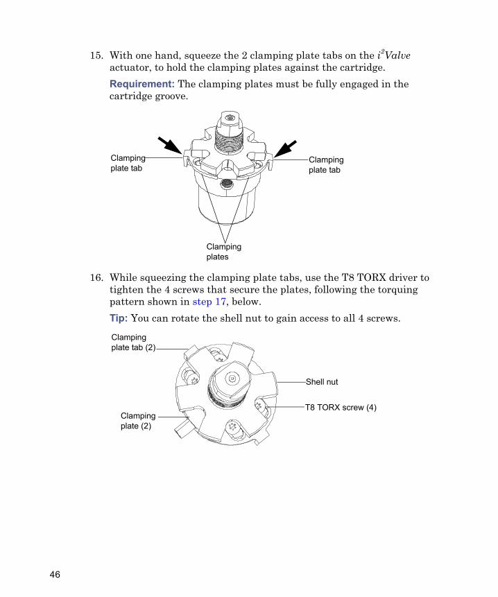
15. With one hand, squeeze the 2 clamping plate tabs on the i2Valve actuator, to hold the clamping plates against the cartridge.Requirement: The clamping plates must be fully engaged in the cartridge groove.
16. While squeezing the clamping plate tabs, use the T8 TORX driver to tighten the 4 screws that secure the plates, following the torquing pattern shown in step 17, below.Tip: You can rotate the shell nut to gain access to all 4 screws.
Clamping plate tab
Clamping plate tab
Clamping plates
T8 TORX screw (4)
Shell nut
Clamping plate tab (2)
Clamping plate (2)
46
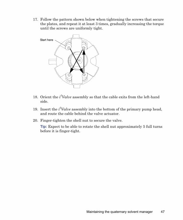
17. Follow the pattern shown below when tightening the screws that secure the plates, and repeat it at least 3 times, gradually increasing the torque until the screws are uniformly tight.
18. Orient the i2Valve assembly so that the cable exits from the left-hand side.
19. Insert the i2Valve assembly into the bottom of the primary pump head, and route the cable behind the valve actuator.
20. Finger-tighten the shell nut to secure the valve.Tip: Expect to be able to rotate the shell nut approximately 5 full turns before it is finger-tight.
Start here
Maintaining the quaternary solvent manager 47
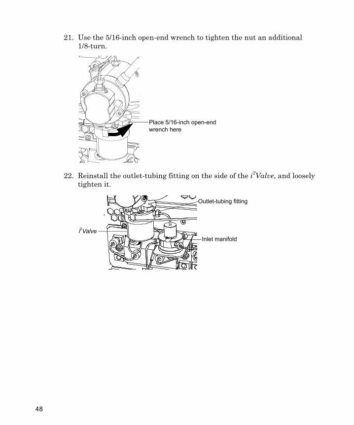
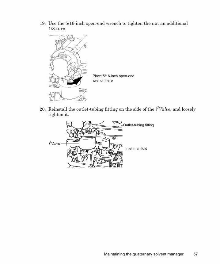
21. Use the 5/16-inch open-end wrench to tighten the nut an additional 1/8-turn.
22. Reinstall the outlet-tubing fitting on the side of the i2Valve, and loosely tighten it.
Place 5/16-inch open-end wrench here
Outlet-tubing fitting
Inlet manifoldi2Valve
48
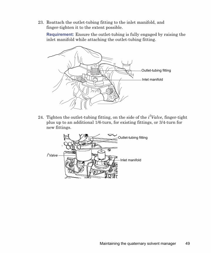
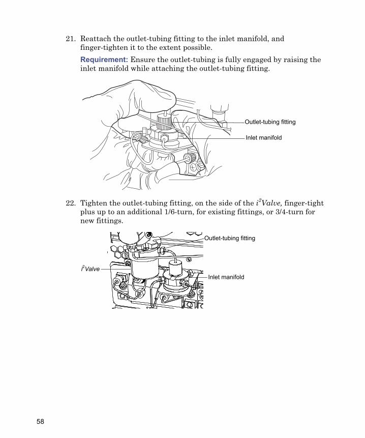
23. Reattach the outlet-tubing fitting to the inlet manifold, and finger-tighten it to the extent possible.Requirement: Ensure the outlet-tubing is fully engaged by raising the inlet manifold while attaching the outlet-tubing fitting.
24. Tighten the outlet-tubing fitting, on the side of the i2Valve, finger-tight plus up to an additional 1/6-turn, for existing fittings, or 3/4-turn for new fittings.
Outlet-tubing fitting
Inlet manifold
Outlet-tubing fitting
Inlet manifoldi2Valve
Maintaining the quaternary solvent manager 49
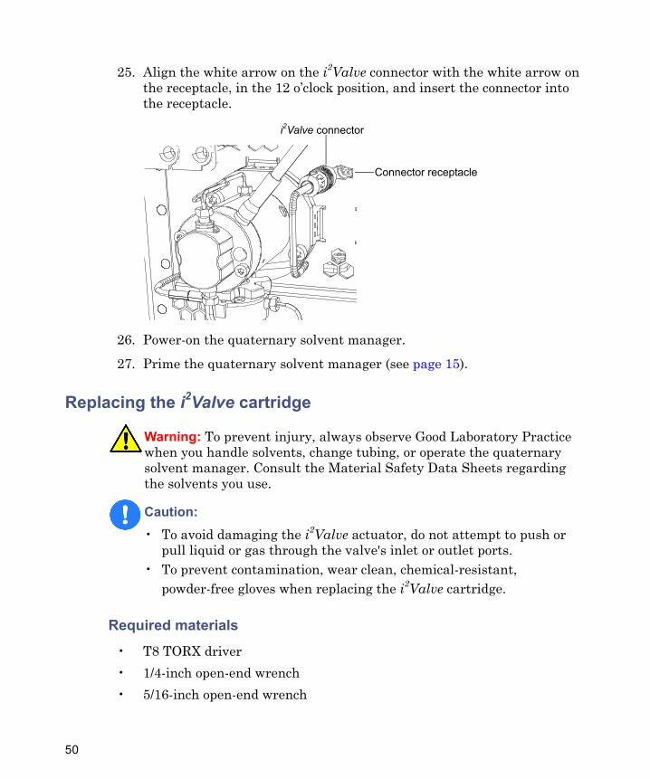
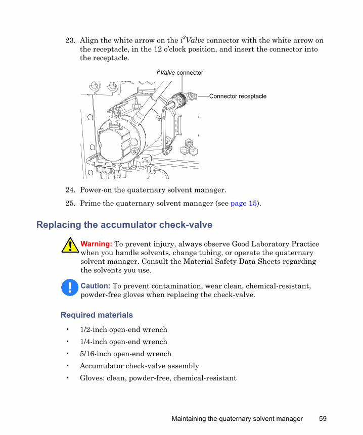
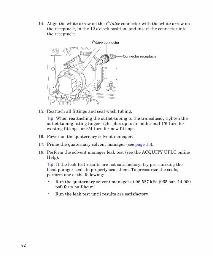
25. Align the white arrow on the i2Valve connector with the white arrow on the receptacle, in the 12 o’clock position, and insert the connector into the receptacle.
26. Power-on the quaternary solvent manager.
27. Prime the quaternary solvent manager (see page 15).
Replacing the i2Valve cartridge
Required materials
• T8 TORX driver• 1/4-inch open-end wrench• 5/16-inch open-end wrench
Warning: To prevent injury, always observe Good Laboratory Practice when you handle solvents, change tubing, or operate the quaternary solvent manager. Consult the Material Safety Data Sheets regarding the solvents you use.
Caution: • To avoid damaging the i2Valve actuator, do not attempt to push or
pull liquid or gas through the valve's inlet or outlet ports.• To prevent contamination, wear clean, chemical-resistant,
powder-free gloves when replacing the i2Valve cartridge.
i2Valve connector
Connector receptacle
50
• Gloves: clean, powder-free, chemical-resistant
• i2Valve cartridge
To replace the i2Valve cartridge:
1. Flush the quaternary solvent manager with nonhazardous solvent.
2. Power-off the quaternary solvent manager.Tip: The quaternary solvent manager is referred to as “pump” on the warning label affixed to the i2Valve actuator.
3. Grasp the i2Valve connector by the knurled diameter, and pull it toward you, disconnecting it from its receptacle.
Caution: To avoid damaging electrical parts, never disconnect an electrical assembly while power is applied to an instrument or device. To completely interrupt power, set the power switch to Off, and then unplug the power cord from the AC source. Wait 10 seconds thereafter before you disconnect an assembly.
i2Valve connector
Knurled diameter
Connector receptacle
Maintaining the quaternary solvent manager 51
4. Loosen the finger-tight outlet-tubing fitting on the inlet manifold outlet.
5. Use the 1/4-inch open-end wrench to disconnect the inlet manifold outlet-tubing fitting on the side of the i2Valve and remove the tubing.
6. Use the 5/16-inch open-end wrench to loosen the shell nut, and then fully unscrew it.
Inlet manifold
Finger-tight outlet-tubing fitting
Outlet-tubing fitting
Inlet manifoldi2Valve
Place 5/16-inch open-end wrench here
52
7. Remove the i2Valve actuator from the bottom of the primary pump head.
8. Use the T8 TORX driver to loosen 1/2-turn the 4 screws that secure the plates.
Caution: • When you remove the valve assembly, ensure the PEEK
washer, which is normally on the top face of the i2Valve cartridge, does not remain in the head. See page 54.
• Never place the actuator assembly or electrical connector in the drip tray.
Caution: To avoid damaging the i2Valve actuator, do not back the screws out fully.
Bottom of primary pump head
i2Valve actuator
Maintaining the quaternary solvent manager 53

9. Ensure the shell remains free to rotate and that the plates slide open.Tips:• Avoid touching the clamping plate tabs when loosening the screws.• You can rotate the shell nut to gain access to all 4 screws.
10. Remove the cartridge from the i2Valve actuator when both plates are in the maximum open position, ensuring that the low pressure gasket is also removed (see page 54).Tip: If you cannot remove the cartridge from the valve actuator, rotate the cartridge 1/2-turn, and then remove it.
11. Unpack the new cartridge.
12. Ensure the PEEK washer is inserted into the cartridge so that its chamfered edge faces away from the cartridge.
T8 TORX screw (4)
Shell nut
Clamping plate tab (2)
Clamping plate (2)
PEEK washer
i2Valve cartridge
Chamfered edge facing away from cartridge
Low pressure gasket
54
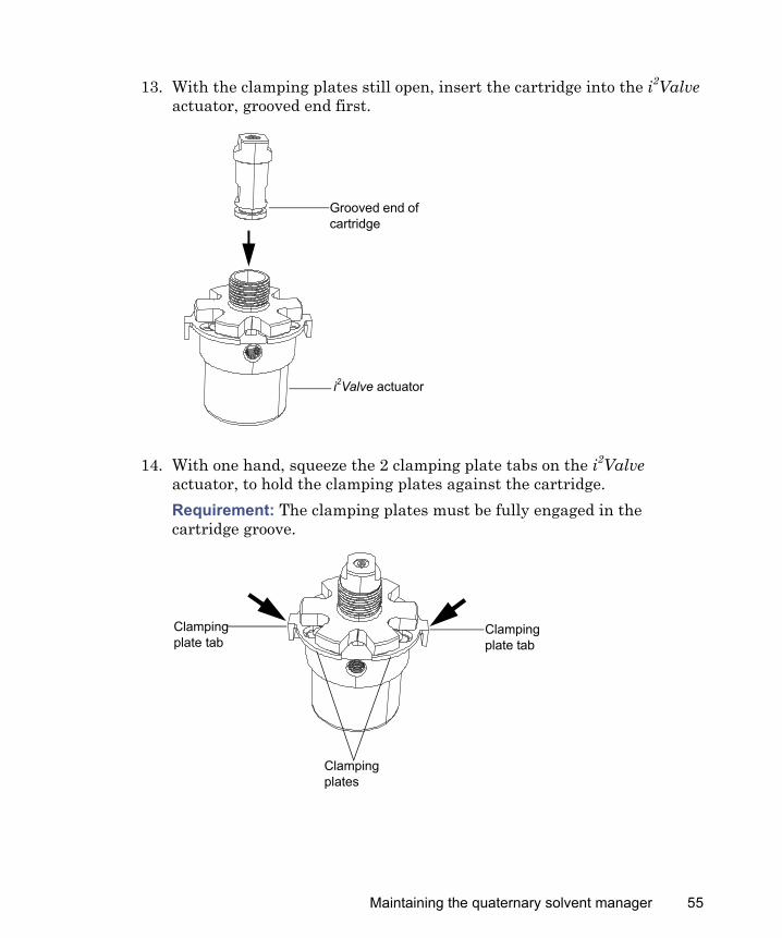
13. With the clamping plates still open, insert the cartridge into the i2Valve actuator, grooved end first.
14. With one hand, squeeze the 2 clamping plate tabs on the i2Valve actuator, to hold the clamping plates against the cartridge.Requirement: The clamping plates must be fully engaged in the cartridge groove.
Grooved end of cartridge
i2Valve actuator
Clamping plate tab
Clamping plate tab
Clamping plates
Maintaining the quaternary solvent manager 55
15. While squeezing the clamping plate tabs, use the TORX driver to tighten the 4 screws that secure the plates, following the torquing pattern shown in step 16.Tip: You can rotate the shell nut to gain access to all 4 screws.
16. Follow the pattern shown below when tightening the screws that secure the plates, and repeat it at least 3 times, gradually increasing the torque until the screws are tight.
17. Orient the i2Valve assembly so that the cable exits from the left-hand side. Insert the i2Valve assembly into the bottom of the primary pump head, and route the cable behind the valve actuator.
18. Finger-tighten the shell nut to secure the valve.Tip: Expect to be able to rotate the shell nut approximately 5 full turns before it is finger-tight condition.
T8 TORX screw (4)
Shell nut
Clamping plate tab (2)
Clamping plate (2)
Start here
56
19. Use the 5/16-inch open-end wrench to tighten the nut an additional 1/8-turn.
20. Reinstall the outlet-tubing fitting on the side of the i2Valve, and loosely tighten it.
Place 5/16-inch open-end wrench here
Outlet-tubing fitting
Inlet manifoldi2Valve
Maintaining the quaternary solvent manager 57
21. Reattach the outlet-tubing fitting to the inlet manifold, and finger-tighten it to the extent possible.Requirement: Ensure the outlet-tubing is fully engaged by raising the inlet manifold while attaching the outlet-tubing fitting.
22. Tighten the outlet-tubing fitting, on the side of the i2Valve, finger-tight plus up to an additional 1/6-turn, for existing fittings, or 3/4-turn for new fittings.
Outlet-tubing fitting
Inlet manifold
Outlet-tubing fitting
Inlet manifoldi2Valve
58
23. Align the white arrow on the i2Valve connector with the white arrow on the receptacle, in the 12 o’clock position, and insert the connector into the receptacle.
24. Power-on the quaternary solvent manager.
25. Prime the quaternary solvent manager (see page 15).
Replacing the accumulator check-valve
Required materials
• 1/2-inch open-end wrench• 1/4-inch open-end wrench• 5/16-inch open-end wrench• Accumulator check-valve assembly• Gloves: clean, powder-free, chemical-resistant
Warning: To prevent injury, always observe Good Laboratory Practice when you handle solvents, change tubing, or operate the quaternary solvent manager. Consult the Material Safety Data Sheets regarding the solvents you use.
Caution: To prevent contamination, wear clean, chemical-resistant, powder-free gloves when replacing the check-valve.
i2Valve connector
Connector receptacle
Maintaining the quaternary solvent manager 59
To replace the accumulator check-valve:
1. Flush the quaternary solvent manager with nonhazardous solvent.
2. Power-off the quaternary solvent manager.
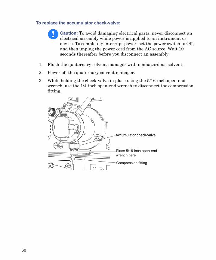
3. While holding the check-valve in place using the 5/16-inch open-end wrench, use the 1/4-inch open-end wrench to disconnect the compression fitting.
Caution: To avoid damaging electrical parts, never disconnect an electrical assembly while power is applied to an instrument or device. To completely interrupt power, set the power switch to Off, and then unplug the power cord from the AC source. Wait 10 seconds thereafter before you disconnect an assembly.
Accumulator check-valve
Compression fitting
Place 5/16-inch open-end wrench here
60
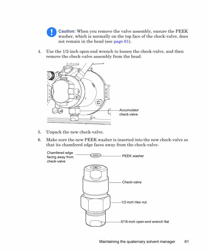
4. Use the 1/2-inch open-end wrench to loosen the check-valve, and then remove the check-valve assembly from the head.
5. Unpack the new check-valve.
6. Make sure the new PEEK washer is inserted into the new check-valve so that its chamfered edge faces away from the check-valve.
Caution: When you remove the valve assembly, ensure the PEEK washer, which is normally on the top face of the check-valve, does not remain in the head (see page 61).
Accumulator check-valve
PEEK washer
Check-valve
Chamfered edge facing away from check-valve
1/2-inch Hex nut
5/16-inch open-end wrench flat
Maintaining the quaternary solvent manager 61
7. Insert the check-valve assembly into the head, and use the 1/2-inch wrench to tighten the check-valve nut 1/8-turn beyond finger-tight.
8. Use the 5/16-inch open-end wrench to hold the check-valve in place, and then reattach the compression fitting to the check-valve.Tip: Use the 1/4-inch wrench to tighten the compression screw up to 1/6-turn beyond finger-tight for existing stainless steel tubing assembly, or 3/4-turn beyond finger-tight for new stainless steel tubing assembly.
9. Power-on the quaternary solvent manager.
10. Prime the quaternary solvent manager (see page 15).
Replacing solvent filters
Required materials
• Gloves: clean, powder-free, chemical-resistant• New solvent filter
To replace a solvent filter:
1. Remove the filtered end of the solvent tubing from the solvent bottle.
2. Remove the old solvent filter from the short piece of PTFE tubing.
Warning: To prevent injury, always observe Good Laboratory Practice when you handle solvents, change tubing, or operate the quaternary solvent manager. Consult the Material Safety Data Sheets regarding the solvents you use.
Caution: Wear clean, chemical-resistant, powder-free gloves when handling the solvent filter. Oil from your hands can contaminate the solvent filter.
62
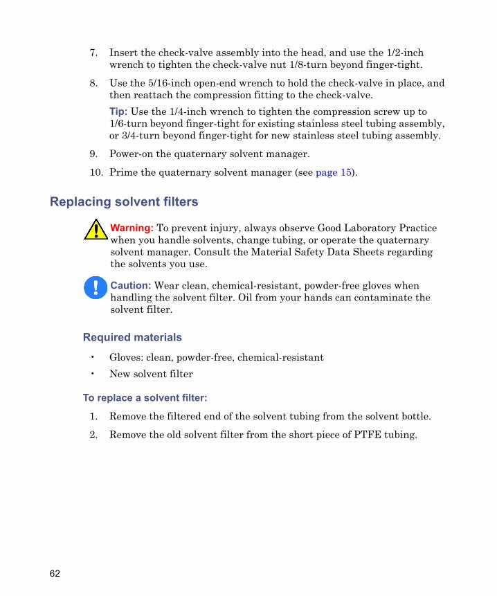
3. Insert the new solvent filter into the PTFE tubing, pushing until it contacts the solvent tubing.
4. Insert the filtered end of the solvent tubing into the solvent bottle.
5. Shake the filter to remove any air from it.
6. Prime the quaternary solvent manager (see page 15).
Cleaning the air filter in the quaternary solvent manager door
Required materials
• T10 TORX driver• Mild detergent and water
Solvent filter
PTFE tubingSolvent tubing
Maintaining the quaternary solvent manager 63
To clean the air filter:
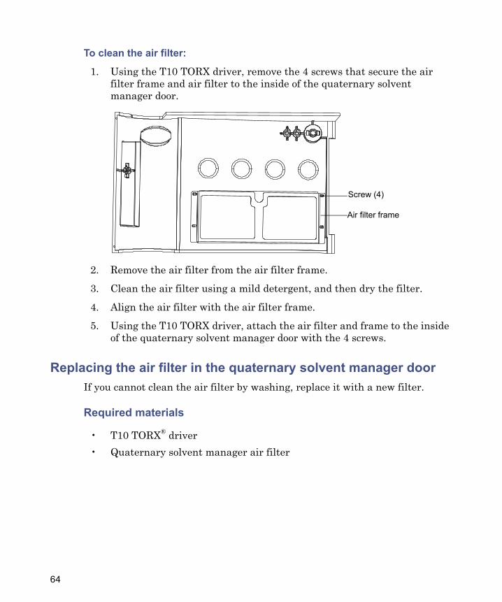
1. Using the T10 TORX driver, remove the 4 screws that secure the air filter frame and air filter to the inside of the quaternary solvent manager door.
2. Remove the air filter from the air filter frame.
3. Clean the air filter using a mild detergent, and then dry the filter.
4. Align the air filter with the air filter frame.
5. Using the T10 TORX driver, attach the air filter and frame to the inside of the quaternary solvent manager door with the 4 screws.
Replacing the air filter in the quaternary solvent manager doorIf you cannot clean the air filter by washing, replace it with a new filter.
Required materials
• T10 TORX® driver• Quaternary solvent manager air filter
Air filter frame
Screw (4)
64
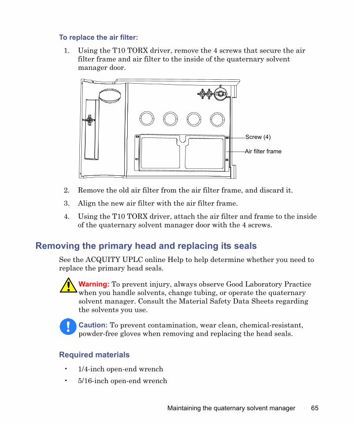
To replace the air filter:
1. Using the T10 TORX driver, remove the 4 screws that secure the air filter frame and air filter to the inside of the quaternary solvent manager door.
2. Remove the old air filter from the air filter frame, and discard it.
3. Align the new air filter with the air filter frame.
4. Using the T10 TORX driver, attach the air filter and frame to the inside of the quaternary solvent manager door with the 4 screws.
Removing the primary head and replacing its sealsSee the ACQUITY UPLC online Help to help determine whether you need to replace the primary head seals.
Required materials
• 1/4-inch open-end wrench• 5/16-inch open-end wrench
Warning: To prevent injury, always observe Good Laboratory Practice when you handle solvents, change tubing, or operate the quaternary solvent manager. Consult the Material Safety Data Sheets regarding the solvents you use.
Caution: To prevent contamination, wear clean, chemical-resistant, powder-free gloves when removing and replacing the head seals.
Air filter frame
Screw (4)
Maintaining the quaternary solvent manager 65

• T27 TORX driver (startup kit)• Gloves: clean, powder-free, chemical-resistant• Head seal and seal wash spacer• Methanol• PTFE O-ring• Seal extraction tool• Seal wash seal• Sharp tool• Plunger (recommended)
To remove the primary head:
1. Flush the quaternary solvent manager with nonhazardous solvent.
2. In the ACQUITY UPLC Console, select Quaternary Solvent Manager from the system tree.
3. In the quaternary solvent manager information window, click Maintain > Heads.
4. In the Head Maintenance dialog box, select the primary head.
5. Click Move Backward, and then wait for the plunger to stop.
6. Power-off the quaternary solvent manager.Tip: The quaternary solvent manager is referred to as “pump” on the warning label affixed to the i2Valve actuator.
Caution: To avoid damaging electrical parts, never disconnect an electrical assembly while power is applied to an instrument or device. To completely interrupt power, set the power switch to Off, and then unplug the power cord from the AC source. Wait 10 seconds thereafter before you disconnect an assembly.
66
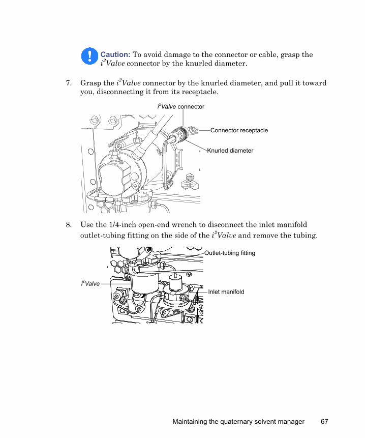
7. Grasp the i2Valve connector by the knurled diameter, and pull it toward you, disconnecting it from its receptacle.
8. Use the 1/4-inch open-end wrench to disconnect the inlet manifold outlet-tubing fitting on the side of the i2Valve and remove the tubing.
Caution: To avoid damage to the connector or cable, grasp the i2Valve connector by the knurled diameter.
i2Valve connector
Knurled diameter
Connector receptacle
Outlet-tubing fitting
Inlet manifoldi2Valve
Maintaining the quaternary solvent manager 67
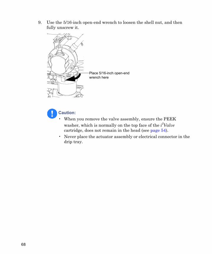
9. Use the 5/16-inch open-end wrench to loosen the shell nut, and then fully unscrew it.
Caution: • When you remove the valve assembly, ensure the PEEK
washer, which is normally on the top face of the i2Valve cartridge, does not remain in the head (see page 54).
• Never place the actuator assembly or electrical connector in the drip tray.
Place 5/16-inch open-end wrench here
68
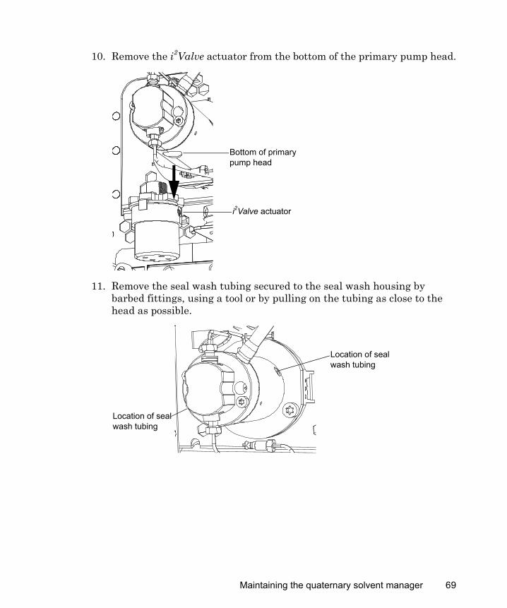
10. Remove the i2Valve actuator from the bottom of the primary pump head.
11. Remove the seal wash tubing secured to the seal wash housing by barbed fittings, using a tool or by pulling on the tubing as close to the head as possible.
Bottom of primary pump head
i2Valve actuator
Location of seal wash tubing
Location of seal wash tubing
Maintaining the quaternary solvent manager 69
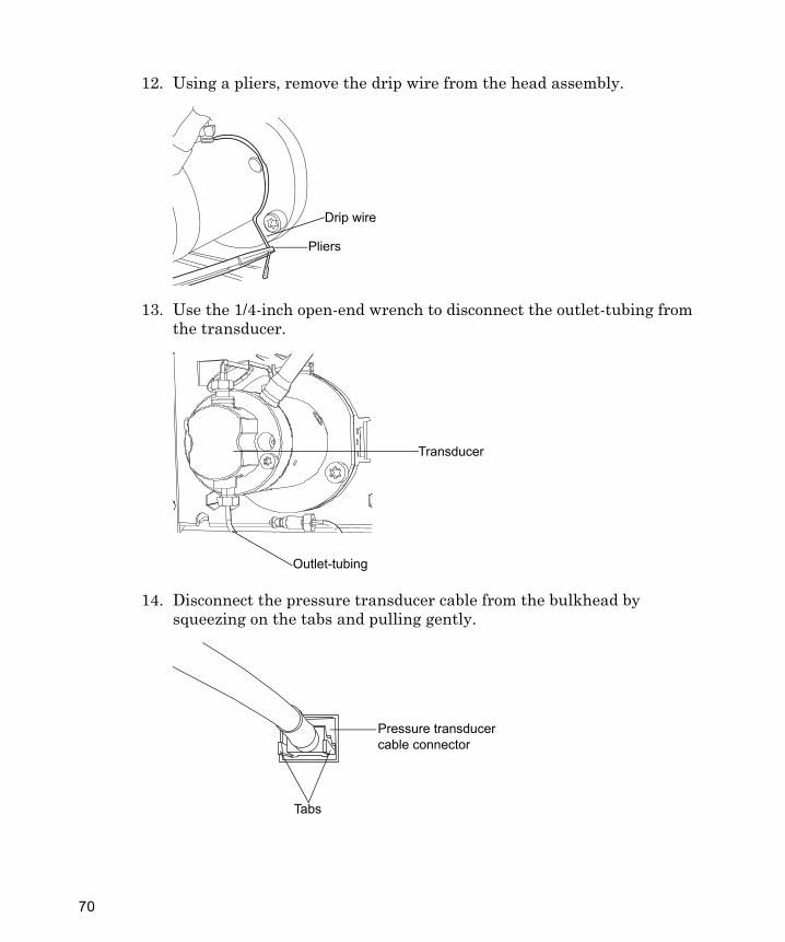
12. Using a pliers, remove the drip wire from the head assembly.
13. Use the 1/4-inch open-end wrench to disconnect the outlet-tubing from the transducer.
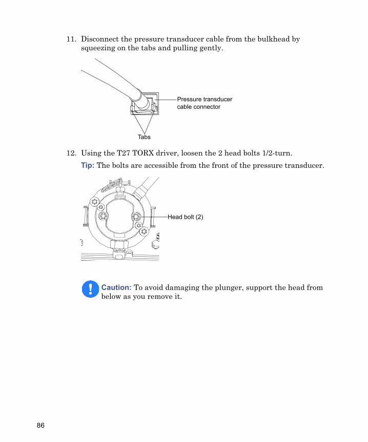
14. Disconnect the pressure transducer cable from the bulkhead by squeezing on the tabs and pulling gently.
Drip wire
Pliers
Transducer
Outlet-tubing
Pressure transducer cable connector
Tabs
70
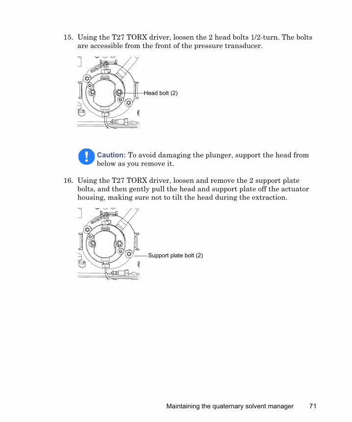
15. Using the T27 TORX driver, loosen the 2 head bolts 1/2-turn. The bolts are accessible from the front of the pressure transducer.
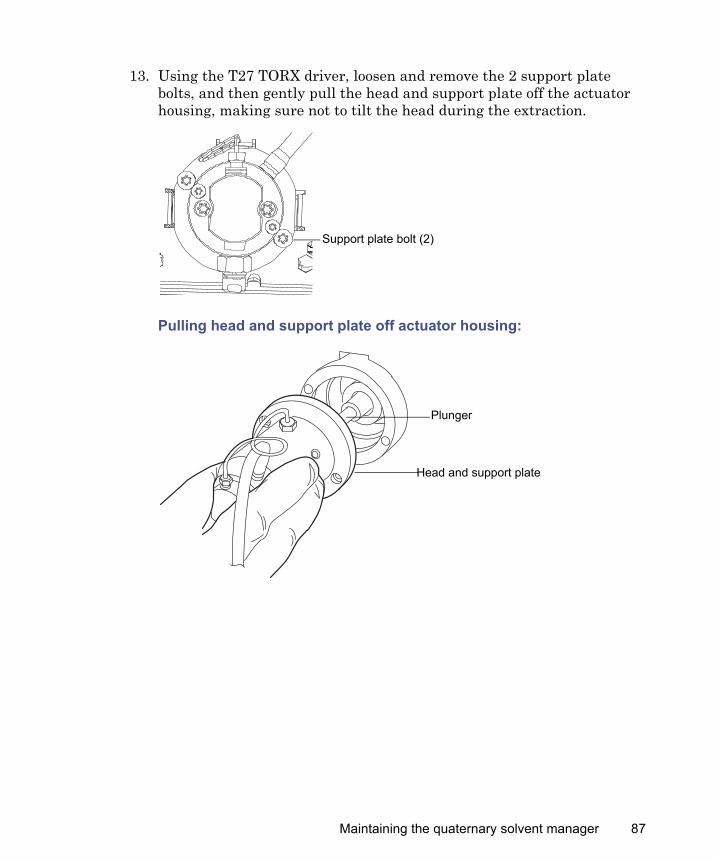
16. Using the T27 TORX driver, loosen and remove the 2 support plate bolts, and then gently pull the head and support plate off the actuator housing, making sure not to tilt the head during the extraction.
Caution: To avoid damaging the plunger, support the head from below as you remove it.
Head bolt (2)
Support plate bolt (2)
Maintaining the quaternary solvent manager 71
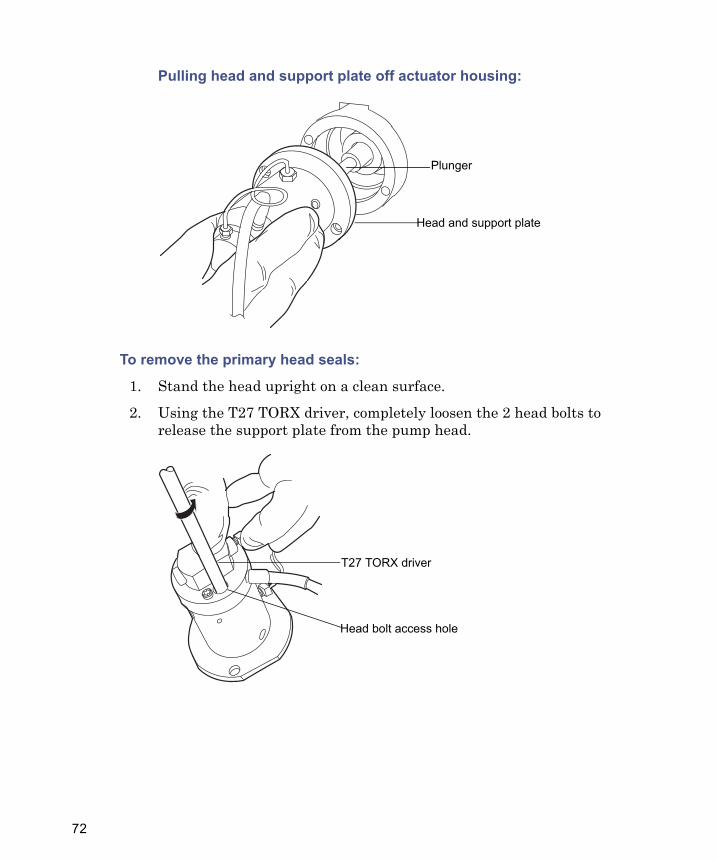
Pulling head and support plate off actuator housing:
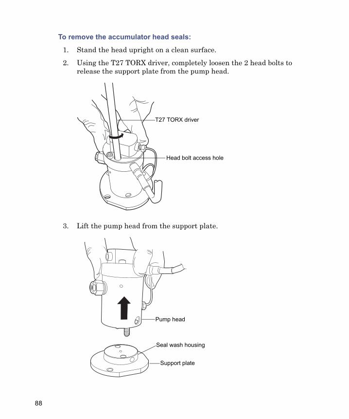
To remove the primary head seals:
1. Stand the head upright on a clean surface.
2. Using the T27 TORX driver, completely loosen the 2 head bolts to release the support plate from the pump head.
Head and support plate
Plunger
T27 TORX driver
Head bolt access hole
72
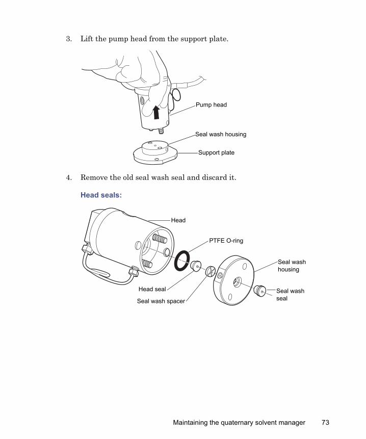
3. Lift the pump head from the support plate.
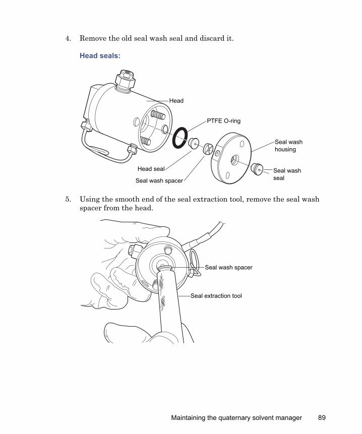
4. Remove the old seal wash seal and discard it.
Head seals:
Support plate
Pump head
Seal wash housing
Seal wash housing
Seal wash seal
Head
PTFE O-ring
Head seal
Seal wash spacer
Maintaining the quaternary solvent manager 73
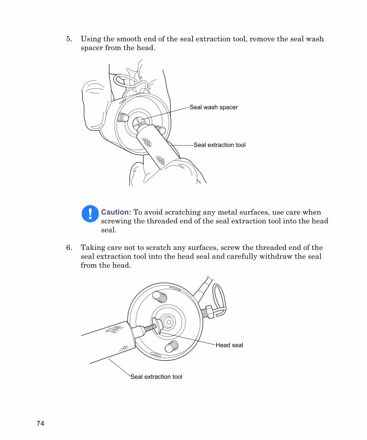
5. Using the smooth end of the seal extraction tool, remove the seal wash spacer from the head.
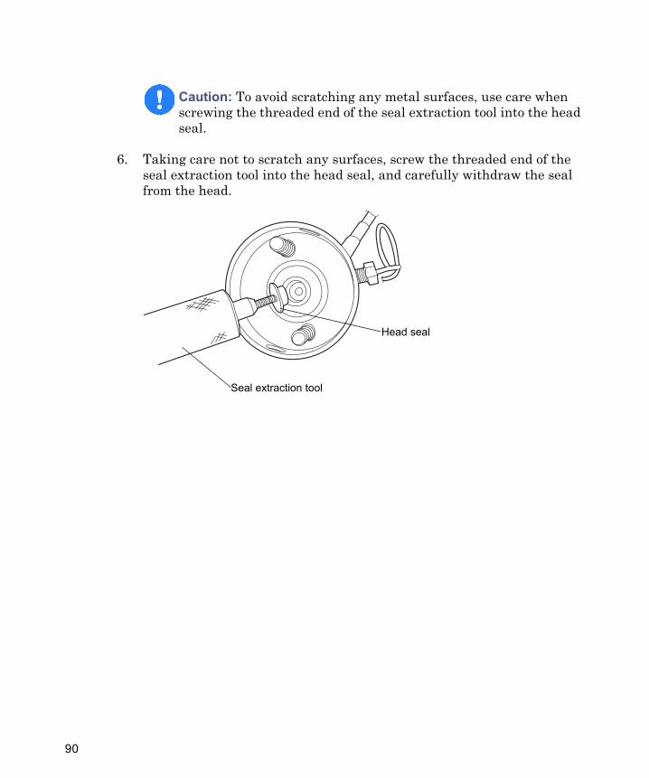
6. Taking care not to scratch any surfaces, screw the threaded end of the seal extraction tool into the head seal and carefully withdraw the seal from the head.
Caution: To avoid scratching any metal surfaces, use care when screwing the threaded end of the seal extraction tool into the head seal.
Seal extraction tool
Seal wash spacer
TP03001
Seal extraction tool
Head seal
74
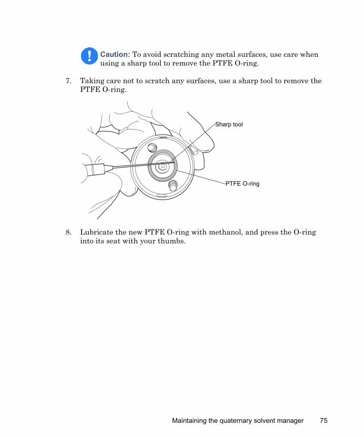
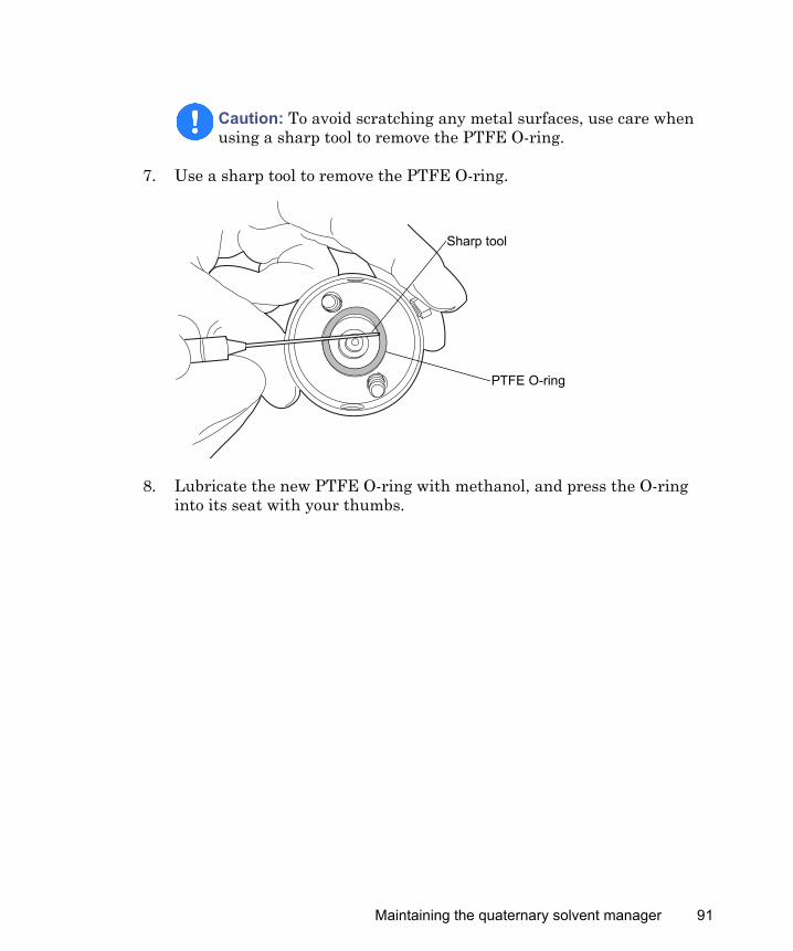
7. Taking care not to scratch any surfaces, use a sharp tool to remove the PTFE O-ring.
8. Lubricate the new PTFE O-ring with methanol, and press the O-ring into its seat with your thumbs.
Caution: To avoid scratching any metal surfaces, use care when using a sharp tool to remove the PTFE O-ring.
Sharp tool
PTFE O-ring
Maintaining the quaternary solvent manager 75
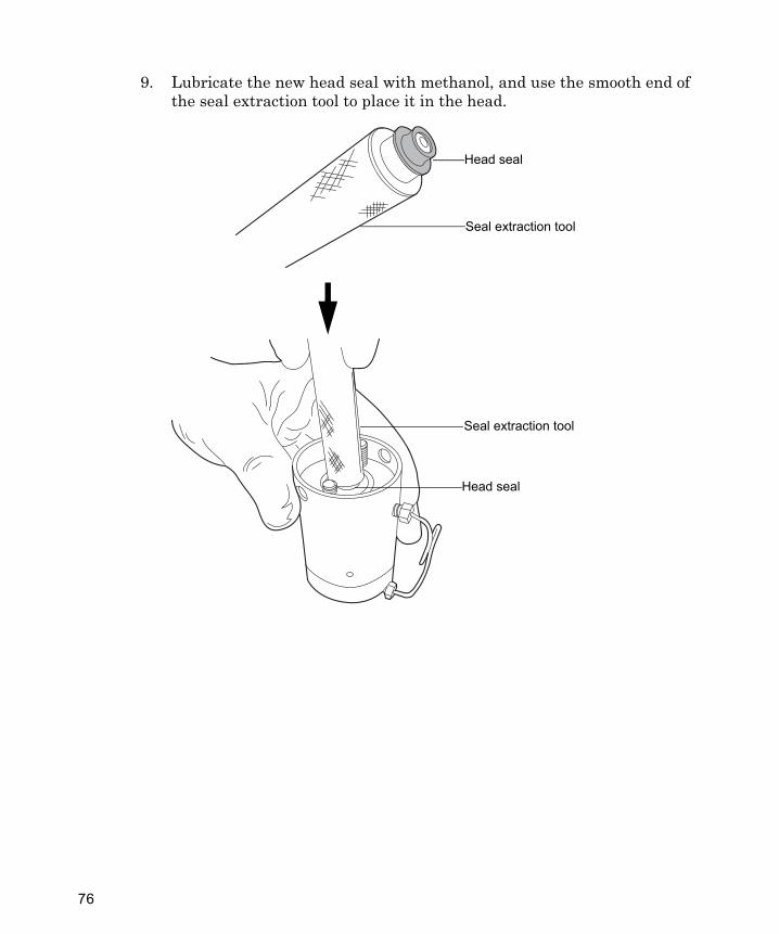
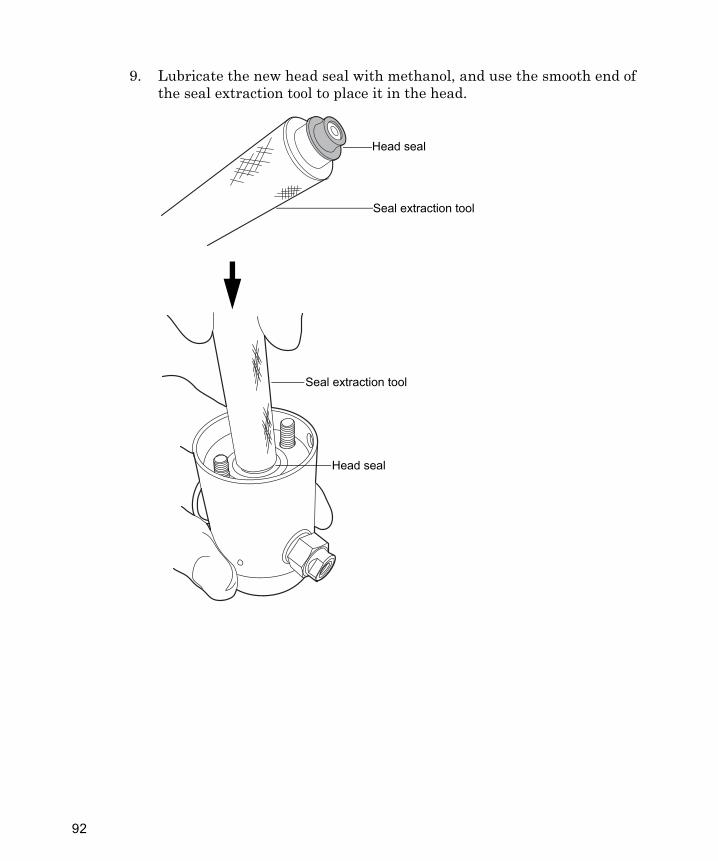
9. Lubricate the new head seal with methanol, and use the smooth end of the seal extraction tool to place it in the head.
TP02971
Head seal
Seal extraction tool
Head seal
Seal extraction tool
76
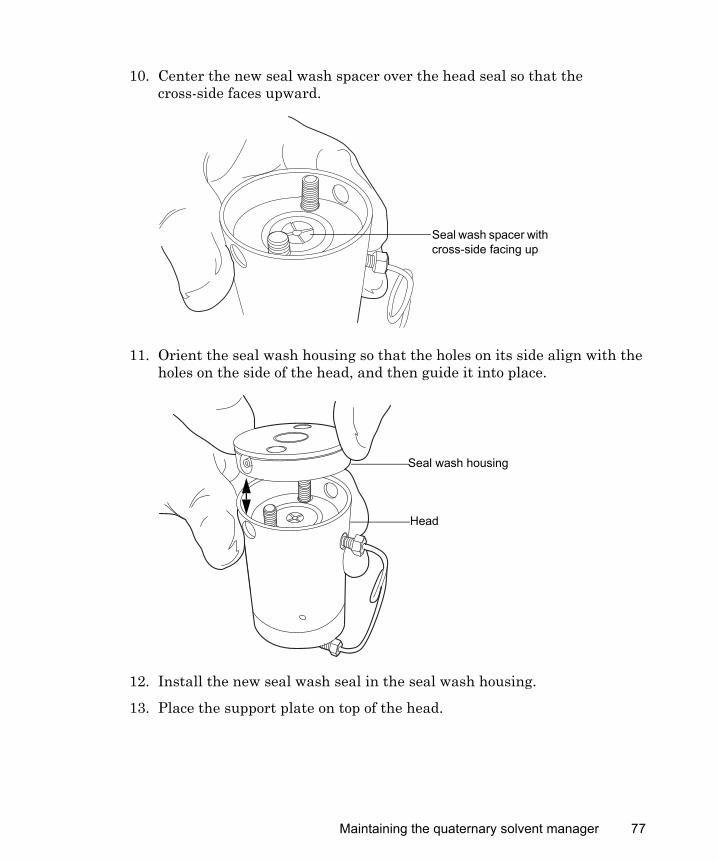
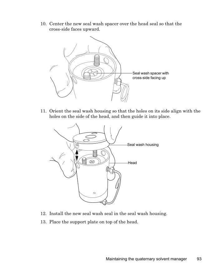
10. Center the new seal wash spacer over the head seal so that the cross-side faces upward.
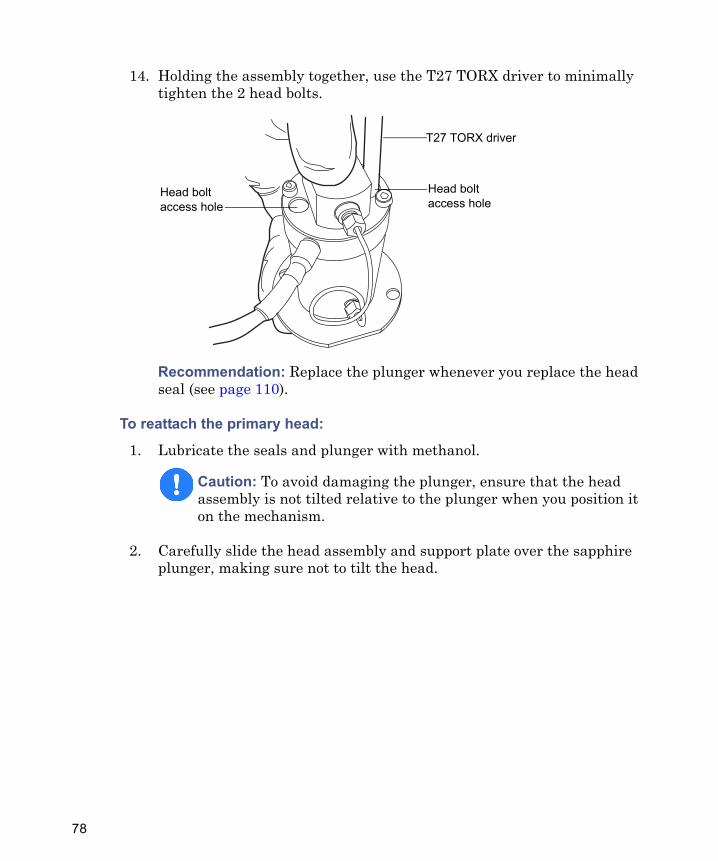
11. Orient the seal wash housing so that the holes on its side align with the holes on the side of the head, and then guide it into place.
12. Install the new seal wash seal in the seal wash housing.
13. Place the support plate on top of the head.
Seal wash spacer with cross-side facing up
Head
Seal wash housing
Maintaining the quaternary solvent manager 77
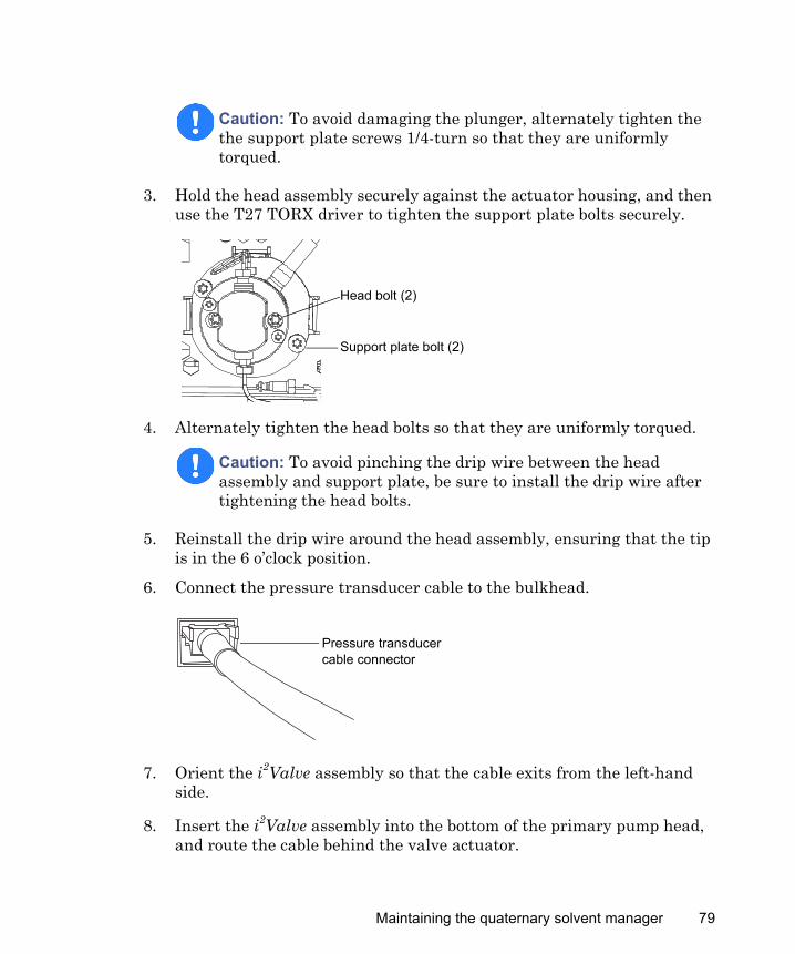
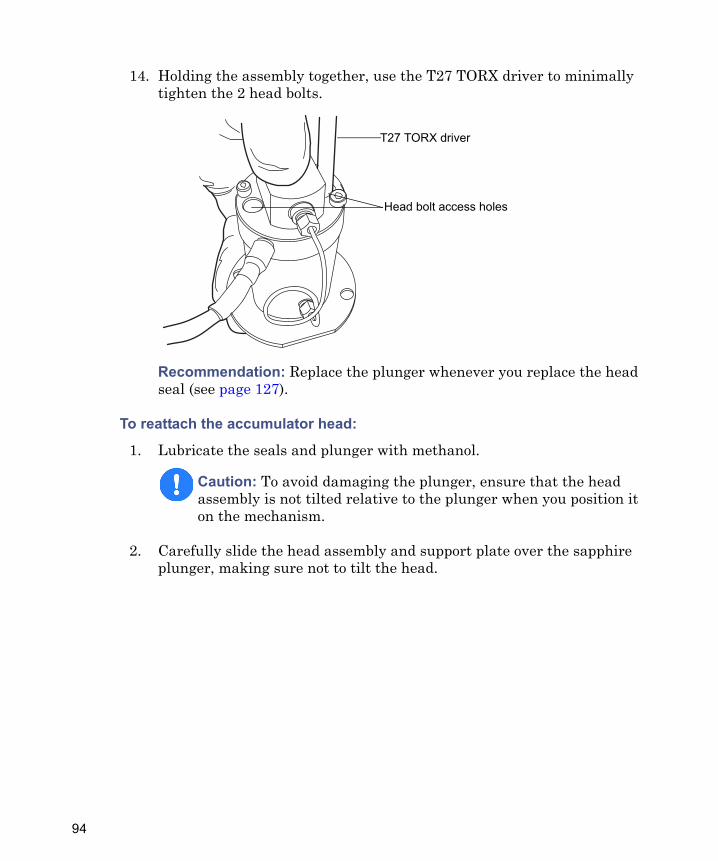
14. Holding the assembly together, use the T27 TORX driver to minimally tighten the 2 head bolts.
Recommendation: Replace the plunger whenever you replace the head seal (see page 110).
To reattach the primary head:
1. Lubricate the seals and plunger with methanol.
2. Carefully slide the head assembly and support plate over the sapphire plunger, making sure not to tilt the head.
Caution: To avoid damaging the plunger, ensure that the head assembly is not tilted relative to the plunger when you position it on the mechanism.
T27 TORX driver
Head bolt access hole
Head bolt access hole
78
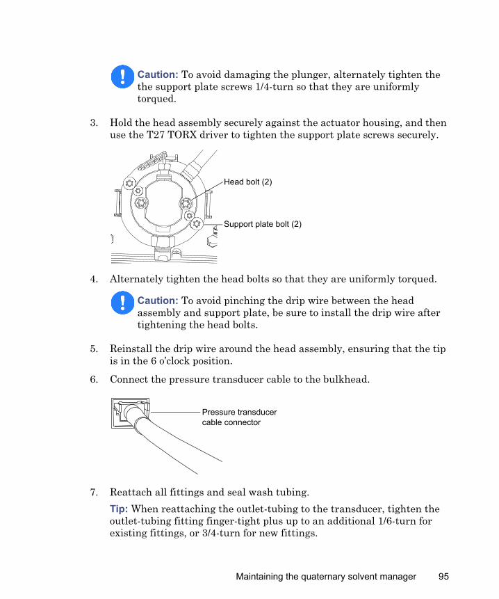
3. Hold the head assembly securely against the actuator housing, and then use the T27 TORX driver to tighten the support plate bolts securely.
4. Alternately tighten the head bolts so that they are uniformly torqued.
5. Reinstall the drip wire around the head assembly, ensuring that the tip is in the 6 o’clock position.
6. Connect the pressure transducer cable to the bulkhead.
7. Orient the i2Valve assembly so that the cable exits from the left-hand side.
8. Insert the i2Valve assembly into the bottom of the primary pump head, and route the cable behind the valve actuator.
Caution: To avoid damaging the plunger, alternately tighten the the support plate screws 1/4-turn so that they are uniformly torqued.
Caution: To avoid pinching the drip wire between the head assembly and support plate, be sure to install the drip wire after tightening the head bolts.
Support plate bolt (2)
Head bolt (2)
Pressure transducer cable connector
Maintaining the quaternary solvent manager 79
9. Finger-tighten the shell nut to secure the valve.Tip: Expect to be able to rotate the shell nut approximately 5 full turns before it is finger-tight.
10. Use the 5/16-inch open-end wrench to tighten the nut an additional 1/8-turn.
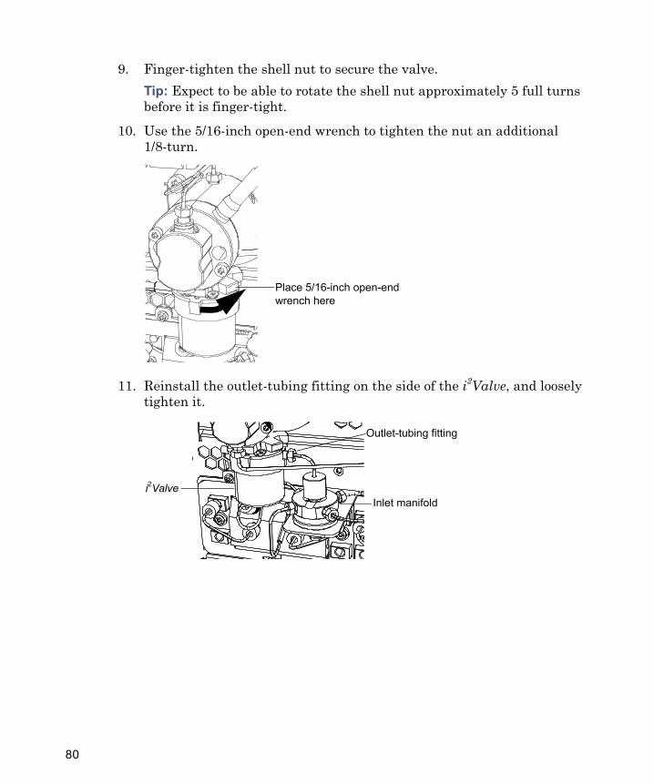
11. Reinstall the outlet-tubing fitting on the side of the i2Valve, and loosely tighten it.
Place 5/16-inch open-end wrench here
Outlet-tubing fitting
Inlet manifoldi2Valve
80

12. Reattach the outlet-tubing fitting to the inlet manifold, and finger-tighten it to the extent possible.Requirement: Ensure the outlet-tubing is fully engaged by raising the inlet manifold while attaching the outlet-tubing fitting.
13. Tighten the outlet-tubing fitting, on the side of the i2Valve, finger-tight plus up to an additional 1/6-turn, for existing fittings, or 3/4-turn for new fittings.
Outlet-tubing fitting
Inlet manifold
Outlet-tubing fitting
Inlet manifoldi2Valve
Maintaining the quaternary solvent manager 81
14. Align the white arrow on the i2Valve connector with the white arrow on the receptacle, in the 12 o’clock position, and insert the connector into the receptacle.
15. Reattach all fittings and seal wash tubing.Tip: When reattaching the outlet-tubing to the transducer, tighten the outlet-tubing fitting finger-tight plus up to an additional 1/6-turn for existing fittings, or 3/4-turn for new fittings.
16. Power-on the quaternary solvent manager.
17. Prime the quaternary solvent manager (see page 15).
18. Perform the solvent manager leak test (see the ACQUITY UPLC online Help).Tip: If the leak test results are not satisfactory, try pressurizing the head plunger seals to properly seat them. To pressurize the seals, perform one of the following:• Run the quaternary solvent manager at 96,527 kPa (965 bar, 14,000
psi) for a half-hour.• Run the leak test until results are satisfactory.
i2Valve connector
Connector receptacle
82
Removing the accumulator head and replacing its sealsSee the ACQUITY UPLC online Help to help determine whether you need to replace the accumulator head seals.
Required materials
• 1/4-inch open-end wrench• 5/16-inch open-end wrench• T27 TORX driver (startup kit)• Gloves: clean, powder-free, chemical-resistant• Head seal and seal wash spacer• Methanol• Plunger (recommended)• Plunger removal tool (recommended)• PTFE O-ring• Seal extraction tool• Seal wash seal• Sharp tool
To remove the accumulator head:
1. Flush the quaternary solvent manager with nonhazardous solvent.
2. In the ACQUITY UPLC Console, select Quaternary Solvent Manager from the system tree.
3. In the quaternary solvent manager information window, click Maintain > Heads.
4. In the Head Maintenance dialog box, select the accumulator head.
Warning: To prevent injury, always observe Good Laboratory Practice when you handle solvents, change tubing, or operate the quaternary solvent manager. Consult the Material Safety Data Sheets regarding the solvents you use.
Caution: To prevent contamination, wear clean, chemical-resistant, powder-free gloves when removing and replacing the head seals.
Maintaining the quaternary solvent manager 83
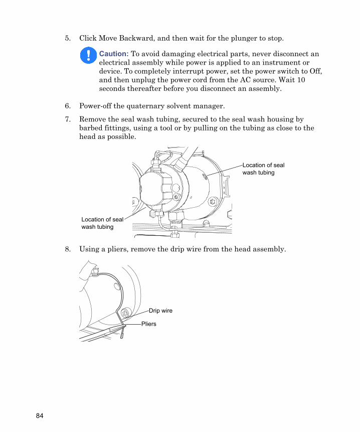
5. Click Move Backward, and then wait for the plunger to stop.
6. Power-off the quaternary solvent manager.
7. Remove the seal wash tubing, secured to the seal wash housing by barbed fittings, using a tool or by pulling on the tubing as close to the head as possible.
8. Using a pliers, remove the drip wire from the head assembly.
Caution: To avoid damaging electrical parts, never disconnect an electrical assembly while power is applied to an instrument or device. To completely interrupt power, set the power switch to Off, and then unplug the power cord from the AC source. Wait 10 seconds thereafter before you disconnect an assembly.
Location of seal wash tubing
Location of seal wash tubing
Drip wire
Pliers
84
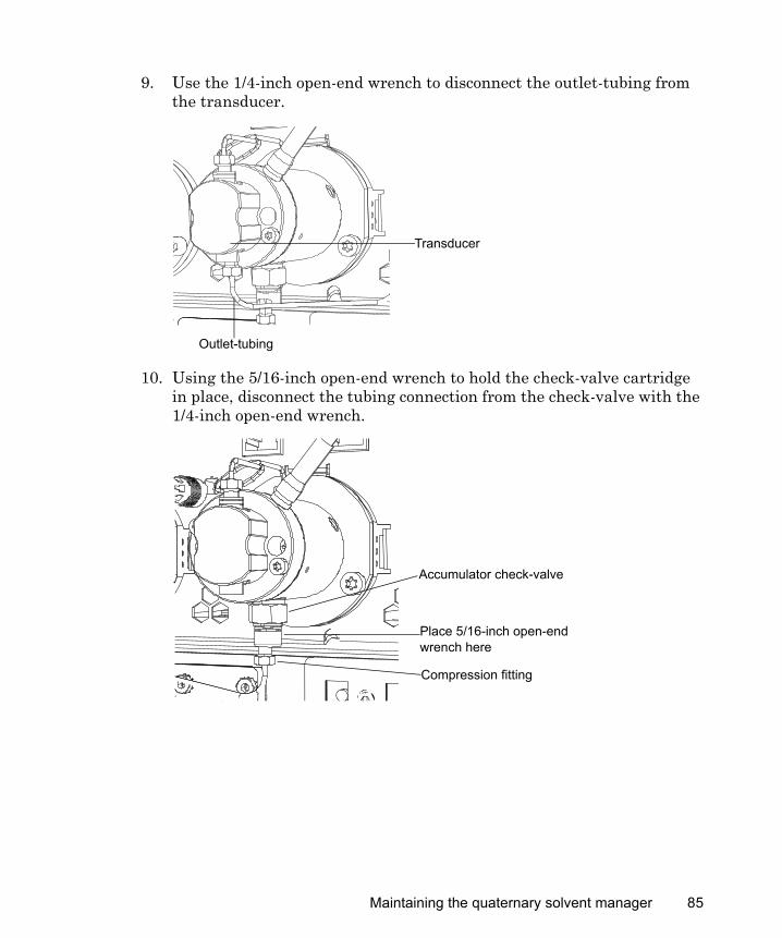
9. Use the 1/4-inch open-end wrench to disconnect the outlet-tubing from the transducer.
10. Using the 5/16-inch open-end wrench to hold the check-valve cartridge in place, disconnect the tubing connection from the check-valve with the 1/4-inch open-end wrench.
Transducer
Outlet-tubing
Accumulator check-valve
Compression fitting
Place 5/16-inch open-end wrench here
Maintaining the quaternary solvent manager 85
11. Disconnect the pressure transducer cable from the bulkhead by squeezing on the tabs and pulling gently.
12. Using the T27 TORX driver, loosen the 2 head bolts 1/2-turn.Tip: The bolts are accessible from the front of the pressure transducer.
Caution: To avoid damaging the plunger, support the head from below as you remove it.
Pressure transducer cable connector
Tabs
Head bolt (2)
86
13. Using the T27 TORX driver, loosen and remove the 2 support plate bolts, and then gently pull the head and support plate off the actuator housing, making sure not to tilt the head during the extraction.
Pulling head and support plate off actuator housing:
Support plate bolt (2)
Head and support plate
Plunger
Maintaining the quaternary solvent manager 87
To remove the accumulator head seals:
1. Stand the head upright on a clean surface.
2. Using the T27 TORX driver, completely loosen the 2 head bolts to release the support plate from the pump head.
3. Lift the pump head from the support plate.
TP02989
T27 TORX driver
Head bolt access hole
TP02987
Support plate
Pump head
Seal wash housing
88
4. Remove the old seal wash seal and discard it.
Head seals:
5. Using the smooth end of the seal extraction tool, remove the seal wash spacer from the head.
Seal wash housing
Seal wash seal
Head
PTFE O-ring
Head seal
Seal wash spacer
Seal extraction tool
Seal wash spacer
Maintaining the quaternary solvent manager 89
6. Taking care not to scratch any surfaces, screw the threaded end of the seal extraction tool into the head seal, and carefully withdraw the seal from the head.
Caution: To avoid scratching any metal surfaces, use care when screwing the threaded end of the seal extraction tool into the head seal.
TP03001
Seal extraction tool
Head seal
90
7. Use a sharp tool to remove the PTFE O-ring.
8. Lubricate the new PTFE O-ring with methanol, and press the O-ring into its seat with your thumbs.
Caution: To avoid scratching any metal surfaces, use care when using a sharp tool to remove the PTFE O-ring.
Sharp tool
PTFE O-ring
Maintaining the quaternary solvent manager 91
9. Lubricate the new head seal with methanol, and use the smooth end of the seal extraction tool to place it in the head.
Head seal
Seal extraction tool
TP02971
Head seal
Seal extraction tool
92
10. Center the new seal wash spacer over the head seal so that the cross-side faces upward.
11. Orient the seal wash housing so that the holes on its side align with the holes on the side of the head, and then guide it into place.
12. Install the new seal wash seal in the seal wash housing.
13. Place the support plate on top of the head.
Seal wash spacer with cross-side facing up
Head
Seal wash housing
Maintaining the quaternary solvent manager 93
14. Holding the assembly together, use the T27 TORX driver to minimally tighten the 2 head bolts.
Recommendation: Replace the plunger whenever you replace the head seal (see page 127).
To reattach the accumulator head:
1. Lubricate the seals and plunger with methanol.
2. Carefully slide the head assembly and support plate over the sapphire plunger, making sure not to tilt the head.
Caution: To avoid damaging the plunger, ensure that the head assembly is not tilted relative to the plunger when you position it on the mechanism.
T27 TORX driver
Head bolt access holes
94
3. Hold the head assembly securely against the actuator housing, and then use the T27 TORX driver to tighten the support plate screws securely.
4. Alternately tighten the head bolts so that they are uniformly torqued.
5. Reinstall the drip wire around the head assembly, ensuring that the tip is in the 6 o’clock position.
6. Connect the pressure transducer cable to the bulkhead.
7. Reattach all fittings and seal wash tubing.Tip: When reattaching the outlet-tubing to the transducer, tighten the outlet-tubing fitting finger-tight plus up to an additional 1/6-turn for existing fittings, or 3/4-turn for new fittings.
Caution: To avoid damaging the plunger, alternately tighten the the support plate screws 1/4-turn so that they are uniformly torqued.
Caution: To avoid pinching the drip wire between the head assembly and support plate, be sure to install the drip wire after tightening the head bolts.
Support plate bolt (2)
Head bolt (2)
Pressure transducer cable connector
Maintaining the quaternary solvent manager 95
8. Power-on the quaternary solvent manager.
9. Prime the quaternary solvent manager (see page 15).
10. Perform the solvent manager leak test (see the ACQUITY UPLC online Help).Tip: If the leak test results are not satisfactory, try pressurizing the head plunger seals to properly seat them. To pressurize the seals, perform one of the following:• Run the quaternary solvent manager at 96,527 kPa (965 bar, 14,000
psi) for a half-hour.• Run the leak test until results are satisfactory.
Replacing the primary head plunger
Required materials
• 1/4-inch open-end wrench • 5/16-inch open-end wrench• T27 TORX driver (startup kit)• Gloves: clean, powder-free, chemical-resistant• Head seal and seal wash spacer (recommended)• Methanol• Plunger removal tool• PTFE O-ring (recommended)• Replacement plunger• Seal extraction tool (recommended)
Warning: To prevent injury, always observe Good Laboratory Practice when you handle solvents, change tubing, or operate the quaternary solvent manager. Consult the Material Safety Data Sheets regarding the solvents you use.
Caution: To prevent contamination, wear clean, chemical-resistant, powder-free gloves when replacing the plunger.
96
• Seal wash seal (recommended)• Sharp tool (recommended)
To remove the primary head:
1. Flush the quaternary solvent manager with nonhazardous solvent.
2. In the ACQUITY UPLC Console, select Quaternary Solvent Manager from the system tree.
3. In the quaternary solvent manager information window, click Maintain > Heads.
4. In the Head Maintenance dialog box, select the primary head.
5. Click Move Backward, and then wait for the plunger to stop.
6. Power-off the quaternary solvent manager.Tip: The quaternary solvent manager is referred to as “pump” on the warning label affixed to the i2Valve actuator.
Caution: To avoid damaging electrical parts, never disconnect an electrical assembly while power is applied to an instrument or device. To completely interrupt power, set the power switch to Off, and then unplug the power cord from the AC source. Wait 10 seconds thereafter before you disconnect an assembly.
Maintaining the quaternary solvent manager 97
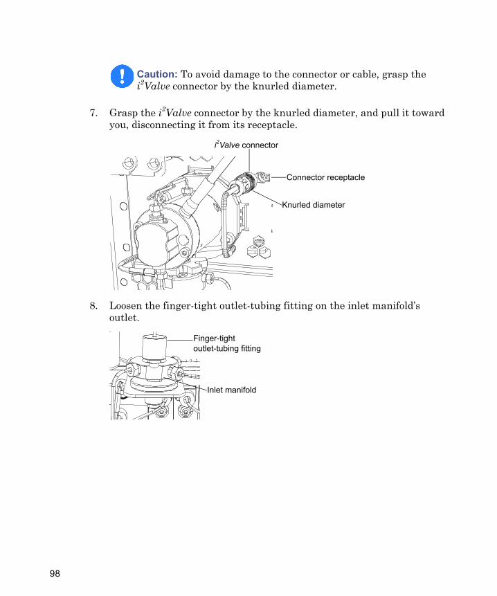
7. Grasp the i2Valve connector by the knurled diameter, and pull it toward you, disconnecting it from its receptacle.
8. Loosen the finger-tight outlet-tubing fitting on the inlet manifold’s outlet.
Caution: To avoid damage to the connector or cable, grasp the i2Valve connector by the knurled diameter.
i2Valve connector
Knurled diameter
Connector receptacle
Inlet manifold
Finger-tight outlet-tubing fitting
98
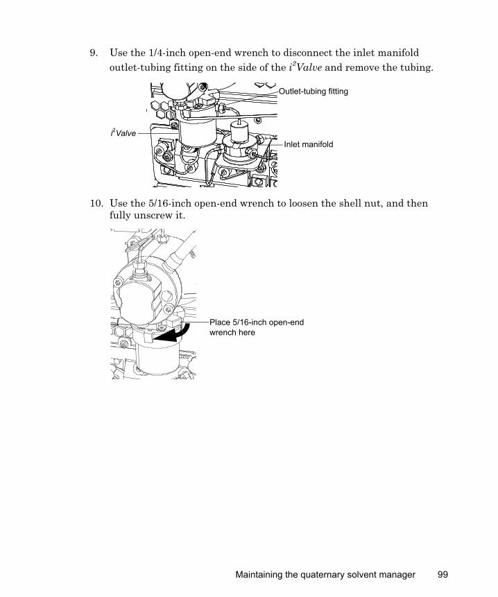
9. Use the 1/4-inch open-end wrench to disconnect the inlet manifold outlet-tubing fitting on the side of the i2Valve and remove the tubing.
10. Use the 5/16-inch open-end wrench to loosen the shell nut, and then fully unscrew it.
Outlet-tubing fitting
Inlet manifoldi2Valve
Place 5/16-inch open-end wrench here
Maintaining the quaternary solvent manager 99
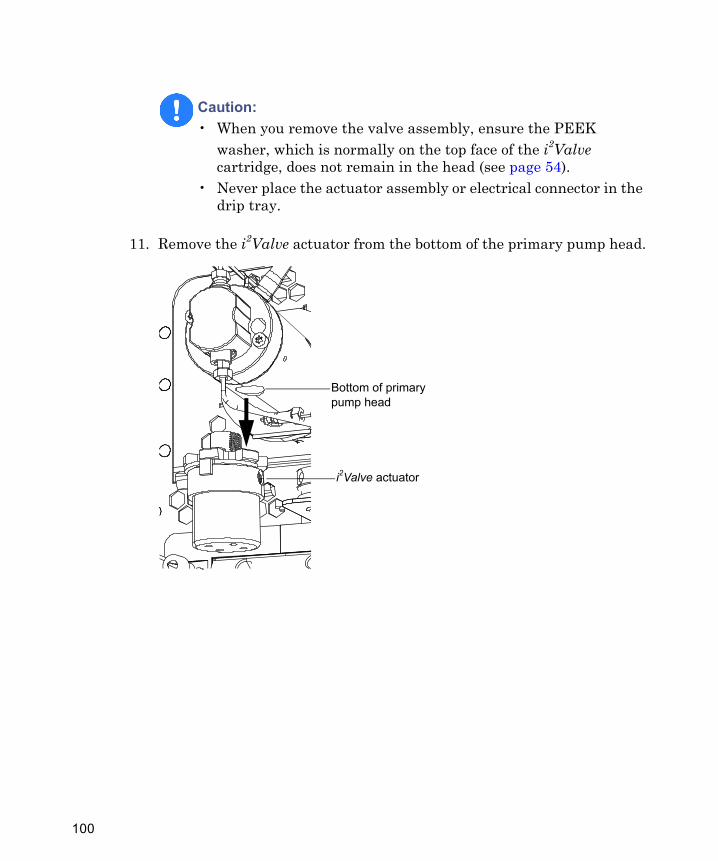
11. Remove the i2Valve actuator from the bottom of the primary pump head.
Caution: • When you remove the valve assembly, ensure the PEEK
washer, which is normally on the top face of the i2Valve cartridge, does not remain in the head (see page 54).
• Never place the actuator assembly or electrical connector in the drip tray.
Bottom of primary pump head
i2Valve actuator
100
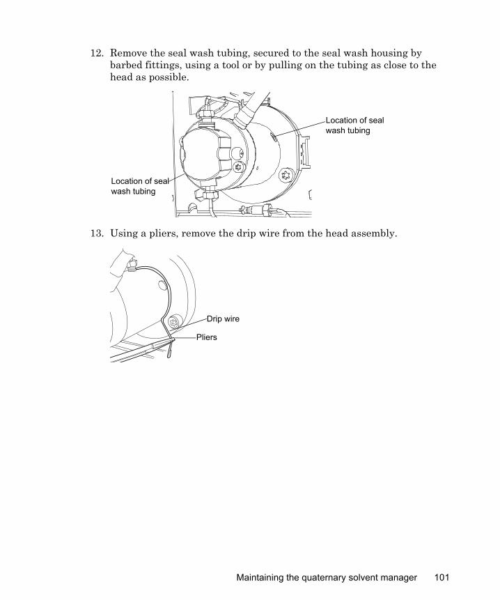
12. Remove the seal wash tubing, secured to the seal wash housing by barbed fittings, using a tool or by pulling on the tubing as close to the head as possible.
13. Using a pliers, remove the drip wire from the head assembly.
Location of seal wash tubing
Location of seal wash tubing
Drip wire
Pliers
Maintaining the quaternary solvent manager 101
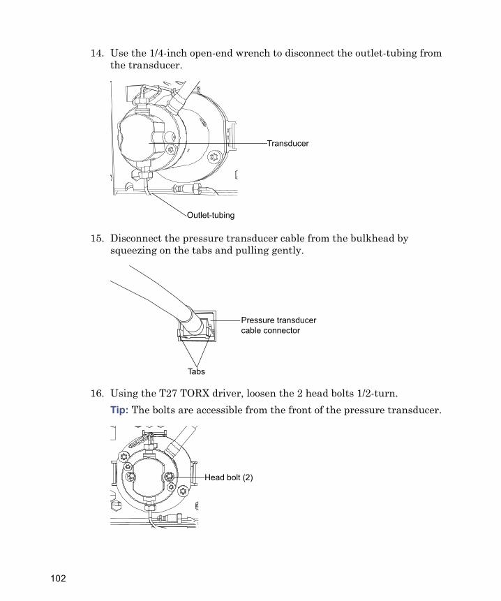
14. Use the 1/4-inch open-end wrench to disconnect the outlet-tubing from the transducer.
15. Disconnect the pressure transducer cable from the bulkhead by squeezing on the tabs and pulling gently.
16. Using the T27 TORX driver, loosen the 2 head bolts 1/2-turn.Tip: The bolts are accessible from the front of the pressure transducer.
Transducer
Outlet-tubing
Pressure transducer cable connector
Tabs
Head bolt (2)
102
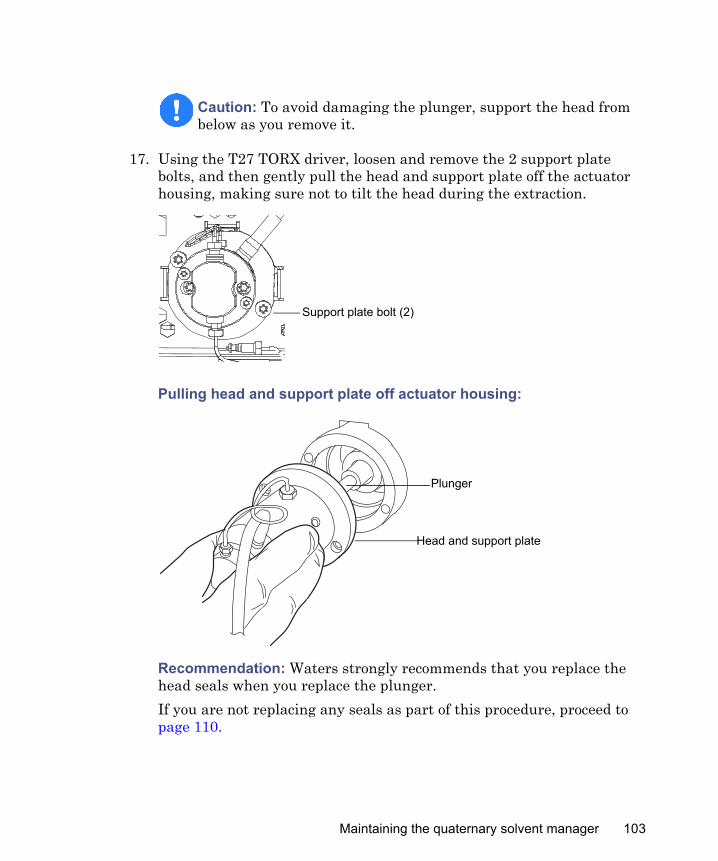
17. Using the T27 TORX driver, loosen and remove the 2 support plate bolts, and then gently pull the head and support plate off the actuator housing, making sure not to tilt the head during the extraction.
Pulling head and support plate off actuator housing:
Recommendation: Waters strongly recommends that you replace the head seals when you replace the plunger.If you are not replacing any seals as part of this procedure, proceed to page 110.
Caution: To avoid damaging the plunger, support the head from below as you remove it.
Support plate bolt (2)
Head and support plate
Plunger
Maintaining the quaternary solvent manager 103
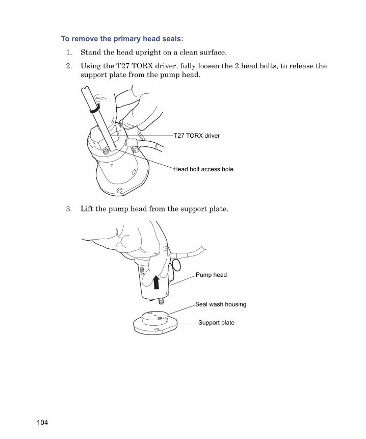
To remove the primary head seals:
1. Stand the head upright on a clean surface.
2. Using the T27 TORX driver, fully loosen the 2 head bolts, to release the support plate from the pump head.
3. Lift the pump head from the support plate.
T27 TORX driver
Head bolt access hole
Support plate
Pump head
Seal wash housing
104
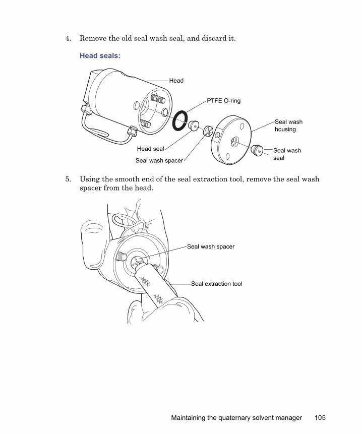
4. Remove the old seal wash seal, and discard it.
Head seals:
5. Using the smooth end of the seal extraction tool, remove the seal wash spacer from the head.
Seal wash housing
Seal wash seal
Head
PTFE O-ring
Head seal
Seal wash spacer
Seal extraction tool
Seal wash spacer
Maintaining the quaternary solvent manager 105

6. Taking care not to scratch any surfaces, screw the threaded end of the seal extraction tool into the head seal, and carefully withdraw the seal from the head.
Caution: To avoid scratching any metal surfaces, use care when screwing the threaded end of the seal extraction tool into the head seal.
TP03001
Seal extraction tool
Head seal
106

7. Use a sharp tool to remove the PTFE O-ring.
8. Lubricate the new PTFE O-ring with methanol, and press the O-ring into its seat with your thumbs.
Caution: To avoid scratching any metal surfaces, use care when using a sharp tool to remove the PTFE O-ring.
Sharp tool
PTFE O-ring
Maintaining the quaternary solvent manager 107

9. Lubricate the new head seal with methanol, and use the smooth end of the seal extraction tool to place it in the head.
TP02971
Head seal
Seal extraction tool
Head seal
Seal extraction tool
108

10. Center the new seal wash spacer over the head seal so that the cross-side faces upward.
11. Orient the seal wash housing so that the holes on its side align with the holes on the side of the head, and then guide it into place.
12. Install the new seal wash seal in the seal wash housing.
13. Place the support plate on top of the head.
Seal wash spacer with cross-side facing up
Head
Seal wash housing
Maintaining the quaternary solvent manager 109
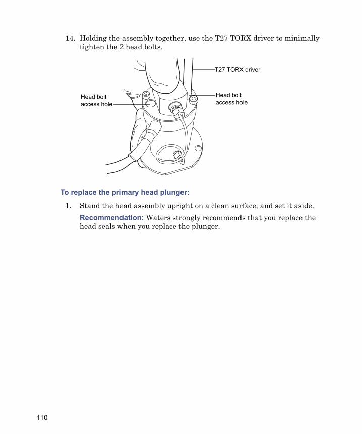
14. Holding the assembly together, use the T27 TORX driver to minimally tighten the 2 head bolts.
To replace the primary head plunger:
1. Stand the head assembly upright on a clean surface, and set it aside.Recommendation: Waters strongly recommends that you replace the head seals when you replace the plunger.
T27 TORX driver
Head bolt access hole
Head bolt access hole
110

2. Use the recessed side of the plunger removal tool to apply pressure to both sides of the release collar, and then remove the old plunger.
3. While applying pressure to the release collar with the plunger removal tool, grasp the new plunger with a clean, lint-free cloth, and insert it.
4. Remove the plunger removal tool from the release collar.
5. Grasp the new plunger by its metal portion, and make sure the plunger is securely in place.
TP02990
Plunger removal tool
Plunger
Spring-loaded release collar
Recessed lip of plunger removal tool
Maintaining the quaternary solvent manager 111
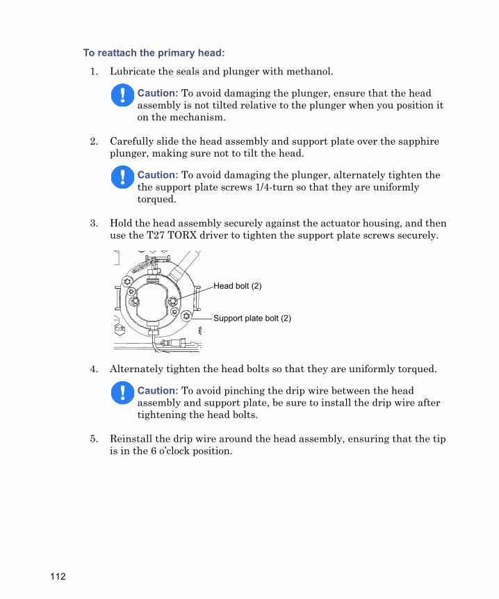
To reattach the primary head:
1. Lubricate the seals and plunger with methanol.
2. Carefully slide the head assembly and support plate over the sapphire plunger, making sure not to tilt the head.
3. Hold the head assembly securely against the actuator housing, and then use the T27 TORX driver to tighten the support plate screws securely.
4. Alternately tighten the head bolts so that they are uniformly torqued.
5. Reinstall the drip wire around the head assembly, ensuring that the tip is in the 6 o’clock position.
Caution: To avoid damaging the plunger, ensure that the head assembly is not tilted relative to the plunger when you position it on the mechanism.
Caution: To avoid damaging the plunger, alternately tighten the the support plate screws 1/4-turn so that they are uniformly torqued.
Caution: To avoid pinching the drip wire between the head assembly and support plate, be sure to install the drip wire after tightening the head bolts.
Support plate bolt (2)
Head bolt (2)
112
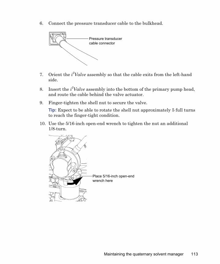
6. Connect the pressure transducer cable to the bulkhead.
7. Orient the i2Valve assembly so that the cable exits from the left-hand side.
8. Insert the i2Valve assembly into the bottom of the primary pump head, and route the cable behind the valve actuator.
9. Finger-tighten the shell nut to secure the valve.Tip: Expect to be able to rotate the shell nut approximately 5 full turns to reach the finger-tight condition.
10. Use the 5/16-inch open-end wrench to tighten the nut an additional 1/8-turn.
Pressure transducer cable connector
Place 5/16-inch open-end wrench here
Maintaining the quaternary solvent manager 113
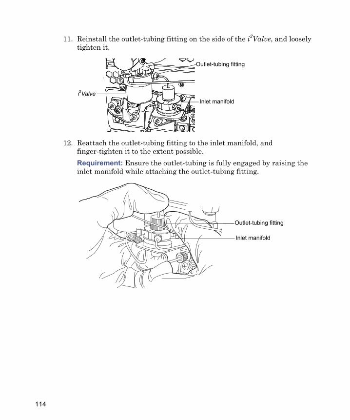
11. Reinstall the outlet-tubing fitting on the side of the i2Valve, and loosely tighten it.
12. Reattach the outlet-tubing fitting to the inlet manifold, and finger-tighten it to the extent possible.Requirement: Ensure the outlet-tubing is fully engaged by raising the inlet manifold while attaching the outlet-tubing fitting.
Outlet-tubing fitting
Inlet manifoldi2Valve
Outlet-tubing fitting
Inlet manifold
114
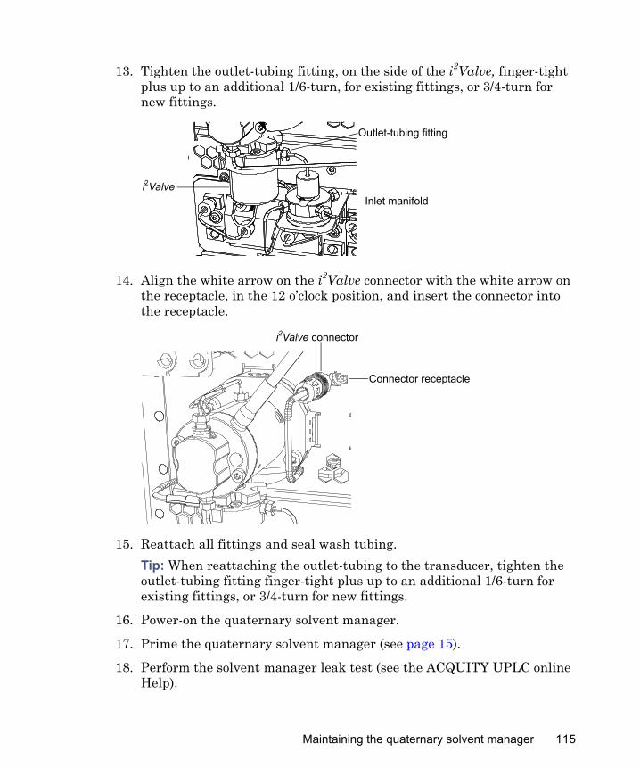
13. Tighten the outlet-tubing fitting, on the side of the i2Valve, finger-tight plus up to an additional 1/6-turn, for existing fittings, or 3/4-turn for new fittings.
14. Align the white arrow on the i2Valve connector with the white arrow on the receptacle, in the 12 o’clock position, and insert the connector into the receptacle.
15. Reattach all fittings and seal wash tubing.Tip: When reattaching the outlet-tubing to the transducer, tighten the outlet-tubing fitting finger-tight plus up to an additional 1/6-turn for existing fittings, or 3/4-turn for new fittings.
16. Power-on the quaternary solvent manager.
17. Prime the quaternary solvent manager (see page 15).
18. Perform the solvent manager leak test (see the ACQUITY UPLC online Help).
Outlet-tubing fitting
Inlet manifoldi2Valve
i2Valve connector
Connector receptacle
Maintaining the quaternary solvent manager 115
Tip: If the leak test results are not satisfactory, try pressurizing the head plunger seals to properly seat them. To pressurize the seals, perform one of these procedures:• Run the quaternary solvent manager at 96,527 kPa (965 bar, 14,000
psi) for a half-hour.• Run the leak test until results are satisfactory.
Replacing the accumulator head plunger
Required materials
• 1/4-inch open-end wrench • 5/16-inch open-end wrench• T27 TORX driver (startup kit)• Gloves: clean, powder-free, chemical-resistant• Head seal and seal wash spacer (recommended)• Methanol• Plunger removal tool• PTFE O-ring (recommended)• Replacement plunger• Seal extraction tool (recommended)• Seal wash seal (recommended)• Sharp tool (recommended)
Warning: To prevent injury, always observe Good Laboratory Practice when you handle solvents, change tubing, or operate the quaternary solvent manager. Consult the Material Safety Data Sheets regarding the solvents you use.
Caution: To prevent contamination, wear clean, chemical-resistant, powder-free gloves when replacing the plunger.
116
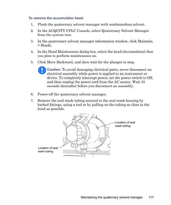
To remove the accumulator head:
1. Flush the quaternary solvent manager with nonhazardous solvent.
2. In the ACQUITY UPLC Console, select Quaternary Solvent Manager from the system tree.
3. In the quaternary solvent manager information window, click Maintain > Heads.
4. In the Head Maintenance dialog box, select the head (Accumulator) that you plan to perform maintenance on.
5. Click Move Backward, and then wait for the plunger to stop.
6. Power-off the quaternary solvent manager.
7. Remove the seal wash tubing secured to the seal wash housing by barbed fittings, using a tool or by pulling on the tubing as close to the head as possible.
Caution: To avoid damaging electrical parts, never disconnect an electrical assembly while power is applied to an instrument or device. To completely interrupt power, set the power switch to Off, and then unplug the power cord from the AC source. Wait 10 seconds thereafter before you disconnect an assembly.
Location of seal wash tubing
Location of seal wash tubing
Maintaining the quaternary solvent manager 117
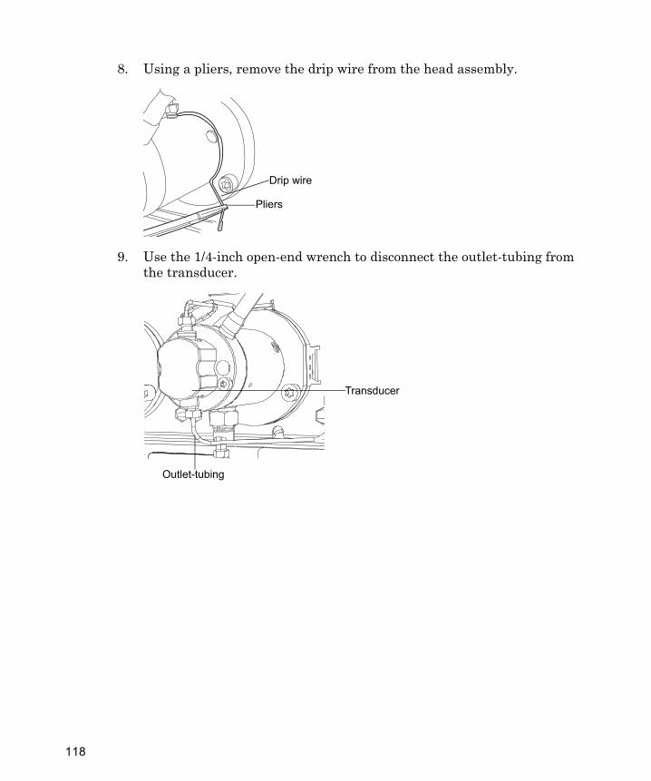
8. Using a pliers, remove the drip wire from the head assembly.
9. Use the 1/4-inch open-end wrench to disconnect the outlet-tubing from the transducer.
Drip wire
Pliers
Transducer
Outlet-tubing
118
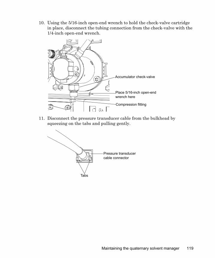
10. Using the 5/16-inch open-end wrench to hold the check-valve cartridge in place, disconnect the tubing connection from the check-valve with the 1/4-inch open-end wrench.
11. Disconnect the pressure transducer cable from the bulkhead by squeezing on the tabs and pulling gently.
Accumulator check-valve
Compression fitting
Place 5/16-inch open-end wrench here
Pressure transducer cable connector
Tabs
Maintaining the quaternary solvent manager 119
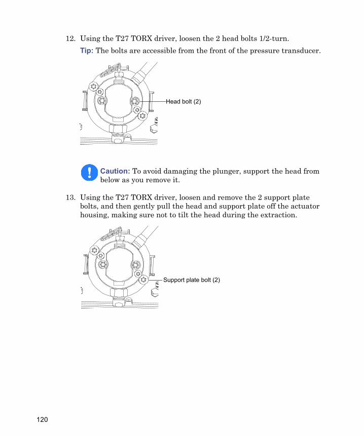
12. Using the T27 TORX driver, loosen the 2 head bolts 1/2-turn.Tip: The bolts are accessible from the front of the pressure transducer.
13. Using the T27 TORX driver, loosen and remove the 2 support plate bolts, and then gently pull the head and support plate off the actuator housing, making sure not to tilt the head during the extraction.
Caution: To avoid damaging the plunger, support the head from below as you remove it.
Head bolt (2)
Support plate bolt (2)
120
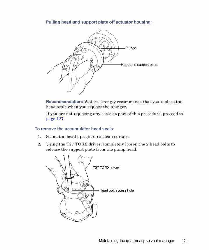
Pulling head and support plate off actuator housing:
Recommendation: Waters strongly recommends that you replace the head seals when you replace the plunger.If you are not replacing any seals as part of this procedure, proceed to page 127.
To remove the accumulator head seals:
1. Stand the head upright on a clean surface.
2. Using the T27 TORX driver, completely loosen the 2 head bolts to release the support plate from the pump head.
Head and support plate
Plunger
T27 TORX driver
Head bolt access hole
Maintaining the quaternary solvent manager 121
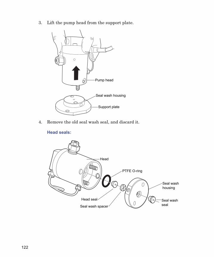
3. Lift the pump head from the support plate.
4. Remove the old seal wash seal, and discard it.
Head seals:
TP02987
Support plate
Pump head
Seal wash housing
Seal wash housing
Seal wash seal
Head
PTFE O-ring
Head seal
Seal wash spacer
122
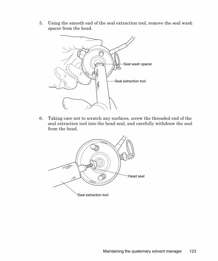
5. Using the smooth end of the seal extraction tool, remove the seal wash spacer from the head.
6. Taking care not to scratch any surfaces, screw the threaded end of the seal extraction tool into the head seal, and carefully withdraw the seal from the head.
Seal extraction tool
Seal wash spacer
TP03001
Seal extraction tool
Head seal
Maintaining the quaternary solvent manager 123
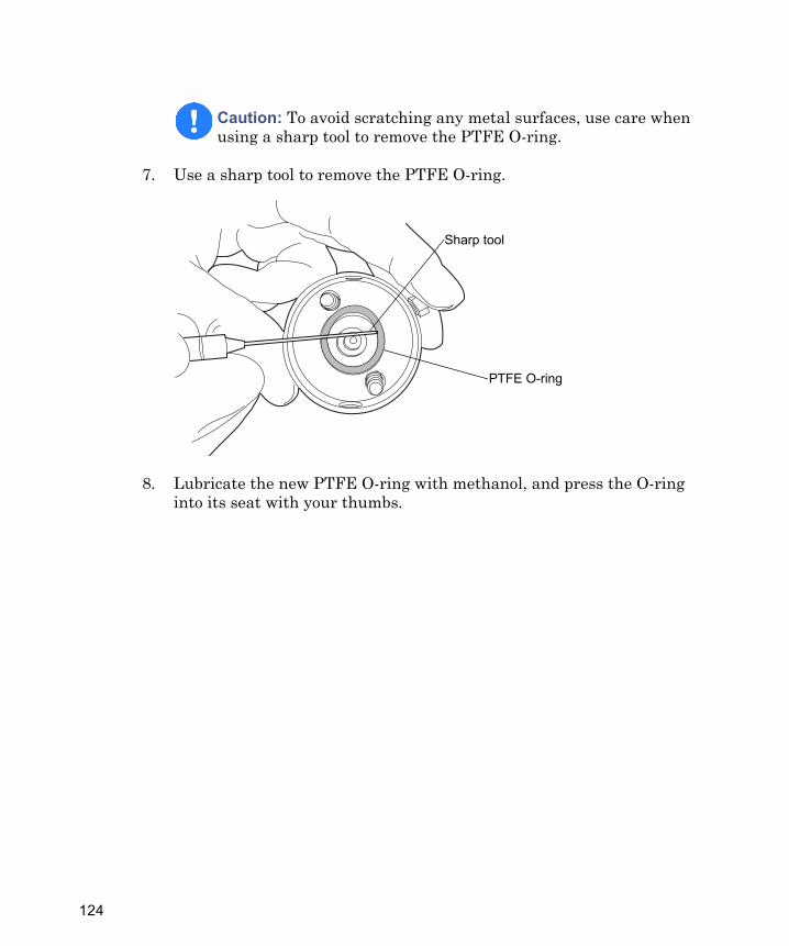
7. Use a sharp tool to remove the PTFE O-ring.
8. Lubricate the new PTFE O-ring with methanol, and press the O-ring into its seat with your thumbs.
Caution: To avoid scratching any metal surfaces, use care when using a sharp tool to remove the PTFE O-ring.
Sharp tool
PTFE O-ring
124
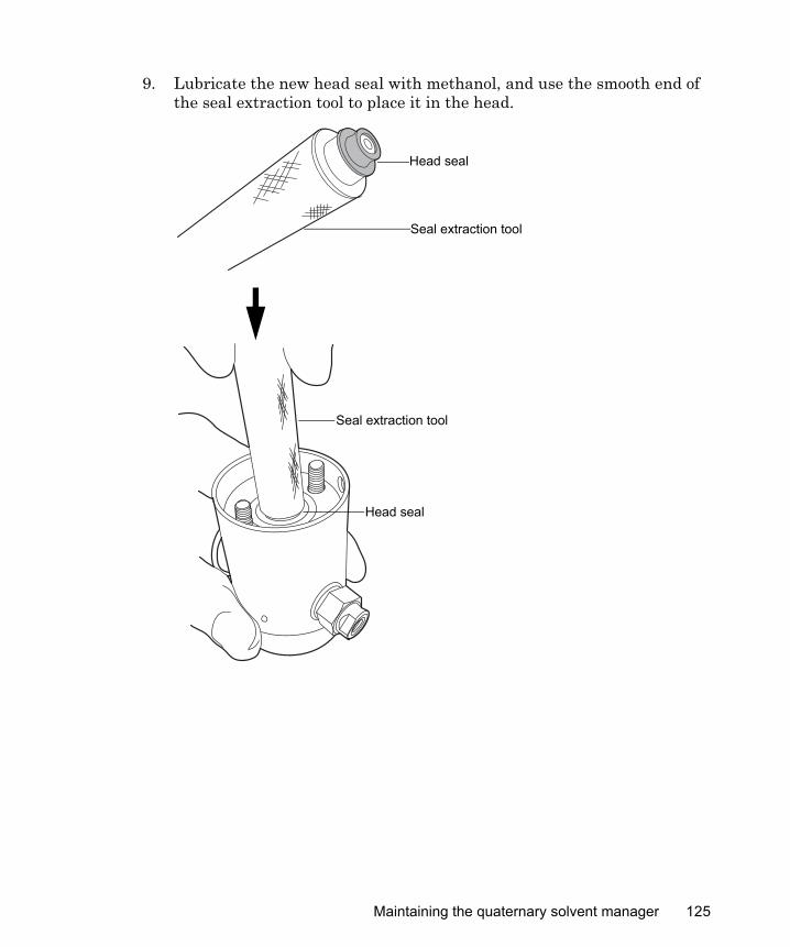
9. Lubricate the new head seal with methanol, and use the smooth end of the seal extraction tool to place it in the head.
Head seal
Seal extraction tool
TP02971
Head seal
Seal extraction tool
Maintaining the quaternary solvent manager 125
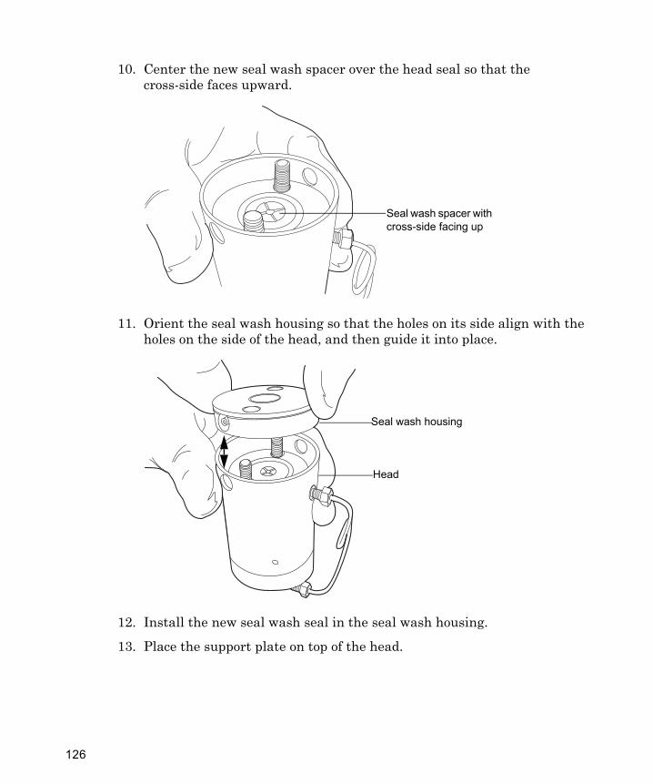
10. Center the new seal wash spacer over the head seal so that the cross-side faces upward.
11. Orient the seal wash housing so that the holes on its side align with the holes on the side of the head, and then guide it into place.
12. Install the new seal wash seal in the seal wash housing.
13. Place the support plate on top of the head.
Seal wash spacer with cross-side facing up
Head
Seal wash housing
126
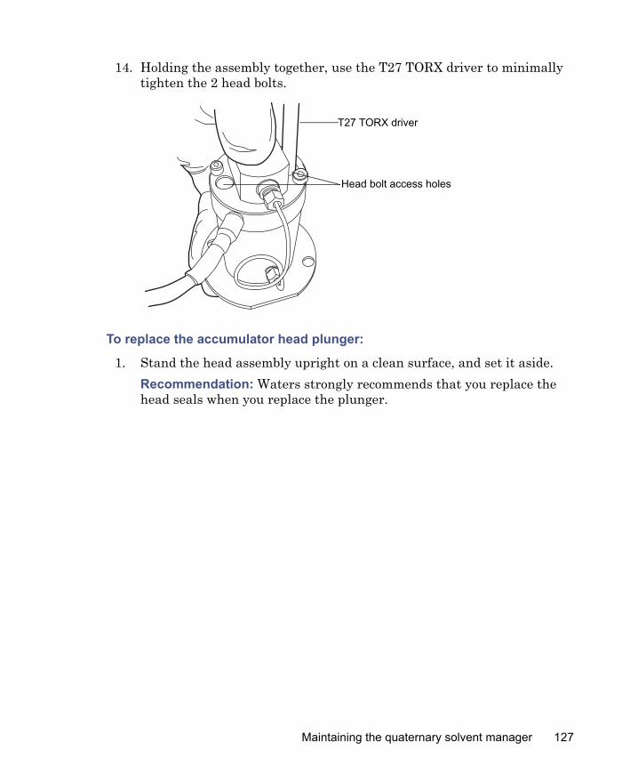
14. Holding the assembly together, use the T27 TORX driver to minimally tighten the 2 head bolts.
To replace the accumulator head plunger:
1. Stand the head assembly upright on a clean surface, and set it aside.Recommendation: Waters strongly recommends that you replace the head seals when you replace the plunger.
T27 TORX driver
Head bolt access holes
Maintaining the quaternary solvent manager 127
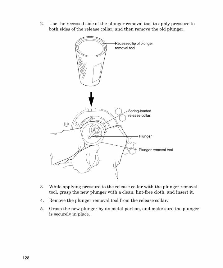
2. Use the recessed side of the plunger removal tool to apply pressure to both sides of the release collar, and then remove the old plunger.
3. While applying pressure to the release collar with the plunger removal tool, grasp the new plunger with a clean, lint-free cloth, and insert it.
4. Remove the plunger removal tool from the release collar.
5. Grasp the new plunger by its metal portion, and make sure the plunger is securely in place.
TP02990
Plunger removal tool
Plunger
Spring-loaded release collar
Recessed lip of plunger removal tool
128
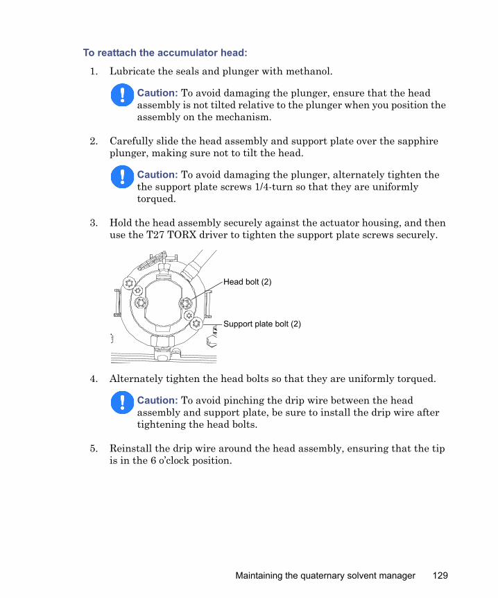
To reattach the accumulator head:
1. Lubricate the seals and plunger with methanol.
2. Carefully slide the head assembly and support plate over the sapphire plunger, making sure not to tilt the head.
3. Hold the head assembly securely against the actuator housing, and then use the T27 TORX driver to tighten the support plate screws securely.
4. Alternately tighten the head bolts so that they are uniformly torqued.
5. Reinstall the drip wire around the head assembly, ensuring that the tip is in the 6 o’clock position.
Caution: To avoid damaging the plunger, ensure that the head assembly is not tilted relative to the plunger when you position the assembly on the mechanism.
Caution: To avoid damaging the plunger, alternately tighten the the support plate screws 1/4-turn so that they are uniformly torqued.
Caution: To avoid pinching the drip wire between the head assembly and support plate, be sure to install the drip wire after tightening the head bolts.
Support plate bolt (2)
Head bolt (2)
Maintaining the quaternary solvent manager 129
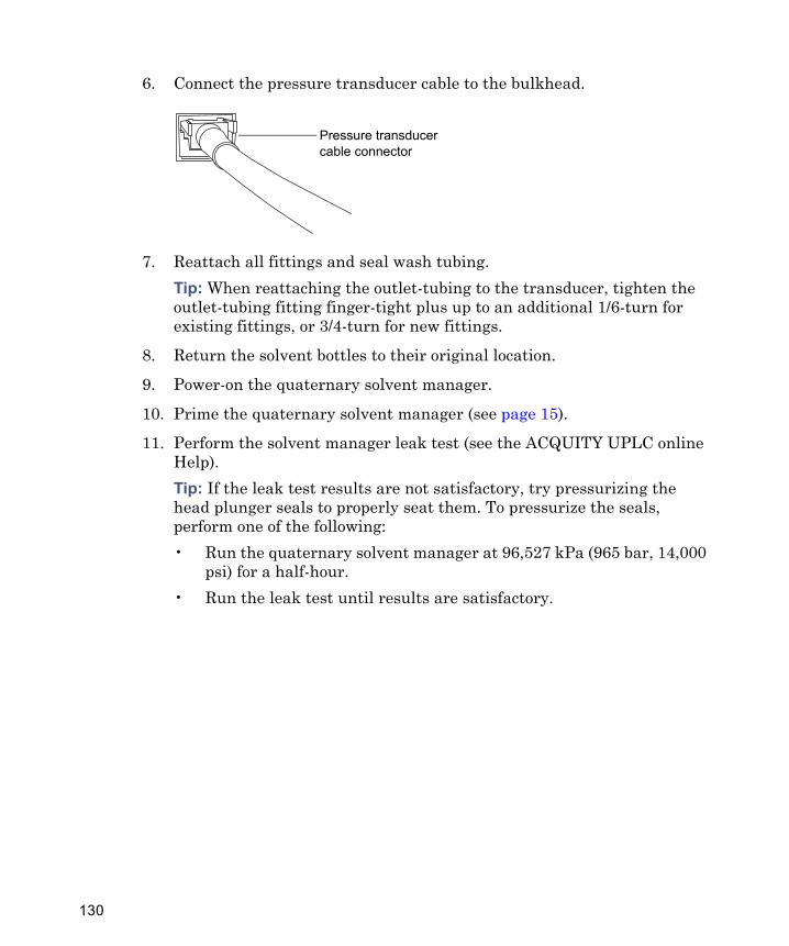
6. Connect the pressure transducer cable to the bulkhead.
7. Reattach all fittings and seal wash tubing.Tip: When reattaching the outlet-tubing to the transducer, tighten the outlet-tubing fitting finger-tight plus up to an additional 1/6-turn for existing fittings, or 3/4-turn for new fittings.
8. Return the solvent bottles to their original location.
9. Power-on the quaternary solvent manager.
10. Prime the quaternary solvent manager (see page 15).
11. Perform the solvent manager leak test (see the ACQUITY UPLC online Help). Tip: If the leak test results are not satisfactory, try pressurizing the head plunger seals to properly seat them. To pressurize the seals, perform one of the following:• Run the quaternary solvent manager at 96,527 kPa (965 bar, 14,000
psi) for a half-hour.• Run the leak test until results are satisfactory.
Pressure transducer cable connector
130
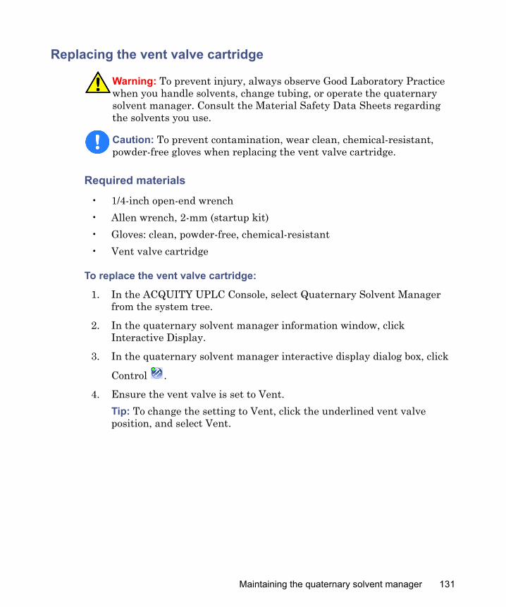
Replacing the vent valve cartridge
Required materials
• 1/4-inch open-end wrench • Allen wrench, 2-mm (startup kit)• Gloves: clean, powder-free, chemical-resistant• Vent valve cartridge
To replace the vent valve cartridge:
1. In the ACQUITY UPLC Console, select Quaternary Solvent Manager from the system tree.
2. In the quaternary solvent manager information window, click Interactive Display.
3. In the quaternary solvent manager interactive display dialog box, click
Control .
4. Ensure the vent valve is set to Vent.Tip: To change the setting to Vent, click the underlined vent valve position, and select Vent.
Warning: To prevent injury, always observe Good Laboratory Practice when you handle solvents, change tubing, or operate the quaternary solvent manager. Consult the Material Safety Data Sheets regarding the solvents you use.
Caution: To prevent contamination, wear clean, chemical-resistant, powder-free gloves when replacing the vent valve cartridge.
Maintaining the quaternary solvent manager 131
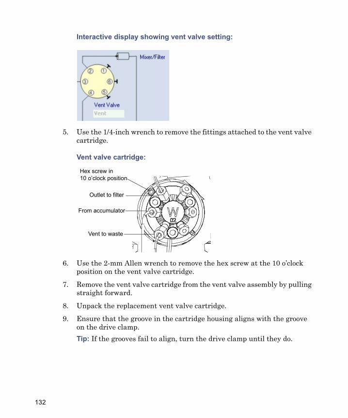
Interactive display showing vent valve setting:
5. Use the 1/4-inch wrench to remove the fittings attached to the vent valve cartridge.
Vent valve cartridge:
6. Use the 2-mm Allen wrench to remove the hex screw at the 10 o’clock position on the vent valve cartridge.
7. Remove the vent valve cartridge from the vent valve assembly by pulling straight forward.
8. Unpack the replacement vent valve cartridge.
9. Ensure that the groove in the cartridge housing aligns with the groove on the drive clamp.Tip: If the grooves fail to align, turn the drive clamp until they do.
From accumulator
Vent to waste
Outlet to filter
Hex screw in10 o’clock position
132
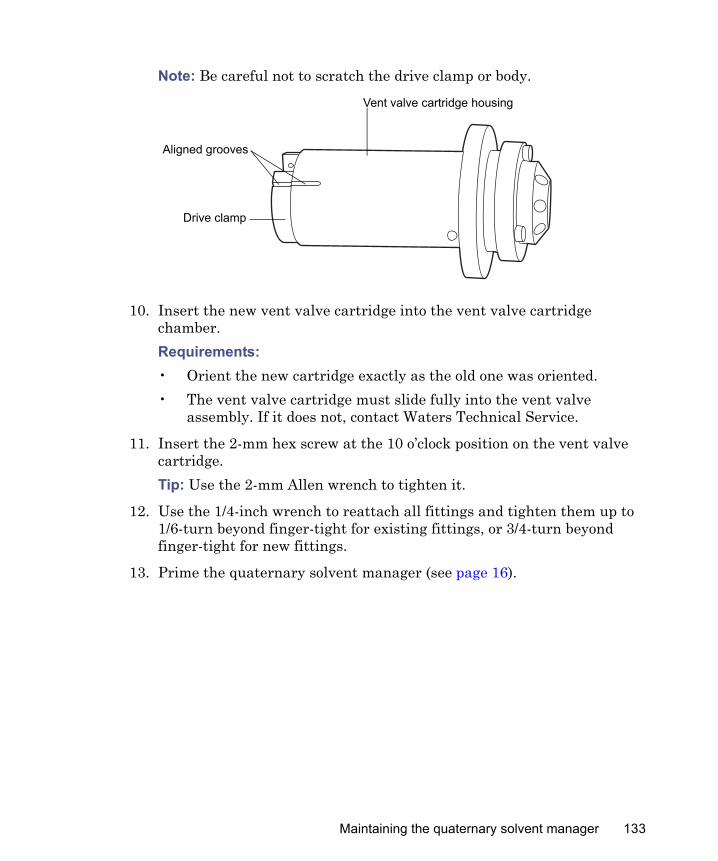
Note: Be careful not to scratch the drive clamp or body.
10. Insert the new vent valve cartridge into the vent valve cartridge chamber.Requirements: • Orient the new cartridge exactly as the old one was oriented.• The vent valve cartridge must slide fully into the vent valve
assembly. If it does not, contact Waters Technical Service.
11. Insert the 2-mm hex screw at the 10 o’clock position on the vent valve cartridge.Tip: Use the 2-mm Allen wrench to tighten it.
12. Use the 1/4-inch wrench to reattach all fittings and tighten them up to 1/6-turn beyond finger-tight for existing fittings, or 3/4-turn beyond finger-tight for new fittings.
13. Prime the quaternary solvent manager (see page 16).
Drive clamp
Aligned grooves
Vent valve cartridge housing
Maintaining the quaternary solvent manager 133
Replacing the optional solvent selection valve cartridge
Required materials
• Allen wrench, 2-mm (startup kit)• Gloves: clean, powder-free, chemical-resistant• Solvent selection valve cartridge
To replace the optional solvent selection valve cartridge:
1. In the ACQUITY UPLC Console, select Quaternary Solvent Manager from the system tree.
2. Ensure the solvent selection valve is set to 6.
3. Move the solvent bottles to a location below the quaternary solvent manager.
Warning: To prevent injury, always observe Good Laboratory Practice when you handle solvents, change tubing, or operate the quaternary solvent manager. Consult the Material Safety Data Sheets regarding the solvents you use.
Caution: To prevent contamination, wear clean, chemical-resistant, powder-free gloves when replacing the solvent selection valve cartridge.
Warning: To avoid solvent spills, move the solvent bottles to a location below the quaternary solvent manager.
134
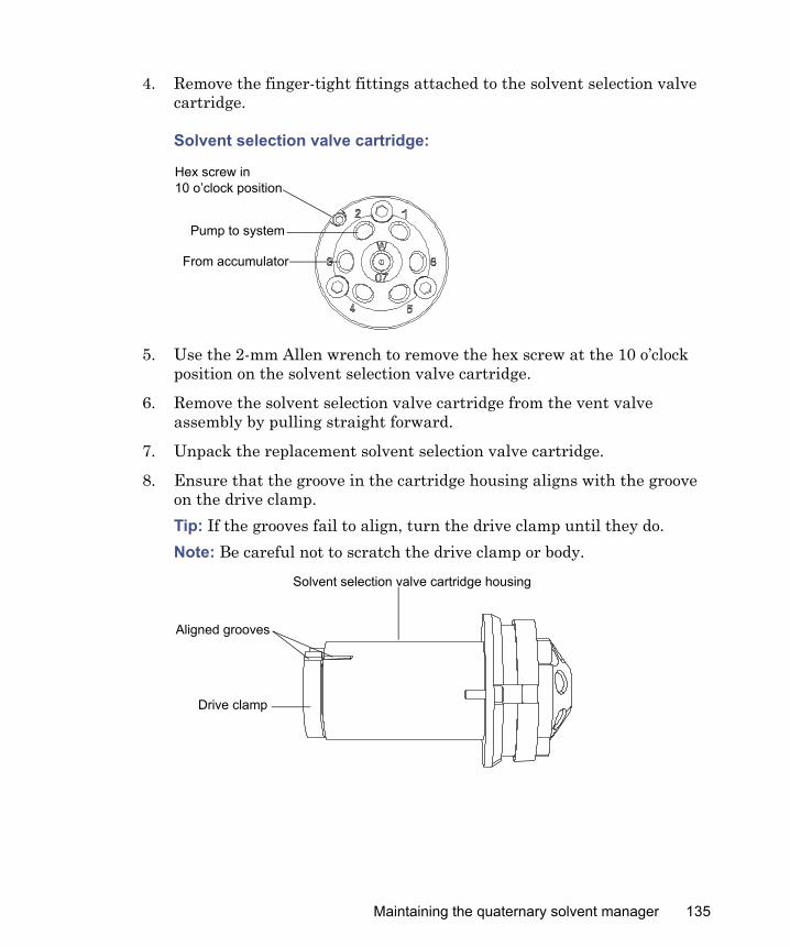
4. Remove the finger-tight fittings attached to the solvent selection valve cartridge.
Solvent selection valve cartridge:
5. Use the 2-mm Allen wrench to remove the hex screw at the 10 o’clock position on the solvent selection valve cartridge.
6. Remove the solvent selection valve cartridge from the vent valve assembly by pulling straight forward.
7. Unpack the replacement solvent selection valve cartridge.
8. Ensure that the groove in the cartridge housing aligns with the groove on the drive clamp.Tip: If the grooves fail to align, turn the drive clamp until they do.Note: Be careful not to scratch the drive clamp or body.
From accumulator
Pump to system
Hex screw in10 o’clock position
Drive clamp
Aligned grooves
Solvent selection valve cartridge housing
Maintaining the quaternary solvent manager 135
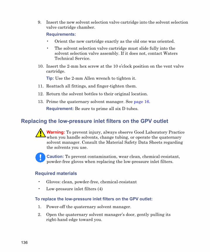
9. Insert the new solvent selection valve cartridge into the solvent selection valve cartridge chamber.Requirements:• Orient the new cartridge exactly as the old one was oriented.• The solvent selection valve cartridge must slide fully into the
solvent selection valve assembly. If it does not, contact Waters Technical Service.
10. Insert the 2-mm hex screw at the 10 o’clock position on the vent valve cartridge.Tip: Use the 2-mm Allen wrench to tighten it.
11. Reattach all fittings, and finger-tighten them.
12. Return the solvent bottles to their original location.
13. Prime the quaternary solvent manager. See page 16.Requirement: Be sure to prime all six D tubes.
Replacing the low-pressure inlet filters on the GPV outlet
Required materials
• Gloves: clean, powder-free, chemical-resistant• Low-pressure inlet filters (4)
To replace the low-pressure inlet filters on the GPV outlet:
1. Power-off the quaternary solvent manager.
2. Open the quaternary solvent manager’s door, gently pulling its right-hand edge toward you.
Warning: To prevent injury, always observe Good Laboratory Practice when you handle solvents, change tubing, or operate the quaternary solvent manager. Consult the Material Safety Data Sheets regarding the solvents you use.
Caution: To prevent contamination, wear clean, chemical-resistant, powder-free gloves when replacing the low-pressure inlet filters.
136
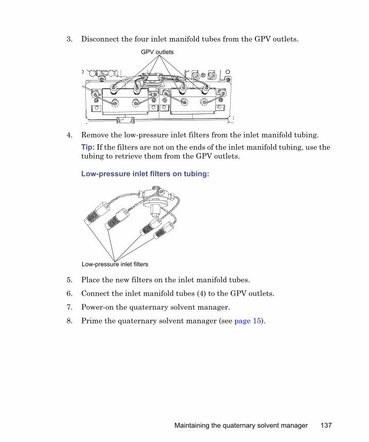
3. Disconnect the four inlet manifold tubes from the GPV outlets.
4. Remove the low-pressure inlet filters from the inlet manifold tubing.Tip: If the filters are not on the ends of the inlet manifold tubing, use the tubing to retrieve them from the GPV outlets.
Low-pressure inlet filters on tubing:
5. Place the new filters on the inlet manifold tubes.
6. Connect the inlet manifold tubes (4) to the GPV outlets.
7. Power-on the quaternary solvent manager.
8. Prime the quaternary solvent manager (see page 15).
GPV outlets
Low-pressure inlet filters
Maintaining the quaternary solvent manager 137
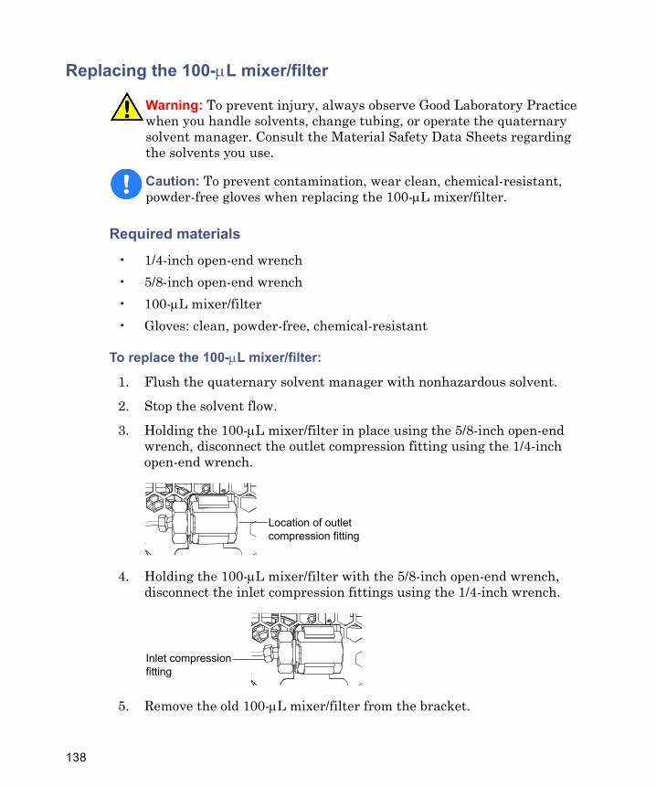
Replacing the 100-μL mixer/filter
Required materials
• 1/4-inch open-end wrench• 5/8-inch open-end wrench• 100-μL mixer/filter• Gloves: clean, powder-free, chemical-resistant
To replace the 100-μL mixer/filter:
1. Flush the quaternary solvent manager with nonhazardous solvent.
2. Stop the solvent flow.
3. Holding the 100-μL mixer/filter in place using the 5/8-inch open-end wrench, disconnect the outlet compression fitting using the 1/4-inch open-end wrench.
4. Holding the 100-μL mixer/filter with the 5/8-inch open-end wrench, disconnect the inlet compression fittings using the 1/4-inch wrench.
5. Remove the old 100-μL mixer/filter from the bracket.
Warning: To prevent injury, always observe Good Laboratory Practice when you handle solvents, change tubing, or operate the quaternary solvent manager. Consult the Material Safety Data Sheets regarding the solvents you use.
Caution: To prevent contamination, wear clean, chemical-resistant, powder-free gloves when replacing the 100-μL mixer/filter.
Location of outlet compression fitting
Inlet compression fitting
138
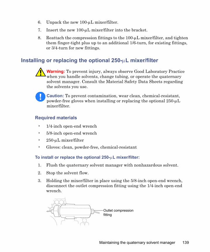
6. Unpack the new 100-μL mixer/filter.
7. Insert the new 100-μL mixer/filter into the bracket.
8. Reattach the compression fittings to the 100-μL mixer/filter, and tighten them finger-tight plus up to an additional 1/6-turn, for existing fittings, or 3/4-turn for new fittings.
Installing or replacing the optional 250-μL mixer/filter
Required materials
• 1/4-inch open-end wrench• 5/8-inch open-end wrench• 250-μL mixer/filter• Gloves: clean, powder-free, chemical-resistant
To install or replace the optional 250-μL mixer/filter:
1. Flush the quaternary solvent manager with nonhazardous solvent.
2. Stop the solvent flow.
3. Holding the mixer/filter in place using the 5/8-inch open-end wrench, disconnect the outlet compression fitting using the 1/4-inch open-end wrench.
Warning: To prevent injury, always observe Good Laboratory Practice when you handle solvents, change tubing, or operate the quaternary solvent manager. Consult the Material Safety Data Sheets regarding the solvents you use.
Caution: To prevent contamination, wear clean, chemical-resistant, powder-free gloves when installing or replacing the optional 250-μL mixer/filter.
Outlet compression fitting
Maintaining the quaternary solvent manager 139
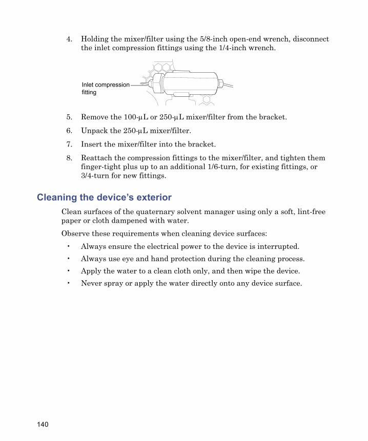
4. Holding the mixer/filter using the 5/8-inch open-end wrench, disconnect the inlet compression fittings using the 1/4-inch wrench.
5. Remove the 100-μL or 250-μL mixer/filter from the bracket.
6. Unpack the 250-μL mixer/filter.
7. Insert the mixer/filter into the bracket.
8. Reattach the compression fittings to the mixer/filter, and tighten them finger-tight plus up to an additional 1/6-turn, for existing fittings, or 3/4-turn for new fittings.
Cleaning the device’s exteriorClean surfaces of the quaternary solvent manager using only a soft, lint-free paper or cloth dampened with water.Observe these requirements when cleaning device surfaces:
• Always ensure the electrical power to the device is interrupted.• Always use eye and hand protection during the cleaning process.• Apply the water to a clean cloth only, and then wipe the device.• Never spray or apply the water directly onto any device surface.
Inlet compression fitting
140