Embed Size (px)
Citation preview
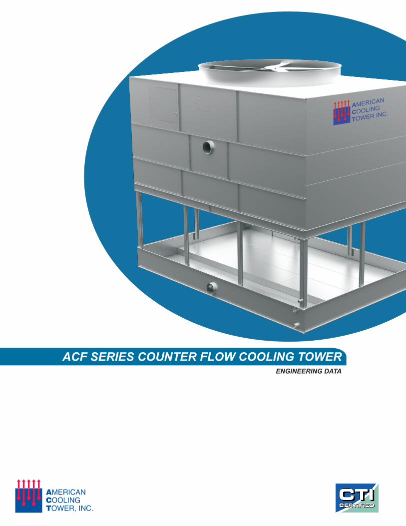
ACF SERIES COUNTER FLOW COOLING TOWERENGINEERING DATA
AMERICAN
COOLING
TOWER INC.

www.americancoolingtower.com Publication:1.0.1
AMERICAN COOLING TOWER INC.ACF SERIES FEATURES
OVERVIEW
CAPACITY
TECHNOLOGY & PARTNERSHIP
QUALITY CONTROL & WORKMANSHIP
SUSTAINABILTY
When American Cooling Tower began working on the ACFseries cooling tower design, we wanted to ensure that everyaspect of the tower design included the best componentsavailable in our industry. To achieve this, every majorcomponent supplier was deeply involved in the developmentand testing of the ACF cooling tower line to ensure that only thevery best materials and components were selected and utilizedwithin the design. Through this ongoing process we lookforward to the continual development of additional accessoriesand products to provide additional enhancement to the ACFseries line.
The ACF series induced draft counter flow cooling tower isAmerican Cooling Tower's factory assembled cooling towersystem which offers clients with a wide range of capacities andsizes to help accommodate your project needs.
The ACF series cooling tower line provides 86 unique models,all of which are CTI STD-201 certified. Nominal tonnage ranges from 97 to 1043 tons of cooling capacity.
For more than 25 years, American Cooling Tower has been involved in the cooling tower industry by providing a wide range of services and products to customers throughout the United States. Over this time, American Cooling Tower has developed a stringent in house quality control program to closely monitor production and quality of workmanship from start to finish. Through our Total Quality Management system American Cooling Tower monitors and records all aspects of our production process from raw material acquisition thru packaging of completed units for shipping.
As all manufacturers have continued to strive tomeet growing demands for utilizing sustainableand recycled materials, American CoolingTower is pleased that the current ACF seriescooling tower is comprised of more than 65%recycled materials.

www.americancoolingtower.com Publication:1.0.1
AMERICAN COOLING TOWER INC.COMPONENTS
- Premium Efficienct Cooling Tower Duty Fan MotorsIP55 construction and in accordance with MG1 part 31inverter duty rating.
- Marine grade axial fan assemblies with stainless steel 316 hardware and resilant mounting system which eliminatesalmost all resonant frequencies.
- Heavy Duty L10 100,000 hour bearings
- Solid banded belt drive systems
- Adjustable motor bases
- External lube lines for ease of maintenance
- 5 year mechanical warranty
- PVC header and lateral system
- Removable and cleanable
- Low pressure non-clogging spray nozzles - Will not rust or corrode- Long service life and easy to maintain.
- Low pump head requirements
FILL MEDIA- Flame Spread rating of 5 per ASTM E84-77a
- PVC mechanical assembly fill media
- Resistant to rot, decay, and biological attack
- High performance alternating tip design
- 140oF continous operating condition - Manufactured in accordance with CTI STD-136 - Stainless Steel 304 or 316 construction options
- SPDT & DPDT Vibration switchesDRIFT ELIMINATORS - Gear driven mechanical systems
- Cellular PVC design - Electronic make-up water assemblies- Multi-pass configuration - Variable Frequency Drives- 0.001% drift loss rates - Fully customizable control panels- Low pressure drop for better fan performance - Spring isolator rail mounting systems- Flame spread rating of 5 per ASTM E84-77a - Sand Filter and Vortex Separator systems
- Holding tanks for remote sump applications- Sound attenuation for low noise applications- Industrial liner option for maximum corrosion protection- Service platform and ladder systems
Additional accessories and options are available uponrequest. Contact your representative or call AmericanCooling Tower for more information.
FILL MEDIA AND DRIFT ELIMINATORS
MECHANICAL SYSTEM
DISTRIBUTION SYSTEM
ACCESSORIES AND OPTIONS
www.americancoolingtower.com Publication: 1.0.1
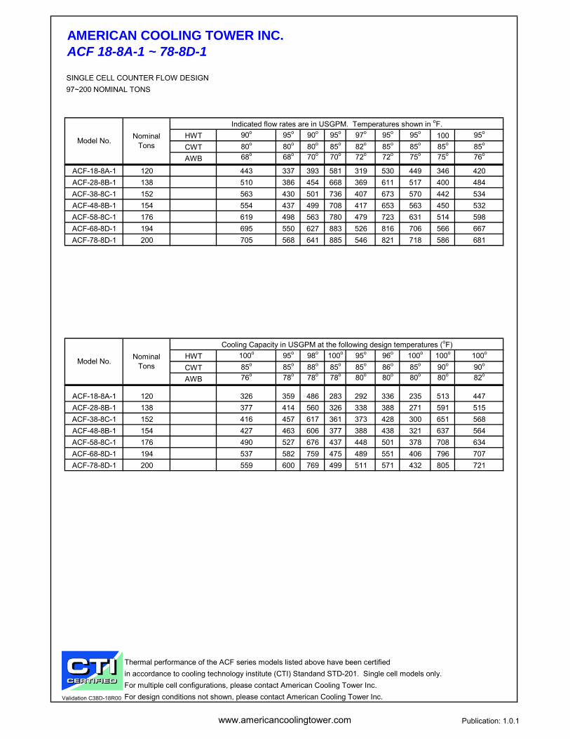
AMERICAN COOLING TOWER INC.ACF 18-8A-1 ~ 78-8D-1
SINGLE CELL COUNTER FLOW DESIGN97~200 NOMINAL TONS
HWT 90o 95o 90o 95o 97o 95o 95o 100 95o
CWT 80o 80o 80o 85o 82o 85o 85o 85o 85o
AWB 68o 68o 70o 70o 72o 72o 75o 75o 76o
ACF-18-8A-1 120 443 337 393 581 319 530 449 346 420ACF-28-8B-1 138 510 386 454 668 369 611 517 400 484ACF-38-8C-1 152 563 430 501 736 407 673 570 442 534ACF-48-8B-1 154 554 437 499 708 417 653 563 450 532ACF-58-8C-1 176 619 498 563 780 479 723 631 514 598ACF-68-8D-1 194 695 550 627 883 526 816 706 566 667ACF-78-8D-1 200 705 568 641 885 546 821 718 586 681
HWT 100o 95o 98o 100o 95o 96o 100o 100o 100o
CWT 85o 85o 88o 85o 85o 86o 85o 90o 90o
AWB 76o 78o 78o 78o 80o 80o 80o 80o 82o
ACF-18-8A-1 120 326 359 486 283 292 336 235 513 447ACF-28-8B-1 138 377 414 560 326 338 388 271 591 515ACF-38-8C-1 152 416 457 617 361 373 428 300 651 568ACF-48-8B-1 154 427 463 606 377 388 438 321 637 564ACF-58-8C-1 176 490 527 676 437 448 501 378 708 634ACF-68-8D-1 194 537 582 759 475 489 551 406 796 707ACF-78-8D-1 200 559 600 769 499 511 571 432 805 721
Thermal performance of the ACF series models listed above have been certified in accordance to cooling technology institute (CTI) Standand STD-201. Single cell models only.For multiple cell configurations, please contact American Cooling Tower Inc.
Validation C38D-18R00 For design conditions not shown, please contact American Cooling Tower Inc.
Model No. Nominal Tons
Indicated flow rates are in USGPM. Temperatures shown in oF.
Model No. Nominal Tons
Cooling Capacity in USGPM at the following design temperatures (oF)

www.americancoolingtower.com Publication: 1.0.1
AMERICAN COOLING TOWER INC.ACF 18-8A-1 ~ 78-8D-1
SINGLE CELL COUNTER FLOW DESIGN97 ~ 200 NOMINAL TONS
M - Denotes motor location
Shipping Operating Length (L) Width (W) Height (H)
ACF-18-8A-1 5 37000 3350 5820 8' 8' 6" 10'ACF-28-8B-1 7.5 40000 3390 5860 8' 8' 6" 10'ACF-38-8C-1 10 43000 3400 5890 8' 8' 6" 10'ACF-48-8B-1 7.5 37500 3620 6090 8' 8' 6" 11'ACF-58-8C-1 10 39000 3930 6400 8' 8' 6" 12'ACF-68-8D-1 15 44500 3720 6180 8' 8' 6" 11'ACF-78-8D-1 15 43100 3990 6460 8' 8' 6" 12'
Above drawings are for reference only.Inlet & Outlet connections are grooved for mechanical coupling.Dimensions and weights are subject to change without notification.Units are shipped factory assembled in two sections. Final assembly required by installer.
DimensionsModel No. Fan Motor
(HP)Air Flow (CFM)
Weight
ACCESSDOOR
6” INLET
W
6” OUTLET3” DRAIN
3” OVERFLOW
3”
L
H
2” MAKE-UP
ACCESS DOOR M
WL
www.americancoolingtower.com Publication: 1.0.1
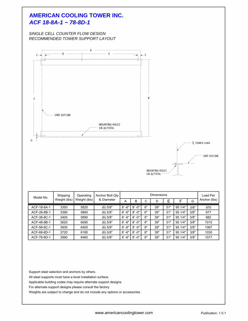
AMERICAN COOLING TOWER INC.ACF 18-8A-1 ~ 78-8D-1
SINGLE CELL COUNTER FLOW DESIGNRECOMMENDED TOWER SUPPORT LAYOUT
A B C D E F G
ACF-18-8A-1 3350 5820 (6) 5/8" 8' -6" 8' -0" 6" 39" 51" 95 1/4" 3/8" 970ACF-28-8B-1 3390 5860 (6) 5/8" 8' -6" 8' -0" 6" 39" 51" 95 1/4" 3/8" 977ACF-38-8C-1 3400 5890 (6) 5/8" 8' -6" 8' -0" 6" 39" 51" 95 1/4" 3/8" 982ACF-48-8B-1 3620 6090 (6) 5/8" 8' -6" 8' -0" 6" 39" 51" 95 1/4" 3/8" 1015ACF-58-8C-1 3930 6400 (6) 5/8" 8' -6" 8' -0" 6" 39" 51" 95 1/4" 3/8" 1067ACF-68-8D-1 3720 6180 (6) 5/8" 8' -6" 8' -0" 6" 39" 51" 95 1/4" 3/8" 1030ACF-78-8D-1 3990 6460 (6) 5/8" 8' -6" 8' -0" 6" 39" 51" 95 1/4" 3/8" 1077
Support steel selection and anchors by others.All steel supports must have a level installation surface. Applicable building codes may require alternate support designs. For alternate support designs please consult the factory. Weights are subject to change and do not include any options or accessories.
Model No. Load Per Anchor (lbs)
Shipping Weight (lbs)
Operating Weight (lbs)
Anchor Bolt Qty & Diameter
Dimensions
CL
MOUNTING HOLESSIX (6) TOTAL
UNIT OUTLINE
TOWER LOAD
C CD EA
G
F B
UNIT OUTLINE
MOUNTING HOLESSIX (6) TOTAL
www.americancoolingtower.com Publication: 1.0.1
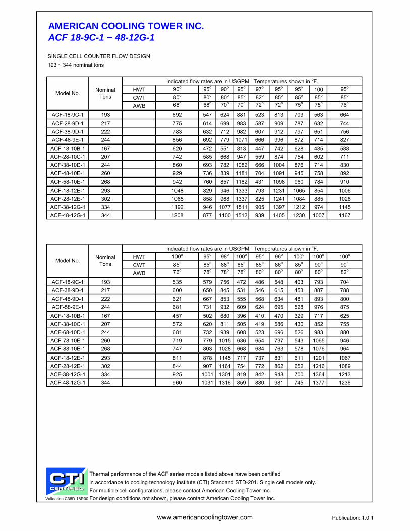
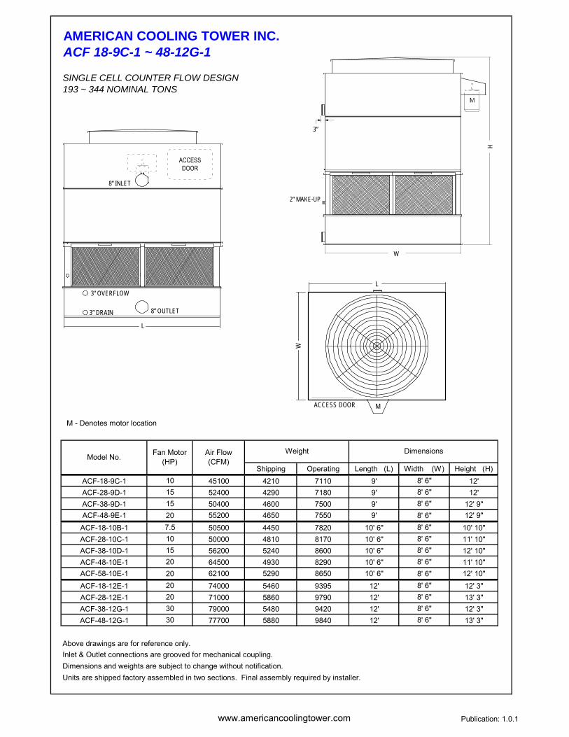
AMERICAN COOLING TOWER INC.ACF 18-9C-1 ~ 48-12G-1
SINGLE CELL COUNTER FLOW DESIGN193 ~ 344 nominal tons
HWT 90o 95o 90o 95o 97o 95o 95o 100 95o
CWT 80o 80o 80o 85o 82o 85o 85o 85o 85o
AWB 68o 68o 70o 70o 72o 72o 75o 75o 76o
ACF-18-9C-1 193 692 547 624 881 523 813 703 563 664ACF-28-9D-1 217 775 614 699 983 587 909 787 632 744ACF-38-9D-1 222 783 632 712 982 607 912 797 651 756ACF-48-9E-1 244 856 692 779 1071 666 996 872 714 827
ACF-18-10B-1 167 620 472 551 813 447 742 628 485 588ACF-28-10C-1 207 742 585 668 947 559 874 754 602 711ACF-38-10D-1 244 860 693 782 1082 666 1004 876 714 830ACF-48-10E-1 260 929 736 839 1181 704 1091 945 758 892ACF-58-10E-1 268 942 760 857 1182 431 1098 960 784 910ACF-18-12E-1 293 1048 829 946 1333 793 1231 1065 854 1006ACF-28-12E-1 302 1065 858 968 1337 825 1241 1084 885 1028ACF-38-12G-1 334 1192 946 1077 1511 905 1397 1212 974 1145ACF-48-12G-1 344 1208 877 1100 1512 939 1405 1230 1007 1167
HWT 100o 95o 98o 100o 95o 96o 100o 100o 100o
CWT 85o 85o 88o 85o 85o 86o 85o 90o 90o
AWB 76o 78o 78o 78o 80o 80o 80o 80o 82o
ACF-18-9C-1 193 535 579 756 472 486 548 403 793 704ACF-38-9D-1 217 600 650 845 531 546 615 453 887 788ACF-48-9D-1 222 621 667 853 555 568 634 481 893 800ACF-58-9E-1 244 681 731 932 609 624 695 528 976 875
ACF-18-10B-1 167 457 502 680 396 410 470 329 717 625ACF-38-10C-1 207 572 620 811 505 419 586 430 852 755ACF-68-10D-1 244 681 732 939 608 523 696 526 983 880ACF-78-10E-1 260 719 779 1015 636 654 737 543 1065 946ACF-88-10E-1 268 747 803 1028 668 684 763 578 1076 964ACF-18-12E-1 293 811 878 1145 717 737 831 611 1201 1067ACF-28-12E-1 302 844 907 1161 754 772 862 652 1216 1089ACF-38-12G-1 334 925 1001 1301 819 842 948 700 1364 1213ACF-48-12G-1 344 960 1031 1316 859 880 981 745 1377 1236
Thermal performance of the ACF series models listed above have been certified in accordance to cooling technology institute (CTI) Standand STD-201. Single cell models only.For multiple cell configurations, please contact American Cooling Tower Inc.
Validation C38D-18R00 For design conditions not shown, please contact American Cooling Tower Inc.
Model No. Nominal Tons
Indicated flow rates are in USGPM. Temperatures shown in oF.
Model No. Nominal Tons
Indicated flow rates are in USGPM. Temperatures shown in oF.
www.americancoolingtower.com Publication: 1.0.1
AMERICAN COOLING TOWER INC.ACF 18-9C-1 ~ 48-12G-1
SINGLE CELL COUNTER FLOW DESIGN193 ~ 344 NOMINAL TONS
M - Denotes motor location
Shipping Operating Length (L) Width (W) Height (H)ACF-18-9C-1 10 45100 4210 7110 9' 8' 6" 12'ACF-28-9D-1 15 52400 4290 7180 9' 8' 6" 12'ACF-38-9D-1 15 50400 4600 7500 9' 8' 6" 12' 9"ACF-48-9E-1 20 55200 4650 7550 9' 8' 6" 12' 9"
ACF-18-10B-1 7.5 50500 4450 7820 10' 6" 8' 6" 10' 10"ACF-28-10C-1 10 50000 4810 8170 10' 6" 8' 6" 11' 10"ACF-38-10D-1 15 56200 5240 8600 10' 6" 8' 6" 12' 10"ACF-48-10E-1 20 64500 4930 8290 10' 6" 8' 6" 11' 10"ACF-58-10E-1 20 62100 5290 8650 10' 6" 8' 6" 12' 10"ACF-18-12E-1 20 74000 5460 9395 12' 8' 6" 12' 3"ACF-28-12E-1 20 71000 5860 9790 12' 8' 6" 13' 3"ACF-38-12G-1 30 79000 5480 9420 12' 8' 6" 12' 3"ACF-48-12G-1 30 77700 5880 9840 12' 8' 6" 13' 3"
Above drawings are for reference only.Inlet & Outlet connections are grooved for mechanical coupling.Dimensions and weights are subject to change without notification.Units are shipped factory assembled in two sections. Final assembly required by installer.
DimensionsModel No. Fan Motor
(HP)Air Flow (CFM)
Weight
L
8” INLET
8” OUTLET3” DRAIN
3” OVERFLOW
3”
W
H
2” MAKE-UP
ACCESS DOOR M
L
W
www.americancoolingtower.com Publication: 1.0.1
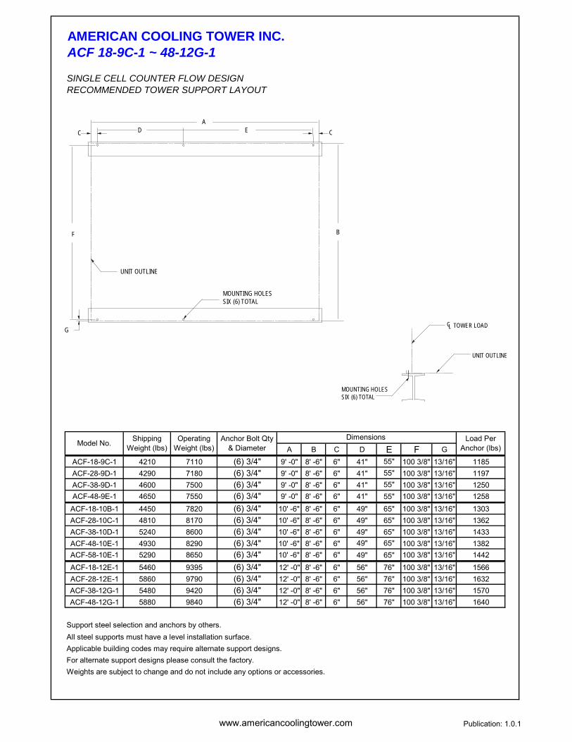
AMERICAN COOLING TOWER INC.ACF 18-9C-1 ~ 48-12G-1
SINGLE CELL COUNTER FLOW DESIGNRECOMMENDED TOWER SUPPORT LAYOUT
A B C D E F GACF-18-9C-1 4210 7110 (6) 3/4" 9' -0" 8' -6" 6" 41" 55" 100 3/8" 13/16" 1185ACF-28-9D-1 4290 7180 (6) 3/4" 9' -0" 8' -6" 6" 41" 55" 100 3/8" 13/16" 1197ACF-38-9D-1 4600 7500 (6) 3/4" 9' -0" 8' -6" 6" 41" 55" 100 3/8" 13/16" 1250ACF-48-9E-1 4650 7550 (6) 3/4" 9' -0" 8' -6" 6" 41" 55" 100 3/8" 13/16" 1258
ACF-18-10B-1 4450 7820 (6) 3/4" 10' -6" 8' -6" 6" 49" 65" 100 3/8" 13/16" 1303ACF-28-10C-1 4810 8170 (6) 3/4" 10' -6" 8' -6" 6" 49" 65" 100 3/8" 13/16" 1362ACF-38-10D-1 5240 8600 (6) 3/4" 10' -6" 8' -6" 6" 49" 65" 100 3/8" 13/16" 1433ACF-48-10E-1 4930 8290 (6) 3/4" 10' -6" 8' -6" 6" 49" 65" 100 3/8" 13/16" 1382ACF-58-10E-1 5290 8650 (6) 3/4" 10' -6" 8' -6" 6" 49" 65" 100 3/8" 13/16" 1442ACF-18-12E-1 5460 9395 (6) 3/4" 12' -0" 8' -6" 6" 56" 76" 100 3/8" 13/16" 1566ACF-28-12E-1 5860 9790 (6) 3/4" 12' -0" 8' -6" 6" 56" 76" 100 3/8" 13/16" 1632ACF-38-12G-1 5480 9420 (6) 3/4" 12' -0" 8' -6" 6" 56" 76" 100 3/8" 13/16" 1570ACF-48-12G-1 5880 9840 (6) 3/4" 12' -0" 8' -6" 6" 56" 76" 100 3/8" 13/16" 1640
Support steel selection and anchors by others.All steel supports must have a level installation surface. Applicable building codes may require alternate support designs. For alternate support designs please consult the factory. Weights are subject to change and do not include any options or accessories.
Model No. Shipping Weight (lbs)
Operating Weight (lbs)
Anchor Bolt Qty & Diameter
Dimensions Load Per Anchor (lbs)
CL
MOUNTING HOLESSIX (6) TOTAL
UNIT OUTLINE
TOWER LOAD
C CD EA
G
F B
UNIT OUTLINE
MOUNTING HOLESSIX (6) TOTAL

www.americancoolingtower.com Publication: 1.0.1
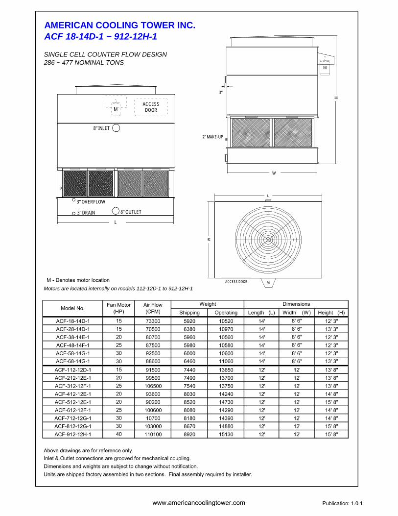
AMERICAN COOLING TOWER INC.ACF 18-14D-1 ~ 912-12H-1
SINGLE CELL COUNTER FLOW DESIGN286 ~ 477 NOMINAL TONS
HWT 90o 95o 90o 95o 97o 95o 95o 100 95o
CWT 80o 80o 80o 85o 82o 85o 85o 85o 85o
AWB 68o 68o 70o 70o 72o 72o 75o 75o 76o
ACF-18-14D-1 286 1027 809 925 1313 773 1211 1044 834 1008ACF-28-14D-1 297 1051 843 954 1325 810 1228 1070 870 1014ACF-38-14E-1 315 1129 891 1018 1440 852 1329 1148 918 1083ACF-48-14F-1 339 1214 959 1095 1546 917 1428 1234 988 1165ACF-58-14G-1 360 1288 1018 1162 1638 974 1513 1309 1049 1236ACF-68-14G-1 373 1312 1058 1193 1647 1017 1530 1337 1091 1267ACF-112-12D-1 304 1122 858 998 1466 813 1341 1137 882 1065ACF-212-12E-1 335 1237 947 1101 1613 898 1476 1254 973 1174ACF-312-12F-1 362 1333 1022 1187 1736 969 1589 1351 1050 1266ACF-412-12E-1 371 1330 1052 1200 1692 1006 1563 1351 1083 1276ACF-512-12E-1 382 1347 1085 1224 1693 1043 1571 1371 1119 1300ACF-612-12F-1 399 1428 1130 1289 1814 1081 1676 1451 1164 1370ACF-712-12G-1 424 1515 1201 1368 1923 1149 1778 1540 1237 1454ACF-812-12G-1 435 1532 1237 1394 1920 1189 1784 1560 1275 1479ACF-912-12H-1 477 1675 1355 1525 2095 1304 1948 1706 1397 1619
HWT 100o 95o 98o 100o 95o 96o 100o 100o 100o
CWT 85o 85o 88o 85o 85o 86o 85o 90o 90o
AWB 76o 78o 78o 78o 80o 80o 80o 80o 82o
ACF-18-14D-1 286 812 858 1124 718 718 832 613 1180 1071ACF-28-14D-1 297 829 892 1148 739 758 848 639 1203 1075ACF-38-14E-1 315 871 944 1235 769 791 892 655 1296 1150ACF-48-14F-1 339 937 1017 1327 828 852 961 706 1393 1236ACF-58-14G-1 360 995 1079 1407 880 906 1020 751 1476 1311ACF-68-14G-1 373 1040 1118 1431 929 952 1063 804 1499 1342ACF-112-12D-1 304 830 912 1231 720 745 854 599 1297 1132ACF-212-12E-1 335 917 1006 1356 796 823 943 662 1429 1248ACF-312-12F-1 362 989 1086 1460 859 889 1017 715 1539 1345ACF-412-12E-1 371 1028 1113 1453 908 934 1053 775 1524 1353ACF-512-12E-1 382 1066 1146 1469 952 975 1089 824 1539 1377ACF-612-12F-1 399 1104 1196 1558 977 1004 1131 833 1635 1452ACF-712-12G-1 424 1174 1271 1654 1039 1069 1203 887 1734 1542ACF-812-12G-1 435 1216 1306 1670 1087 1114 1242 942 1748 1566ACF-912-12H-1 477 1332 1431 1825 1992 1221 1361 1034 1909 1713
Thermal performance of the ACF series models listed above have been certified in accordance to cooling technology institute (CTI) Standand STD-201. Single cell models only.For multiple cell configurations, please contact American Cooling Tower Inc.
Validation C38D-18R00 For design conditions not shown, please contact American Cooling Tower Inc.
Model No. Nominal Tons
Indicated flow rates are in USGPM. Temperatures shown in oF.
Model No. Nominal Tons
Indicated flow rates are in USGPM. Temperatures shown in oF.
www.americancoolingtower.com Publication: 1.0.1
AMERICAN COOLING TOWER INC.ACF 18-14D-1 ~ 912-12H-1
SINGLE CELL COUNTER FLOW DESIGN286 ~ 477 NOMINAL TONS
M - Denotes motor locationMotors are located internally on models 112-12D-1 to 912-12H-1
Shipping Operating Length (L) Width (W) Height (H)ACF-18-14D-1 15 73300 5920 10520 14' 8' 6" 12' 3"ACF-28-14D-1 15 70500 6380 10970 14' 8' 6" 13' 3"ACF-38-14E-1 20 80700 5960 10560 14' 8' 6" 12' 3"ACF-48-14F-1 25 87500 5980 10580 14' 8' 6" 12' 3"ACF-58-14G-1 30 92500 6000 10600 14' 8' 6" 12' 3"ACF-68-14G-1 30 88600 6460 11060 14' 8' 6" 13' 3"ACF-112-12D-1 15 91500 7440 13650 12' 12' 13' 8"ACF-212-12E-1 20 99500 7490 13700 12' 12' 13' 8"ACF-312-12F-1 25 106500 7540 13750 12' 12' 13' 8"ACF-412-12E-1 20 93600 8030 14240 12' 12' 14' 8"ACF-512-12E-1 20 90200 8520 14730 12' 12' 15' 8"ACF-612-12F-1 25 100600 8080 14290 12' 12' 14' 8"ACF-712-12G-1 30 10700 8180 14390 12' 12' 14' 8"ACF-812-12G-1 30 103000 8670 14880 12' 12' 15' 8"ACF-912-12H-1 40 110100 8920 15130 12' 12' 15' 8"
Above drawings are for reference only.Inlet & Outlet connections are grooved for mechanical coupling.Dimensions and weights are subject to change without notification.Units are shipped factory assembled in two sections. Final assembly required by installer.
DimensionsModel No. Fan Motor
(HP)Air Flow (CFM)
Weight
L
ACCESSDOOR
8” INLET
8” OUTLET3” DRAIN
3” OVERFLOW
3”
W
H
2” MAKE-UP
ACCESS DOOR M
L
W

www.americancoolingtower.com Publication: 1.0.1
AMERICAN COOLING TOWER INC.ACF 18-14D-1 ~ 912-12H-1
SINGLE CELL COUNTER FLOW DESIGNRECOMMENDED TOWER SUPPORT LAYOUT
A B C D E F GACF-18-14D-1 5920 10520 (8) 3/4" 14' -0" 8' -6" 5" 72" 14" 100 3/8" 13/16" 1315ACF-28-14D-1 6380 10970 (8) 3/4" 14' -0" 8' -6" 5" 72" 14" 100 3/8" 13/16" 1371ACF-38-14E-1 5960 10560 (8) 3/4" 14' -0" 8' -6" 5" 72" 14" 100 3/8" 13/16" 1320ACF-48-14F-1 5980 10580 (8) 3/4" 14' -0" 8' -6" 5" 72" 14" 100 3/8" 13/16" 1323ACF-58-14G-1 6000 10600 (8) 3/4" 14' -0" 8' -6" 5" 72" 14" 100 3/8" 13/16" 1325ACF-68-14G-1 6460 11060 (8) 3/4" 14' -0" 8' -6" 5" 72" 14" 100 3/8" 13/16" 1383ACF-112-12D-1 7440 13650 (8) 3/4" 12' -0" 12' -0" 5" 59" 16" 142 3/8" 13/16" 1706ACF-212-12E-1 7490 13700 (8) 3/4" 12' -0" 12' -0" 5" 59" 16" 142 3/8" 13/16" 1713ACF-312-12F-1 7540 13750 (8) 3/4" 12' -0" 12' -0" 5" 59" 16" 142 3/8" 13/16" 1719ACF-412-12E-1 8030 14240 (8) 3/4" 12' -0" 12' -0" 5" 59" 16" 142 3/8" 13/16" 1780ACF-512-12E-1 8520 14730 (8) 3/4" 12' -0" 12' -0" 5" 59" 16" 142 3/8" 13/16" 1841ACF-612-12F-1 8080 14290 (8) 3/4" 12' -0" 12' -0" 5" 59" 16" 142 3/8" 13/16" 1786ACF-712-12G-1 8180 14390 (8) 3/4" 12' -0" 12' -0" 5" 59" 16" 142 3/8" 13/16" 1799ACF-812-12G-1 8670 14880 (8) 3/4" 12' -0" 12' -0" 5" 59" 16" 142 3/8" 13/16" 1860ACF-912-12H-1 8920 15130 (8) 3/4" 12' -0" 12' -0" 5" 59" 16" 142 3/8" 13/16" 1891
Support steel selection and anchors by others.All steel supports must have a level installation surface. Applicable building codes may require alternate support designs. For alternate support designs please consult the factory. Weights are subject to change and do not include any options or accessories.
Load Per Anchor (lbs)Model No. Shipping
Weight (lbs)Operating
Weight (lbs)Anchor Bolt Qty
& DiameterDimensions
CL
MOUNTING HOLESEIGHT (8) TOTAL
UNIT OUTLINE
TOWER LOAD
C CD DEA
G
F B
UNIT OUTLINE
MOUNTING HOLESEIGHT (8) TOTAL

www.americancoolingtower.com Publication: 1.0.1
AMERICAN COOLING TOWER INC.ACF 112-14G-1 ~ 812-20K-1
SINGLE CELL COUNTER FLOW DESIGN416 ~ 768 NOMINAL TONS
HWT 90o 95o 90o 95o 97o 95o 95o 100 95o
CWT 80o 80o 80o 85o 82o 85o 85o 85o 85o
AWB 68o 68o 70o 70o 72o 72o 75o 75o 76o
ACF-112-14G-1 416 1534 1174 1366 2000 1113 1830 1555 1207 1457ACF-212-14F-1 434 1556 1230 1404 1982 1176 1830 1582 1267 1493ACF-312-14G-1 476 1676 1351 1523 2104 1298 1953 1706 1393 1618ACF-412-14H-1 507 1811 1436 1636 2298 1374 2125 1841 1479 1739ACF-512-14H-1 522 1835 1482 1670 2300 1425 2137 1869 1528 1772ACF-112-18G-1 563 2016 1594 1819 2568 1524 2371 2050 1642 1935ACF-212-18G-1 581 2049 1650 1862 2576 1586 2391 2087 1702 1978ACF-312-18H-1 619 2214 1753 1999 2814 1677 2600 2251 1806 2125ACF-412-18H-1 638 2247 1812 2043 2820 1742 2618 2288 1869 2170ACF-512-18J-1 666 2378 1886 2148 3017 1804 2790 2418 1942 2284ACF-612-18K-1 726 2552 2064 2323 3192 1985 2968 2598 2128 2465ACF-712-20J-1 700 2506 1983 2262 3187 1897 2944 2548 2043 2405ACF-812-20K-1 768 2701 2180 2457 3386 2096 3145 2751 2248 2609
HWT 100o 95o 98o 100o 95o 96o 100o 100o 100o
CWT 85o 85o 88o 85o 85o 86o 85o 90o 90o
AWB 76o 78o 78o 78o 80o 80o 80o 80o 82o
ACF-112-14G-1 416 1137 1249 1682 987 1022 1170 822 1772 1549ACF-212-14F-1 434 1202 1303 1701 1062 1093 1232 906 1785 1584ACF-312-14G-1 476 1327 1427 1828 1186 1215 1356 1026 1914 1714ACF-412-14H-1 507 1404 1520 1977 1242 1278 1438 1061 2074 1843ACF-512-14H-1 522 1457 1565 2001 1303 1335 1489 1128 1094 1877ACF-112-18G-1 563 1558 1689 2204 1377 1417 1596 1174 2313 2052ACF-212-18G-1 581 1621 1744 2236 1448 1484 1657 1252 2342 2096ACF-312-18H-1 619 1714 1857 2419 1516 1559 1756 1293 2537 2254ACF-412-18H-1 638 1781 1915 2451 1592 1631 1820 1378 2566 2298ACF-512-18J-1 666 1844 1997 2597 1632 1679 1889 1394 2723 2421ACF-612-18K-1 726 2029 2179 2781 1816 1860 2073 1574 2909 2610ACF-712-20J-1 700 1938 2101 2738 1714 1764 1986 1462 2873 2551ACF-812-20K-1 768 2143 2303 2945 1916 1963 2190 1660 3083 2763
Thermal performance of the ACF series models listed above have been certified in accordance to cooling technology institute (CTI) Standand STD-201. Single cell models only.For multiple cell configurations, please contact American Cooling Tower Inc.
Validation C38D-18R00 For design conditions not shown, please contact American Cooling Tower Inc.
Model No. Nominal Tons
Indicated flow rates are in USGPM. Temperatures shown in oF.
Model No. Nominal Tons
Indicated flow rates are in USGPM. Temperatures shown in oF.

www.americancoolingtower.com Publication: 1.0.1
AMERICAN COOLING TOWER INC.ACF 112-14G-1 ~ 812-20K-1
SINGLE CELL COUNTER FLOW DESIGN416 ~ 768 NOMINAL TONS
M - Denotes motor location
Shipping Operating Length (L) Width (W) Height (H)ACF-112-14G-1 30 122200 8270 15600 14' 12' 14' 2"ACF-212-14F-1 25 109000 8860 16190 14' 12' 15' 2"ACF-312-14G-1 30 112000 9450 16780 14' 12' 16' 2"ACF-412-14H-1 40 127000 9190 16520 14' 12' 15' 2"ACF-512-14H-1 40 122500 9710 17040 14' 12' 16' 2"ACF-112-18G-1 30 142000 11260 20530 18' 12' 15' 8"ACF-212-18G-1 30 137000 12000 21270 18' 12' 16' 8"ACF-312-18H-1 40 156000 11520 20790 18' 12' 15' 8"ACF-412-18H-1 40 150200 12260 21530 18' 12' 16' 8"ACF-512-18J-1 50 167000 11580 20850 18' 12' 15' 8"ACF-612-18K-1 60 167300 12430 21700 18' 12' 15' 8"ACF-712-20J-1 50 175000 12230 22630 20' 12' 15' 8"ACF-812-20K-1 60 174300 13240 23640 20' 12' 16' 8"
Above drawings are for reference only.Inlet & Outlet connections are grooved for mechanical coupling.Dimensions and weights are subject to change without notification.Units are shipped factory assembled in two sections. Final assembly required by installer.
Model No. Fan Motor (HP)
Air Flow (CFM)
Weight Dimensions
L
ACCESSDOOR
10” INLET
10” OUTLET3” DRAIN
3” OVERFLOW
W
3”
2” MAKE-UP
H
ACCESS DOOR
M
L
W

www.americancoolingtower.com Publication: 1.0.1
AMERICAN COOLING TOWER INC.ACF 112-14G-1 ~ 812-20K-1
SINGLE CELL COUNTER FLOW DESIGNRECOMMENDED TOWER SUPPORT LAYOUT
A B C D E F GACF-112-14G-1 8270 15600 (12) 3/4" 14' -0" 12' -0" 6" 34 1/2" 18" 142 3/8" 13/16" 1300ACF-212-14F-1 8860 16190 (12) 3/4" 14' -0" 12' -0" 6" 34 1/2" 18" 142 3/8" 13/16" 1349ACF-312-14G-1 9450 16780 (12) 3/4" 14' -0" 12' -0" 6" 34 1/2" 18" 142 3/8" 13/16" 1398ACF-412-14H-1 9190 16520 (12) 3/4" 14' -0" 12' -0" 6" 34 1/2" 18" 142 3/8" 13/16" 1377ACF-512-14H-1 9710 17040 (12) 3/4" 14' -0" 12' -0" 6" 34 1/2" 18" 142 3/8" 13/16" 1420ACF-112-18G-1 11260 20530 (12) 3/4" 18' -0" 12' -0" 8" 45" 20" 142 3/8" 13/16" 1711ACF-212-18G-1 12000 21270 (12) 3/4" 18' -0" 12' -0" 8" 45" 20" 142 3/8" 13/16" 1773ACF-312-18H-1 11520 20790 (12) 3/4" 18' -0" 12' -0" 8" 45" 20" 142 3/8" 13/16" 1733ACF-412-18H-1 12260 21530 (12) 3/4" 18' -0" 12' -0" 8" 45" 20" 142 3/8" 13/16" 1794ACF-512-18J-1 11580 20850 (12) 3/4" 18' -0" 12' -0" 8" 45" 20" 142 3/8" 13/16" 1738ACF-612-18K-1 12430 21700 (12) 3/4" 18' -0" 12' -0" 8" 45" 20" 142 3/8" 13/16" 1808ACF-712-20J-1 12230 22630 (12) 3/4" 20' -0" 12' -0" 10" 49" 24" 142 3/8" 13/16" 1886ACF-812-20K-1 13240 23640 (12) 3/4" 20' -0" 12' -0" 10" 49" 24" 142 3/8" 13/16" 1970
Support steel selection and anchors by others.All steel supports must have a level installation surface. Applicable building codes may require alternate support designs. For alternate support designs please consult the factory. Weights are subject to change and do not include any options or accessories.
Model No. Load Per Anchor (lbs)
Dimensions Anchor Bolt Qty & Diameter
Operating Weight (lbs)
Shipping Weight (lbs)
CL
MOUNTING HOLESTWELVE (12) TOTAL
UNIT OUTLINE
TOWER LOAD
C CD D D DA
G
F B
UNIT OUTLINE
MOUNTING HOLESTWELVE (12) TOTAL
E
www.americancoolingtower.com Publication: 1.0.1
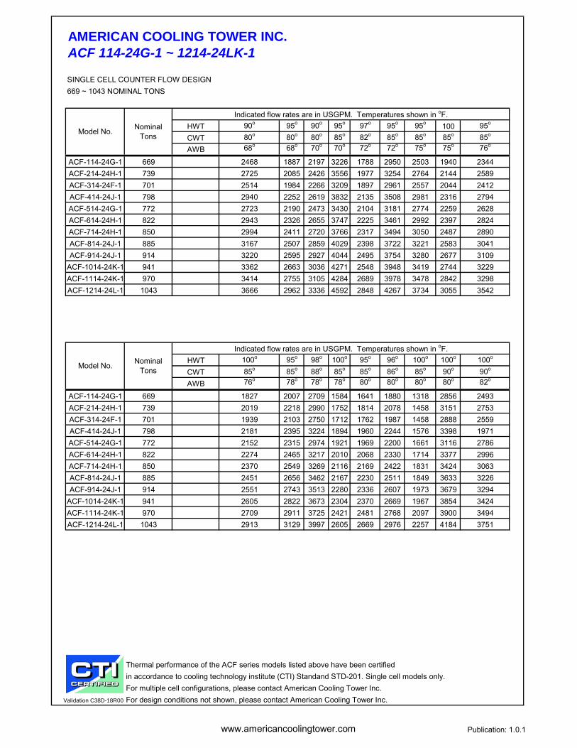
AMERICAN COOLING TOWER INC.ACF 114-24G-1 ~ 1214-24LK-1
SINGLE CELL COUNTER FLOW DESIGN669 ~ 1043 NOMINAL TONS
HWT 90o 95o 90o 95o 97o 95o 95o 100 95o
CWT 80o 80o 80o 85o 82o 85o 85o 85o 85o
AWB 68o 68o 70o 70o 72o 72o 75o 75o 76o
ACF-114-24G-1 669 2468 1887 2197 3226 1788 2950 2503 1940 2344ACF-214-24H-1 739 2725 2085 2426 3556 1977 3254 2764 2144 2589ACF-314-24F-1 701 2514 1984 2266 3209 1897 2961 2557 2044 2412ACF-414-24J-1 798 2940 2252 2619 3832 2135 3508 2981 2316 2794ACF-514-24G-1 772 2723 2190 2473 3430 2104 3181 2774 2259 2628ACF-614-24H-1 822 2943 2326 2655 3747 2225 3461 2992 2397 2824ACF-714-24H-1 850 2994 2411 2720 3766 2317 3494 3050 2487 2890ACF-814-24J-1 885 3167 2507 2859 4029 2398 3722 3221 2583 3041ACF-914-24J-1 914 3220 2595 2927 4044 2495 3754 3280 2677 3109
ACF-1014-24K-1 941 3362 2663 3036 4271 2548 3948 3419 2744 3229ACF-1114-24K-1 970 3414 2755 3105 4284 2689 3978 3478 2842 3298ACF-1214-24L-1 1043 3666 2962 3336 4592 2848 4267 3734 3055 3542
HWT 100o 95o 98o 100o 95o 96o 100o 100o 100o
CWT 85o 85o 88o 85o 85o 86o 85o 90o 90o
AWB 76o 78o 78o 78o 80o 80o 80o 80o 82o
ACF-114-24G-1 669 1827 2007 2709 1584 1641 1880 1318 2856 2493ACF-214-24H-1 739 2019 2218 2990 1752 1814 2078 1458 3151 2753ACF-314-24F-1 701 1939 2103 2750 1712 1762 1987 1458 2888 2559ACF-414-24J-1 798 2181 2395 3224 1894 1960 2244 1576 3398 1971ACF-514-24G-1 772 2152 2315 2974 1921 1969 2200 1661 3116 2786ACF-614-24H-1 822 2274 2465 3217 2010 2068 2330 1714 3377 2996ACF-714-24H-1 850 2370 2549 3269 2116 2169 2422 1831 3424 3063ACF-814-24J-1 885 2451 2656 3462 2167 2230 2511 1849 3633 3226ACF-914-24J-1 914 2551 2743 3513 2280 2336 2607 1973 3679 3294
ACF-1014-24K-1 941 2605 2822 3673 2304 2370 2669 1967 3854 3424ACF-1114-24K-1 970 2709 2911 3725 2421 2481 2768 2097 3900 3494ACF-1214-24L-1 1043 2913 3129 3997 2605 2669 2976 2257 4184 3751
Thermal performance of the ACF series models listed above have been certified in accordance to cooling technology institute (CTI) Standand STD-201. Single cell models only.For multiple cell configurations, please contact American Cooling Tower Inc.
Validation C38D-18R00 For design conditions not shown, please contact American Cooling Tower Inc.
Model No. Nominal Tons
Indicated flow rates are in USGPM. Temperatures shown in oF.
Model No. Nominal Tons
Indicated flow rates are in USGPM. Temperatures shown in oF.

www.americancoolingtower.com Publication: 1.0.1
AMERICAN COOLING TOWER INC.ACF 114-24G-1 ~ 1214-24LK-1
SINGLE CELL COUNTER FLOW DESIGN669 ~ 1043 NOMINAL TONS
M - Denotes motor location
Shipping Operating Length (L) Width (W) Height (H)ACF-114-24G-1 30 194100 16510 32360 24' 14' 17' 6"ACF-214-24H-1 40 210000 16660 32510 24' 14' 17' 6"ACF-314-24F-1 25 182000 18570 34420 24' 14' 19' 6"ACF-414-24J-1 50 225000 17010 32860 24' 14' 17' 6"ACF-514-24G-1 30 183000 18590 34440 24' 14' 19' 6"ACF-614-24H-1 40 204400 17700 33550 24' 14' 18' 6"ACF-714-24H-1 40 200800 18740 34590 24' 14' 19' 6"ACF-814-24J-1 50 218000 18050 33900 24' 14' 18' 6"ACF-914-24J-1 50 211500 19090 34940 24' 14' 19' 6"
ACF-1014-24K-1 60 230700 18220 34070 24' 14' 18' 6"ACF-1114-24K-1 60 224000 19260 35110 24' 14' 19' 6"ACF-1214-24L-1 75 235600 19500 35350 24' 14' 19' 6"
Above drawings are for reference only.Inlet & Outlet connections are grooved for mechanical coupling.Dimensions and weights are subject to change without notification.Units are shipped factory assembled in two sections. Final assembly required by installer.
Model No. Fan Motor (HP)
Air Flow (CFM)
Weight Dimensions
L
14” INLET
14” OUTLET4” DRAIN
4” OVERFLOW
ACCESSDOOR
W
3”
3” MAKE-UP
H
ACCESS DOOR
M
L
W
www.americancoolingtower.com Publication: 1.0.1
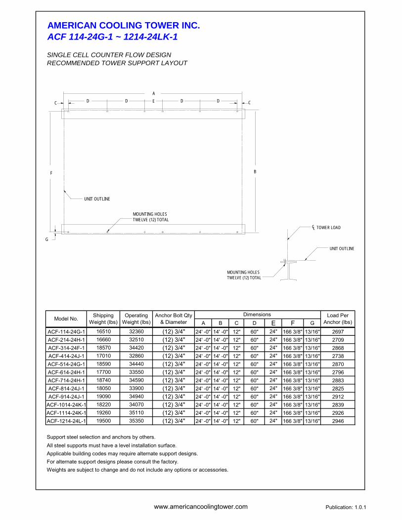
AMERICAN COOLING TOWER INC.ACF 114-24G-1 ~ 1214-24LK-1
SINGLE CELL COUNTER FLOW DESIGNRECOMMENDED TOWER SUPPORT LAYOUT
A B C D E F GACF-114-24G-1 16510 32360 (12) 3/4" 24' -0" 14' -0" 12" 60" 24" 166 3/8" 13/16" 2697ACF-214-24H-1 16660 32510 (12) 3/4" 24' -0" 14' -0" 12" 60" 24" 166 3/8" 13/16" 2709ACF-314-24F-1 18570 34420 (12) 3/4" 24' -0" 14' -0" 12" 60" 24" 166 3/8" 13/16" 2868ACF-414-24J-1 17010 32860 (12) 3/4" 24' -0" 14' -0" 12" 60" 24" 166 3/8" 13/16" 2738ACF-514-24G-1 18590 34440 (12) 3/4" 24' -0" 14' -0" 12" 60" 24" 166 3/8" 13/16" 2870ACF-614-24H-1 17700 33550 (12) 3/4" 24' -0" 14' -0" 12" 60" 24" 166 3/8" 13/16" 2796ACF-714-24H-1 18740 34590 (12) 3/4" 24' -0" 14' -0" 12" 60" 24" 166 3/8" 13/16" 2883ACF-814-24J-1 18050 33900 (12) 3/4" 24' -0" 14' -0" 12" 60" 24" 166 3/8" 13/16" 2825ACF-914-24J-1 19090 34940 (12) 3/4" 24' -0" 14' -0" 12" 60" 24" 166 3/8" 13/16" 2912
ACF-1014-24K-1 18220 34070 (12) 3/4" 24' -0" 14' -0" 12" 60" 24" 166 3/8" 13/16" 2839ACF-1114-24K-1 19260 35110 (12) 3/4" 24' -0" 14' -0" 12" 60" 24" 166 3/8" 13/16" 2926ACF-1214-24L-1 19500 35350 (12) 3/4" 24' -0" 14' -0" 12" 60" 24" 166 3/8" 13/16" 2946
Support steel selection and anchors by others.All steel supports must have a level installation surface. Applicable building codes may require alternate support designs. For alternate support designs please consult the factory. Weights are subject to change and do not include any options or accessories.
Dimensions Load Per Anchor (lbs)Model No. Shipping
Weight (lbs)Operating
Weight (lbs)Anchor Bolt Qty
& Diameter
CL
MOUNTING HOLESTWELVE (12) TOTAL
UNIT OUTLINE
TOWER LOAD
C CD D D DA
G
F B
UNIT OUTLINE
MOUNTING HOLESTWELVE (12) TOTAL
E
www.americancoolingtower.com Publication:1.0.1
AMERICAN COOLING TOWER INC.SPECIFICATIONS
GENERAL
1.0 SELECTION 2.1a (OPTION) STAINLESS STEEL COLD WATER BASIN
1.1 PERFORMANCE
MATERIALS OF CONSTRUCTION2.0 STRUCTURE 2.2 INTERNAL SUPPORT MEMBERS
2.1 COLD WATER BASIN
2.2a (OPTION) STAINLESS STEEL INTERNAL SUPPORTS
2.3 CASING PANELS
*Options are indicated in italics or stated as (OPTION).
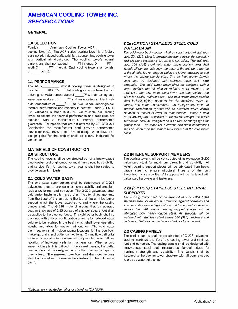
Furnish _____ American Cooling Tower ACF- __________cooling tower(s). The ACF series cooling tower is a factoryassembled, induced draft, axial fan, counter flow cooling towerwith vertical air discharge. The cooling tower’s overalldimensions shall not exceed _____FT in length X _____FT inwidth X _____ FT in height. Each cooling tower shall consistof _____ cell(s).
The ACF-__________ model cooling tower is designed toprovide _____USGPM of total cooling capacity based on anentering hot water temperature of _____oF with an exiting coldwater temperature of _____oF and an entering ambient wet-bulb temperature of _____oF. The ACF Series unit single cellthermal performance and capacity is certified under CTI STD201 validation number 10-38-01. On multiple cell coolingtower selections the thermal performance and capacities aresupplied with a manufacturer’s thermal performanceguarantee. For models that are not covered by CTI STD 201Certification the manufacturer shall provide performancecurves for 90%, 100%, and 110% of design water flow. Thedesign point for the project shall be clearly indicated forverification.
The cooling tower shall be constructed out of a heavy-gaugesteel design and engineered for maximum strength, durability,and service life. All cooling tower seams shall be sealed toprovide watertight joints.
The cold water basin section shall be constructed of stainlesssteel 304 (316) steel to provide superior service life, durabilityand excellent resistance to rust and corrosion. The stainlesssteel 304 (316) steel cold water basin section area shallinclude all components from the base of the unit up to the topof the air inlet louver support which the louver attaches to and where the casing panels start. The air inlet louver framesshall also be designed with stainless steel 304 (316)materials. The cold water basin shall be designed with atiered configuration allowing for reduced water volume to beretained in the basin which shall lower operating weight, andallow for easier maintenance. The cold water basin sectionshall include piping locations for the overflow, make-up,adrain, and outlet connections. On multiple cell units aninternal equalization system will be provided which allowsisolation of individual cells for maintenance. When a coldwater holding tank is utilized in the overall design, the outletconnection shall be designed as a bottom discharge type forgravity feed. The make-up, overflow, and drain connectionsshall be located on the remote tank instead of the cold waterbasin.
The casing panels shall be constructed of G-235 galvanizedsteel to maximize the life of the cooling tower and minimizerust and corrosion. The casing panels shall be designed withheavy-gauge steel that incorporates flanged edges formaximum strength and durability. The panels shall befastened to the cooling tower structure with all seams sealedto provide watertight joints.
The cooling tower shall be constructed of series 304 (316)stainless steel for maximum protection against corrosion andto ensure structural integrity of the unit throughout its superiorservice life. All weight bearing support pieces will befabricated from heavy gauge steel. All supports will befastened with stainless steel series 304 (316) hardware andfasteners. Self tapping fasteners shall not be accepted.
The cold water basin section shall be constructed of G-235galvanized steel to provide maximum durability and excellentresistance to rust and corrosion. The G-235 galvanized steelcold water basin section area shall include all componentsfrom the base of the unit up to the top of the air inlet louversupport which the louver attaches to and where the casingpanels start. The G-235 material means that an averagecoating thickness of 2.35 ounces of zinc per square foot shallbe applied to the steel surfaces. The cold water basin shall be designed with a tiered configuration allowing for reduced watervolume to be retained in the basin which shall lower operatingweight, and allow for easier maintenance. The cold waterbasin section shall include piping locations for the overflow,make-up, drain, and outlet connections. On multiple cell unitsan internal equalization system will be provided which allowsisolation of individual cells for maintenance. When a coldwater holding tank is utilized in the overall design, the outletconnection shall be designed as a bottom discharge type forgravity feed. The make-up, overflow, and drain connectionsshall be located on the remote tank instead of the cold waterbasin.
The cooling tower shall be constructed of heavy-gauge G-235galvanized steel for maximum strength and durability. Allweight bearing support pieces will be fabricated from heavygauge steel to ensure structural integrity of the unitthroughout its service life. All supports will be fastened withgalvanized hardware and fasteners.
www.americancoolingtower.com Publication:1.0.1
AMERICAN COOLING TOWER INC.SPECIFICATIONS
2.3a (OPTION) STAINLESS STEEL CASING 3.4 FANPANELS
3.0 MECHANICAL COMPONENTS3.1 FAN MOTOR
3.5 MECHANICAL WARRANTY
4.0 WATER DISTRIBUTION4.1 WATER DISTRIBUTION SYSTEM
3.2 FAN DRIVE
3.3 BEARINGS
*Options are indicated in italics or stated as (OPTION).
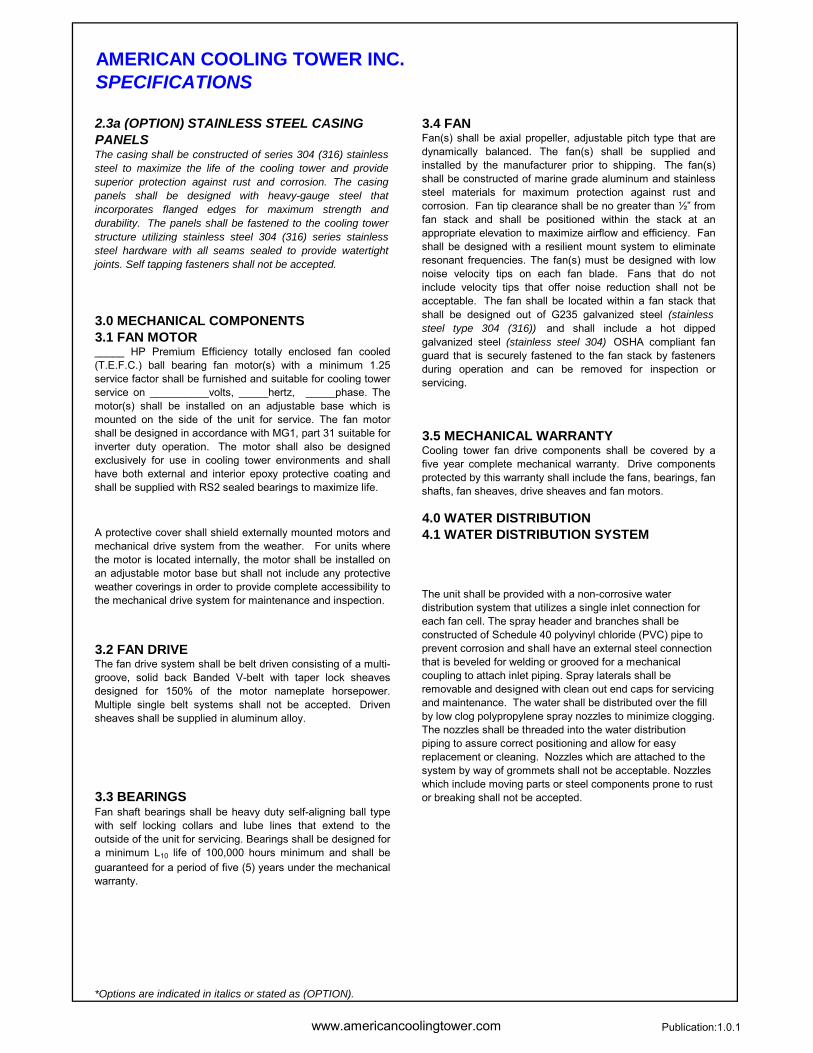
The casing shall be constructed of series 304 (316) stainlesssteel to maximize the life of the cooling tower and providesuperior protection against rust and corrosion. The casingpanels shall be designed with heavy-gauge steel thatincorporates flanged edges for maximum strength anddurability. The panels shall be fastened to the cooling towerstructure utilizing stainless steel 304 (316) series stainlesssteel hardware with all seams sealed to provide watertightjoints. Self tapping fasteners shall not be accepted.
_____ HP Premium Efficiency totally enclosed fan cooled(T.E.F.C.) ball bearing fan motor(s) with a minimum 1.25service factor shall be furnished and suitable for cooling towerservice on __________volts, _____hertz, _____phase. Themotor(s) shall be installed on an adjustable base which ismounted on the side of the unit for service. The fan motorshall be designed in accordance with MG1, part 31 suitable forinverter duty operation. The motor shall also be designedexclusively for use in cooling tower environments and shallhave both external and interior epoxy protective coating andshall be supplied with RS2 sealed bearings to maximize life.
A protective cover shall shield externally mounted motors andmechanical drive system from the weather. For units wherethe motor is located internally, the motor shall be installed onan adjustable motor base but shall not include any protectiveweather coverings in order to provide complete accessibility tothe mechanical drive system for maintenance and inspection.
Fan(s) shall be axial propeller, adjustable pitch type that aredynamically balanced. The fan(s) shall be supplied andinstalled by the manufacturer prior to shipping. The fan(s)shall be constructed of marine grade aluminum and stainlesssteel materials for maximum protection against rust andcorrosion. Fan tip clearance shall be no greater than ½” fromfan stack and shall be positioned within the stack at anappropriate elevation to maximize airflow and efficiency. Fanshall be designed with a resilient mount system to eliminateresonant frequencies. The fan(s) must be designed with lownoise velocity tips on each fan blade. Fans that do notinclude velocity tips that offer noise reduction shall not beacceptable. The fan shall be located within a fan stack thatshall be designed out of G235 galvanized steel (stainless steel type 304 (316)) and shall include a hot dippedgalvanized steel (stainless steel 304) OSHA compliant fanguard that is securely fastened to the fan stack by fastenersduring operation and can be removed for inspection orservicing.
Cooling tower fan drive components shall be covered by afive year complete mechanical warranty. Drive componentsprotected by this warranty shall include the fans, bearings, fanshafts, fan sheaves, drive sheaves and fan motors.
The unit shall be provided with a non-corrosive water distribution system that utilizes a single inlet connection for each fan cell. The spray header and branches shall be constructed of Schedule 40 polyvinyl chloride (PVC) pipe to prevent corrosion and shall have an external steel connection that is beveled for welding or grooved for a mechanical coupling to attach inlet piping. Spray laterals shall be removable and designed with clean out end caps for servicing and maintenance. The water shall be distributed over the fill by low clog polypropylene spray nozzles to minimize clogging. The nozzles shall be threaded into the water distribution piping to assure correct positioning and allow for easy replacement or cleaning. Nozzles which are attached to the system by way of grommets shall not be acceptable. Nozzles which include moving parts or steel components prone to rust or breaking shall not be accepted.
Fan shaft bearings shall be heavy duty self-aligning ball typewith self locking collars and lube lines that extend to theoutside of the unit for servicing. Bearings shall be designed fora minimum L10 life of 100,000 hours minimum and shall beguaranteed for a period of five (5) years under the mechanicalwarranty.
The fan drive system shall be belt driven consisting of a multi-groove, solid back Banded V-belt with taper lock sheavesdesigned for 150% of the motor nameplate horsepower.Multiple single belt systems shall not be accepted. Drivensheaves shall be supplied in aluminum alloy.
www.americancoolingtower.com Publication:1.0.1
AMERICAN COOLING TOWER INC.SPECIFICATIONS
5.0 FILL MEDIA AND DRIFT ELIMINATORS 8.0 SOUND5.1 FILL MEDIA 8.1 SOUND LEVEL
5.2 DRIFT ELIMINATORS9.0 ACCESSORIES9.1 VIBRATION SWITCH
6.0 AIR INLET LOUVERS6.1 INLET LOUVERS
9.2 BASIN HEATER
9.3 ELECTRONIC WATER LEVEL CONTROL
7.0 QUALITY ASSURANCE7.1 QUALITY CONTROL
*Options are indicated in italics or stated as (OPTION).
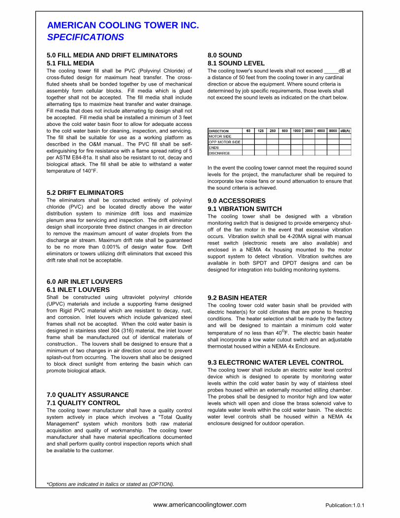
The cooling tower's sound levels shall not exceed _____dB at a distance of 50 feet from the cooling tower in any cardinal direction or above the equipment. Where sound criteria is determined by job specific requirements, those levels shall not exceed the sound levels as indicated on the chart below.
In the event the cooling tower cannot meet the required soundlevels for the project, the manufacturer shall be required toincorporate low noise fans or sound attenuation to ensure thatthe sound criteria is achieved.
The cooling tower shall be designed with a vibrationmonitoring switch that is designed to provide emergency shut-off of the fan motor in the event that excessive vibrationoccurs. Vibration switch shall be 4-20MA signal with manualreset switch (electronic resets are also available) andenclosed in a NEMA 4x housing mounted to the motorsupport system to detect vibration. Vibration switches areavailable in both SPDT and DPDT designs and can bedesigned for integration into building monitoring systems.
The cooling tower cold water basin shall be provided withelectric heater(s) for cold climates that are prone to freezingconditions. The heater selection shall be made by the factoryand will be designed to maintain a minimum cold watertemperature of no less than 40OF. The electric basin heatershall incorporate a low water cutout switch and an adjustablethermostat housed within a NEMA 4x Enclosure.
The cooling tower shall include an electric water level controldevice which is designed to operate by monitoring waterlevels within the cold water basin by way of stainless steelprobes housed within an externally mounted stilling chamber.The probes shall be designed to monitor high and low waterlevels which will open and close the brass solenoid valve toregulate water levels within the cold water basin. The electricwater level controls shall be housed within a NEMA 4xenclosure designed for outdoor operation.
The eliminators shall be constructed entirely of polyvinylchloride (PVC) and be located directly above the waterdistribution system to minimize drift loss and maximizeplenum area for servicing and inspection. The drift eliminatordesign shall incorporate three distinct changes in air directionto remove the maximum amount of water droplets from thedischarge air stream. Maximum drift rate shall be guaranteedto be no more than 0.001% of design water flow. Drifteliminators or towers utilizing drift eliminators that exceed thisdrift rate shall not be acceptable.
Shall be constructed using ultraviolet polyvinyl chloride(UPVC) materials and include a supporting frame designedfrom Rigid PVC material which are resistant to decay, rust,and corrosion. Inlet louvers which include galvanized steelframes shall not be accepted. When the cold water basin isdesigned in stainless steel 304 (316) material, the inlet louverframe shall be manufactured out of identical materials ofconstruction.. The louvers shall be designed to ensure that aminimum of two changes in air direction occur and to preventsplash-out from occurring. The louvers shall also be designedto block direct sunlight from entering the basin which canpromote biological attack.
The cooling tower fill shall be PVC (Polyvinyl Chloride) ofcross-fluted design for maximum heat transfer. The cross-fluted sheets shall be bonded together by use of mechanicalassembly form cellular blocks. Fill media which is gluedtogether shall not be accepted. The fill media shall includealternating tips to maximize heat transfer and water drainage.Fill media that does not include alternating tip design shall notbe accepted. Fill media shall be installed a minimum of 3 feetabove the cold water basin floor to allow for adequate accessto the cold water basin for cleaning, inspection, and servicing.The fill shall be suitable for use as a working platform asdescribed in the O&M manual.. The PVC fill shall be self-extinguishing for fire resistance with a flame spread rating of 5per ASTM E84-81a. It shall also be resistant to rot, decay andbiological attack. The fill shall be able to withstand a watertemperature of 140°F.
The cooling tower manufacturer shall have a quality controlsystem actively in place which involves a "Total QualityManagement" system which monitors both raw materialacquisition and quality of workmanship. The cooling towermanufacturer shall have material specifications documentedand shall perform quality control inspection reports which shallbe available to the customer.
www.americancoolingtower.com Publication:1.0.1
AMERICAN COOLING TOWER INC.SPECIFICATIONS
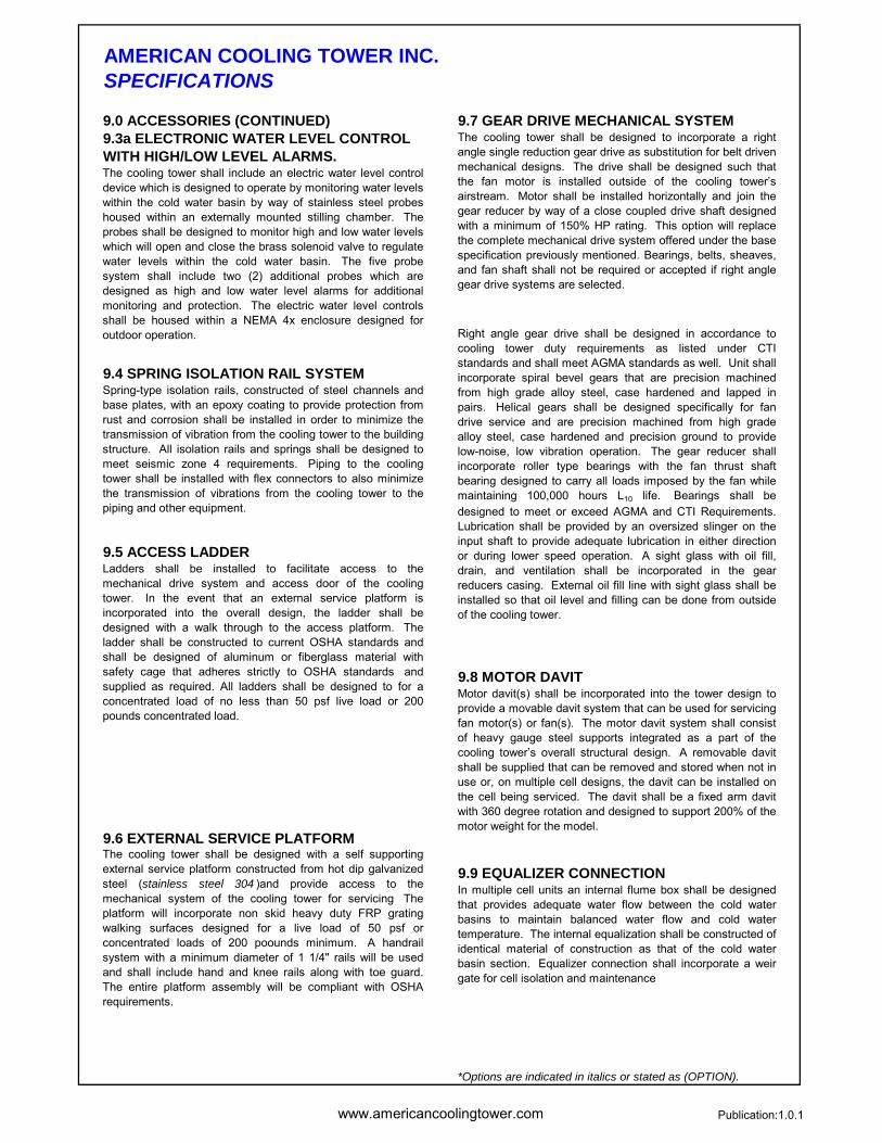
9.0 ACCESSORIES (CONTINUED) 9.7 GEAR DRIVE MECHANICAL SYSTEM9.3a ELECTRONIC WATER LEVEL CONTROL WITH HIGH/LOW LEVEL ALARMS.
9.4 SPRING ISOLATION RAIL SYSTEM
9.5 ACCESS LADDER
9.8 MOTOR DAVIT
9.6 EXTERNAL SERVICE PLATFORM
9.9 EQUALIZER CONNECTION
*Options are indicated in italics or stated as (OPTION).
Spring-type isolation rails, constructed of steel channels andbase plates, with an epoxy coating to provide protection fromrust and corrosion shall be installed in order to minimize thetransmission of vibration from the cooling tower to the buildingstructure. All isolation rails and springs shall be designed tomeet seismic zone 4 requirements. Piping to the coolingtower shall be installed with flex connectors to also minimizethe transmission of vibrations from the cooling tower to thepiping and other equipment.
The cooling tower shall include an electric water level controldevice which is designed to operate by monitoring water levelswithin the cold water basin by way of stainless steel probeshoused within an externally mounted stilling chamber. Theprobes shall be designed to monitor high and low water levelswhich will open and close the brass solenoid valve to regulatewater levels within the cold water basin. The five probesystem shall include two (2) additional probes which aredesigned as high and low water level alarms for additionalmonitoring and protection. The electric water level controlsshall be housed within a NEMA 4x enclosure designed foroutdoor operation.
The cooling tower shall be designed with a self supportingexternal service platform constructed from hot dip galvanizedsteel (stainless steel 304 )and provide access to themechanical system of the cooling tower for servicing Theplatform will incorporate non skid heavy duty FRP gratingwalking surfaces designed for a live load of 50 psf orconcentrated loads of 200 poounds minimum. A handrailsystem with a minimum diameter of 1 1/4" rails will be usedand shall include hand and knee rails along with toe guard.The entire platform assembly will be compliant with OSHArequirements.
The cooling tower shall be designed to incorporate a rightangle single reduction gear drive as substitution for belt drivenmechanical designs. The drive shall be designed such thatthe fan motor is installed outside of the cooling tower’sairstream. Motor shall be installed horizontally and join thegear reducer by way of a close coupled drive shaft designedwith a minimum of 150% HP rating. This option will replacethe complete mechanical drive system offered under the basespecification previously mentioned. Bearings, belts, sheaves,and fan shaft shall not be required or accepted if right anglegear drive systems are selected.
Right angle gear drive shall be designed in accordance tocooling tower duty requirements as listed under CTIstandards and shall meet AGMA standards as well. Unit shallincorporate spiral bevel gears that are precision machinedfrom high grade alloy steel, case hardened and lapped inpairs. Helical gears shall be designed specifically for fandrive service and are precision machined from high gradealloy steel, case hardened and precision ground to providelow-noise, low vibration operation. The gear reducer shallincorporate roller type bearings with the fan thrust shaftbearing designed to carry all loads imposed by the fan whilemaintaining 100,000 hours L10 life. Bearings shall bedesigned to meet or exceed AGMA and CTI Requirements.Lubrication shall be provided by an oversized slinger on theinput shaft to provide adequate lubrication in either directionor during lower speed operation. A sight glass with oil fill,drain, and ventilation shall be incorporated in the gearreducers casing. External oil fill line with sight glass shall beinstalled so that oil level and filling can be done from outsideof the cooling tower.
Ladders shall be installed to facilitate access to themechanical drive system and access door of the coolingtower. In the event that an external service platform isincorporated into the overall design, the ladder shall bedesigned with a walk through to the access platform. Theladder shall be constructed to current OSHA standards andshall be designed of aluminum or fiberglass material withsafety cage that adheres strictly to OSHA standards andsupplied as required. All ladders shall be designed to for aconcentrated load of no less than 50 psf live load or 200pounds concentrated load.
Motor davit(s) shall be incorporated into the tower design toprovide a movable davit system that can be used for servicingfan motor(s) or fan(s). The motor davit system shall consistof heavy gauge steel supports integrated as a part of thecooling tower’s overall structural design. A removable davitshall be supplied that can be removed and stored when not inuse or, on multiple cell designs, the davit can be installed onthe cell being serviced. The davit shall be a fixed arm davitwith 360 degree rotation and designed to support 200% of themotor weight for the model.
In multiple cell units an internal flume box shall be designedthat provides adequate water flow between the cold waterbasins to maintain balanced water flow and cold watertemperature. The internal equalization shall be constructed ofidentical material of construction as that of the cold waterbasin section. Equalizer connection shall incorporate a weirgate for cell isolation and maintenance

www.americancoolingtower.com Publication 1.0.1
AMERICAN COOLING TOWER INC.THERMAL GUARANTEE
AMERICAN COOLING TOWER ACF SERIES COOLING TOWER THERMAL GUARANTEE
Single cell cooling tower models listed at http://www.cti.org/certification.shtml have had their published capacities certified under CTI Standard 201 Test Code and are listed under validation number C38D-18R00
The ACF series packaged cooling tower design manufactured by AMERICAN COOLING TOWER INC., is provided with a THERMAL GUARANTEE stating that based on design conditions presented in bid documents or requirements provided by the
client, tower performance shall meet or exceed a minimum of 95% capacity as is acceptable under CTI Standards & Testing and verified by a Thermal Acceptance Test performed under CTI ATC-105 testing standards certifying that the unit’s thermal
performance has been tested and meets CTI standards for thermal capacity ratings.
Upon the owner’s request an ATC-105 thermal acceptance test can be provided at the owner’s expense if they suspect that the cooling tower is not meeting thermal performance as required by the technical specifications supplied. A thermal acceptance test
shall be provided by a third party testing agency to conduct the ATC-105 thermal acceptance per CTI requirements. Upon completion of the thermal test a report shall be provided to the customer confirming the results. This report will be furnished to both American Cooling Tower and the owner and is considered a legal document and will be recognized as such by all parties
involved.
In the event that the suspected unit(s) do not pass the CTI ATC-105 thermal acceptance test, American Cooling Tower, will be held responsible for making any and all changes to the existing cooling tower(s) or replacing the existing cooling tower(s) to bring the
unit into an acceptable performance range. If the unit(s) fail the ATC-105 thermal acceptance test American Cooling Tower will pay for all upgrades and the testing fees associated to certifying the cooling tower meets design requirements of the project.
Thermal Guarantees will be void should any design conditions be altered without the acknowledgement of American Cooling Tower. Any obstructions that limit air flow or cause air recirculation may also void thermal guarantees. American Cooling Tower provides a thermal guarantee under the assumption that the customer will maintain preventative maintenance as instructed by
AMERICAN COOLING TOWER and uses only Factory Authorized Parts supplied by American Cooling Tower. Any parts, accessories, or optional components not supplied by American Cooling Tower, which may affect cooling performance can void thermal guarantee. The owner should consult with the factory prior to the installation of any components, platforms, ladders, or
other accessories that may affect cooling tower performance.
STD-201 VALIDATION NUMBER C38D-18R00
www.americancoolingtower.com Publication 1.0.1
AMERICAN COOLING TOWER INC.ACF SERIES WARRANTY
American Cooling Tower also offers an extended warranty for the ACF Series Cooling Tower which provides total product coverage for a period of five (5) years.
For more information please contact your representative or you can call 1-800-371-5959.
One Year Mechanical Warranty - One Year Total Product
AMERICAN COOLING TOWER warrants the mechanical equipment of their ACF™ series packaged system which includes the bearings, fan(s), fan motor(s), pulley(s), shaft(s), and mechanical support(s) for a period of one (1) year from the date of shipment by AMERICAN COOLING TOWER. Warranty coverage ensures that the mechanical components of the ACF™ series cooling tower will be free of defects in materials and workmanship. Any component not mentioned previously will be guaranteed to be free of defects associated with materials or workmanship for a period of one (1) year from the date of installation or for a period of eighteen (18) months from the date of shipping, whichever time expires first, by AMERICAN COOLING TOWER. The components that are included in the one (1) year or eighteen (18) month coverage period include; fill media, structural components, drift eliminators, inlet louvers, fan belts, make-up valve(s), vibration switches, or any other component not included in the standard one (1) year mechanical warranty.
In addition to the equipment warranty, AMERICAN COOLING TOWER offers a performance guarantee which states that the cooling tower specified in the CERTIFIED UNIT DRAWING will meet the designed specifications as indicated for the project for a period of one (1) year from date of installation or eighteen (18) months from the date of shipping by AMERICAN COOLING TOWER, whichever time expires first. If after installation and startup, the tower is not operating as specified, at the customer’s request, AMERICAN COOLING TOWER technicians will perform a thorough inspection and performance test of the installed unit. The customer, consulting engineer, and manufacturer representative will be permitted access to observe the performance test and inspection. If the results of the performance test or the inspection show the equipment to be deficient, AMERICAN COOLING TOWER will make any necessary repairs or alterations to correct the problem at no additional cost to the owner. If following the inspection the unit is found to be in accordance with the certified drawings and stated performance, the owner will reimburse AMERICAN COOLING TOWER for all direct expenses associated with the performance test and inspection.
No other warranties written or verbal will supersede the above warranty statement. The sole remedy for breach of the warranty as stated above will be the repair or replacement of the equipment by AMERICAN COOLING TOWER at its option. Any third party labor or components that are installed onto the unit after unit is shipped by AMERICAN COOLING TOWER will void any warranty unless the components or accessories are approved in writing by AMERICAN COOLING TOWER. In addition, warranty coverage will be void if the owner does not perform preventative maintenance as recommended and operate the cooling tower in accordance to AMERICAN COOLING TOWERS’ operation and maintenance manual. AMERICAN COOLING TOWER standard warranty as stated above is void in the event of natural disasters, riots, wars, or acts of God which result in the loss of the cooling tower. Under no circumstances will AMERICAN COOLING TOWER be liable for lost profits, lost savings, personal injuries, incidental damages, economic loss, property damage, or any other consequential, incidental, special or contingent damages. In addition, AMERICAN COOLING TOWER shall not be responsible for any injuries or damages of any kind whatsoever under any theory of tort to the extent caused by misuse of the product by the buyer or any third party.
Owner agrees to all terms outlined above in the stated warranty and this agreement is acknowledged upon owner’s issuance of a purchase order and AMERICAN COOLING TOWER agrees to the above warranty at the time of purchase order acceptance.
AMERICAN COOLING TOWER STANDARD ACF™ SERIES COOLING TOWER WARRANTY STATEMENT
5 YEAR TOTAL PRODUCT COVERAGE ALSO AVAILABLE!
ACF SERIES COUNTER FLOW COOLING TOWERENGINEERING DATA
CORPORATE OFFICE:
YOUR REPRESENTATIVE IS:
www.americancoolingtower.com Validation C38D-1800
American Cooling Tower Inc.,6411 Maple AvenueWestminster, CA 926831-800-371-5959www.americancoolingtower.com
PUBLICATION: 1.0.1 Issued 10.28.2010 Me mber