Embed Size (px)
Citation preview
FAL.OM.002372.DRM Page 1 of 62 Version 1.6 Doremi Labs
AccessLink
Device to Interface Non-Doremi Cinema Servers with Fidelio and CaptiView Systems
Installation & User Manual
Version 1.6
The English version of this document is the only legally binding version. Translated versions are not legally binding and are for convenience only.
FAL.OM.002372.DRM Page 2 of 62 Version 1.6 Doremi Labs
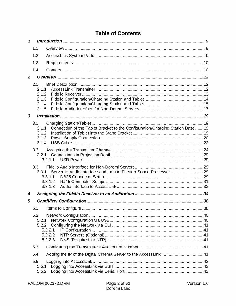
Table of Contents
1 Introduction ...................................................................................................................... 9
1.1 Overview .................................................................................................................... 9
1.2 AccessLink System Parts ........................................................................................... 9
1.3 Requirements ............................................................................................................10
1.4 Contact ......................................................................................................................10
2 Overview ..........................................................................................................................12
2.1 Brief Description ........................................................................................................12 2.1.1 AccessLink Transmitter ..........................................................................................12 2.1.2 Fidelio Receiver .....................................................................................................13 2.1.3 Fidelio Configuration/Charging Station and Tablet .................................................14 2.1.4 Fidelio Configuration/Charging Station and Tablet .................................................15 2.1.5 Fidelio Audio Interface for Non-Doremi Servers .....................................................17
3 Installation .......................................................................................................................19
3.1 Charging Station/Tablet .............................................................................................19 3.1.1 Connection of the Tablet Bracket to the Configuration/Charging Station Base .......19 3.1.2 Installation of Tablet into the Stand Bracket ...........................................................19 3.1.3 Power Supply Connection ......................................................................................20 3.1.4 USB Cable .............................................................................................................22
3.2 Assigning the Transmitter Channel ............................................................................24 3.2.1 Connections in Projection Booth ............................................................................29
3.2.1.1 USB Power ....................................................................................................29
3.3 Fidelio Audio Interface for Non-Doremi Servers .........................................................29 3.3.1 Server to Audio Interface and then to Theater Sound Processor ...........................29
3.3.1.1 DB25 Connector Setup ..................................................................................29 3.3.1.2 RJ45 Connector Setups .................................................................................31 3.3.1.3 Audio Interface to AccessLink ........................................................................32
4 Assigning the Fidelio Receiver to an Auditorium .........................................................34
5 CaptiView Configuration .................................................................................................38
5.1 Items to Configure .....................................................................................................38
5.2 Network Configuration ...............................................................................................40 5.2.1 Network Configuration via USB ..............................................................................40 5.2.2 Configuring the Network via CLI ............................................................................41
5.2.2.1 IP Configuration .............................................................................................41 5.2.2.2 NTP Servers (Optional) ..................................................................................41 5.2.2.3 DNS (Required for NTP) ................................................................................41
5.3 Configuring the Transmitter's Auditorium Number ......................................................41
5.4 Adding the IP of the Digital Cinema Server to the AccessLink ...................................41
5.5 Logging into AccessLink ............................................................................................42 5.5.1 Logging into AccessLink via SSH ..........................................................................42 5.5.2 Logging into AccessLink via Serial Port .................................................................42
FAL.OM.002372.DRM Page 3 of 62 Version 1.6 Doremi Labs
5.6 Upgrading the AccessLink Software ..........................................................................43 5.6.1 FTP Client ..............................................................................................................43 5.6.2 USB Flash Update .................................................................................................43
5.7 Generating a Report ..................................................................................................44 5.7.1 Generating a Report via CLI ..................................................................................44 5.7.2 Generating a Report via USB .................................................................................44
6 Accessibility Track Mapping ..........................................................................................46
6.1 ISDCF/Interop Specs .................................................................................................46
7 Digital Cinema Naming Convention ...............................................................................48
7.1 Appendix 4: Audio Configuration and Narrative Description Track Language ............49
8 Technical Specifications .................................................................................................51
8.1 Fidelio System ...........................................................................................................51
8.2 AccessLink Transmitter .............................................................................................51
8.3 Fidelio Receiver .........................................................................................................51
8.4 Ethernet Connection ..................................................................................................51
9 LED Lights Description ...................................................................................................53
9.1 Fidelio Receiver LEDs ...............................................................................................53
9.2 AccessLink Transmitter Unit LEDs .............................................................................55
10 Appendix A: Wiring Guide ..............................................................................................57
11 Acronyms.........................................................................................................................60
12 Document Revision History ............................................................................................62
FAL.OM.002372.DRM Page 4 of 62 Version 1.6 Doremi Labs
Software License Agreement
The software license agreement can be found at the following location: http://www.doremilabs.com/support/cinema-support/cinema-warranties/
Hardware Warranty
The hardware warranty can be found at the following location: http://www.doremilabs.com/support/cinema-support/cinema-warranties/
FAL.OM.002372.DRM Page 5 of 62 Version 1.6 Doremi Labs
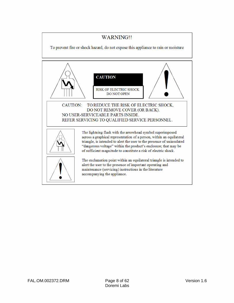
WARNING
THIS DEVICE MUST BE GROUNDED
IMPORTANT
Power requirements for electrical equipment vary from area to area. Please ensure that the Fidelio with AccessLink meets the power requirements in the surrounding area. If in doubt, consult a qualified electrician or a Doremi Labs dealer.
PROTECTING YOURSELF AND THE FIDELIO WITH ACCESSLINK
Only a qualified professional can install the AccessLink. Only use the antenna provided by Doremi Labs.
The AccessLink shall be mounted with a separation distance of at least 20cm from any person (L’AccessLink doit être installé à une distance d’au moins 20cm de toute personne).
The CaptiView transmitter (if connected to the AccessLink), or any other antenna, shall at least be 20cm away from the AccessLink antenna – usage of a USB extension cable will be needed for the CaptiView transmitter connection.
There is a possibility to have noise conducted to Ethernet, Audio and Serial cables. Use cables shorter than 3 meters whenever possible and route cables away from powerful RF noise sources and power cables.
Never touch the AC plug with wet hands. Always disconnect the Fidelio with AccessLink from the power supply by pulling on the plug not the cord. Allow only a Doremi Labs, Inc. dealer or qualified professional engineer to repair or re-assemble the Fidelio with AccessLink. Apart from voiding the warranty, unauthorized engineers might touch live internal parts and receive a serious electric shock. Do not put, or allow anyone to put any object, especially metal objects, into the Fidelio with AccessLink. Use only the provided AC power supply. Never use a DC power supply.
If water or any other liquid is spilled into or onto the Fidelio with AccessLink, disconnect the power and call a Doremi dealer. The unit must be well ventilated and away from direct sunlight. To avoid damage to internal circuitry, as well as the external finish, keep the Fidelio with AccessLink away from direct sources of heat (heater vents, stoves, radiators). Avoid using flammable aerosols near the Fidelio with AccessLink. They can damage the surface area and may ignite. Do not use denatured alcohol, paint thinner or similar chemicals to clean the Fidelio with AccessLink. This can damage the unit.
Modification of this equipment is dangerous and can result in the functions of the Fidelio with AccessLink being impaired. Never attempt to modify the equipment in any way. In order to ensure optimum performance of the Fidelio with AccessLink, select the setup location carefully and make sure the equipment is used properly. Avoid setting up the Fidelio with AccessLink in the following locations:
In a humid or dusty environment.
In a room with poor ventilation.
In an extremely hot or cold environment.
FAL.OM.002372.DRM Page 6 of 62 Version 1.6 Doremi Labs
FCC Warning - AccessLink
Be aware that any change or modification not expressly approved by Doremi Labs could void the user's authority to operate the equipment.
This device complies with part 15 of the FCC Rules. Operation is subject to the following two conditions: (1) This device may not cause harmful interference, and (2) this device must accept any interference received, including interference that may cause undesired operation.
Note: This equipment has been tested and found to comply with the limits for a Class A digital device, pursuant to part 15 of the FCC Rules. These limits are designed to provide reasonable protection against harmful interference when the equipment is operated in a commercial environment. This equipment generates, uses, and can radiate radio frequency energy and, if not installed and used in accordance with the instruction manual, may cause harmful interference to radio communications. Operation of this equipment in a residential area is likely to cause harmful interference in which case the user will be required to correct the interference at his own expense.
IC Statement – AccessLink
This device complies with Industry Canada licence-exempt RSS standard(s). Operation is subject to the following two conditions: (1) this device may not cause interference, and (2) this device must accept any interference, including interference that may cause undesired operation of the device. Le présent appareil est conforme aux CNR d'Industrie Canada applicables aux appareils radio exempts de licence. L'exploitation est autorisée aux deux conditions suivantes : (1) l'appareil ne doit pas produire de brouillage, et (2) l'utilisateur de l'appareil doit accepter tout brouillage radioélectrique subi, même si le brouillage est susceptible d'en compromettre le fonctionnement.
Under Industry Canada regulations, this radio transmitter may only operate using an antenna of a type and maximum (or lesser) gain approved for the transmitter by Industry Canada. To reduce potential radio interference to other users, the antenna type and its gain should be so chosen that the equivalent isotropically radiated power (e.i.r.p.) is not more than that necessary for successful communication. Conformément à la réglementation d'Industrie Canada, le présent émetteur radio peut fonctionner avec une antenne d'un type et d'un gain maximal (ou inférieur) approuvé pour l'émetteur par Industrie Canada. Dans le but de réduire les risques de brouillage radioélectrique à l'intention des autres utilisateurs, il faut choisir le type d'antenne et son gain de sorte que la puissance isotrope rayonnée équivalente (p.i.r.e.) ne dépasse pas l'intensité nécessaire à l'établissement d'une communication satisfaisante.
FAL.OM.002372.DRM Page 7 of 62 Version 1.6 Doremi Labs
The AccessLink (FCC ID: 2ADHX-ACCESSLINK, IC ID: 12467A-ACCESSLINK) radio transmitter has been approved by Industry Canada to operate with the antenna type listed below with the maximum permissible gain indicated. Antenna types not included in this list, having a gain greater than the maximum gain indicated, are strictly prohibited for use with this device.
Antenna: Pulse Part Number: SPDA24850/1900, Maximum Gain: 3dB
FAL.OM.002372.DRM Page 8 of 62 Version 1.6 Doremi Labs
FAL.OM.002372.DRM Page 9 of 62 Version 1.6 Doremi Labs
1 Introduction
1.1 Overview
The AccessLink is an audio distribution system that is used with non-Doremi cinema servers to provide two stereo channels from a single transmitter unit to a number of receiver units. AccessLink is designed to interface with the Fidelio system to enhance and assist people who are visually and/or hearing impaired in a motion picture theater. This manual will guide you through the steps necessary to physically set up and connect the AccessLink device. The entire AccessLink setup consists of a Transmitter, Fidelio Receiver, Charging/Configuration Station, Touch Screen Tablet, Audio Interface Box and Headset. The Fidelio Receiver device docks to the charger, which can be used for multiple purposes including:
Recharging the battery
Configuration
Upgrading firmware
Production tests
1.2 AccessLink System Parts
AccessLink Transmitter Box (Doremi P/N: ACCESSLINK)
AccessLink Transmitter Antenna (Doremi P/N: FIDELIO-TX-ANT)
2 meter USB cable A-B (Doremi P/N: CBL-USBA-USBB-6)
Fidelio Audio Interface Box (FIS)
o Doremi P/N for Doremi Servers: FIDELIO-AI (DB25 or RJ45 setups)
o Doremi P/N for GDC: FIDELIO-AI (DB25 or RJ45 setups)
o Doremi P/N for Sony: FIDELIO-AI-S (DB25 only setups)
o Doremi P/N for Dolby: FIDELIO-AI-S (DB25 only setups)
1 Meter DB25 cable, M-F, 1-to-1 pin out (Doremi P/N: CBL-DB25M-DB25F-2.5)
Fidelio Receiver with Belt-clip (Doremi P/N: FIDELIO-RX)
Fidelio Headphone (Doremi P/N: FIDELIO-RX-HP)
Fidelio Charging Station (Doremi P/N: FIDELIO-WAC)
7” Tablet Mounting Bracket (Doremi P/N: MTL-FIDELIO-WAC-BRTS)
(4) - M3x6 Black Flat Head Machine Screws (Doremi P/N: M3x6MM-BFH)
4” Nylon tie-wrap, black (Doremi P/N: CBL-TIE-4IN)
(1) - 7” Touchscreen Tablet Computer (v1.1.2 or v2.2.0) – FIDELIO-TS
(1) – For Tablet v1.1.2 - USB Cable, Mini A - Type A - No Part Number
For Tablet v2.2.0 - USB Cable, Micro B – Type A–CBL-FIDELIO-TS-MICROB-AF
5V Power Supply with dual connectors (Doremi P/N: PS-HDVI)
AC Power Cable (Power Cable)
FAL.OM.002372.DRM Page 10 of 62 Version 1.6 Doremi Labs
1.3 Requirements
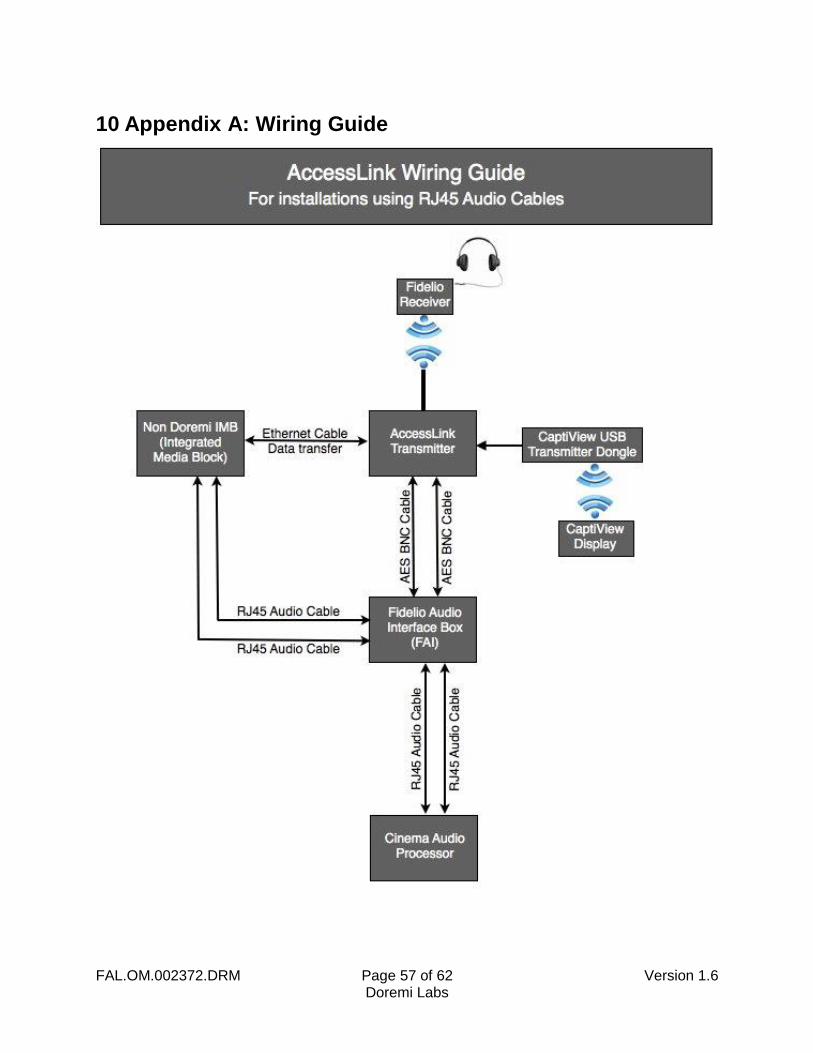
The installer will need to provide two (2) BNC to BNC cables for each AccessLink Transmitter being installed at the complex. The length of these cables will depend on your specific installation requirement. Specifically, the distance depends on where the transmitter will be from the Fidelio Audio Interface box.
1.4 Contact
If in need of help or assistance, please contact Doremi Labs Technical Services: USA 24/7 Technical Services line: + 1-866-484-4004 Technical Services Email: [email protected] Europe 24/7 Technical Services line: + 33 (0) 492-952-847 Technical Services Link: http://support.doremitechno.org/ticketing Japan Technical Services line: + 044-966-4855 Technical Services Email: [email protected] Australia ~ China ~ India ~ Indonesia ~ Korea ~ Malaysia ~ New Zealand ~ Philippines ~ Singapore ~ Taiwan ~ Thailand Technical Services Email: [email protected]

FAL.OM.002372.DRM Page 11 of 62 Version 1.6 Doremi Labs
This page has been intentionally left blank.
FAL.OM.002372.DRM Page 12 of 62 Version 1.6 Doremi Labs
2 Overview
2.1 Brief Description
The following is a brief description of each of the components, with pictures, that make up the AccessLink setup. Begin the installation process by carefully unwrapping and removing all AccessLink and Fidelio components from their boxes. Double-check and confirm that all the parts and components are present.
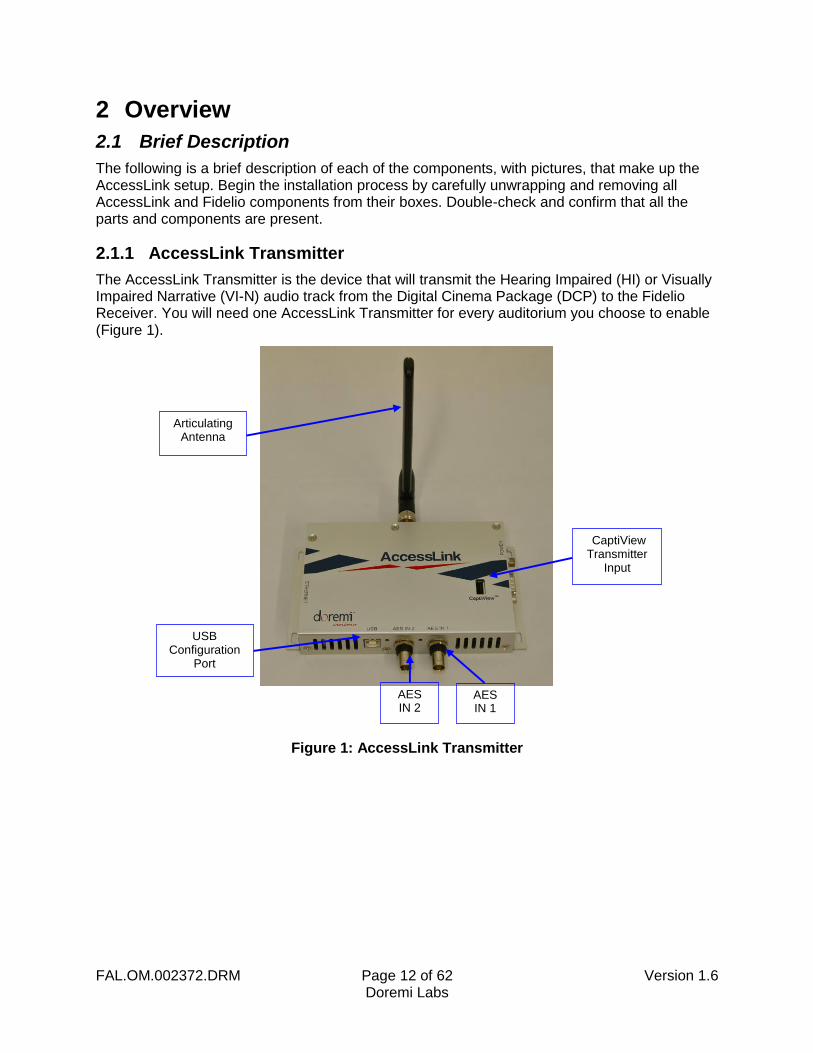
2.1.1 AccessLink Transmitter
The AccessLink Transmitter is the device that will transmit the Hearing Impaired (HI) or Visually Impaired Narrative (VI-N) audio track from the Digital Cinema Package (DCP) to the Fidelio Receiver. You will need one AccessLink Transmitter for every auditorium you choose to enable (Figure 1).
Figure 1: AccessLink Transmitter
CaptiView Transmitter
Input
AES IN 1
AES IN 2
Articulating Antenna
USB Configuration
Port
FAL.OM.002372.DRM Page 13 of 62 Version 1.6 Doremi Labs
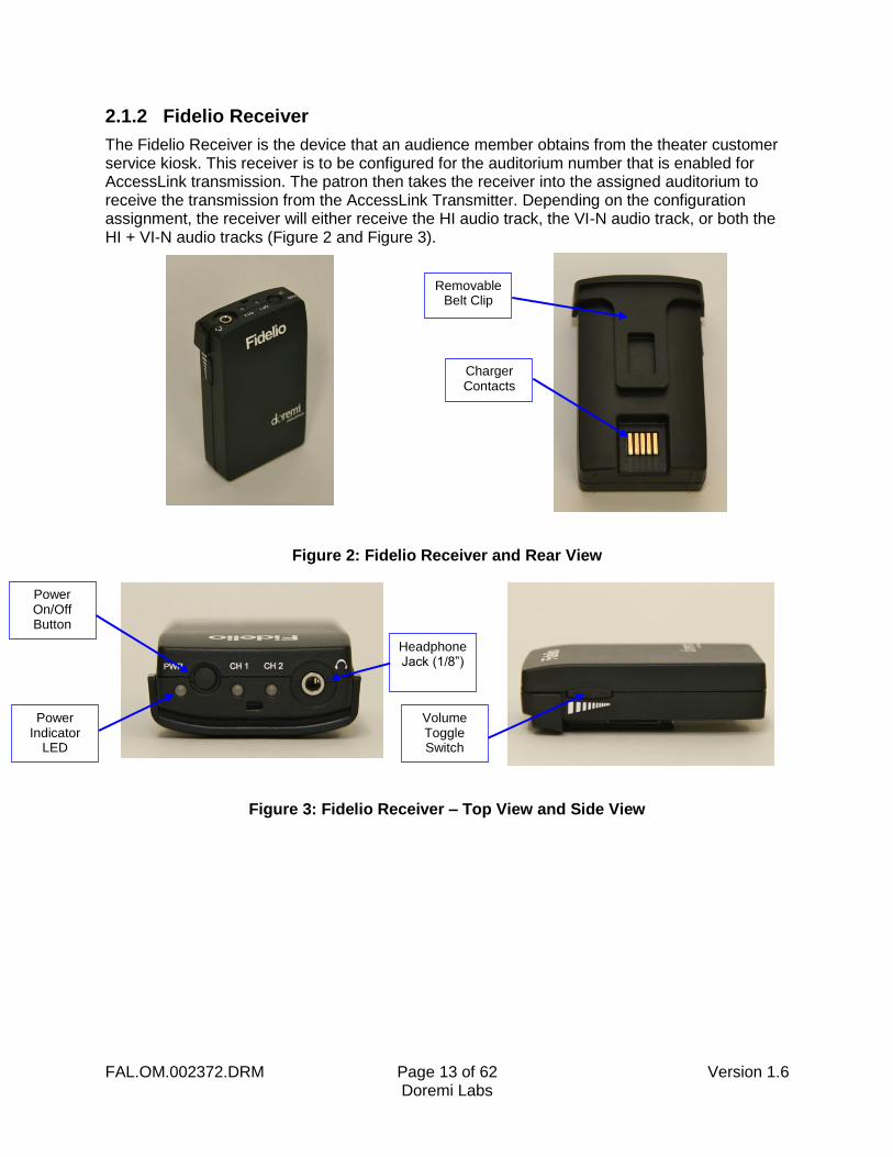
2.1.2 Fidelio Receiver
The Fidelio Receiver is the device that an audience member obtains from the theater customer service kiosk. This receiver is to be configured for the auditorium number that is enabled for AccessLink transmission. The patron then takes the receiver into the assigned auditorium to receive the transmission from the AccessLink Transmitter. Depending on the configuration assignment, the receiver will either receive the HI audio track, the VI-N audio track, or both the HI + VI-N audio tracks (Figure 2 and Figure 3).
Figure 2: Fidelio Receiver and Rear View
Figure 3: Fidelio Receiver – Top View and Side View
Removable Belt Clip
Charger Contacts
Volume Toggle Switch
Power On/Off Button
Power Indicator
LED
Headphone Jack (1/8”)
FAL.OM.002372.DRM Page 14 of 62 Version 1.6 Doremi Labs
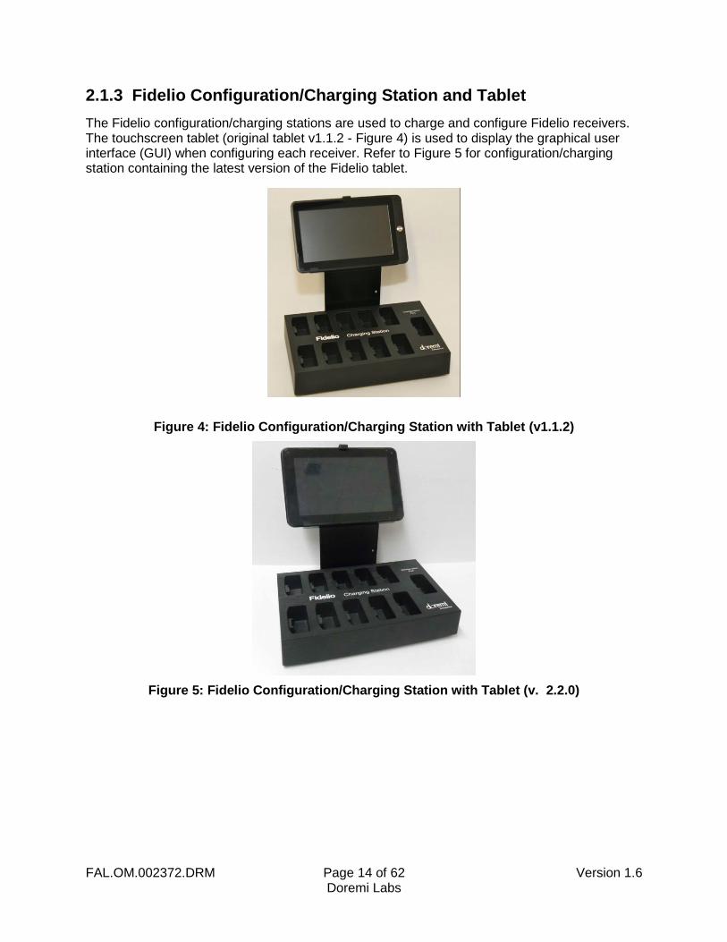
2.1.3 Fidelio Configuration/Charging Station and Tablet
The Fidelio configuration/charging stations are used to charge and configure Fidelio receivers. The touchscreen tablet (original tablet v1.1.2 - Figure 4) is used to display the graphical user interface (GUI) when configuring each receiver. Refer to Figure 5 for configuration/charging station containing the latest version of the Fidelio tablet.
Figure 4: Fidelio Configuration/Charging Station with Tablet (v1.1.2)
Figure 5: Fidelio Configuration/Charging Station with Tablet (v. 2.2.0)
FAL.OM.002372.DRM Page 15 of 62 Version 1.6 Doremi Labs
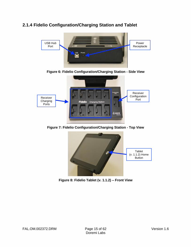
2.1.4 Fidelio Configuration/Charging Station and Tablet
Figure 6: Fidelio Configuration/Charging Station - Side View
Figure 7: Fidelio Configuration/Charging Station - Top View
Figure 8: Fidelio Tablet (v. 1.1.2) – Front View
USB Hub Port
Power Receptacle
Receiver Charging
Ports
Receiver Configuration
Port
Tablet (v. 1.1.2) Home
Button
FAL.OM.002372.DRM Page 16 of 62 Version 1.6 Doremi Labs
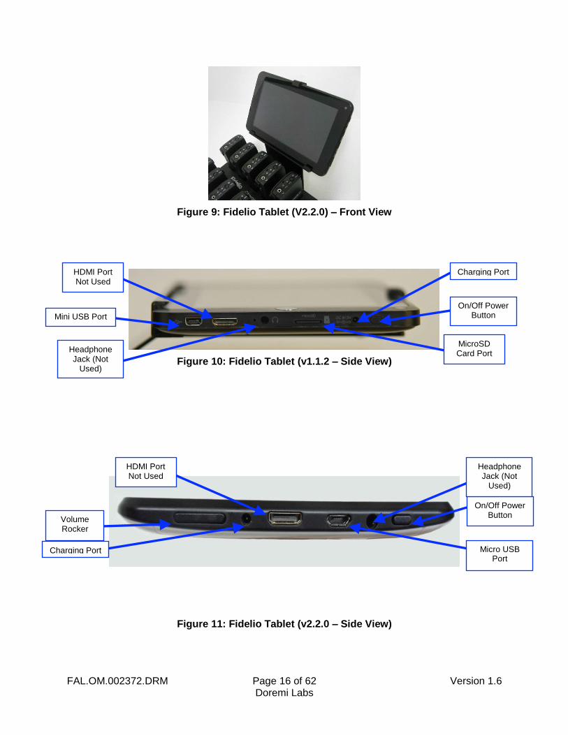
Figure 9: Fidelio Tablet (V2.2.0) – Front View
Figure 10: Fidelio Tablet (v1.1.2 – Side View)
Figure 11: Fidelio Tablet (v2.2.0 – Side View)
Mini USB Port
Headphone Jack (Not
Used)
On/Off Power Button
MicroSD Card Port
HDMI Port Not Used
Volume Rocker
On/Off Power Button
Headphone Jack (Not
Used)
HDMI Port Not Used
Micro USB Port
Charging Port
Charging Port
FAL.OM.002372.DRM Page 17 of 62 Version 1.6 Doremi Labs
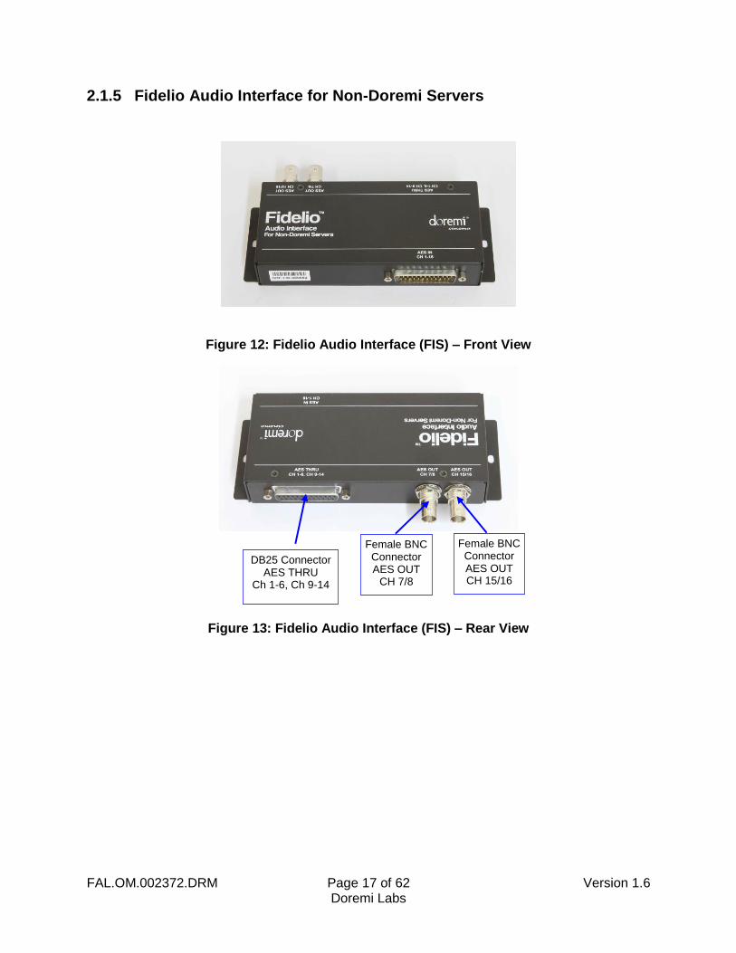
2.1.5 Fidelio Audio Interface for Non-Doremi Servers
Figure 12: Fidelio Audio Interface (FIS) – Front View
Figure 13: Fidelio Audio Interface (FIS) – Rear View
DB25 Connector AES THRU
Ch 1-6, Ch 9-14
Female BNC Connector AES OUT CH 15/16
Female BNC Connector AES OUT
CH 7/8

FAL.OM.002372.DRM Page 18 of 62 Version 1.6 Doremi Labs
This page has been intentionally left blank.
FAL.OM.002372.DRM Page 19 of 62 Version 1.6 Doremi Labs
3 Installation Follow the steps below to set up the AccessLink and Fidelio System.
For the connection diagram, please refer to Section 10.
3.1 Charging Station/Tablet
You will need to first connect the touchscreen tablet to the Fidelio Charging/Configuration Base using the tablet bracket.
3.1.1 Connection of the Tablet Bracket to the Configuration/Charging Station Base
Place the Fidelio Configuration/Charging Station Base upside down near the edge of a table so that the Tablet bracket can hang down and sit flush with the bottom of the base.
Line up the four (4) holes of the tablet mounting bracket to the four (4) holes of the Charging/Configuration Base.
Using a Phillips screwdriver, carefully secure the Tablet Mounting Bracket to the Charging/Configuration Base using the four (4) M3x6 Black Flat Head Machine Screws provided.
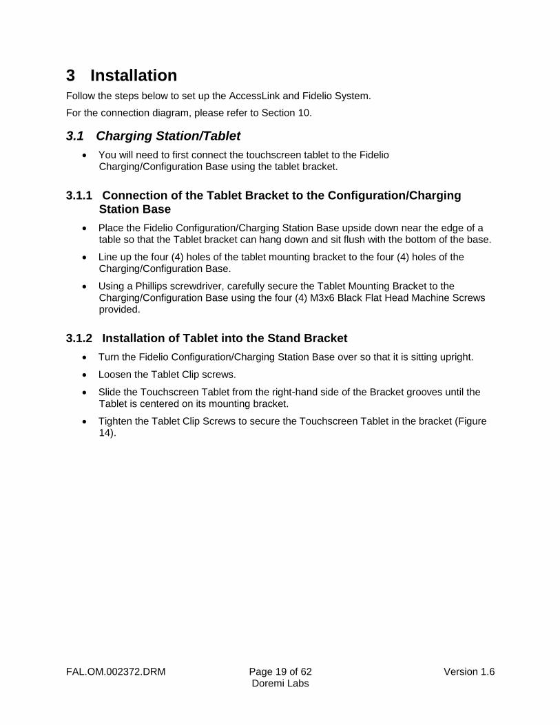
3.1.2 Installation of Tablet into the Stand Bracket
Turn the Fidelio Configuration/Charging Station Base over so that it is sitting upright.
Loosen the Tablet Clip screws.
Slide the Touchscreen Tablet from the right-hand side of the Bracket grooves until the Tablet is centered on its mounting bracket.
Tighten the Tablet Clip Screws to secure the Touchscreen Tablet in the bracket (Figure 14).
FAL.OM.002372.DRM Page 20 of 62 Version 1.6 Doremi Labs
Figure 14: Tablet Rear View
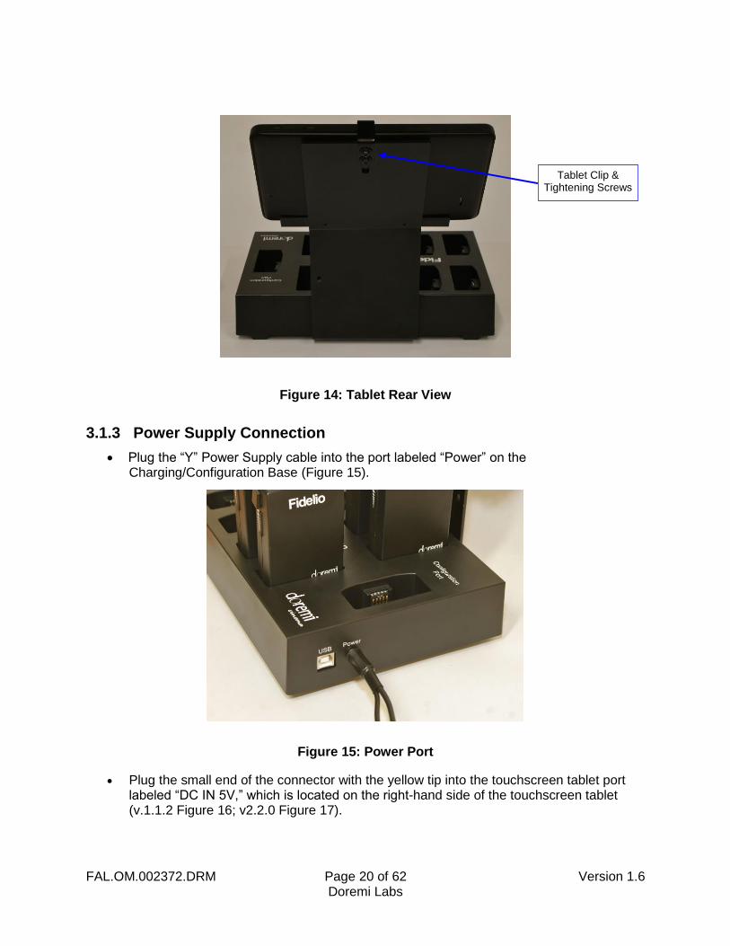
3.1.3 Power Supply Connection
Plug the “Y” Power Supply cable into the port labeled “Power” on the Charging/Configuration Base (Figure 15).
Figure 15: Power Port
Plug the small end of the connector with the yellow tip into the touchscreen tablet port labeled “DC IN 5V,” which is located on the right-hand side of the touchscreen tablet (v.1.1.2 Figure 16; v2.2.0 Figure 17).
Tablet Clip & Tightening Screws

FAL.OM.002372.DRM Page 21 of 62 Version 1.6 Doremi Labs
Figure 16: Tablet (v1.1.2) Power Connector
Figure 17: Tablet (v2.2.0) Power Connector
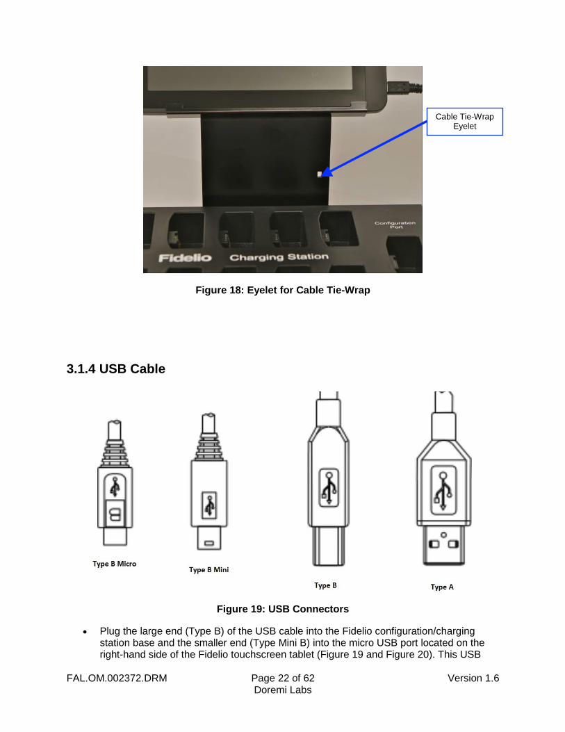
Using a 4” Nylon black tie-wrap provided, slip the tie-wrap though the eyelet (Figure 18) to secure the cable to the tablet mounting bracket.
DC IN 5V Tablet Power
Connector
DC IN 5V Tablet Power
Cable
Micro USB Cable
Micro USB Cable
FAL.OM.002372.DRM Page 22 of 62 Version 1.6 Doremi Labs
Figure 18: Eyelet for Cable Tie-Wrap
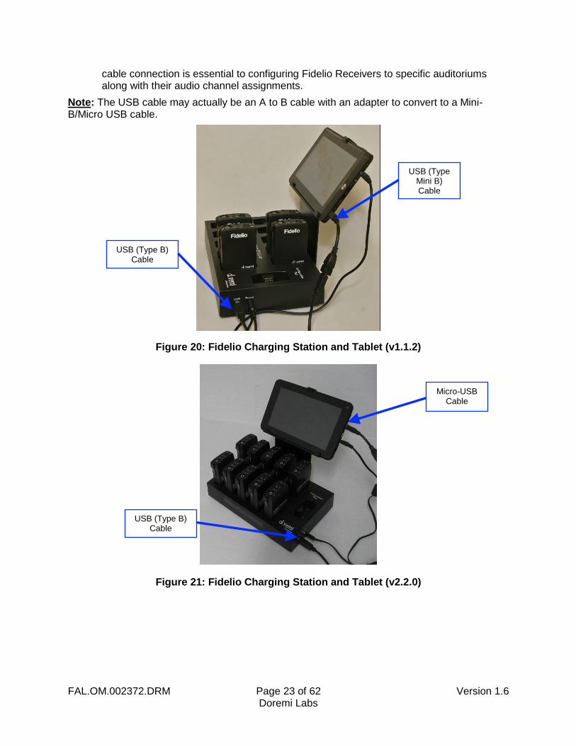
3.1.4 USB Cable
Figure 19: USB Connectors
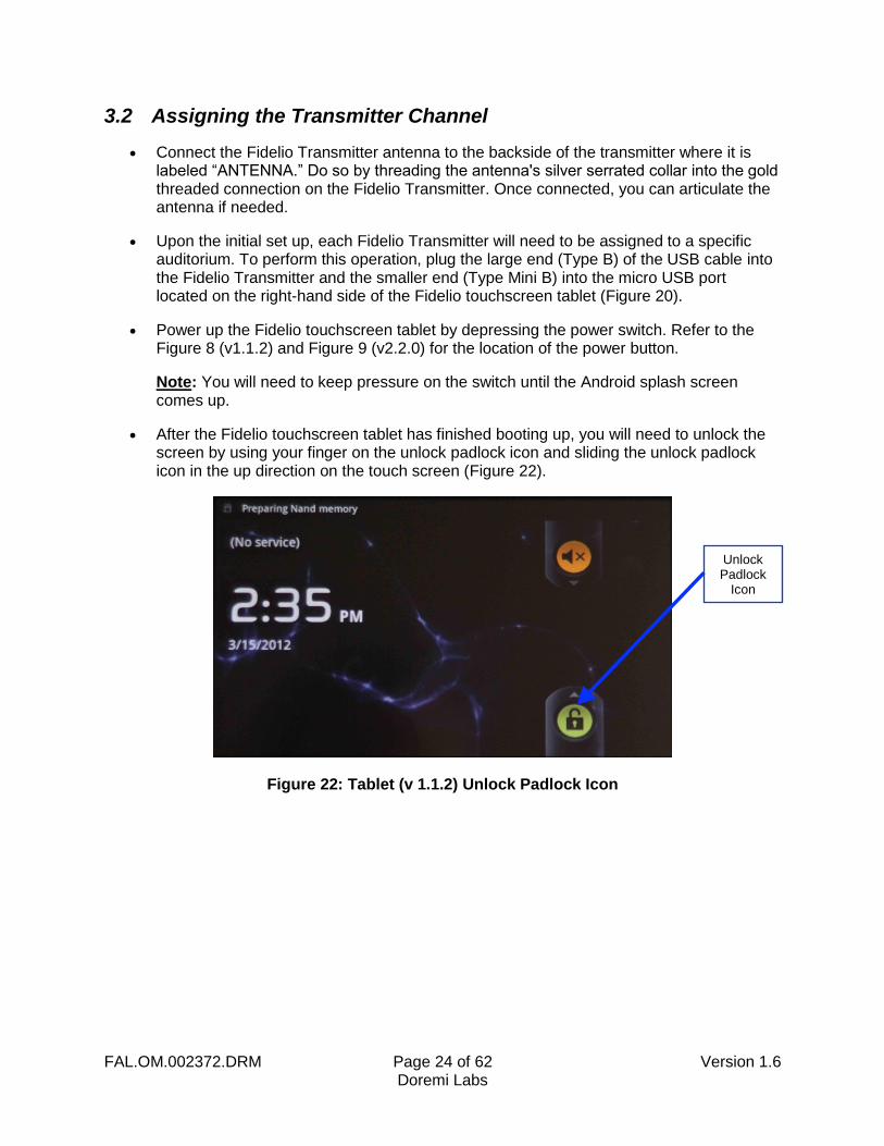
Plug the large end (Type B) of the USB cable into the Fidelio configuration/charging station base and the smaller end (Type Mini B) into the micro USB port located on the right-hand side of the Fidelio touchscreen tablet (Figure 19 and Figure 20). This USB
Cable Tie-Wrap Eyelet
FAL.OM.002372.DRM Page 23 of 62 Version 1.6 Doremi Labs
cable connection is essential to configuring Fidelio Receivers to specific auditoriums along with their audio channel assignments.
Note: The USB cable may actually be an A to B cable with an adapter to convert to a Mini-B/Micro USB cable.
Figure 20: Fidelio Charging Station and Tablet (v1.1.2)
Figure 21: Fidelio Charging Station and Tablet (v2.2.0)
USB (Type B) Cable
USB (Type Mini B) Cable
Micro-USB Cable
USB (Type B) Cable
FAL.OM.002372.DRM Page 24 of 62 Version 1.6 Doremi Labs
3.2 Assigning the Transmitter Channel
Connect the Fidelio Transmitter antenna to the backside of the transmitter where it is labeled “ANTENNA.” Do so by threading the antenna's silver serrated collar into the gold threaded connection on the Fidelio Transmitter. Once connected, you can articulate the antenna if needed.
Upon the initial set up, each Fidelio Transmitter will need to be assigned to a specific auditorium. To perform this operation, plug the large end (Type B) of the USB cable into the Fidelio Transmitter and the smaller end (Type Mini B) into the micro USB port located on the right-hand side of the Fidelio touchscreen tablet (Figure 20).
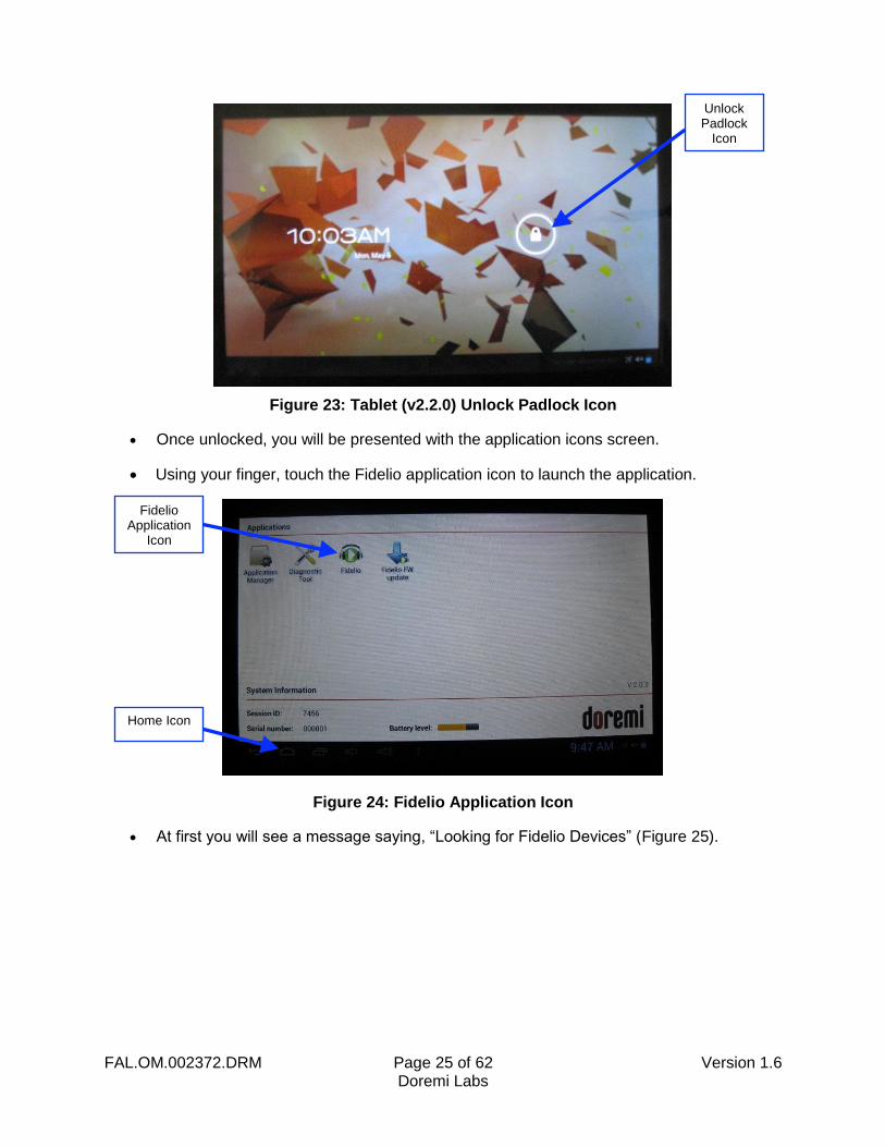
Power up the Fidelio touchscreen tablet by depressing the power switch. Refer to the Figure 8 (v1.1.2) and Figure 9 (v2.2.0) for the location of the power button.
Note: You will need to keep pressure on the switch until the Android splash screen comes up.
After the Fidelio touchscreen tablet has finished booting up, you will need to unlock the screen by using your finger on the unlock padlock icon and sliding the unlock padlock icon in the up direction on the touch screen (Figure 22).
Figure 22: Tablet (v 1.1.2) Unlock Padlock Icon
Unlock Padlock
Icon
FAL.OM.002372.DRM Page 25 of 62 Version 1.6 Doremi Labs
Figure 23: Tablet (v2.2.0) Unlock Padlock Icon
Once unlocked, you will be presented with the application icons screen.
Using your finger, touch the Fidelio application icon to launch the application.
Figure 24: Fidelio Application Icon
At first you will see a message saying, “Looking for Fidelio Devices” (Figure 25).
Fidelio Application
Icon
Home Icon
Unlock Padlock
Icon
FAL.OM.002372.DRM Page 26 of 62 Version 1.6 Doremi Labs
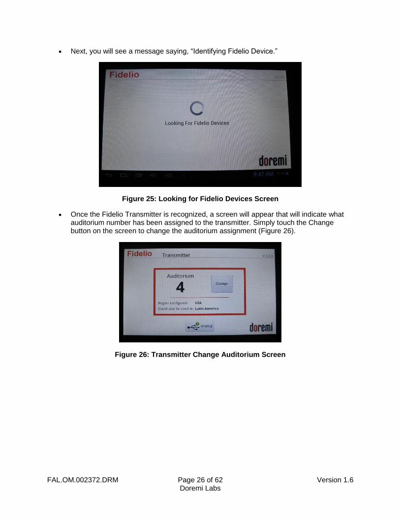
Next, you will see a message saying, “Identifying Fidelio Device.”
Figure 25: Looking for Fidelio Devices Screen
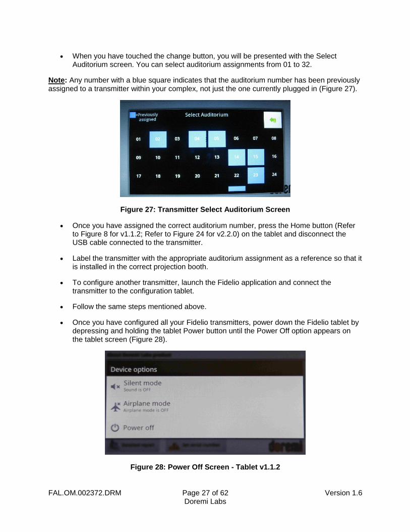
Once the Fidelio Transmitter is recognized, a screen will appear that will indicate what auditorium number has been assigned to the transmitter. Simply touch the Change button on the screen to change the auditorium assignment (Figure 26).
Figure 26: Transmitter Change Auditorium Screen
FAL.OM.002372.DRM Page 27 of 62 Version 1.6 Doremi Labs
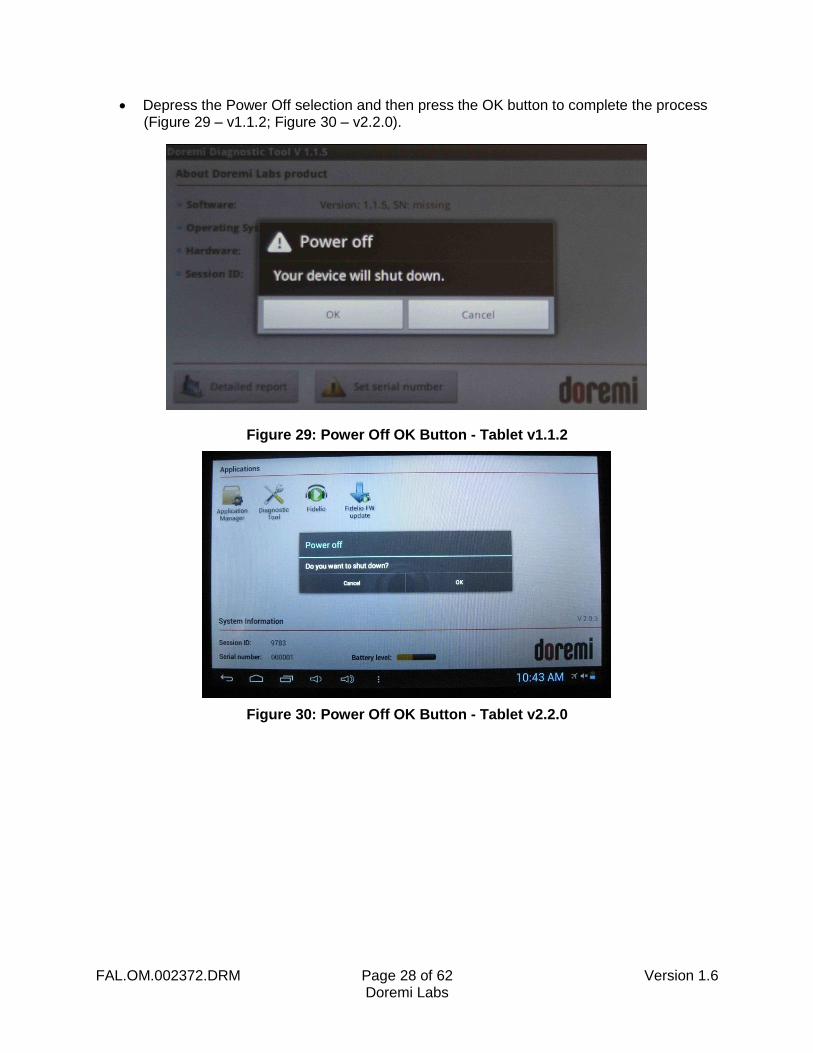
When you have touched the change button, you will be presented with the Select Auditorium screen. You can select auditorium assignments from 01 to 32.
Note: Any number with a blue square indicates that the auditorium number has been previously assigned to a transmitter within your complex, not just the one currently plugged in (Figure 27).
Figure 27: Transmitter Select Auditorium Screen
Once you have assigned the correct auditorium number, press the Home button (Refer to Figure 8 for v1.1.2; Refer to Figure 24 for v2.2.0) on the tablet and disconnect the USB cable connected to the transmitter.
Label the transmitter with the appropriate auditorium assignment as a reference so that it is installed in the correct projection booth.
To configure another transmitter, launch the Fidelio application and connect the transmitter to the configuration tablet.
Follow the same steps mentioned above.
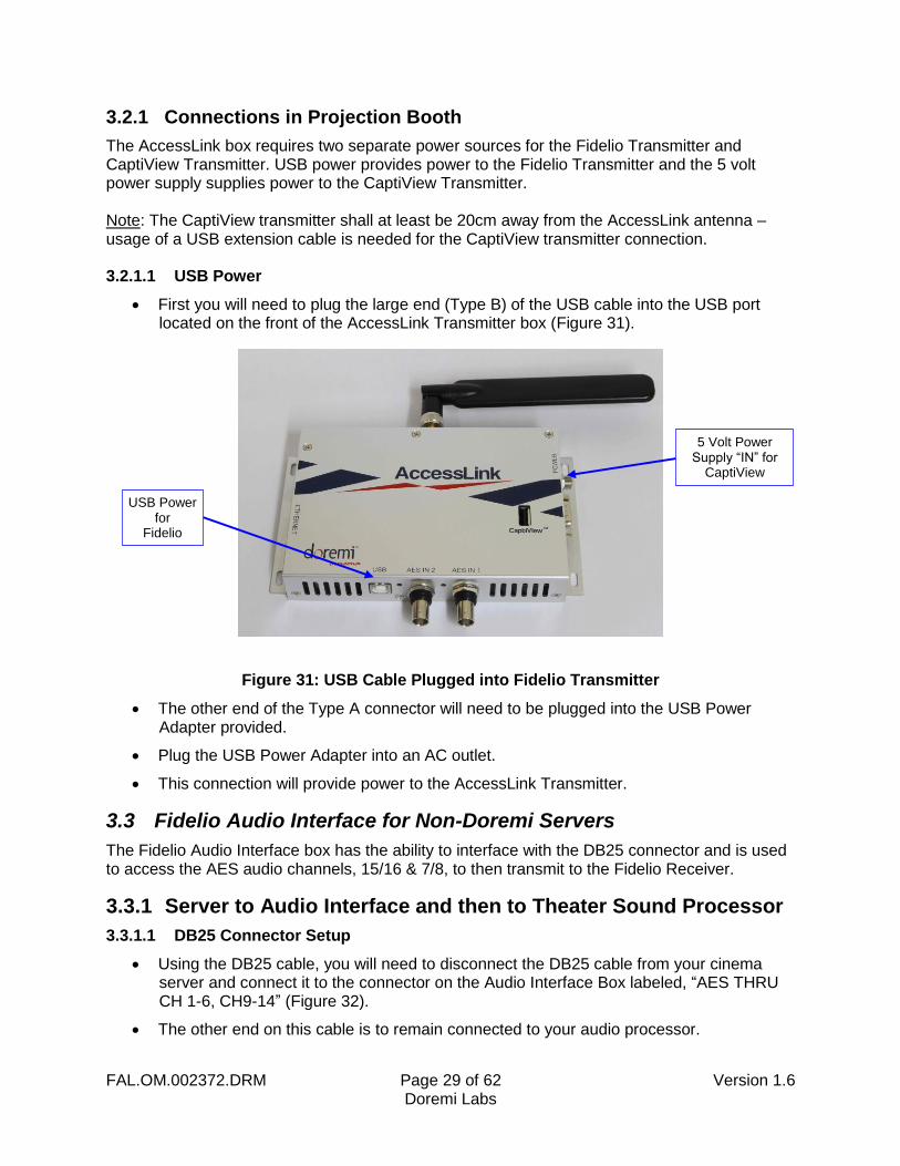
Once you have configured all your Fidelio transmitters, power down the Fidelio tablet by depressing and holding the tablet Power button until the Power Off option appears on the tablet screen (Figure 28).
Figure 28: Power Off Screen - Tablet v1.1.2
FAL.OM.002372.DRM Page 28 of 62 Version 1.6 Doremi Labs
Depress the Power Off selection and then press the OK button to complete the process (Figure 29 – v1.1.2; Figure 30 – v2.2.0).
Figure 29: Power Off OK Button - Tablet v1.1.2
Figure 30: Power Off OK Button - Tablet v2.2.0
FAL.OM.002372.DRM Page 29 of 62 Version 1.6 Doremi Labs
3.2.1 Connections in Projection Booth
The AccessLink box requires two separate power sources for the Fidelio Transmitter and CaptiView Transmitter. USB power provides power to the Fidelio Transmitter and the 5 volt power supply supplies power to the CaptiView Transmitter. Note: The CaptiView transmitter shall at least be 20cm away from the AccessLink antenna – usage of a USB extension cable is needed for the CaptiView transmitter connection. 3.2.1.1 USB Power
First you will need to plug the large end (Type B) of the USB cable into the USB port located on the front of the AccessLink Transmitter box (Figure 31).
Figure 31: USB Cable Plugged into Fidelio Transmitter
The other end of the Type A connector will need to be plugged into the USB Power Adapter provided.
Plug the USB Power Adapter into an AC outlet.
This connection will provide power to the AccessLink Transmitter.
3.3 Fidelio Audio Interface for Non-Doremi Servers
The Fidelio Audio Interface box has the ability to interface with the DB25 connector and is used to access the AES audio channels, 15/16 & 7/8, to then transmit to the Fidelio Receiver.
3.3.1 Server to Audio Interface and then to Theater Sound Processor
3.3.1.1 DB25 Connector Setup
Using the DB25 cable, you will need to disconnect the DB25 cable from your cinema server and connect it to the connector on the Audio Interface Box labeled, “AES THRU CH 1-6, CH9-14” (Figure 32).
The other end on this cable is to remain connected to your audio processor.
5 Volt Power Supply “IN” for
CaptiView
USB Power for
Fidelio
FAL.OM.002372.DRM Page 30 of 62 Version 1.6 Doremi Labs
Using the short DB25 cable provided, connect one end into the AES OUT on the server and the other end into the AES IN connector on the Audio Interface box.
FAL.OM.002372.DRM Page 31 of 62 Version 1.6 Doremi Labs
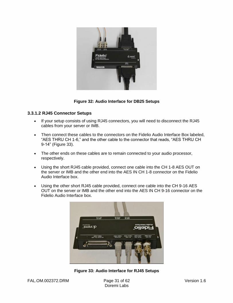
Figure 32: Audio Interface for DB25 Setups
3.3.1.2 RJ45 Connector Setups
If your setup consists of using RJ45 connectors, you will need to disconnect the RJ45 cables from your server or IMB.
Then connect these cables to the connectors on the Fidelio Audio Interface Box labeled, “AES THRU CH 1-6,” and the other cable to the connector that reads, “AES THRU CH 9-14” (Figure 33).
The other ends on these cables are to remain connected to your audio processor, respectively.
Using the short RJ45 cable provided, connect one cable into the CH 1-8 AES OUT on the server or IMB and the other end into the AES IN CH 1-8 connector on the Fidelio Audio Interface box.
Using the other short RJ45 cable provided, connect one cable into the CH 9-16 AES OUT on the server or IMB and the other end into the AES IN CH 9-16 connector on the Fidelio Audio Interface box.
Figure 33: Audio Interface for RJ45 Setups
FAL.OM.002372.DRM Page 32 of 62 Version 1.6 Doremi Labs
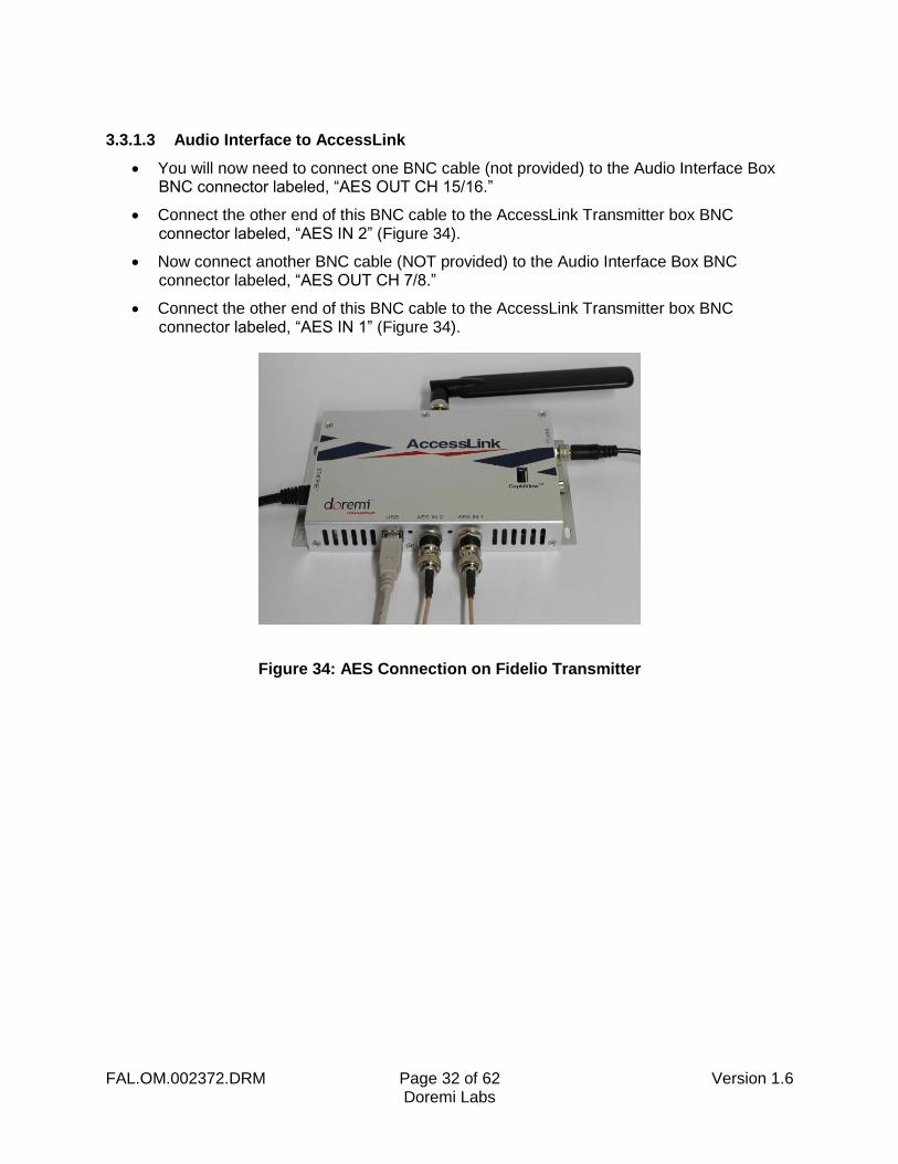
3.3.1.3 Audio Interface to AccessLink
You will now need to connect one BNC cable (not provided) to the Audio Interface Box BNC connector labeled, “AES OUT CH 15/16.”
Connect the other end of this BNC cable to the AccessLink Transmitter box BNC connector labeled, “AES IN 2” (Figure 34).
Now connect another BNC cable (NOT provided) to the Audio Interface Box BNC connector labeled, “AES OUT CH 7/8.”
Connect the other end of this BNC cable to the AccessLink Transmitter box BNC connector labeled, “AES IN 1” (Figure 34).
Figure 34: AES Connection on Fidelio Transmitter

FAL.OM.002372.DRM Page 33 of 62 Version 1.6 Doremi Labs
This page has been intentionally left blank.
FAL.OM.002372.DRM Page 34 of 62 Version 1.6 Doremi Labs
4 Assigning the Fidelio Receiver to an Auditorium
First you will need to plug the large end (Type B) of the USB cable into the USB port located on the right-hand side of the Fidelio charging station base and the smaller end (Mini A) into the micro USB port located on the right-hand side of the Fidelio touchscreen tablet (Figure 20).
Power up the Fidelio touchscreen tablet by depressing the power switch located on the top right-hand side of the tablet (Figure 10).
Note: You will need to keep pressure on the switch until the Android splash screen comes up.
After the Fidelio touchscreen tablet has finished booting up, you will need to unlock the screen by using your finger on the unlock padlock icon and sliding up on the touch screen (Figure 22).
Once unlocked, you will be presented with the Fidelio application icon screen.
Using your finger, touch the Fidelio application icon to launch the application (Figure 24).
The tablet will display a message saying, “Looking for Fidelio Devices” (Figure 25).
Place a Fidelio Receiver into the port labeled, “Configuration Port,” on the Fidelio charging station base.
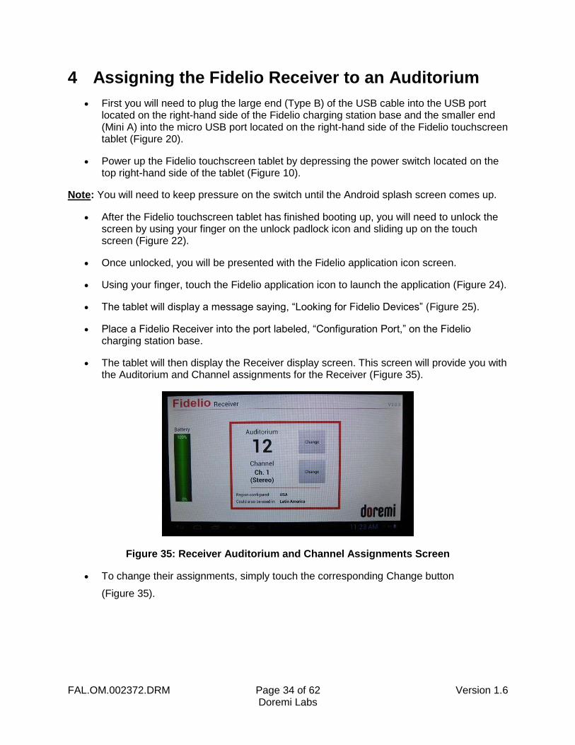
The tablet will then display the Receiver display screen. This screen will provide you with the Auditorium and Channel assignments for the Receiver (Figure 35).
Figure 35: Receiver Auditorium and Channel Assignments Screen
To change their assignments, simply touch the corresponding Change button
(Figure 35).
FAL.OM.002372.DRM Page 35 of 62 Version 1.6 Doremi Labs
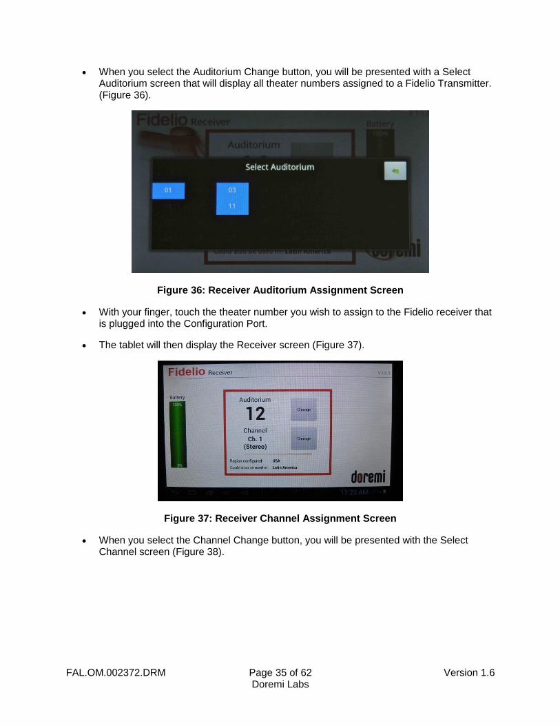
When you select the Auditorium Change button, you will be presented with a Select Auditorium screen that will display all theater numbers assigned to a Fidelio Transmitter. (Figure 36).
Figure 36: Receiver Auditorium Assignment Screen
With your finger, touch the theater number you wish to assign to the Fidelio receiver that is plugged into the Configuration Port.
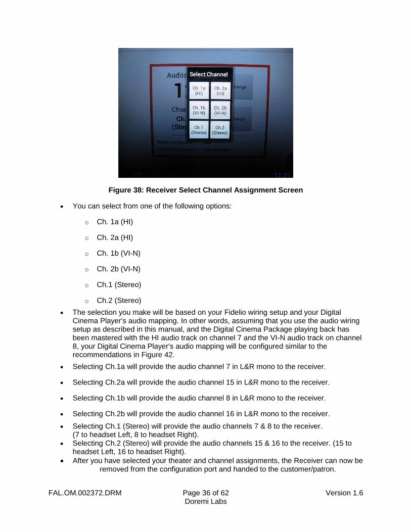
The tablet will then display the Receiver screen (Figure 37).
Figure 37: Receiver Channel Assignment Screen
When you select the Channel Change button, you will be presented with the Select Channel screen (Figure 38).
FAL.OM.002372.DRM Page 36 of 62 Version 1.6 Doremi Labs
Figure 38: Receiver Select Channel Assignment Screen
You can select from one of the following options:
o Ch. 1a (HI)
o Ch. 2a (HI)
o Ch. 1b (VI-N)
o Ch. 2b (VI-N)
o Ch.1 (Stereo)
o Ch.2 (Stereo)
The selection you make will be based on your Fidelio wiring setup and your Digital Cinema Player's audio mapping. In other words, assuming that you use the audio wiring setup as described in this manual, and the Digital Cinema Package playing back has been mastered with the HI audio track on channel 7 and the VI-N audio track on channel 8, your Digital Cinema Player's audio mapping will be configured similar to the recommendations in Figure 42.
Selecting Ch.1a will provide the audio channel 7 in L&R mono to the receiver.
Selecting Ch.2a will provide the audio channel 15 in L&R mono to the receiver.
Selecting Ch.1b will provide the audio channel 8 in L&R mono to the receiver.
Selecting Ch.2b will provide the audio channel 16 in L&R mono to the receiver.
Selecting Ch.1 (Stereo) will provide the audio channels 7 & 8 to the receiver. (7 to headset Left, 8 to headset Right).
Selecting Ch.2 (Stereo) will provide the audio channels 15 & 16 to the receiver. (15 to headset Left, 16 to headset Right).
After you have selected your theater and channel assignments, the Receiver can now be removed from the configuration port and handed to the customer/patron.

FAL.OM.002372.DRM Page 37 of 62 Version 1.6 Doremi Labs
This page has been intentionally left blank.
FAL.OM.002372.DRM Page 38 of 62 Version 1.6 Doremi Labs
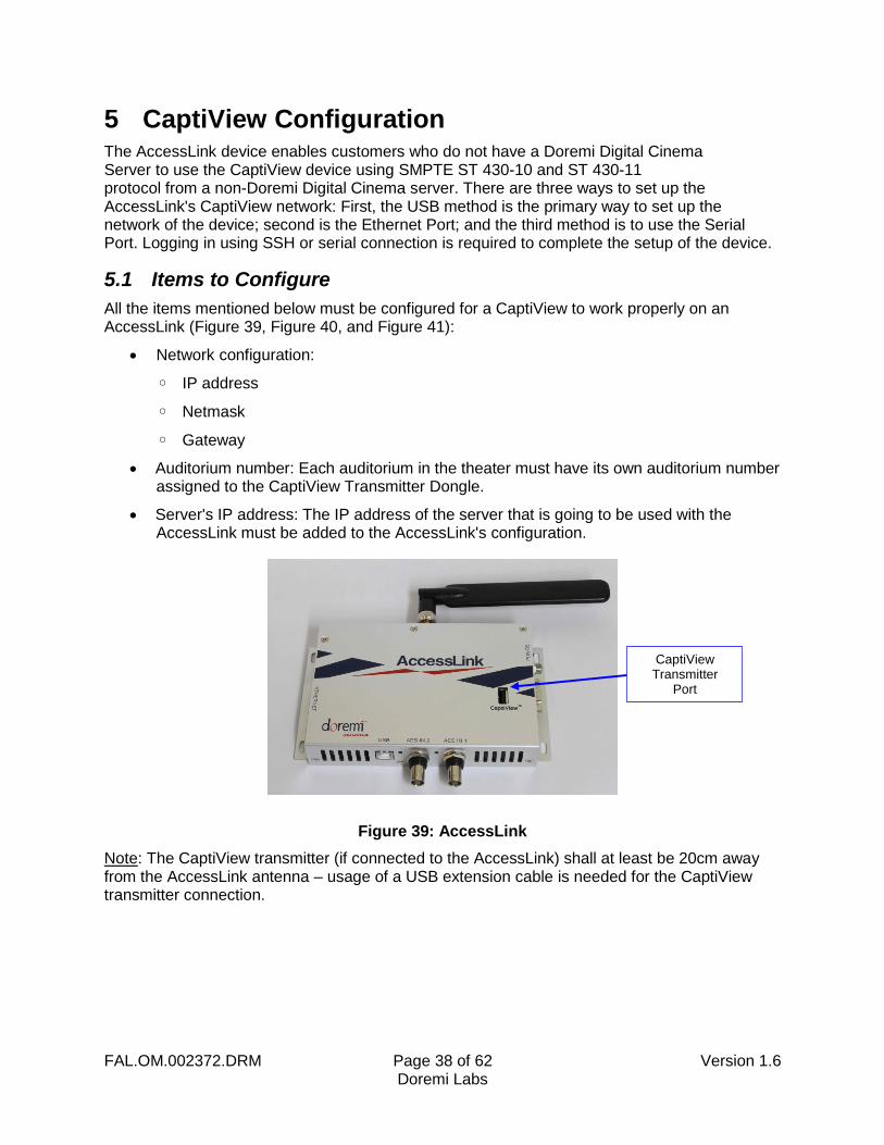
5 CaptiView Configuration The AccessLink device enables customers who do not have a Doremi Digital Cinema Server to use the CaptiView device using SMPTE ST 430-10 and ST 430-11 protocol from a non-Doremi Digital Cinema server. There are three ways to set up the AccessLink's CaptiView network: First, the USB method is the primary way to set up the network of the device; second is the Ethernet Port; and the third method is to use the Serial Port. Logging in using SSH or serial connection is required to complete the setup of the device.
5.1 Items to Configure
All the items mentioned below must be configured for a CaptiView to work properly on an AccessLink (Figure 39, Figure 40, and Figure 41):
Network configuration:
◦ IP address
◦ Netmask
◦ Gateway
Auditorium number: Each auditorium in the theater must have its own auditorium number assigned to the CaptiView Transmitter Dongle.
Server's IP address: The IP address of the server that is going to be used with the AccessLink must be added to the AccessLink's configuration.
Figure 39: AccessLink
Note: The CaptiView transmitter (if connected to the AccessLink) shall at least be 20cm away from the AccessLink antenna – usage of a USB extension cable is needed for the CaptiView transmitter connection.
CaptiView Transmitter
Port
FAL.OM.002372.DRM Page 39 of 62 Version 1.6 Doremi Labs
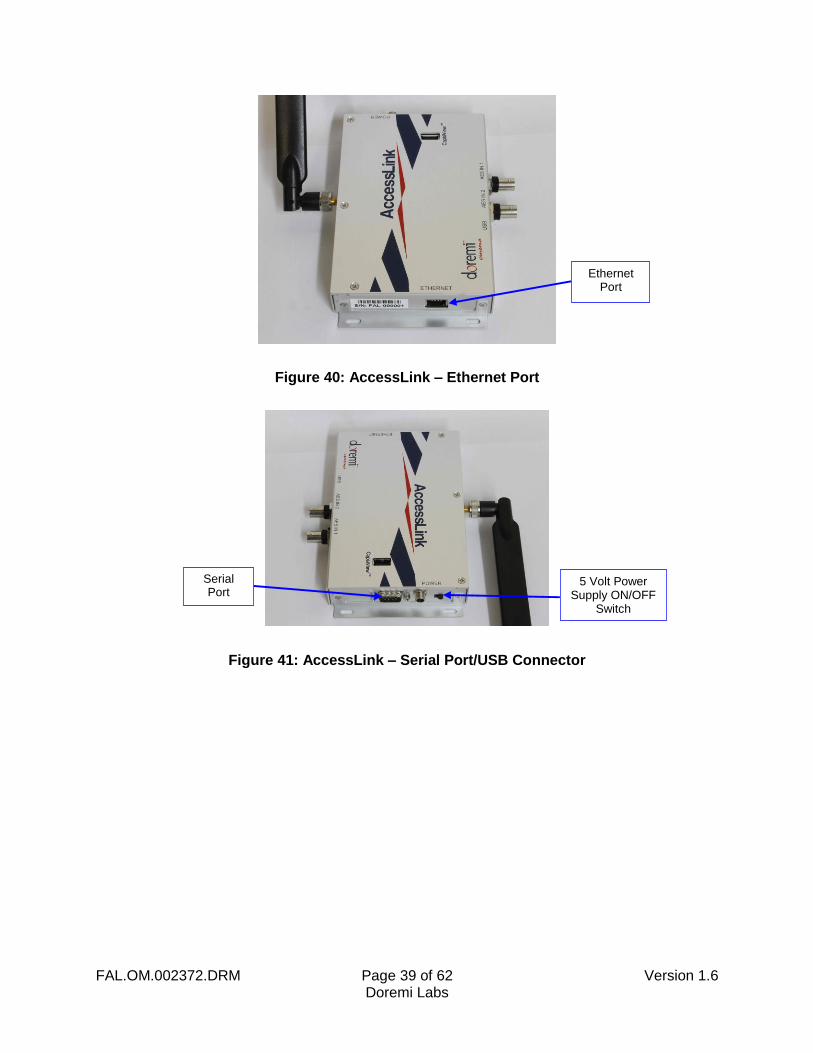
Figure 40: AccessLink – Ethernet Port
Figure 41: AccessLink – Serial Port/USB Connector
Ethernet Port
5 Volt Power Supply ON/OFF
Switch
Serial Port
FAL.OM.002372.DRM Page 40 of 62 Version 1.6 Doremi Labs
5.2 Network Configuration
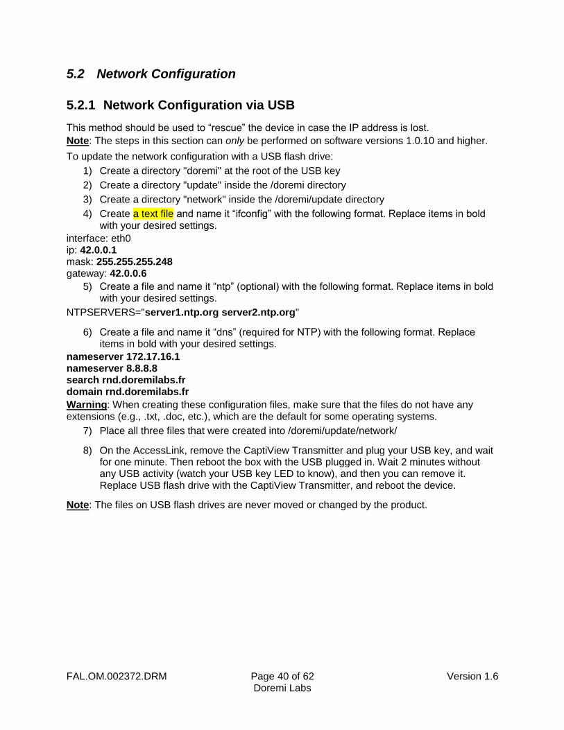
5.2.1 Network Configuration via USB
This method should be used to “rescue” the device in case the IP address is lost.
Note: The steps in this section can only be performed on software versions 1.0.10 and higher.
To update the network configuration with a USB flash drive:
1) Create a directory "doremi" at the root of the USB key
2) Create a directory "update" inside the /doremi directory
3) Create a directory "network" inside the /doremi/update directory
4) Create a text file and name it “ifconfig” with the following format. Replace items in bold with your desired settings.
interface: eth0 ip: 42.0.0.1 mask: 255.255.255.248 gateway: 42.0.0.6
5) Create a file and name it “ntp” (optional) with the following format. Replace items in bold with your desired settings.
NTPSERVERS="server1.ntp.org server2.ntp.org"
6) Create a file and name it “dns” (required for NTP) with the following format. Replace items in bold with your desired settings.
nameserver 172.17.16.1 nameserver 8.8.8.8 search rnd.doremilabs.fr domain rnd.doremilabs.fr
Warning: When creating these configuration files, make sure that the files do not have any extensions (e.g., .txt, .doc, etc.), which are the default for some operating systems.
7) Place all three files that were created into /doremi/update/network/
8) On the AccessLink, remove the CaptiView Transmitter and plug your USB key, and wait for one minute. Then reboot the box with the USB plugged in. Wait 2 minutes without any USB activity (watch your USB key LED to know), and then you can remove it. Replace USB flash drive with the CaptiView Transmitter, and reboot the device.
Note: The files on USB flash drives are never moved or changed by the product.
FAL.OM.002372.DRM Page 41 of 62 Version 1.6 Doremi Labs
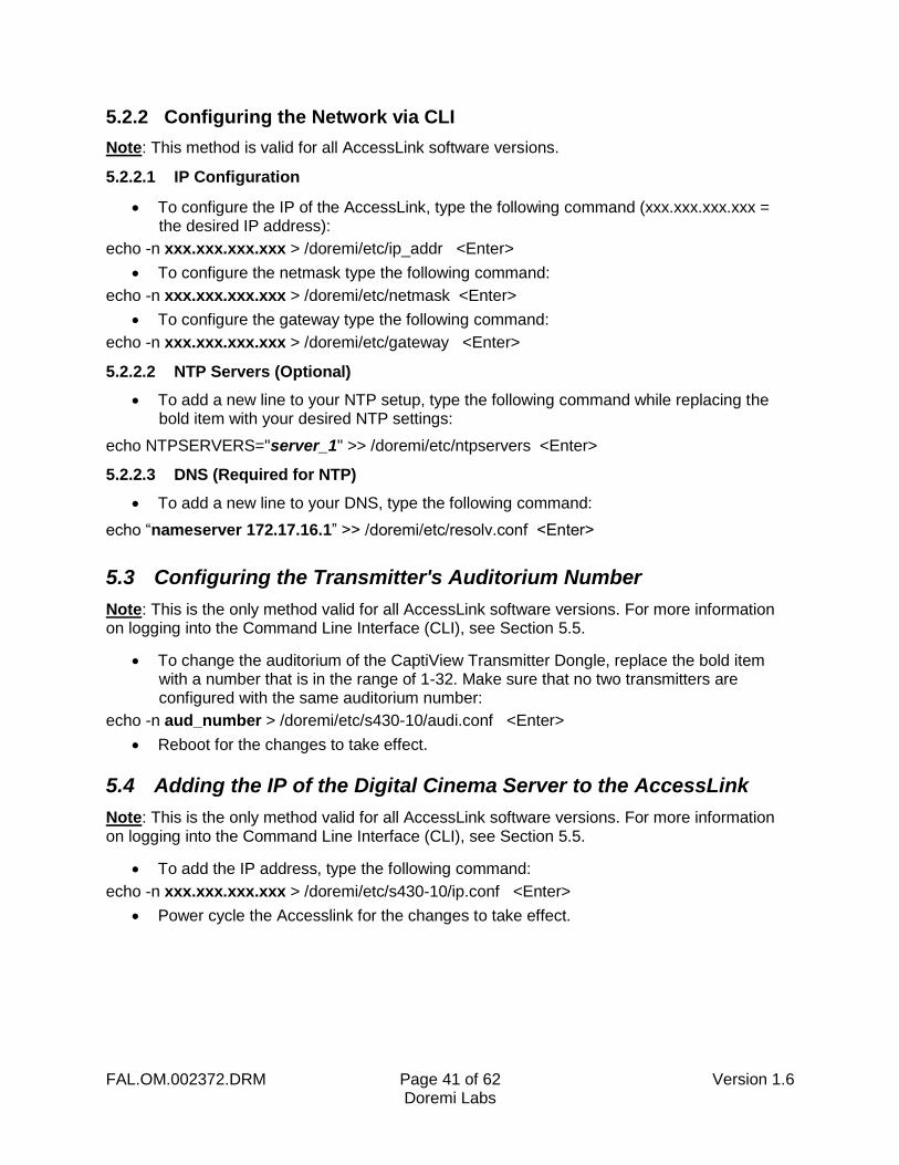
5.2.2 Configuring the Network via CLI
Note: This method is valid for all AccessLink software versions.
5.2.2.1 IP Configuration
To configure the IP of the AccessLink, type the following command (xxx.xxx.xxx.xxx = the desired IP address):
echo -n xxx.xxx.xxx.xxx > /doremi/etc/ip_addr <Enter>
To configure the netmask type the following command:
echo -n xxx.xxx.xxx.xxx > /doremi/etc/netmask <Enter>
To configure the gateway type the following command:
echo -n xxx.xxx.xxx.xxx > /doremi/etc/gateway <Enter>
5.2.2.2 NTP Servers (Optional)
To add a new line to your NTP setup, type the following command while replacing the bold item with your desired NTP settings:
echo NTPSERVERS="server_1" >> /doremi/etc/ntpservers <Enter>
5.2.2.3 DNS (Required for NTP)
To add a new line to your DNS, type the following command:
echo “nameserver 172.17.16.1” >> /doremi/etc/resolv.conf <Enter>
5.3 Configuring the Transmitter's Auditorium Number
Note: This is the only method valid for all AccessLink software versions. For more information on logging into the Command Line Interface (CLI), see Section 5.5.
To change the auditorium of the CaptiView Transmitter Dongle, replace the bold item with a number that is in the range of 1-32. Make sure that no two transmitters are configured with the same auditorium number:
echo -n aud_number > /doremi/etc/s430-10/audi.conf <Enter>
Reboot for the changes to take effect.
5.4 Adding the IP of the Digital Cinema Server to the AccessLink
Note: This is the only method valid for all AccessLink software versions. For more information on logging into the Command Line Interface (CLI), see Section 5.5.
To add the IP address, type the following command:
echo -n xxx.xxx.xxx.xxx > /doremi/etc/s430-10/ip.conf <Enter>
Power cycle the Accesslink for the changes to take effect.
FAL.OM.002372.DRM Page 42 of 62 Version 1.6 Doremi Labs
5.5 Logging into AccessLink
5.5.1 Logging into AccessLink via SSH
The default IP address of the AccessLink is 192.168.9.10.
Set your computer's IP address in the range '192.168.9.xx', xx being in the range (2-254 except 10 when using default IP).
Connect the AccessLink with an Ethernet cable to the newly configured port and power ON.
Download and install the program "PuTTY" (or any ssh client) on the computer you just assigned the new IP address to.
Connect to the default IP 192.168.9.10 on port 22 using the ssh client.
Note: If the IP address was changed using the USB method, use the IP address that was assigned to the AccessLink instead of the default IP.
When the unit is done booting up, log in as "root."
o Password for "root:" "veeone"
o It is recommended to change the "root" password by typing the following command and following the on-screen instructions: "passwd"
5.5.2 Logging into AccessLink via Serial Port
The serial cable required for a proper connection is a female-to-female, pin-to-pin cable, which should be provided in the package.
◦ Serial connection settings are:
▪ Speed 115200
▪ Data bits: 8
▪ Stop bits: 1
▪ Parity: None
▪ Flow control: None
◦ Connect and switch the device on and wait for it to boot.
When the unit is done booting up, log in as "root."
◦ Password for "root" is “veeone”
It is recommended to change the root password by doing this command and following the on-screen instructions: "passwd"
FAL.OM.002372.DRM Page 43 of 62 Version 1.6 Doremi Labs
5.6 Upgrading the AccessLink Software
There are two ways to upgrade the software on the AccessLink. One way is to use an FTP client (e.g., Core FTP or Filezilla), and the other method is to use a USB flash drive to perform the upgrade.
5.6.1 FTP Client
Make sure that an FTP client is installed on the computer.
Turn the AccessLink ON and make sure it is able to ping to the network.
Open the FTP client and connect using the IP of the AccessLink under port 21 and login as the "root" user and enter the appropriate password.
Add the update package (".pkg file") to the folder "/doremi/etc/rc.once" and then reboot.
To check if the upgrade was successful open an SSH session and type the following command: 'more /doremi/etc/version' and make sure that the version matches that of the ".pkg" file.
5.6.2 USB Flash Update
1) Create a directory name it “doremi” in the root of the USB flash drive.
2) Inside the “doremi” directory create another folder and name it "update" (e.g., '/doremi/update/').
3) Copy the ".pkg" file to the path of the USB flash drive '/doremi/update/' then safely unmount the USB flash drive.
4) Put the USB flash drive in place of the CaptiView Transmitter Dongle. Wait for the light to stop blinking and then do a reboot (or power cycle).
5) To check if the upgrade was successful, open an SSH session and type the following command (the version should match that of the ".pkg" file):
more /doremi/etc/version
FAL.OM.002372.DRM Page 44 of 62 Version 1.6 Doremi Labs
5.7 Generating a Report
To troubleshoot the product, all product information and logs are conveniently collected and stored in a file that can be sent to Doremi Technical Support for review.
5.7.1 Generating a Report via CLI
To generate the report via CLI, the operator has to log into the AccessLink with root access and execute the following command:
/doremi/sbin/report.sh <Enter>
The resulting file will be generated under /tmp directory; the operator will be able to use an FTP client to get it.
5.7.2 Generating a Report via USB
To generate a report using a USB key:
1) Create a directory "doremi" at the root of the USB key (might have been previously created).
2) Create a directory "report" inside /doremi directory.
3) On the product, remove the CaptiView Transmitter Dongle and plug in your USB key, then reboot the box.
4) Wait 2 minutes without any USB activity (watch your USB key LED to know), you can remove it and replace the dongle. Reboot the box.
The report will have been generated in the USB key folder /doremi/report

FAL.OM.002372.DRM Page 45 of 62 Version 1.6 Doremi Labs
This page has been intentionally left blank.
FAL.OM.002372.DRM Page 46 of 62 Version 1.6 Doremi Labs
6 Accessibility Track Mapping
6.1 ISDCF/Interop Specs
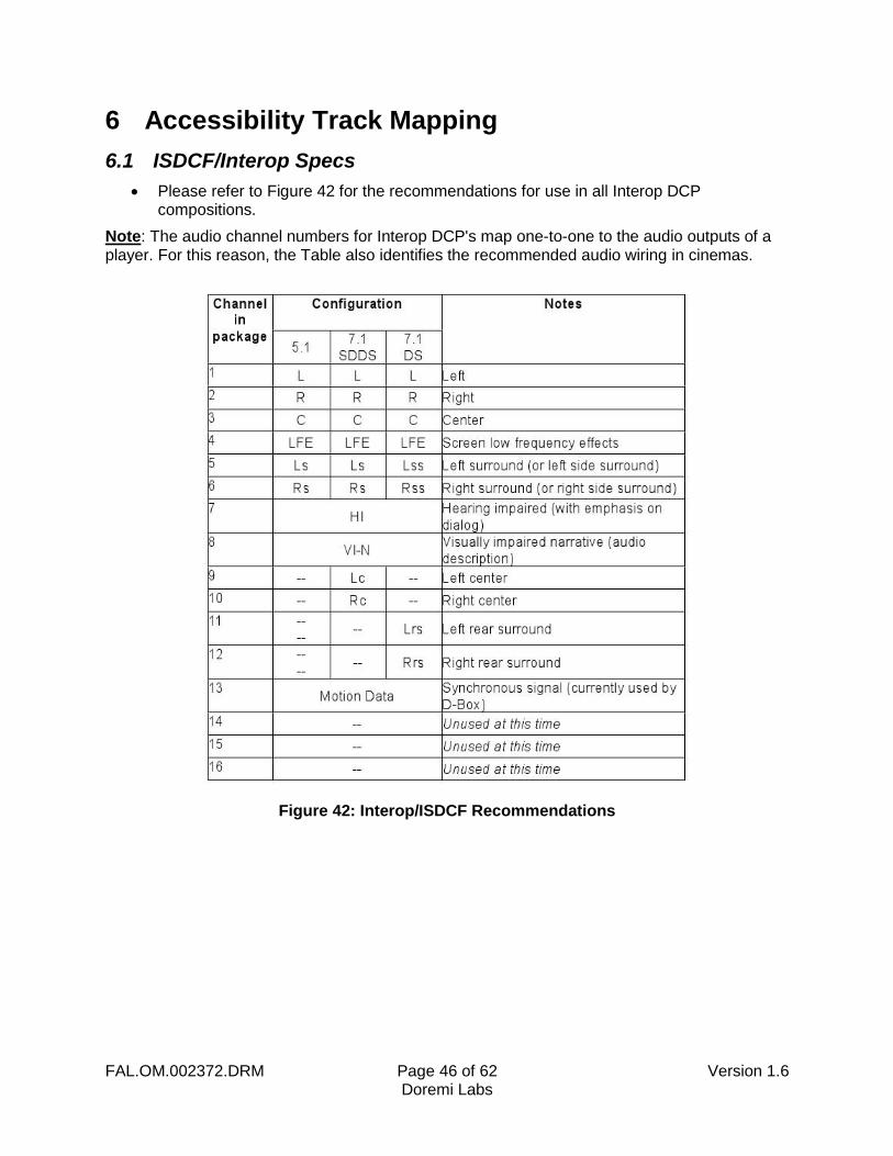
Please refer to Figure 42 for the recommendations for use in all Interop DCP compositions.
Note: The audio channel numbers for Interop DCP's map one-to-one to the audio outputs of a player. For this reason, the Table also identifies the recommended audio wiring in cinemas.
Figure 42: Interop/ISDCF Recommendations

FAL.OM.002372.DRM Page 47 of 62 Version 1.6 Doremi Labs
This page has been intentionally left blank.
FAL.OM.002372.DRM Page 48 of 62 Version 1.6 Doremi Labs
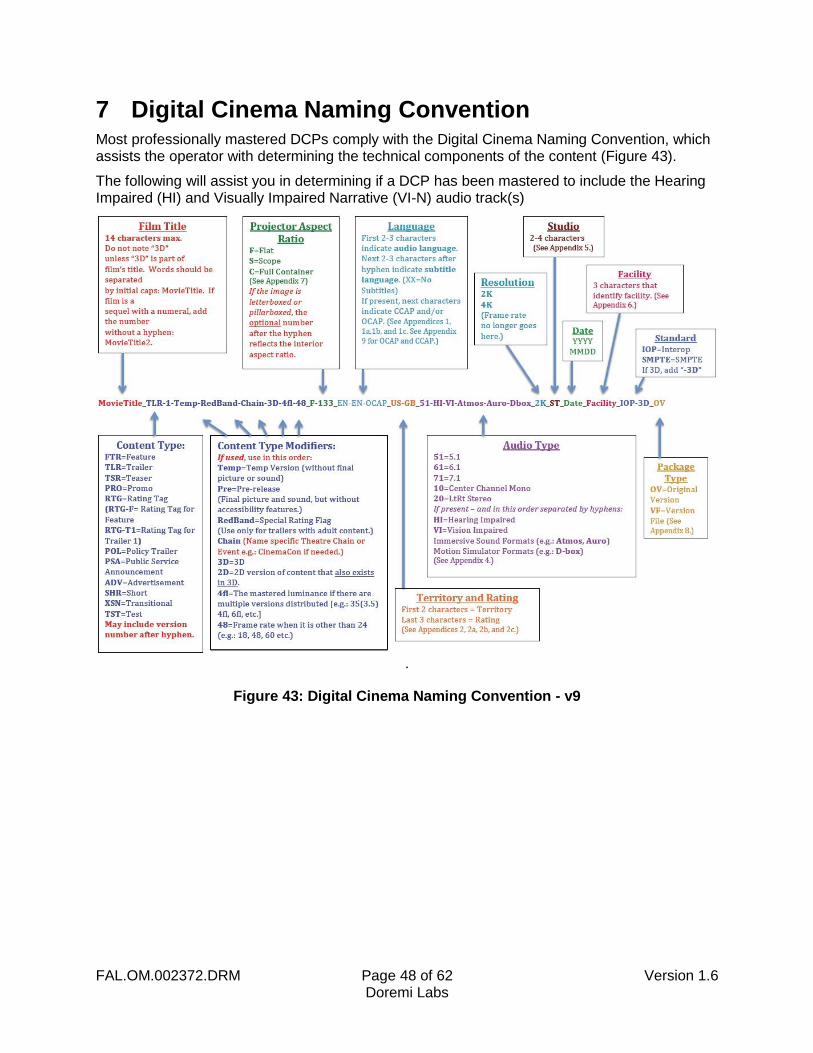
7 Digital Cinema Naming Convention Most professionally mastered DCPs comply with the Digital Cinema Naming Convention, which assists the operator with determining the technical components of the content (Figure 43).
The following will assist you in determining if a DCP has been mastered to include the Hearing Impaired (HI) and Visually Impaired Narrative (VI-N) audio track(s)
.
Figure 43: Digital Cinema Naming Convention - v9
FAL.OM.002372.DRM Page 49 of 62 Version 1.6 Doremi Labs
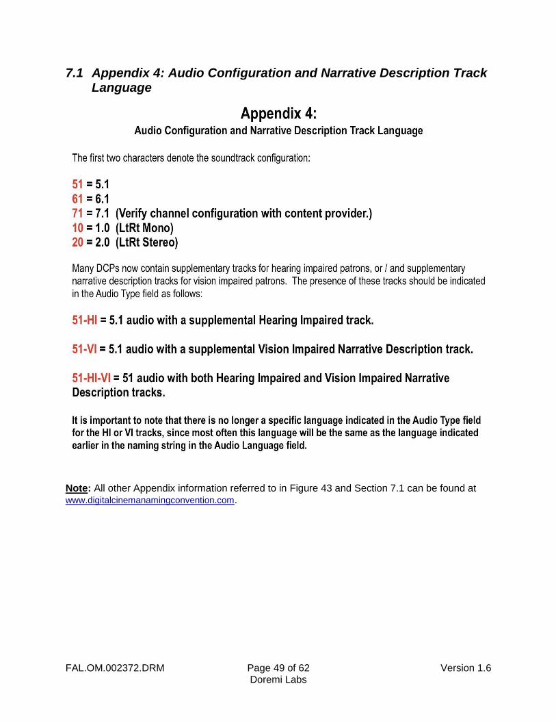
7.1 Appendix 4: Audio Configuration and Narrative Description Track Language
Note: All other Appendix information referred to in Figure 43 and Section 7.1 can be found at www.digitalcinemanamingconvention.com.

FAL.OM.002372.DRM Page 50 of 62 Version 1.6 Doremi Labs
This page has been intentionally left blank.
FAL.OM.002372.DRM Page 51 of 62 Version 1.6 Doremi Labs
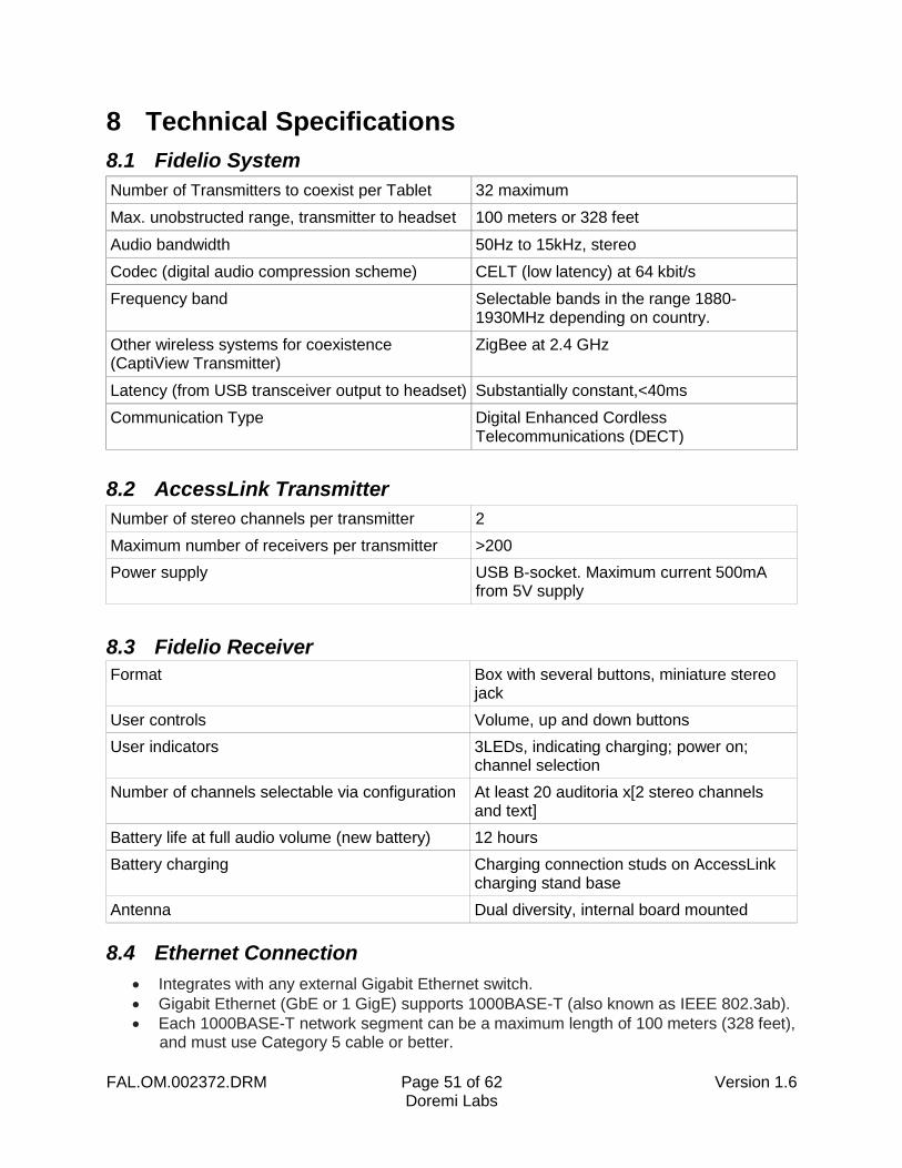
8 Technical Specifications
8.1 Fidelio System
Number of Transmitters to coexist per Tablet 32 maximum
Max. unobstructed range, transmitter to headset 100 meters or 328 feet
Audio bandwidth 50Hz to 15kHz, stereo
Codec (digital audio compression scheme) CELT (low latency) at 64 kbit/s
Frequency band Selectable bands in the range 1880-1930MHz depending on country.
Other wireless systems for coexistence (CaptiView Transmitter)
ZigBee at 2.4 GHz
Latency (from USB transceiver output to headset) Substantially constant,<40ms
Communication Type Digital Enhanced Cordless Telecommunications (DECT)
8.2 AccessLink Transmitter
Number of stereo channels per transmitter 2
Maximum number of receivers per transmitter >200
Power supply USB B-socket. Maximum current 500mA from 5V supply
8.3 Fidelio Receiver
Format Box with several buttons, miniature stereo jack
User controls Volume, up and down buttons
User indicators 3LEDs, indicating charging; power on; channel selection
Number of channels selectable via configuration At least 20 auditoria x[2 stereo channels and text]
Battery life at full audio volume (new battery) 12 hours
Battery charging Charging connection studs on AccessLink charging stand base
Antenna Dual diversity, internal board mounted
8.4 Ethernet Connection
Integrates with any external Gigabit Ethernet switch.
Gigabit Ethernet (GbE or 1 GigE) supports 1000BASE-T (also known as IEEE 802.3ab).
Each 1000BASE-T network segment can be a maximum length of 100 meters (328 feet), and must use Category 5 cable or better.

FAL.OM.002372.DRM Page 52 of 62 Version 1.6 Doremi Labs
This page has been unintentionally left blank.
FAL.OM.002372.DRM Page 53 of 62 Version 1.6 Doremi Labs
9 LED Lights Description
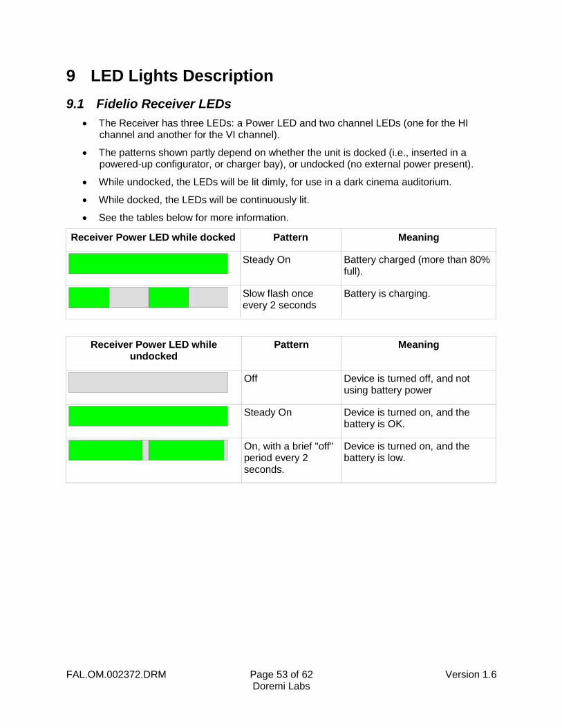
9.1 Fidelio Receiver LEDs
The Receiver has three LEDs: a Power LED and two channel LEDs (one for the HI channel and another for the VI channel).
The patterns shown partly depend on whether the unit is docked (i.e., inserted in a powered-up configurator, or charger bay), or undocked (no external power present).
While undocked, the LEDs will be lit dimly, for use in a dark cinema auditorium.
While docked, the LEDs will be continuously lit.
See the tables below for more information.
Receiver Power LED while docked Pattern Meaning
Steady On Battery charged (more than 80%
full).
Slow flash once every 2 seconds
Battery is charging.
Receiver Power LED while undocked
Pattern Meaning
Off Device is turned off, and not
using battery power
Steady On Device is turned on, and the
battery is OK.
On, with a brief "off" period every 2 seconds.
Device is turned on, and the battery is low.
FAL.OM.002372.DRM Page 54 of 62 Version 1.6 Doremi Labs
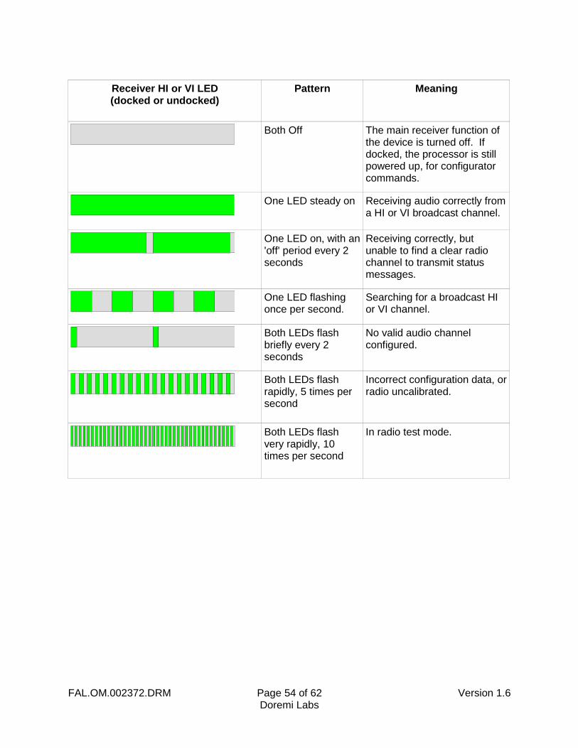
Receiver HI or VI LED (docked or undocked)
Pattern Meaning
Both Off The main receiver function of
the device is turned off. If docked, the processor is still powered up, for configurator commands.
One LED steady on Receiving audio correctly from
a HI or VI broadcast channel.
One LED on, with an 'off' period every 2 seconds
Receiving correctly, but unable to find a clear radio channel to transmit status messages.
One LED flashing once per second.
Searching for a broadcast HI or VI channel.
Both LEDs flash briefly every 2 seconds
No valid audio channel configured.
Both LEDs flash rapidly, 5 times per second
Incorrect configuration data, or radio uncalibrated.
Both LEDs flash very rapidly, 10 times per second
In radio test mode.
FAL.OM.002372.DRM Page 55 of 62 Version 1.6 Doremi Labs
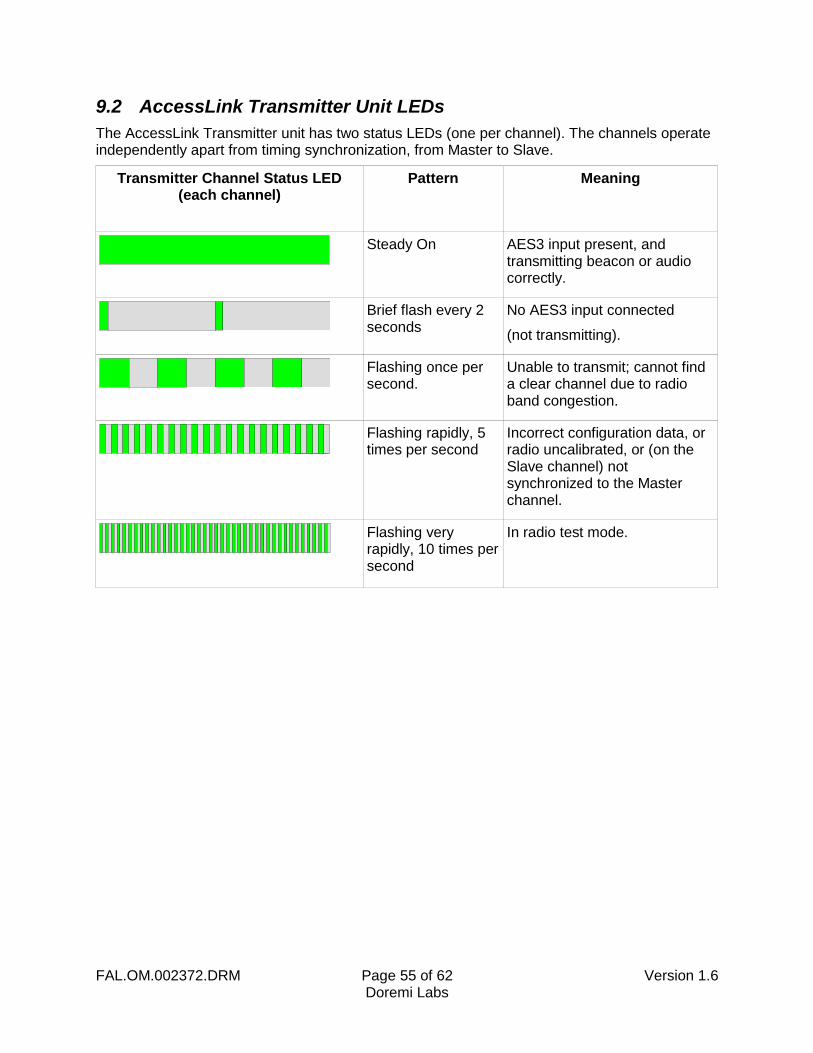
9.2 AccessLink Transmitter Unit LEDs
The AccessLink Transmitter unit has two status LEDs (one per channel). The channels operate independently apart from timing synchronization, from Master to Slave.
Transmitter Channel Status LED (each channel)
Pattern Meaning
Steady On AES3 input present, and
transmitting beacon or audio correctly.
Brief flash every 2 seconds
No AES3 input connected
(not transmitting).
Flashing once per second.
Unable to transmit; cannot find a clear channel due to radio band congestion.
Flashing rapidly, 5 times per second
Incorrect configuration data, or radio uncalibrated, or (on the Slave channel) not synchronized to the Master channel.
Flashing very rapidly, 10 times per second
In radio test mode.

FAL.OM.002372.DRM Page 56 of 62 Version 1.6 Doremi Labs
This page has been intentionally left blank.
FAL.OM.002372.DRM Page 57 of 62 Version 1.6 Doremi Labs
10 Appendix A: Wiring Guide
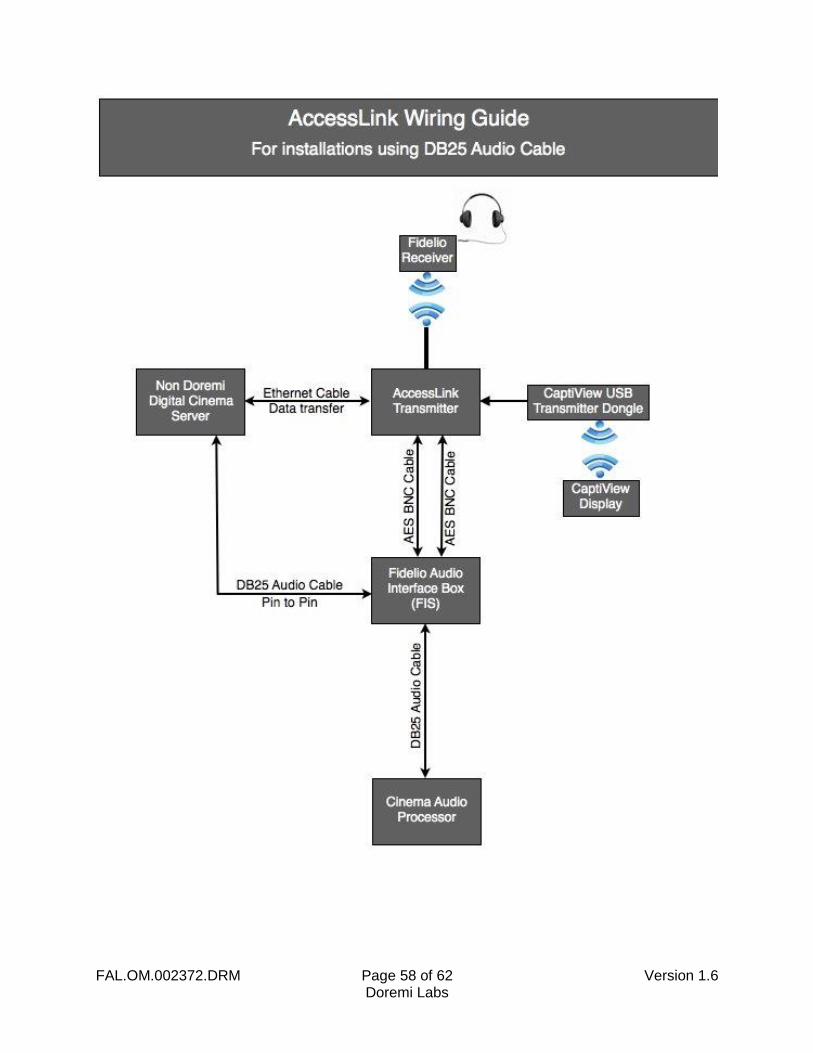
FAL.OM.002372.DRM Page 58 of 62 Version 1.6 Doremi Labs

FAL.OM.002372.DRM Page 59 of 62 Version 1.6 Doremi Labs
This page has been intentionally left blank.
FAL.OM.002372.DRM Page 60 of 62 Version 1.6 Doremi Labs
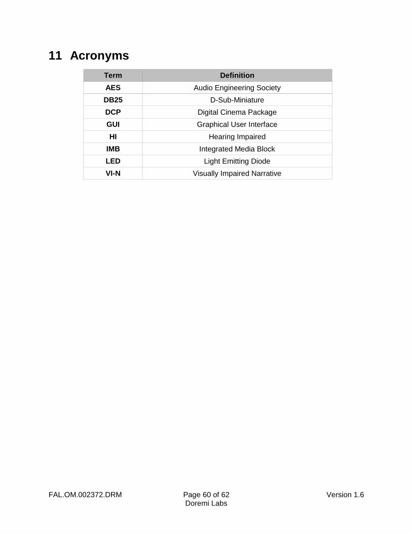
11 Acronyms
Term Definition
AES Audio Engineering Society
DB25 D-Sub-Miniature
DCP Digital Cinema Package
GUI Graphical User Interface
HI Hearing Impaired
IMB Integrated Media Block
LED Light Emitting Diode
VI-N Visually Impaired Narrative

FAL.OM.002372.DRM Page 61 of 62 Version 1.6 Doremi Labs
This page has been intentionally left blank.
FAL.OM.002372.DRM Page 62 of 62 Version 1.6 Doremi Labs
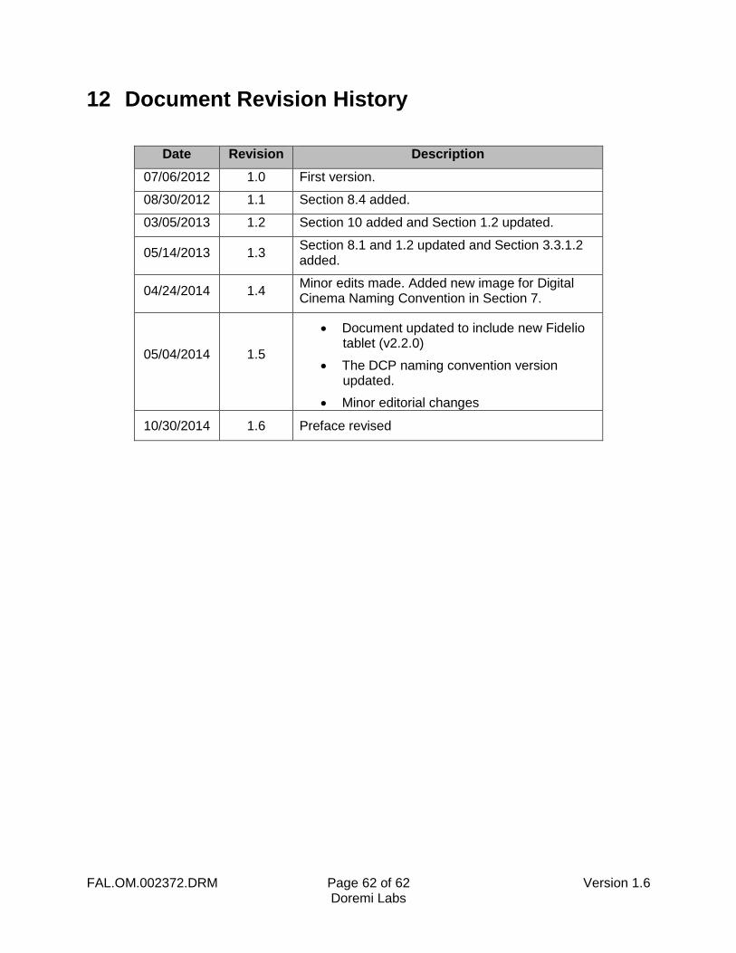
12 Document Revision History
Date Revision Description
07/06/2012 1.0 First version.
08/30/2012 1.1 Section 8.4 added.
03/05/2013 1.2 Section 10 added and Section 1.2 updated.
05/14/2013 1.3 Section 8.1 and 1.2 updated and Section 3.3.1.2 added.
04/24/2014 1.4 Minor edits made. Added new image for Digital Cinema Naming Convention in Section 7.
05/04/2014 1.5
Document updated to include new Fidelio tablet (v2.2.0)
The DCP naming convention version updated.
Minor editorial changes
10/30/2014 1.6 Preface revised