Embed Size (px)
Citation preview
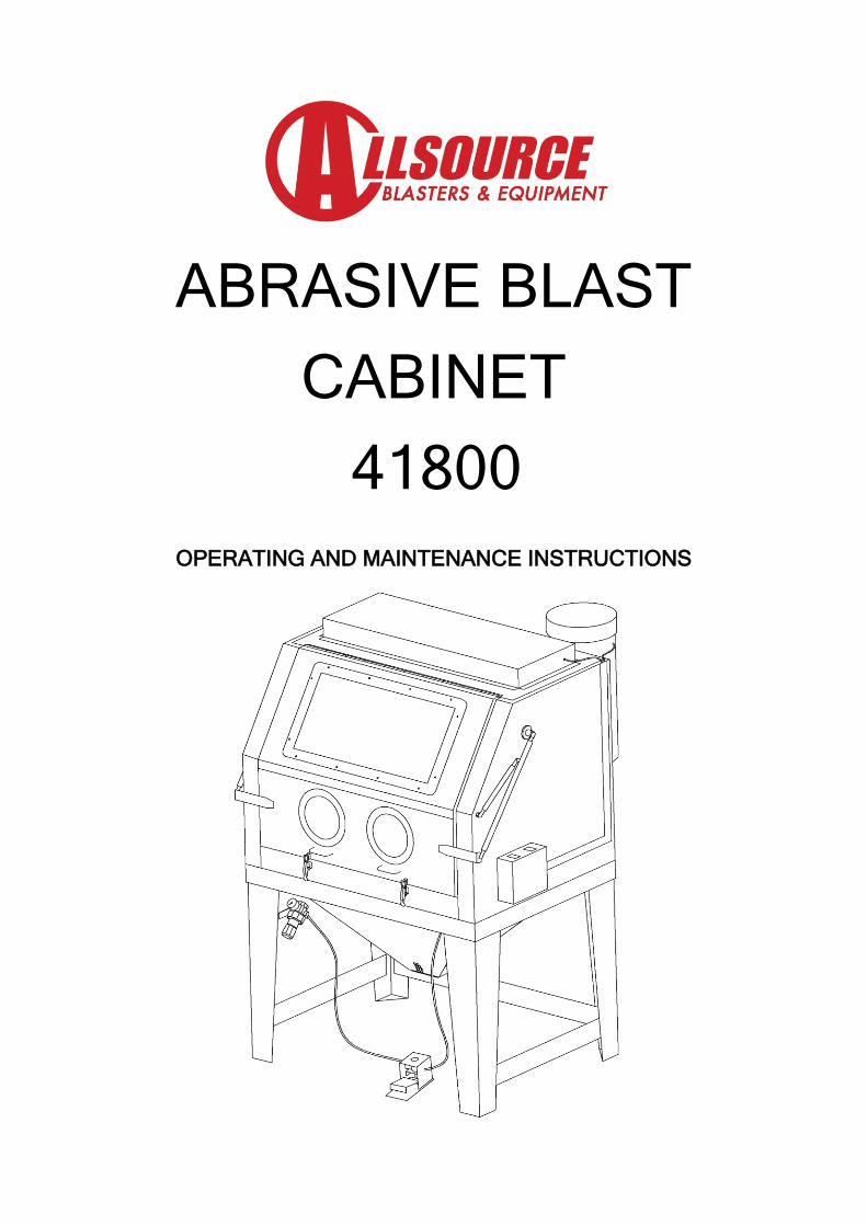
ABRASIVE BLAST
CABINET
41800
OPERATING AND MAINTENANCE INSTRUCTIONS
Page 1
CONTENTS
TECHNICAL SPECIFICATIONS Pg 1
IMPORTANT WARNINGS Pg 2-3
CABINET BLASTER SAFETY PROCEDURES Pg 4
IMPORTANT INFORMATION Pg 5
IMPORTANT NOTICES Pg 6
ASSEMBLY INSTRUCTIONS Pg 7-10
OPERATION INSTRUCTIONS Pg 10
MAINTENANCE INSTRUCTIONS Pg 10-11
MAINTAIN SUCTION EFFICIENCY WITH SIMPLE STEPS Pg 11-12
RECOMMENDATIONS Pg 13
REQUIREMENTS Pg 14
MEDIA / ABRASIVES Pg 15
CABINET PARTS DIAGRAM & PARTS LIST Pg 16-19
DISCLAIMER & LIMITED WARRANTY Pg 20
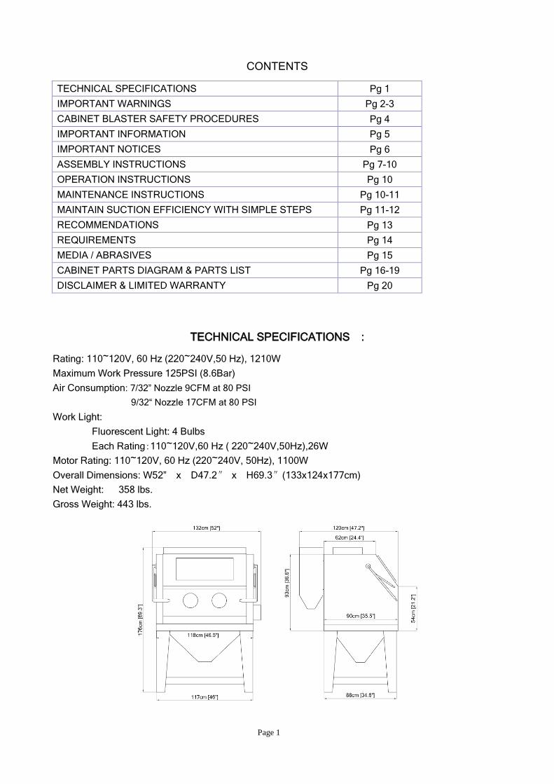
TECHNICAL SPECIFICATIONS :
Rating: 110~120V, 60 Hz (220~240V,50 Hz), 1210W
Maximum Work Pressure 125PSI (8.6Bar)
Air Consumption: 7/32” Nozzle 9CFM at 80 PSI
9/32“ Nozzle 17CFM at 80 PSI
Work Light:
Fluorescent Light: 4 Bulbs
Each Rating:110~120V,60 Hz ( 220~240V,50Hz),26W
Motor Rating: 110~120V, 60 Hz (220~240V, 50Hz), 1100W
Overall Dimensions: W52” x D47.2″ x H69.3″(133x124x177cm)
Net Weight: 358 lbs.
Gross Weight: 443 lbs.
Page 2
WARNING!
Do not use a Cabinet Blaster until you have read this manual and you understand its contents and
warnings. These warnings are included for the health and safety of the operator and those in the
immediate vicinity. Keep this manual for future reference.
Dust created by power sanding, sawing, grinding, drilling, and other construction activities may
contain chemicals known to cause cancer, birth defects or other reproductive harm and respiratory
illnesses. Some examples of the chemicals include:
- Lead from lead based paints
- Crystalline silica from bricks, cement and other masonry products
- Arsenic and chromium from chemically-treated lumber
Your risk from these exposures varies, depending on how often you do this type of work. To reduce
your exposure to these chemicals: Work in a ventilated area, and work with approved safety
equipment specially designed to filter out microscopic particles.
Abrasive blasting produces harmful dust. Everyone in the blasting area must wear a properly fitted
and properly maintained NIOSH approved air supplied respirator.
SILICOSIS AND OTHER DUST WARNINGS:
Breathing dust from silica sand may cause silicosis, a fatal lung disease. Breathing dust during
blasting operations may also cause asbestosis and/or other serious or fatal diseases. A
NIOSH-approved, well maintained air supplied abrasive blasting respirator must be used by anyone
blasting, anyone handling or using media containing toxic substances or media with more than one
percent free crystalline silica and anyone in the area of the dust. Harmful dust can remain
suspended in the air for long periods of time after blasting has ceased, causing serious injury or
death.
Before removing respirator, use an air monitoring instrument to determine if atmosphere is safe to
breathe. Contact local OSHA or NIOSH office to determine the proper respirator for your particular
application.
Air supplied respirators do not remove or protect against carbon monoxide (CO) or any other toxic
gas. Use a carbon monoxide removal device and monitoring device with the respirator to ensure
grade D quality air. Follow all applicable OSHA standards and OSHA regulation 1910.134 (d).
Do not use this equipment in any area that might be considered hazardous or where flammable
gases or liquids are present. Failure to do so may cause an explosion resulting in serious injury.
Page 3
WARNING AND SAFETY INFORMATION
Do not operate cabinet or air flow with cabinet door
Open or with cabinet lens removed.
Do not use fluids or mix fluids with blast media.
This cabinet is designed for dry blasting only.
Do not exceed maximum operating pressure of 125 PSI.
WARNING!
Disconnecting hose while Unit is under pressure could cause serious injury or death. Use safety
lock pins and safety cables in all coupling connections to help prevent hose couplings from
accidental disconnection.
WARNING!
Failure to observe the following before performing any maintenance could cause serious injury or
death from the sudden release of compressed air:
- Disconnect power supply
- Lockout and tagout the compressed air supply
- Bleed the air supply line to the blast gun.
Immediate replacement of worn components is required. Failure to replace worn components could
expose the operator or bystanders to high speed media and compressed air could cause death or
serious injury.
Leaks around couplings and nozzle holders indicate worn or loose fitting parts. Nozzle holders and
couplings that do not fit tightly on hose and nozzles that do not fit tightly in nozzle holders could
disconnect while under pressure. Impact from nozzles, couplings, hoses, or abrasive, and parts
disconnected while under pressure could cause severe injury.
The threads on the nozzle holder must be inspected each time the nozzle is secured to the holder.
Check the threads for wear, and make sure nozzle screw securely grips the nozzle. The nozzle
washer must also be inspected for wear. Worn nozzle washers cause erosion. A loose-fitting nozzle
may eject from the holder under pressure and could cause severe injury.
Page 4
CABINET BLASTER SAFETY PROCEDURES
CAUTION: READ THESE SAFETY PROCEDURES IN THEIR ENTIRETY -
PARTS OF THE OPERATING INSTRUCTIONS ARE WITHIN THESE WARNINGS.
These procedures are not intended to be exhaustive due to the many variables in the abrasive
blasting field. Therefore, we INSIST that the hands, ears, mouth, nose and eyes be covered with
appropriate safety protection at all times.
ADDITIONAL WARNINGS!
CAUTION MUST BE EXERCISED BY USER AT ALL TIMES
1. Do not exceed maximum working pressure of 125 PSI. Failure to keep maximum working
pressure below 125 PSI can cause the blast machine to burst, causing death or serious
injury.
2. Everyone in the blast area including the equipment operator should correctly use and
maintain a NIOSH approved air supplied respirator, even after blasting has ceased. Harmful
dust can remain suspended in the air for long periods of time after blasting has ceased
causing injury or death.
3. For safe operation, perform recommended preventive maintenance on blaster cabinet, and
accessories. Replace all worn parts before they fail. Immediate replacement of worn
components is required. Failure to replace worn components could result in exposing the
operator or bystanders to high speed media and compressed air, causing serious injury.
4. Do not use corrosive materials of any type in unit. Use only clean, dry media.
5. Static electricity can be created by the use of this equipment. Don not use within fifty feet of
any explosive, potentially explosive substances, or their vapors as an explosion can occur.
Page 5
IMPORTANT INFORMATION
Read all instructions before using this equipment. Save these instructions for future reference.
Remember:
1. Start up preparations:
Supply air line should be sized appropriately. See page 14. All hoses should be rated at
least 125 PSI and an isolation valve should be installed so that supply air can be turned off
and then disconnected from blast machine for servicing.
Supply air should be dry and clean from oil and other contaminants. (i.e. use air dryer,
coalescent filter, or moisture separator as needed.)
Blast machine must be grounded to avoid shock.
Electric extension cords should be three wire grounded, and rated for the amperage of the
blaster. Check nameplate for rated amps.
2. Operator’s responsibilities before starting:
Inspect fittings and hoses for damage and wear.
Check the seal on all doors. Only operate the blast cabinet with all doors securely closed
and dust collection system running.
Clean dust from dust collector and clean filter as needed.
3. Caution:
Unless otherwise specified, working pressure of blast machine and related components
must not exceed 125 PSI.
Keep blast nozzle controlled and aimed at the work.
4. Maintenance:
Keep your machine in good repair. Use ALLSOURCE parts and do not substitute or modify
ALLSOURCE supplied items.
Page 6
IMPORTANT NOTICE
TO DISTRIBUTORS, PURHCASERS AND END USERS OF ALLSOURCE PRODUCTS
The information provided described and illustrated in this material is intended for experienced,
knowledgeable users of abrasive blasting equipment and supplies (products).
The products described in this material may be combined as determined solely by the user in a variety of
way and purposes. However no representations are made as to intended use, performance standards,
engineering suitability, safe practices or compliance with government regulation and laws that apply to
these products, products of others, or a combination of various products of third parties, and a
combination of various products chosen by the user or others. It is the responsibility of the users of these
products, products of third parties, and a combination of various products, to exercise caution and
familiarize themselves with all applicable laws, government regulations and safety requirements.
Nor are representations made or intended as to the useful life, maintenance cycles, efficiency or
performance of the referenced products or any combination of products.
This material must not be used for estimating purpose. Production rates, labor performance or surface
finishes are the sole responsibility of the user based on the user’s expertise, experience and knowledge
of industry variables.
It is the responsibility of the user to insure that proper and comprehensive training of operators has been
performed and all environmental and safety precautions observed.
ALLSOURCE provides a variety of excellent products to the surface preparation industry, and we are
confident that all proficient users, operators and contractors in this industry will continue to use our
products in a safe and knowledge manner.
Before using this product, read all instructions, literature, labels, specifications and warnings sent with
and affixed to the unit. If operation of the unit is unclear after reading this manual, contact your
supervisor for instructions. It is the responsibility of the employer to read the following instructions to
users of this equipment, who are unable to read. Periodic inspection at the work site should be made
by supervisory personnel to ensure the blast machine is being properly used and maintained. A copy of
this owner’s manual must be kept with the blast machine and readily accessible to the blast machine
operators at all times.
Page 7
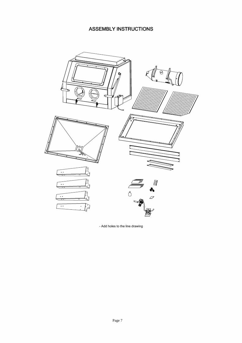
ASSEMBLY INSTRUCTIONS
- Add holes to the line drawing
Page 8
- add holes to line drawing
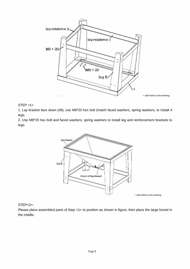
STEP <1>
1. Lay bracket face down (#8), use M8*20 hex bolt (match faced washers, spring washers, to install 4
legs.
2. Use M8*20 hex bolt and faced washers, spring washers to install leg and reinforcement brackets to
legs.
- add holes to line drawing
STEP<2>:
Please place assembled parts of Step <1> to position as shown in figure, then place the large funnel in
the middle.
Page 9
- add holes to line drawing
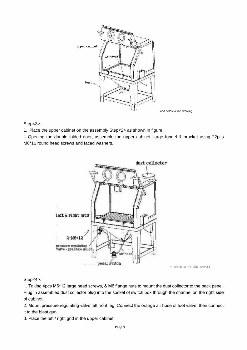
Step<3>:
1. Place the upper cabinet on the assembly Step<2> as shown in figure.
2.Opening the double folded door, assemble the upper cabinet, large funnel & bracket using 22pcs
M6*16 round head screws and faced washers.
- add holes to line drawing
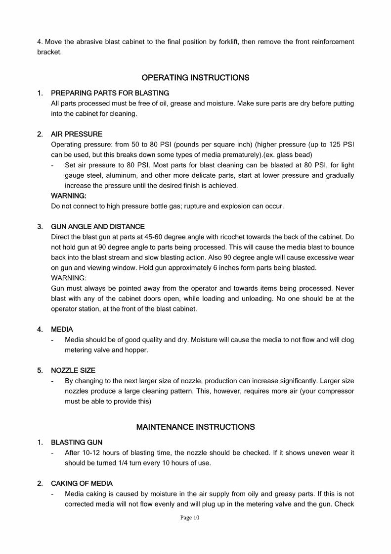
Step<4>:
1. Taking 4pcs M6*12 large head screws, & M6 flange nuts to mount the dust collector to the back panel.
Plug in assembled dust collector plug into the socket of switch box through the channel on the right side
of cabinet.
2. Mount pressure regulating valve left front leg. Connect the orange air hose of foot valve, then connect
it to the blast gun.
3. Place the left / right grid in the upper cabinet.
Page 10
4. Move the abrasive blast cabinet to the final position by forklift, then remove the front reinforcement
bracket.
OPERATING INSTRUCTIONS
1. PREPARING PARTS FOR BLASTING
All parts processed must be free of oil, grease and moisture. Make sure parts are dry before putting
into the cabinet for cleaning.
2. AIR PRESSURE
Operating pressure: from 50 to 80 PSI (pounds per square inch) (higher pressure (up to 125 PSI
can be used, but this breaks down some types of media prematurely).(ex. glass bead)
- Set air pressure to 80 PSI. Most parts for blast cleaning can be blasted at 80 PSI, for light
gauge steel, aluminum, and other more delicate parts, start at lower pressure and gradually
increase the pressure until the desired finish is achieved.
WARNING:
Do not connect to high pressure bottle gas; rupture and explosion can occur.
3. GUN ANGLE AND DISTANCE
Direct the blast gun at parts at 45-60 degree angle with ricochet towards the back of the cabinet. Do
not hold gun at 90 degree angle to parts being processed. This will cause the media blast to bounce
back into the blast stream and slow blasting action. Also 90 degree angle will cause excessive wear
on gun and viewing window. Hold gun approximately 6 inches form parts being blasted.
WARNING:
Gun must always be pointed away from the operator and towards items being processed. Never
blast with any of the cabinet doors open, while loading and unloading. No one should be at the
operator station, at the front of the blast cabinet.
4. MEDIA
- Media should be of good quality and dry. Moisture will cause the media to not flow and will clog
metering valve and hopper.
5. NOZZLE SIZE
- By changing to the next larger size of nozzle, production can increase significantly. Larger size
nozzles produce a large cleaning pattern. This, however, requires more air (your compressor
must be able to provide this)
MAINTENANCE INSTRUCTIONS
1. BLASTING GUN
- After 10-12 hours of blasting time, the nozzle should be checked. If it shows uneven wear it
should be turned 1/4 turn every 10 hours of use.
2. CAKING OF MEDIA
- Media caking is caused by moisture in the air supply from oily and greasy parts. If this is not
corrected media will not flow evenly and will plug up in the metering valve and the gun. Check
Page 11
air supply; if water is present install a good moisture trap. If oily or greasy parts are being
blasted, you should degrease and dry the parts first.
3. REVERSE PRESSURE
- If media stops flowing occasionally, place cover over nozzle (hold tight) and push foot pedal
down for a couple of seconds. This will cause the system to back blast through the gun and up
the media hose. This will help loosen any clogs.
4. GUN AIR PRESSURE DROP
- Set the air pressure to 80 PSI on the air gauge at regulator. Push the foot pedal while holding
gun and see if the gauge pressure drops significantly. If the pressure drops, this indicates that
there is a restriction in the supply line. This could be that hose is too small, a reducer of quick
coupler, a plugged filter, or other piping that doesn’t allow enough air through. Also if the
cabinet is too far from the air compressor, a pressure drop will occur. Air supply line should be
½” or larger.
5. POOR VISIBILITY-EXCESSIVE DUST
- Air inlet at front left above regulator, should be free to allow air into cabinet.
- Dust container full and needs to be cleaned and emptied. (latch at bottom of dust collector)
Dust cartridge contaminated. (clean or replace filter in dust collector, part#19)
- Media breakdown; eventually the media becomes so small that it is essentially dust. Replace
media and clean dust collector.
6. POOR VISIBILITY-VIEWING WINDOW
- Viewing windows come with a clear plastic protector on them. As these become pitted they can
be easily replaced to extend the life of the window. The window can also be easily replaced
7. POOR MEDIA FLOW
- Check for moisture as indicated above. Install moisture trap as needed, replace damp media
and clean hoses and pump.
- Holes in media hose will cause poor media delivery. Replace hose.
- Debris in media. Replace or screen media.
MAINTAIN SUCTION EFFICIENCY WITH SIMPLE STEPS
The most common problem customers have with their suction (venture) blast cabinets is a decrease in
production rates. A properly maintained suction cabinet should provide years of constant service. When
production rates fall the operator can usually locate the problem by checking
1. AIR SUPPLY
- If the pressure gauge on the regulator shows an adequate no-load supply (when the blaster is
not running), press the foot pedal. If the pressure drops more than a few PSI your air supply is
restricted or inadequate. Clean filters and moisture separators all the way back to the air
compressor. Straighten any kinky lines. Use a master gauge to check the air pressure or
replace existing gauge if you suspect it is giving you false readings.
Page 12
2. BLAST GUN
- The nozzle will wear out eventually. Replace it if it's measured 1/16” over its original size or if it
shows uneven wear. Adjust as needed for different media and conditions. A properly working
gun will pull 13-17 inches of vacuum.
3. DUST COLLECTOR
- Inadequate cabinet ventilation results in reduced cleaning power at the nozzle as well as
diminished view of the work in progress. Use the dust collector, shake every 20-30 minutes
when the cabinet is turned off, (more often in dusty conditions.) Empty dust collector at least
once a day. Remove filter and blow out occasionally to keep the dust collector or vacuum
working efficiently. Replace as needed.
4. MEDIA
- Use quality blast media sized to the job. Damp to dirty media can bring blasting to an instant
halt. Store media in a dry area and load the appropriate quantity. Add enough media through
the flooring to have 6” deep of media on top of the metering valve. If you run out of media as
you are blasting add enough so it keeps circulating to the gun. The media will eventually
breakdown or get too contaminated to use. The less there is in the system, the less you will
have to replace.
5. MEDIA DELIVERY
- Replace any media hose that has soft spots or visible wear. Adjust the metering valve to
provide adequate flow. A mixture that is too rich will cause pulsating at the gun. An unusually
loud noise while blasting means the mixture is too lean. A rich mixture can result in lower
impact velocities. While a lean mixture reduces the number of impacts. Both reduce your
cleaning rate.
If everything is adjusted right and you are still not getting the production levels needed, contact
your distributor.
Page 13
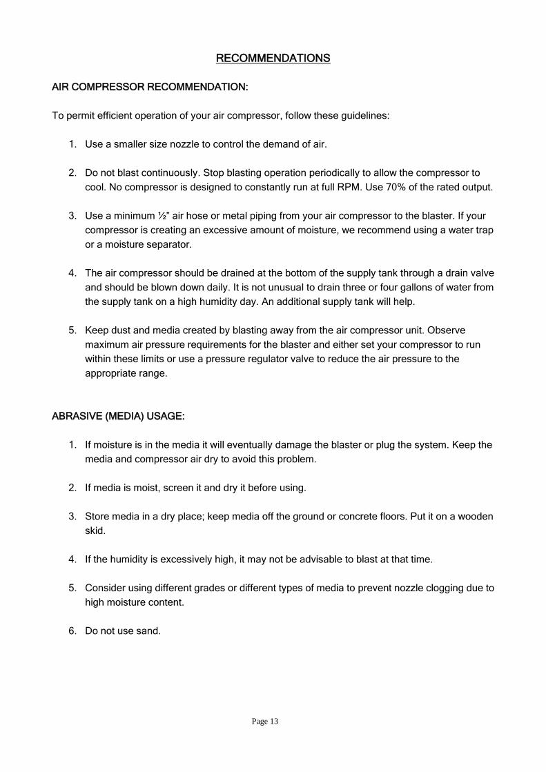
RECOMMENDATIONS
AIR COMPRESSOR RECOMMENDATION:
To permit efficient operation of your air compressor, follow these guidelines:
1. Use a smaller size nozzle to control the demand of air.
2. Do not blast continuously. Stop blasting operation periodically to allow the compressor to
cool. No compressor is designed to constantly run at full RPM. Use 70% of the rated output.
3. Use a minimum ½” air hose or metal piping from your air compressor to the blaster. If your
compressor is creating an excessive amount of moisture, we recommend using a water trap
or a moisture separator.
4. The air compressor should be drained at the bottom of the supply tank through a drain valve
and should be blown down daily. It is not unusual to drain three or four gallons of water from
the supply tank on a high humidity day. An additional supply tank will help.
5. Keep dust and media created by blasting away from the air compressor unit. Observe
maximum air pressure requirements for the blaster and either set your compressor to run
within these limits or use a pressure regulator valve to reduce the air pressure to the
appropriate range.
ABRASIVE (MEDIA) USAGE:
1. If moisture is in the media it will eventually damage the blaster or plug the system. Keep the
media and compressor air dry to avoid this problem.
2. If media is moist, screen it and dry it before using.
3. Store media in a dry place; keep media off the ground or concrete floors. Put it on a wooden
skid.
4. If the humidity is excessively high, it may not be advisable to blast at that time.
5. Consider using different grades or different types of media to prevent nozzle clogging due to
high moisture content.
6. Do not use sand.
Page 14
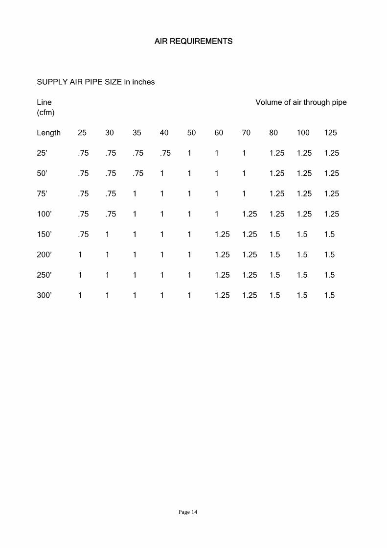
AIR REQUIREMENTS
SUPPLY AIR PIPE SIZE in inches
Line Volume of air through pipe
(cfm)
Length 25 30 35 40 50 60 70 80 100 125
25’ .75 .75 .75 .75 1 1 1 1.25 1.25 1.25
50’ .75 .75 .75 1 1 1 1 1.25 1.25 1.25
75’ .75 .75 1 1 1 1 1 1.25 1.25 1.25
100’ .75 .75 1 1 1 1 1.25 1.25 1.25 1.25
150’ .75 1 1 1 1 1.25 1.25 1.5 1.5 1.5
200’ 1 1 1 1 1 1.25 1.25 1.5 1.5 1.5
250’ 1 1 1 1 1 1.25 1.25 1.5 1.5 1.5
300’ 1 1 1 1 1 1.25 1.25 1.5 1.5 1.5
Page 15
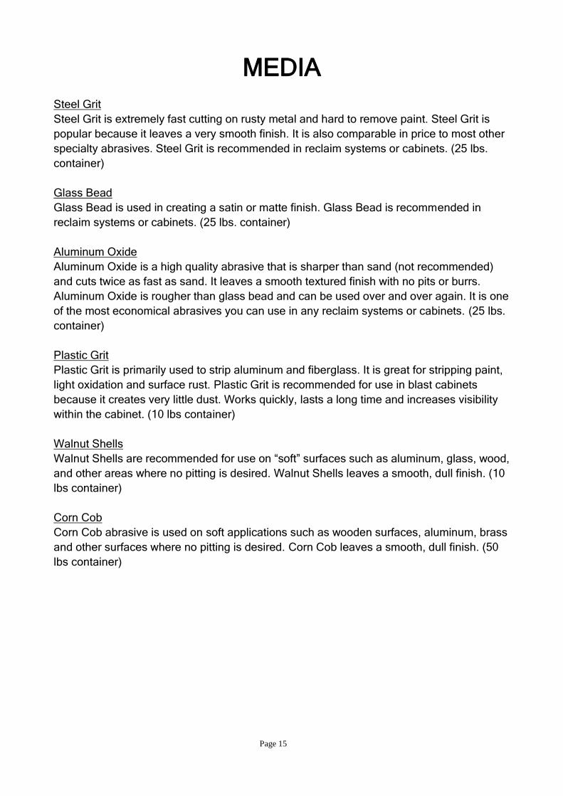
MEDIA
Steel Grit
Steel Grit is extremely fast cutting on rusty metal and hard to remove paint. Steel Grit is
popular because it leaves a very smooth finish. It is also comparable in price to most other
specialty abrasives. Steel Grit is recommended in reclaim systems or cabinets. (25 lbs.
container)
Glass Bead
Glass Bead is used in creating a satin or matte finish. Glass Bead is recommended in
reclaim systems or cabinets. (25 lbs. container)
Aluminum Oxide
Aluminum Oxide is a high quality abrasive that is sharper than sand (not recommended)
and cuts twice as fast as sand. It leaves a smooth textured finish with no pits or burrs.
Aluminum Oxide is rougher than glass bead and can be used over and over again. It is one
of the most economical abrasives you can use in any reclaim systems or cabinets. (25 lbs.
container)
Plastic Grit
Plastic Grit is primarily used to strip aluminum and fiberglass. It is great for stripping paint,
light oxidation and surface rust. Plastic Grit is recommended for use in blast cabinets
because it creates very little dust. Works quickly, lasts a long time and increases visibility
within the cabinet. (10 lbs container)
Walnut Shells
Walnut Shells are recommended for use on “soft” surfaces such as aluminum, glass, wood,
and other areas where no pitting is desired. Walnut Shells leaves a smooth, dull finish. (10
lbs container)
Corn Cob
Corn Cob abrasive is used on soft applications such as wooden surfaces, aluminum, brass
and other surfaces where no pitting is desired. Corn Cob leaves a smooth, dull finish. (50
lbs container)
Page 16
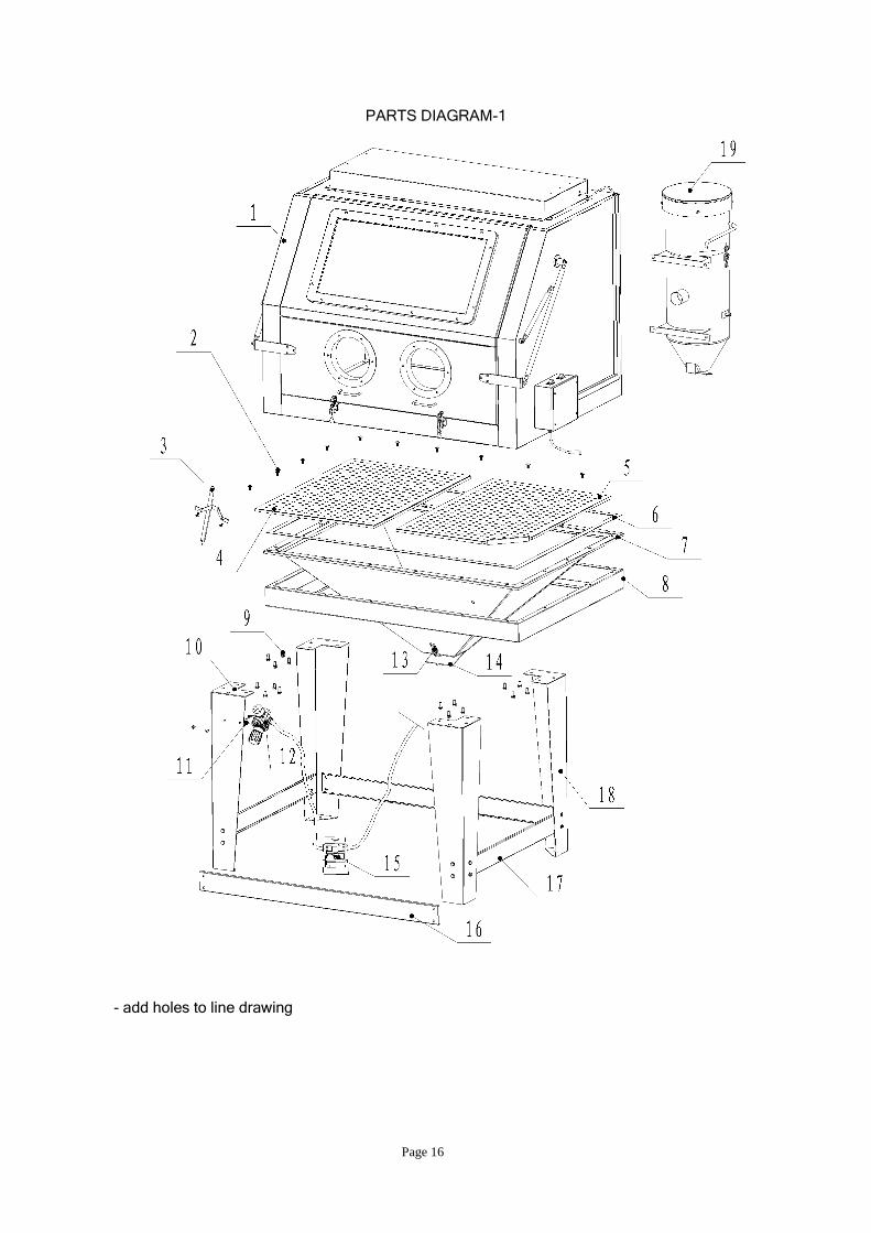
PARTS DIAGRAM-1
- add holes to line drawing
Page 17
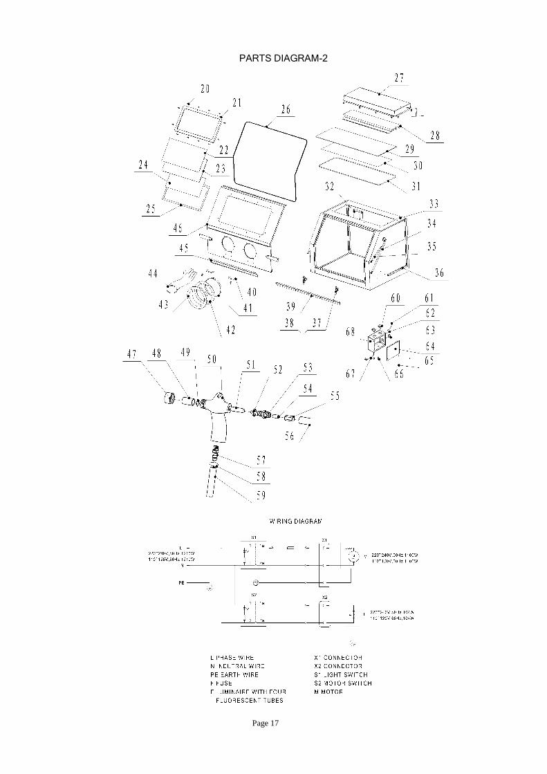
PARTS DIAGRAM-2
Page 18
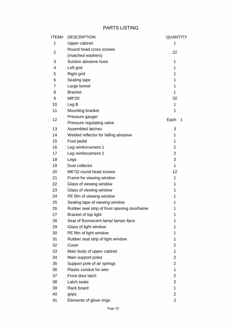
PARTS LISTING
ITEM# DESCRIPTION QUANTITY
1 Upper cabinet 1
2 Round head cross screws
(matched washers) 22
3 Suction abrasive hose 1
4 Left grid 1
5 Right grid 1
6 Sealing tape 1
7 Large funnel 1
8 Bracket 1
9 M8*20 32
10 Leg B 1
11 Mounting bracket 1
12 Pressure gauge/
Pressure regulating valve Each 1
13 Assembled latches 3
14 Welded reflector for falling abrasive 1
15 Foot pedal 1
16 Leg reinforcement 1 2
17 Leg reinforcement 2 2
18 Legs 3
19 Dust collector 1
20 M6*32 round head screws 12
21 Frame for viewing window 1
22 Glass of viewing window 1
23 Glass of viewing window 1
24 PE film of viewing window 1
25 Sealing tape of viewing window 1
26 Rubber seal strip of front opening doorframe 1
27 Bracket of top light 1
28 Seat of fluorescent lamp/ lamps 4pcs 1
29 Glass of light window 1
30 PE film of light window 1
31 Rubber seal strip of light window 1
32 Cover 2
33 Main body of upper cabinet 1
34 Main support poles 2
35 Support pole of air springs 2
36 Plastic conduit for wire 1
37 Front door latch 2
38 Latch seats 2
39 Rack board 1
40 grips 2
41 Elements of glove rings 2
Page 19
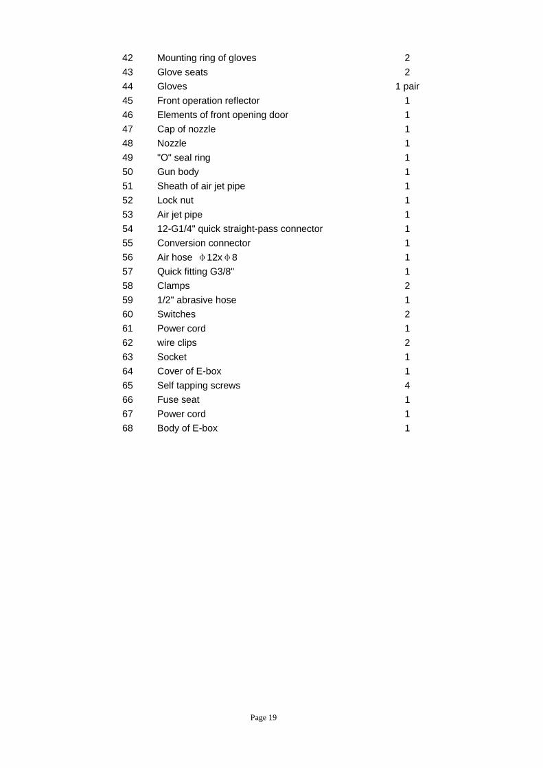
42 Mounting ring of gloves 2
43 Glove seats 2
44 Gloves 1 pair
45 Front operation reflector 1
46 Elements of front opening door 1
47 Cap of nozzle 1
48 Nozzle 1
49 "O" seal ring 1
50 Gun body 1
51 Sheath of air jet pipe 1
52 Lock nut 1
53 Air jet pipe 1
54 12-G1/4" quick straight-pass connector 1
55 Conversion connector 1
56 Air hose φ12xφ8 1
57 Quick fitting G3/8" 1
58 Clamps 2
59 1/2" abrasive hose 1
60 Switches 2
61 Power cord 1
62 wire clips 2
63 Socket 1
64 Cover of E-box 1
65 Self tapping screws 4
66 Fuse seat 1
67 Power cord 1
68 Body of E-box 1
Page 20
Disclaimer of Warranties: Manufacturer, distributor, and ALLSOURCE (“ALLSOURCE”)
makes no warranties with respect to any goods delivered to Buyer or users except as
specifically set forth within this manual. ALLSOURCE MAKES NO IMPLIED
WARRANTIES OF MERCHANTABILITY OR FITNESS FOR A PARTICULAR
PURPOSE WITH RESPECT TO ANY OF THE GOODS, AND Seller EXPRESSLY
DISCLAIMS ANY IMPLIED WARRANTIES AGAINST INFRINGEMENT. ALLSOURCE
WARRANTIES SHALL NOT APPLY TO ANY DAMAGE OR NON-CONFORMITY
RESULTING FROM THE NEGLIGENT OF IMPROPER ASSEMBLY OR USE OF ANY
GOODS BY USERS OR BUYER OR ITS EMPLOYEES OR AGENTS, OR FROM
ALTERATION OR ATTEMPTED REPAIR BY ANY PERSON OTHER THAN
MANUFACTURER. ALL USED, REPAIRED, MODIFIED OR ALTERED ITEMS ARE
PURCHASED AS-IS AND WITH ALL FAULTS.
LIMITED WARRANTY
ALLSOURCE warrants this product to be free from defects in materials or workmanship
for one year after the date of original purchase. This warranty does not include damage
resulting from accident, abuse or misuse of the product. Nor does it apply to parts
subject to abrasive wear, i.e., nozzles, valves, hose connections and hoses. Implied
warranties including those of merchantability and fitness for a particular purpose are
excluded to the extent permitted by law, and any and all implied warranties are
excluded. Reimbursement of original purchase price is the exclusive remedy and
liability for consequential damages under any and all warranties which are also
excluded to the extent exclusion is permitted by law.
Contact us at 1-800-253-9726 or [email protected]
You can learn more about us at www.shindustries.com
S&H Industries Inc.
5200 Richmond Road
Cleveland, Ohio 44146