Embed Size (px)
Citation preview
Signal converters
12 12
Serial data converters
Ser
ial d
ata
Con
verte
rs
In the field of industrial data transmission, various processes of data transmission and interfaces are used today. Already existing systems need to be updated or connected to new devices for continuity of process. When new communication func-tions are not build-in, ABB propose a range of converters to be able to use from the standard RS232 or RS485, to the Ethernet open products or the Optical Fiber.
Ethernet communication is now one of the main features need in open communication, ABB propose the e-ILPH to connect the serial devices to the web world.
Phone: 800.894.0412 - Fax: 888.723.4773 - Web: www.clrwtr.com - Email: [email protected]
Signal converte
rs
12 12
RS-232 RS-485
RS-232 RS-232RS-422
RS-422 RS-422
RS-422
RS-232
RS-232 RS-232 RS-232 RS-232
RS-232 RS-23215 m
max.
1.2 km
max.
15 m
max.
1.2 km
max.
TCPRS-232 RS-485
Modbus / RTUModbus / TCP
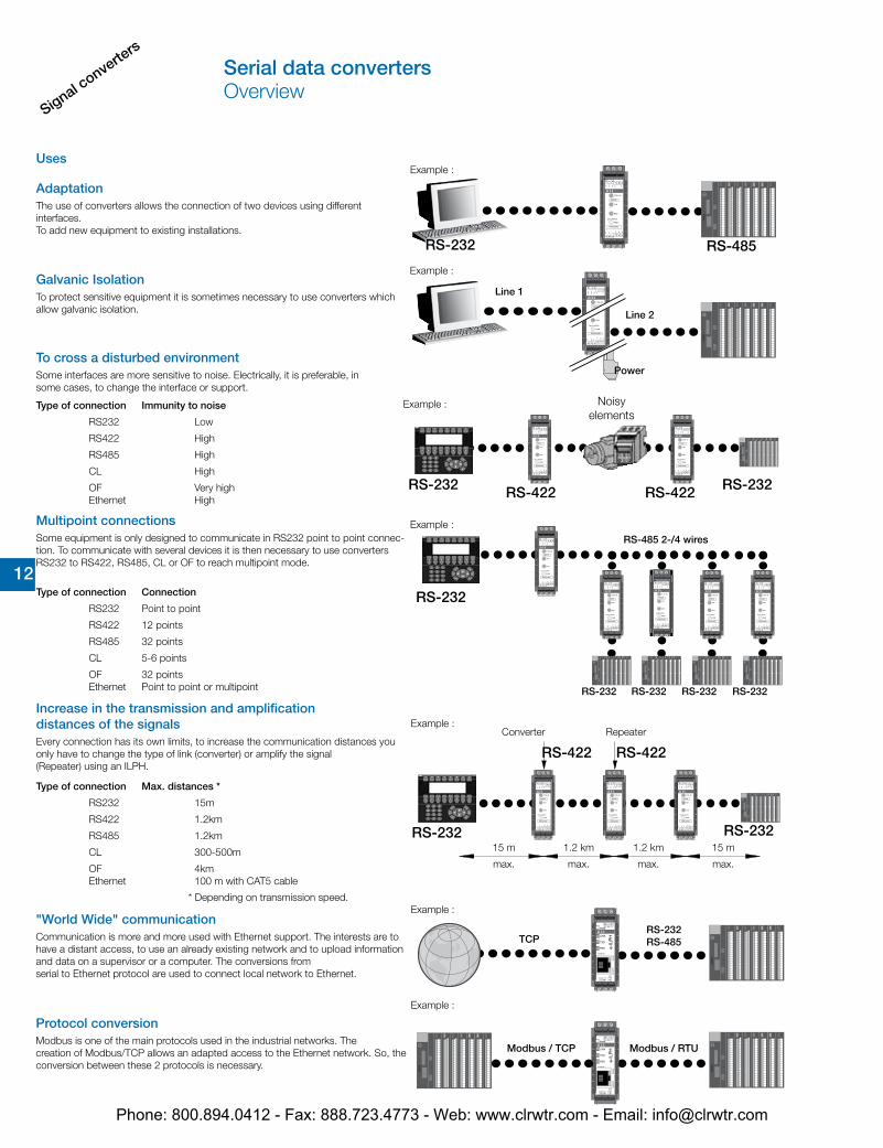
Uses
AdaptationThe use of converters allows the connection of two devices using different interfaces. To add new equipment to existing installations.
Galvanic IsolationTo protect sensitive equipment it is sometimes necessary to use converters which allow galvanic isolation.
Type of connection Immunity to noise
RS232 Low
RS422 High
RS485 High
CL High
OF Very high Ethernet High
To cross a disturbed environmentSome interfaces are more sensitive to noise. Electrically, it is preferable, in some cases, to change the interface or support.
Multipoint connectionsSome equipment is only designed to communicate in RS232 point to point connec-tion. To communicate with several devices it is then necessary to use converters RS232 to RS422, RS485, CL or OF to reach multipoint mode.
Type of connection Connection
RS232 Point to point
RS422 12 points
RS485 32 points
CL 5-6 points
OF 32 points Ethernet Point to point or multipoint
Type of connection Max. distances *
RS232 15m
RS422 1.2km
RS485 1.2km
CL 300-500m
OF 4km Ethernet 100 m with CAT5 cable
Increase in the transmission and amplification distances of the signalsEvery connection has its own limits, to increase the communication distances you only have to change the type of link (converter) or amplify the signal (Repeater) using an ILPH.
* Depending on transmission speed.
Example :
Example :
Line 1
Line 2
Power
Converter Repeater
Example :
Example :
Example :
Noisyelements
RS-485 2-/4 wires
"World Wide" communicationCommunication is more and more used with Ethernet support. The interests are to have a distant access, to use an already existing network and to upload information and data on a supervisor or a computer. The conversions from serial to Ethernet protocol are used to connect local network to Ethernet.
Protocol conversionModbus is one of the main protocols used in the industrial networks. The creation of Modbus/TCP allows an adapted access to the Ethernet network. So, the conversion between these 2 protocols is necessary.
Example :
Example :
Serial data convertersOverview
Phone: 800.894.0412 - Fax: 888.723.4773 - Web: www.clrwtr.com - Email: [email protected]
Signal converters
12 12
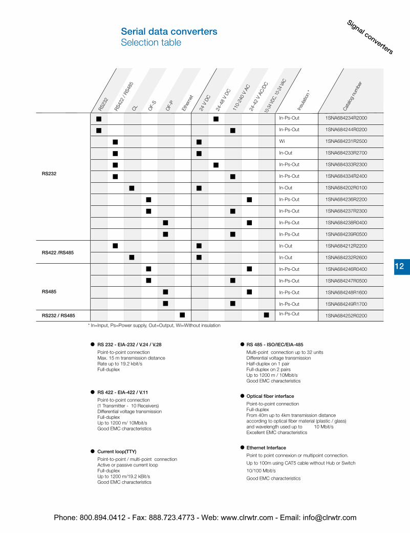
1SNA684234R2000
1SNA684244R0200
1SNA684231R2500
1SNA684233R2700
1SNA684333R2300
1SNA684334R2400
1SNA684202R0100
1SNA684236R2200
1SNA684237R2300
1SNA684238R0400
1SNA684239R0500
1SNA684212R2200
1SNA684232R2600
1SNA684246R0400
1SNA684247R0500
1SNA684248R1600
1SNA684249R1700
1SNA684252R0200
RS232
RS422 /RS485
RS485
RS232 / RS485
RS23
2
RS42
2 / R
S485
24 V
DC
24-4
8 V
DC
110-
240
V AC
24-4
2 V
AC/D
C
Ethe
rnet
10-3
4 VDC
, 10-
24 VA
C
RS 232 - EIA-232 / V.24 / V.28
Point-to-point connection Max. 15 m transmission distance Rate up to 19.2 kbit/s
Full-duplex
RS 422 - EIA-422 / V.11
Point-to-point connection (1 Transmitter - 10 Receivers) Differential voltage transmission
Full-duplex Up to 1200 m/ 10Mbit/s Good EMC characteristics
Current loop(TTY)
Point-to-point / multi-point connection Active or passive current loop
Full-duplex Up to 1200 m/19.2 kBit/s Good EMC characteristics
RS 485 - ISO/IEC/EIA-485
Multi-point connection up to 32 units Differential voltage transmission Half-duplex on 1 pair Full-duplex on 2 pairs Up to 1200 m / 10Mbit/s Good EMC characteristics
Optical fiber interface
Point-to-point connection Full-duplex
From 40m up to 4km transmission distance according to optical fiber material (plastic / glass) and wavelength used up to 10 Mbit/s Excellent EMC characteristics
Ethernet Interface
Point to point connexion or multipoint connection.
Up to 100m using CAT5 cable without Hub or Switch
10/100 Mbit/s
Good EMC characteristics
In-Ps-Out
In-Ps-Out
Wi
In-Out
In-Ps-Out
In-Ps-Out
In-Out
In-Ps-Out
In-Ps-Out
In-Ps-Out
In-Ps-Out
In-Out
In-Out
In-Ps-Out
In-Ps-Out
In-Ps-Out
In-Ps-Out
In-Ps-Out
Insu
latio
n *
Cat
alog
num
ber
* In=Input, Ps=Power supply, Out=Output, Wi=Without insulation
CL
OF-
S
OF-
P
Serial data convertersSelection table
Phone: 800.894.0412 - Fax: 888.723.4773 - Web: www.clrwtr.com - Email: [email protected]
Signal converte
rs
12 12
ILPH RS 232 - 485 / EthernetIsolated RS232 or/and RS485 to Ethernet converter• Triple galvanic isolation• RS232 on SUBD 9 points or screw connectors• RS485 on removable screw connectors• Ethernet 10/100 Mbit/s, RJ45 connector• Power supply 10-34 VDC et 10-24 VAC• Possible to have a redundant 10-34 VDC power supply• Economic with low consumption• Up to 100m with CAT5 cable without Hub or Switch• Good EMC characteristics• Up to 2 Modbus®\TCP Masters
Available modes:• Modbus®\TCP to Modbus® RTU conversion• Transparent Client or Server mode• SMTP mode (Mail send)
Standards: TPC/IP, TELNET, DHCP, FTP• Specifics functions in Modbus® protocol:• Concentrator (Asynchronous mode) up to 1200 words• AC31 programming
Modbus® Easy Net mode : this mode could be used to exchange data without a Modbus®/TCP master. The data are logged in a table and could be distributed to one or all the others e-ILPH participants on Ethernet.
ILPH RS 232 / RS 422 - 485
RS 232 to RS 422-485 serial link without isolation• Economic version without isolation• Baudrate up to 38.4 kbit/s • Transmission distance up to 1200 m • RS 485 1 or 2 pair handling• Usable in "noisy" environments• 24 V DC power supply• CE mark
ILPH RS 232 / RS 422 - 485
Galvanic isolated converter for RS 232 to RS 422-485 serial links.• Galvanic isolation between input/output and output/power supply• Baudrate up to 38.4 kbit/s • Transmission distance up to 1200 m • RS 485 1 or 2 pair handling• Usable in "noisy" environments• 24 V DC power supply• CE mark
ILPH RS 232 / RS 422 - 485• 3 way galvanic isolated converter for RS 232 to RS 422-485 serial links.• 3 way galvanic isolation between power supply and input/output• RS 485 switch on 2 or 4 wires• Baudrate up to 38.4 kbit/s• Transmission distance up to 1200 m• RS 485 1 or 2 pair handling• Usable in "noisy" environments• 24...48 V DC and 115...230 V AC power supply• CE marking
ILPH RS 232 / RS 2323 way galvanic isolator between RS 232 serial interface and another RS 232 serial interface.• Ensures triple insulation between the 2 serial interfaces and between each and power supply• Baudrate up to 19.2 kbit/s (up to 64 kbit/s depending on cable)• Transmission distance up to 15 m• Can be used in "noisy" environments• Power supply from 24...48 V DC and 115...230 V AC CE marking
ILPH RS 422 - 485 / RS 422 - 485Galvanic isolated connection between an RS 422-485 (1 or 2 pairs) and an RS 422 485 (1 or 2 pairs) serial link. It amplifies the signal beyond the 1200 m limit distance of the RS 422-485 and only needs a minimum of 1.5 character delay time to switch off the RS 485 drivers.
• Galvanic isolation between power supply/output and input/output• Baudrate up to 500 kbit/s (up to 200 m)• Transmission distance up to 1200m at 38.4 kbit/s• Usable in "noisy" environments• 2/4 wires automatic handling• 24 V DC power supply• CE mark
ILPH RS 232 / FO• 3 way galvanic isolated Converter for RS 232 to optical fiber serial link glass (S) or plastic (P). • 3 way galvanic isolation between power supply and input/output • Baud rate up to 115.2 kbit/s• Available for glass or plastic fiber• Transmission distance up to 4 km• Usable in "very noisy" environments• 20...42 V AC/DC and 110...240 V AC/DC power supply• CE markedILPH RS 485 / FO
3 way galvanic isolated converter for RS 485 (1 pair) to optical fiber serial link glass (S) or plastic (P).
• 3 way galvanic isolation between power supply and input/output • Baud rate up to 1.5 Mbit/s• Available for glass fiber or plastic fiber• Transmission distance up to 4 km • Usable in "very noisy" environments• 20...42 V AC/DC and 110...240 V AC/DC power supply• CE marked
Galvanic isolated converter for current loop to RS 422-485 (1 or 2 pairs) serial link. • Galvanic isolation between power supply/current loop and RS 422-485/current loop• Active/passive 0...20 mA / 4...20 mA selectable
Positive or negative logic selectable• Baudrate up to 38.4 kbit/s (up to 2400 m) Transmission distance up to 2400 m (1200 m RS 485 and 1200 m current loop)
• Usable in "noisy" environments• 24 V DC power supply • CE marking
ILPH CL / RS 422 - 485
Galvanic isolated Converter for RS 232 to current loop serial link. • Galvanic isolation between power supply/current loop and RS 232/current loop• Active/Passive 0...20 mA / 4...20 mA selectable
Positive or negative logic selectable• Baudrate up to 38.4 kbit/s • Transmission distance up to 1200 m • Usable in "noisy" environments• 24 V DC power supply • CE marking
ILPH RS 232 / CL
Serial data convertersBenefits and advantages
Phone: 800.894.0412 - Fax: 888.723.4773 - Web: www.clrwtr.com - Email: [email protected]
Signal converters
12 12
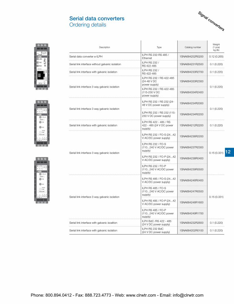
Description Type Catalog numberWeight(1 pce)kg (lb)
Serial data converter e-ILPHILPH RS 232-RS 485 / Ethernet
1SNA684252R0200 0.12 (0.265)
Serial link interface without galvanic isolationILPH RS 232 / RS 422-485
1SNA684231R2500 0.1 (0.220)
Serial link interface with galvanic isolationILPH RS 232 / RS 422-485
1SNA684233R2700 0.1 (0.220)
Serial link interface 3 way galvanic isolation
ILPH RS 232 / RS 422-485 (24-48 V DC power supply)
1SNA684333R2300
0.1 (0.220)ILPH RS 232 / RS 422-485 (115-230 V DC power supply)
1SNA684334R2400
Serial link interface 3 way galvanic isolation
ILPH RS 232 / RS 232 (24-48 V DC power supply)
1SNA684234R2000
0.1 (0.220)ILPH RS 232 / RS 232 (115-230 V DC power supply)
1SNA684234R0200
Serial link interface with galvanic isolationILPH RS 422 - 485 / RS 422 - 485 (24 V DC power supply)
1SNA684212R2200 0.1 (0.220)
Serial link interface 3 way galvanic isolation
ILPH RS 232 / FO-S (24...42 V AC/DC power supply)
1SNA684236R2200
0.15 (0.331)
ILPH RS 232 / FO-S (110...240 V AC/DC power supply)
1SNA684237R2300
ILPH RS 232 / FO-P (24...42 V AC/DC power supply)
1SNA684238R0400
ILPH RS 232 / FO-P (110...240 V AC/DC power supply)
1SNA684239R0500
Serial link interface 3 way galvanic isolation
ILPH RS 485 / FO-S (24...42 V AC/DC power supply)
1SNA684246R0400
0.15 (0.331)
ILPH RS 485 / FO-S (110...240 V AC/DC power supply)
1SNA684247R0500
ILPH RS 485 / FO-P (24...42 V AC/DC power supply)
1SNA684248R1600
ILPH RS 485 / FO-P (110...240 V AC/DC power supply)
1SNA684249R1700
Serial link interface with galvanic isoaltionILPH BdC /RS 422 - 485 (24 V DC power supply)
1SNA684232R2600 0.1 (0.220)
Serial link interface with galvanic isolationILPH RS 232 BdC (24 V DC power supply)
1SNA684202R0100 0.1 (0.220)
Serial data convertersOrdering details
Phone: 800.894.0412 - Fax: 888.723.4773 - Web: www.clrwtr.com - Email: [email protected]
Signal converte
rs
12 12
center of rail
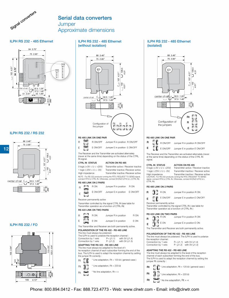
ILPH RS 232 - 485 Ethernet
ILPH RS 232 / RS 232
ILPH RS 232 / FO
ILPH RS 232 - 485 Ethernet (without isolation)
ILPH RS 232 - 485 Ethernet (isolated)
RRt E
center of rail
Configuration ofthe jumper
R
E
R
E
RS 485 LINK ON ONE PAIR
R ON/OFF Jumper R in position R ON/OFF
E ON/OFF Jumper E in position E ON/OFF
The Receiver and the Transmitter are activated alternately (never at the same time) depending on the status of the CTRL IN signal.
CTRL IN STATUS ACTION ON RS 485
0 logic (+3V ≤ U ≤ +25V) Transmitter active / Receiver inactive1 logic (-25V ≤ U ≤ -3V) Transmitter inactive /Receiver activeHigh impedance Transmitter inactive /Receiver activeNOTE : For RS 232 products running the RTS ( REQUEST TO SEND) signal, connect RTS to CTRL IN. Otherwise, connect M (RxD ILPH) to L (CTRL IN).
RS 485 LINK ON 2 PAIRS
R ON Jumper R in position R ON
E ON/OFF Jumper E in position E ON/OFF
Receiver permanently active
Transmitter controlled by the signal CTRL IN (see table for Transmitter operation as a function of CTRL IN)
RS 422 LINK ON TWO PAIRS
R ON Jumper R in position R ON
E ON Jumper E in position E ON
The Transmitter and Receiver are both permanently active.
POLARIZATION OF THE RS 422 - RS 485 LINEThe line must always be polarized. The ILPH is used to polarize the reception channel :Connection by 1 wire P+ (J1.1) with 5V (J1.4)Connection by 1 wire P- (J1.2) with 0V (J1.3)
ADAPTING THE RS 422 - RS 485 LINEThe line must always be adapted to the level of t he reception channel of each subscriber forming the end of the bus. The ILPH is used to adapt the reception channel by setting the jumper Rt correctly :
* Line adaptation, Rt = 120 Ω ( general case )
* Line adaptation, Rt = 220 Ω
* No line adaptation, Rt = ∝
Rt
Rt
Rt
R
E
R
E
R
E
R
E
Rt
Rt
Rt
RS 485 LINK ON ONE PAIR
R ON/OFF Jumper R in position R ON/OFF
E ON/OFF Jumper E in position E ON/OFF
The Receiver and the Transmitter are activated alternately (never at the same time) depending on the status of the CTRL IN signal.
CTRL IN STATUS ACTION ON RS 4850 logic (+3V ≤ U ≤ +25V) Transmitter active / Receiver inactive1 logic (-25V ≤ U ≤ -3V) Transmitter inactive / Receiver activeHigh impedance Transmitter inactive / Receiver activeCAUTION : For RS 232 products running the RTS ( REQUEST TO SEND) signal, connect RTS to CTRL IN. Otherwise, connect M (RxD ILPH) to L (CTRL IN).
RS 485 LINK ON 2 PAIRS
R ON Jumper R in position R ON
E ON/OFF Jumper E in position E ON/OFF
Receiver permanently activeTransmitter controlled by the signal CTRL IN ( see table for Transmitter operation as a function of CTRL IN )
RS 422 LINK ON TWO PAIRSR ON Jumper R in position R ON
E ON Jumper E in position E ON
The Transmitter and Receiver are both permanently active.
POLARIZATION OF THE RS 422 - RS 485 LINEThe line must always be polarized. The ILPH is used to polarize the reception channel :Connection by 1 wire P+ (J1.1) with 5V (J1.4)Connection by 1 wire P- (J1.2) with 0V (J1.3)
ADAPTING THE RS 422 - RS 485 LINEThe line must always be adapted to the level of the reception channel of each subscriber forming the end of the bus.The ILPH is used to adapt the reception channel by setting the jumper Rt correctly :
* Line adaptation, Rt = 120 Ω ( general case )
* Line adaptation, Rt = 220 Ω
* No line adaptation, Rt = ∝
R
Rt
E
Configuration ofthe jumpers
center of rail
center of rail
Serial data convertersJumperApproximate dimensions
Phone: 800.894.0412 - Fax: 888.723.4773 - Web: www.clrwtr.com - Email: [email protected]
Signal converters
12 12
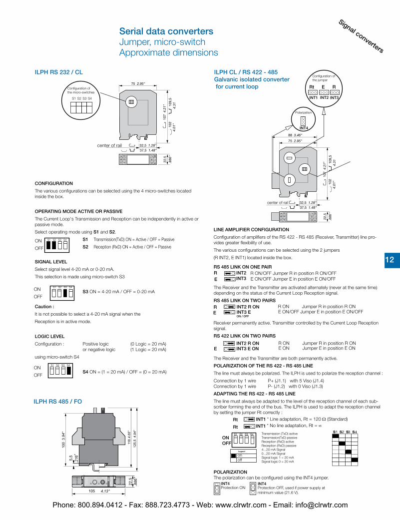
ILPH RS 232 / CL
ILPH RS 485 / FO
ILPH CL / RS 422 - 485 Galvanic isolated converter for current loop
CONFIGURATION
The various configurations can be selected using the 4 micro-switches located inside the box.
OPERATING MODE ACTIVE OR PASSIVE
The Current Loop's Transmission and Reception can be independently in active or passive mode.
Select operating mode using S1 and S2.
S1 Transmission(TxD) ON = Active / OFF = Passive
S2 Reception (RxD) ON = Active / OFF = Passive
SIGNAL LEVEL
Select signal level 4-20 mA or 0-20 mA.
This selection is made using micro-switch S3
S3 ON = 4-20 mA / OFF = 0-20 mA
Caution :
It is not possible to select a 4-20 mA signal when the
Reception is in active mode.
LOGIC LEVEL
Configuration : Positive logic (0 Logic = 20 mA)or negative logic (1 Logic = 20 mA)
using micro-switch S4
S4 ON = (1 = 20 mA) / OFF = (0 = 20 mA)
ON
OFF
S1 S2 S3 S4
ON
OFF
S1 S2 S3 S4
INT4
S1 S2 S3 S4
ON OFF
INT4
LINE AMPLIFIER CONFIGURATION
Configuration of amplifiers of the RS 422 - RS 485 (Receiver, Transmitter) line pro-vides greater flexibility of use.
The various configurations can be selected using the 2 jumpers
(R INT2, E INT1) located inside the box.
RS 485 LINK ON ONE PAIR
The Receiver and the Transmitter are activated alternately (never at the same time) depending on the status of the Current Loop Reception signal.
RS 485 LINK ON TWO PAIRS
Receiver permanently active. Transmitter controlled by the Current Loop Reception signal.
RS 422 LINK ON TWO PAIRS
The Receiver and the Transmitter are both permanently active.
POLARIZATION OF THE RS 422 - RS 485 LINE
The line must always be polarized. The ILPH is used to polarize the reception channel :
Connection by 1 wire P+ (J1.1) with 5 Viso (J1.4)Connection by 1 wire P- (J1.2) with 0 Viso (J1.3)
ADAPTING THE RS 422 - RS 485 LINE
The line must always be adapted to the level of the reception channel of each sub-scriber forming the end of the bus. The ILPH is used to adapt the reception channel by setting the jumper Rt correctly :
POLARIZATIONThe polarization can be configured using the INT4 jumper.
Protection ON Protection OFF, used if power supply at
minimum value (21.6 V).
ER
E ON/OFF Jumper E in position E ON/OFF R ON/OFF Jumper R in position R ON/OFF
EINT2 R ONINT3 E ON / OFF
R R ON Jumper R in position R ONE ON/OFF Jumper E in position E ON/OFF
EINT2 R ON INT3 E ON
R ON Jumper R in position R ONE ON Jumper E in position E ON
Rt
Rt INT1
* Line adaptation, Rt = 120 Ω (Standard)* No line adaptation, Rt = ∞
Transmission (TxD) active Transmission(TxD) passive Reception (RxD) active Reception (RxD) passive 4...20 mA Signal 0...20 mA Signal Signal logic 1 = 20 mASignal logic 0 = 20 mA
onoff
Legend
INT1 INT2 INT3
Rt E R
INT4
Configuration of the jumper
Polarization
center of rail
Serial data convertersJumper, micro-switchApproximate dimensions
Configuration of the micro-switches
center of rail
S1 S2 S3 S4
ON
OFF
S1 S2 S3 S4
INT1
INT2INT3
Phone: 800.894.0412 - Fax: 888.723.4773 - Web: www.clrwtr.com - Email: [email protected]
Signal converte
rs
12 12
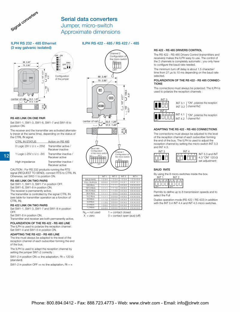
ILPH RS 232 - 485 Ethernet (3 way galvanic isolated)
ILPH RS 422 - 485 / RS 422 / - 485
Configurationof the jumper
center of rail
RS 485 LINK ON ONE PAIR
Set SW1-1, SW1-3, SW1-6, SW1-7 and SW1-8 to position ON.
The receiver and the transmitter are activated alternate-ly (never at the same time), depending on the status of the CTRL IN signal.
CTRL IN STATUS Action on RS 485
0 Logic (3V ≤ U ≤ + 25V) Transmitter active / Receiver inactive
1 Logic (-25V ≤ U ≤ -3V) Transmitter inactive /Receiver active
High impedance Transmitter inactive /Receiver active
CAUTION : For RS 232 products running the RTS signal (REQUEST TO SEND), connect RTS to CTRL IN. Otherwise, set SW2-1 to position ON.
RS 485 LINK ON TWO PAIRSSet SW1-1, SW1-3, SW1-7 in position OFF.Set SW1-6, SW1-8 in position ON.The receiver is permanently active.The transmitter is controlled by the signal CTRL IN(see table for transmitter operation as a fonction of CTRL IN).
RS 422 LINK ON TWO PAIRSSet SW1-1, SW1-3, SW1-7 and SW1-8 in position OFF.Set SW1-6 in position ON.Transmitter and receiver are both permanently active.
POLARIZATION OF THE RS 422 - RS 485 LINEThe ILPH is used to polarize the reception channel :Set SW1-4 and SW1-5 in position ON.
ADAPTING THE RS 422 - RS 485 LINEThe line must always be adapted to the level of the reception channel of each subscriber forming the end of the bus.
The ILPH is used to adapt the reception channel by setting the jumper SW1-2 correctly :
SW1-2 in position ON ⇒ line adaptation, Rt = 120 Ω (standard)
SW1-2 in position OFF ⇒ no line adaptation, Rt = ∝
OFF
INT 11 2 3 4 1 2 3 4
INT 2
OFF
OFF
INT 4 1 2 3 4 5 6
OFF
INT 31 2 3 4
center of rail
Channel 1Configuration of the micro-switch
Channel 2Configuration of the micro-switch
Baud rateConfiguration of the micro-switch
INT 1 1 2 3 40 0 0 01 1 1 11 1 1 11 1 1 11 1 1 11 1 1 11 1 1 01 1 0 01 0 0 00 0 0 0
INT 21 2 3 40 0 0 01 1 1 11 1 1 01 1 0 01 0 0 00 0 0 00 0 0 00 0 0 00 0 0 00 0 0 0
INT 3 1 2 3 4X X X 1X X X 0X X X 0X X X 0X X X 0X X X 0X X X 0X X X 0X X X 0X X X 0
INT 4 1 2 3 4 5 6X X X 1 0 1X X X 0 0 0X X X 0 0 0X X X 0 0 0X X X 0 0 0X X X 0 0 0X X X 0 0 0X X X 0 0 0X X X 0 0 0X X X 0 0 0
Nu = not used X = zero
1 = contact closed0 = contact open (aus) (off)
BAUD RATEFULL DUPLEX
500 Kb/s187.5 Kb/s93.75 Kb/s38.4 Kb/s19.2 Kb/s9.6 Kb/s4.8 Kb/s2.4 Kb/s1.2 Kb/s
OFF
1 2 3 4 INT 3
INT 4
INT 3.1INT 3.2
INT 4.1
INT 4.2
"ON", polarizes the reception channel Rx2
"ON", polarizes the reception channel Rx1
RS 422 - RS 485 DRIVERS CONTROL
The RS 422 - RS 485 Drivers Control (transmitters and receivers) makes the ILPH easy to use. The control of the 2 channels is completely automatic ; you only have to configure the baud rate needed.
The minimum turn off delay is about 1.5 character/time from 27 µs to 10 ms depending on the baud rate selected.
POLARIZATION OF THE RS 422 - RS 485 CONNEC-TIONS
The connections must always be polarized. The ILPH is used to polarize the reception channels :
ADAPTING THE RS 422 - RS 485 CONNECTIONS
The connections must always be adjusted to the level of the reception channel of each subscriber forming the end of the bus. The ILPH is used to adjust the reception channel by setting the micro-switch INT 3.3 and INT 4.3.
BAUD RATE
By using the 8 micro-switches inside the box.
Permits to define up to 8 transmission speeds and to select the Full
Duplex operation mode (RS 422 / RS 422) in addition with the INT 3.4 INT 4.4 and INT 4.5 micro switches.
INT 3.3 and INT 4.3 "ON" 120 Ω set adjustment
Serial data convertersJumper, micro-switchApproximate dimensions
OFF
1 2 3 4 5 6
INT 1 INT 21 2 3 4 1 2 3 4
OFF OFF
INT 3 INT 41 2 3 4 5 61 2 3 4
OFF OFF
Phone: 800.894.0412 - Fax: 888.723.4773 - Web: www.clrwtr.com - Email: [email protected]
Signal converters
12 12
Technical dataData at Ta = 25 °C and rated values, unless otherwise indicated
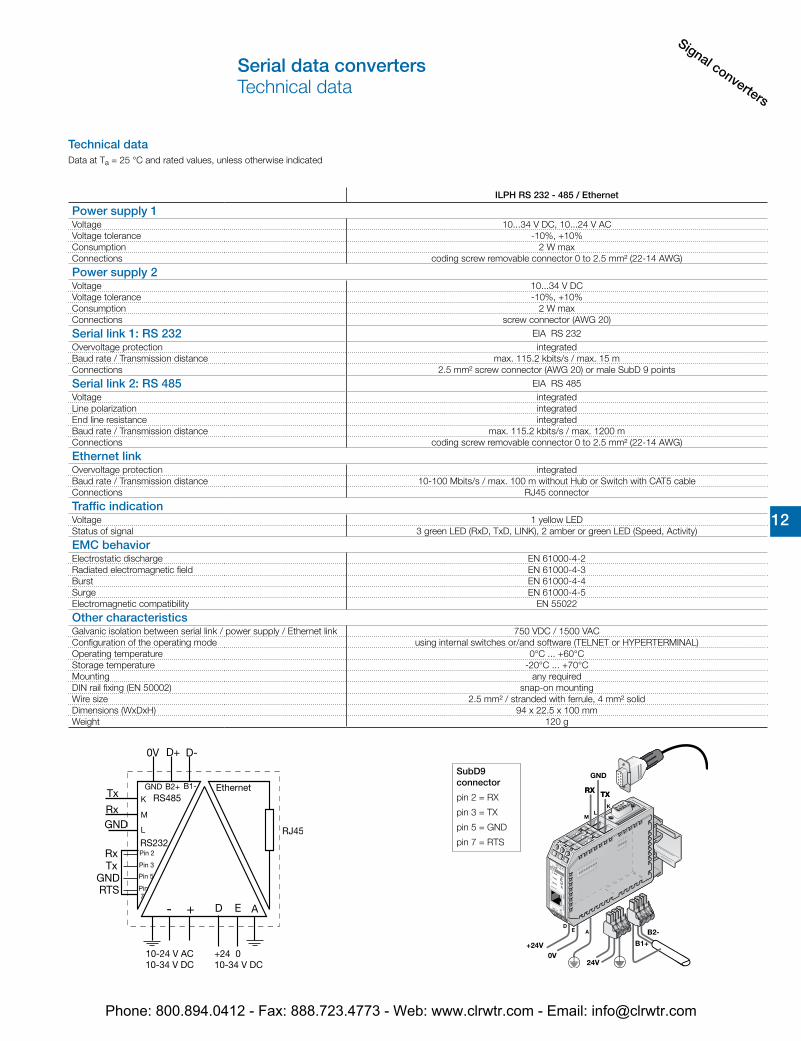
ILPH RS 232 - 485 / Ethernet
Power supply 1Voltage 10...34 V DC, 10...24 V ACVoltage tolerance -10%, +10%Consumption 2 W maxConnections coding screw removable connector 0 to 2.5 mm² (22-14 AWG)
Power supply 2Voltage 10...34 V DCVoltage tolerance -10%, +10%Consumption 2 W maxConnections screw connector (AWG 20)
Serial link 1: RS 232 EIA RS 232Overvoltage protection integratedBaud rate / Transmission distance max. 115.2 kbits/s / max. 15 mConnections 2.5 mm² screw connector (AWG 20) or male SubD 9 points
Serial link 2: RS 485 EIA RS 485Voltage integratedLine polarization integratedEnd line resistance integratedBaud rate / Transmission distance max. 115.2 kbits/s / max. 1200 mConnections coding screw removable connector 0 to 2.5 mm² (22-14 AWG)
Ethernet linkOvervoltage protection integratedBaud rate / Transmission distance 10-100 Mbits/s / max. 100 m without Hub or Switch with CAT5 cableConnections RJ45 connector
Traffic indicationVoltage 1 yellow LEDStatus of signal 3 green LED (RxD, TxD, LINK), 2 amber or green LED (Speed, Activity)
EMC behaviorElectrostatic discharge EN 61000-4-2Radiated electromagnetic field EN 61000-4-3Burst EN 61000-4-4Surge EN 61000-4-5Electromagnetic compatibility EN 55022
Other characteristicsGalvanic isolation between serial link / power supply / Ethernet link 750 VDC / 1500 VACConfiguration of the operating mode using internal switches or/and software (TELNET or HYPERTERMINAL)Operating temperature 0°C ... +60°CStorage temperature -20°C ... +70°CMounting any requiredDIN rail fixing (EN 50002) snap-on mountingWire size 2.5 mm² / stranded with ferrule, 4 mm² solidDimensions (WxDxH) 94 x 22.5 x 100 mmWeight 120 g
+24V0V
24V
TXTX
GND
RXRX
B1+
B2-
M
JH
G
ML
K
DE
A
GND
RX
TX
Ethernet
LINK
TXD
RXD
e-IL
PHSP
EED
PWR
ACTI
VITY
M LK
JH
G
ML
K
43
21
ON
43
21
ON56
78
KL
DE A
SubD9 connector
pin 2 = RX
pin 3 = TX
pin 5 = GND
pin 7 = RTS
Serial data convertersTechnical data
Phone: 800.894.0412 - Fax: 888.723.4773 - Web: www.clrwtr.com - Email: [email protected]
Signal converte
rs
12 12
Technical data
Data at Ta = 25 °C and rated values, unless otherwise indicated
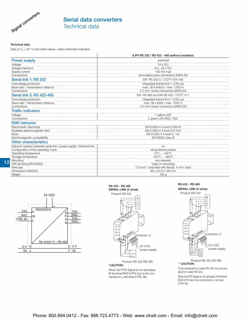
ILPH RS 232 / RS 422 - 485 (without isolation)
Power supply polarizedVoltage 24 V DCVoltage tolerance 8.5...28 V DCSupply current 100 mA maxConnections removable screw connectors (AWG 20)
Serial link 1: RS 232 EIA RS 232 C / CCITT V24 V28Overvoltage protection integrated (transil 8 kV 1.2/50 µs)Baud rate / Transmission distance max. 38.4 kbits/s / max. 1200 mConnections 2.5 mm² screw connectors (AWG 20)
Serial link 2: RS 422-485 EIA RS 485 and EIA RS 422 / CCITT V11Overvoltage protection integrated (transil 8 kV 1.2/50 µs)Baud rate / Transmission distance max. 38.4 kbits / max. 1200 mConnections 2.5 mm² screw connectors (AWG 20)
Traffic indicationVoltage 1 yellow LEDConnections 2 green LED (RxD, TxD)
EMC behaviorElectrostatic discharge EN 61000-4-2 level 3 6/8 kVRadiated electromagnetic field EN 61000-4-3 level 310 V/mBurst EN 61000-4-4 level 3 1 kVElectromagnetic compatibility EN 55022 class B
Other characteristicsGalvanic isolation between serial link / power supply / Ethernet link noConfiguration of the operating mode using internal jumperOperating temperature 0°C ... +50°CStorage temperature -25°C ... +80°CMounting any requiredDIN rail fixing (EN 50002) snap-on mountingWire size 2.5 mm² / stranded with ferrule, 4 mm² solidDimensions (WxDxH) 88 x 22.5 x 100 mmWeight 100 g
*CAUTION :
When the RTS Signal is not activated, M terminal (RxD ILPH) has to be con-nected to L terminal (CTRL IN).
RS 422 - RS 485SERIAL LINK (2 wires)
Product RS 232
Connector J1
24 V DCpower supply
Product RS 422-RS 485** CAUTION :
To be connected to 2 wired RS 485 only (not pos-sible for 4 wired RS 422).
When the RTS Signal is not activated, M terminal (RxD ILPH) has to be connected to L terminal (CTRL IN).
RS 422 - RS 485
SERIAL LINK (4 wires)Product RS 232
Connector J1
24 V DCpower supply
Product RS 422-RS 485
Serial data convertersTechnical data
Phone: 800.894.0412 - Fax: 888.723.4773 - Web: www.clrwtr.com - Email: [email protected]
Signal converters
12 12
Technical data
Data at Ta = 25 °C and rated values, unless otherwise indicated
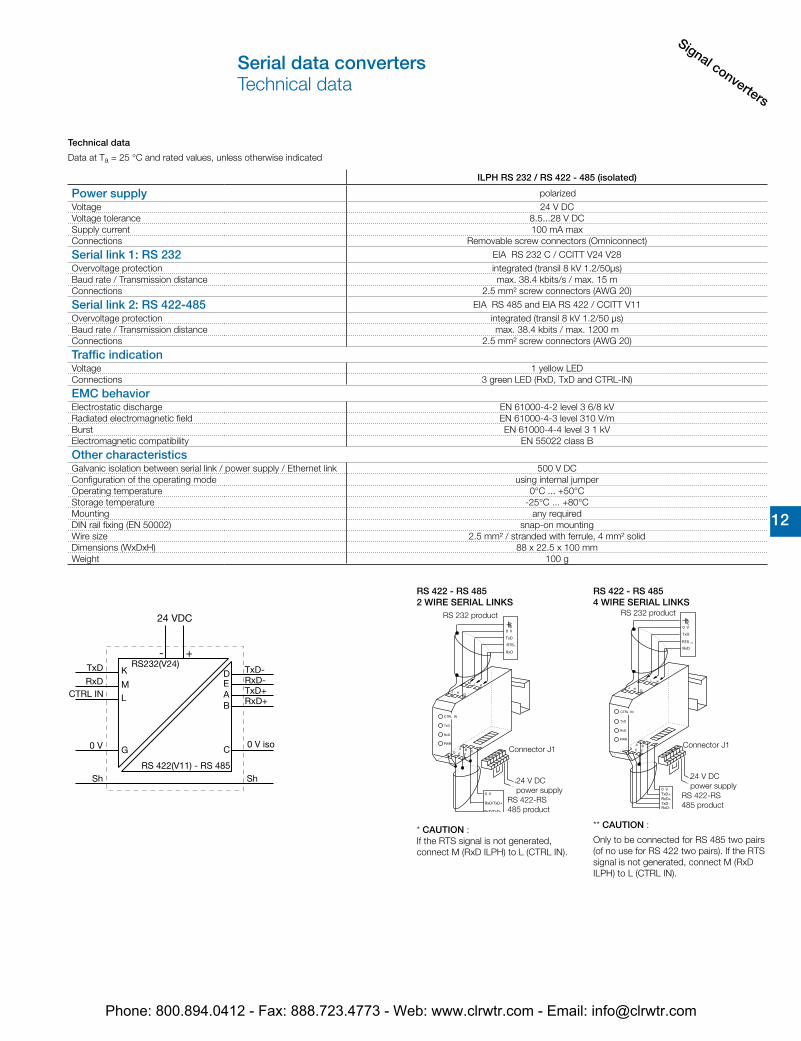
ILPH RS 232 / RS 422 - 485 (isolated)
Power supply polarizedVoltage 24 V DCVoltage tolerance 8.5...28 V DCSupply current 100 mA maxConnections Removable screw connectors (Omniconnect)
Serial link 1: RS 232 EIA RS 232 C / CCITT V24 V28Overvoltage protection integrated (transil 8 kV 1.2/50µs)Baud rate / Transmission distance max. 38.4 kbits/s / max. 15 mConnections 2.5 mm² screw connectors (AWG 20)
Serial link 2: RS 422-485 EIA RS 485 and EIA RS 422 / CCITT V11Overvoltage protection integrated (transil 8 kV 1.2/50 µs)Baud rate / Transmission distance max. 38.4 kbits / max. 1200 mConnections 2.5 mm² screw connectors (AWG 20)
Traffic indicationVoltage 1 yellow LEDConnections 3 green LED (RxD, TxD and CTRL-IN)
EMC behaviorElectrostatic discharge EN 61000-4-2 level 3 6/8 kVRadiated electromagnetic field EN 61000-4-3 level 310 V/mBurst EN 61000-4-4 level 3 1 kVElectromagnetic compatibility EN 55022 class B
Other characteristicsGalvanic isolation between serial link / power supply / Ethernet link 500 V DCConfiguration of the operating mode using internal jumperOperating temperature 0°C ... +50°CStorage temperature -25°C ... +80°CMounting any requiredDIN rail fixing (EN 50002) snap-on mountingWire size 2.5 mm² / stranded with ferrule, 4 mm² solidDimensions (WxDxH) 88 x 22.5 x 100 mmWeight 100 g
** CAUTION :
Only to be connected for RS 485 two pairs (of no use for RS 422 two pairs). If the RTS signal is not generated, connect M (RxD ILPH) to L (CTRL IN).
* CAUTION : If the RTS signal is not generated, connect M (RxD ILPH) to L (CTRL IN).
RS 422 - RS 4852 WIRE SERIAL LINKS
RS 422 - RS 4854 WIRE SERIAL LINKS
Connector J1
24 V DCpower supply
RS 422-RS 485 product
RS 232 product
Connector J1
24 V DCpower supply
RS 422-RS 485 product
RS 232 product
Serial data convertersTechnical data
Phone: 800.894.0412 - Fax: 888.723.4773 - Web: www.clrwtr.com - Email: [email protected]
Signal converte
rs
12 12
Technical data
Data at Ta = 25 °C and rated values, unless otherwise indicated
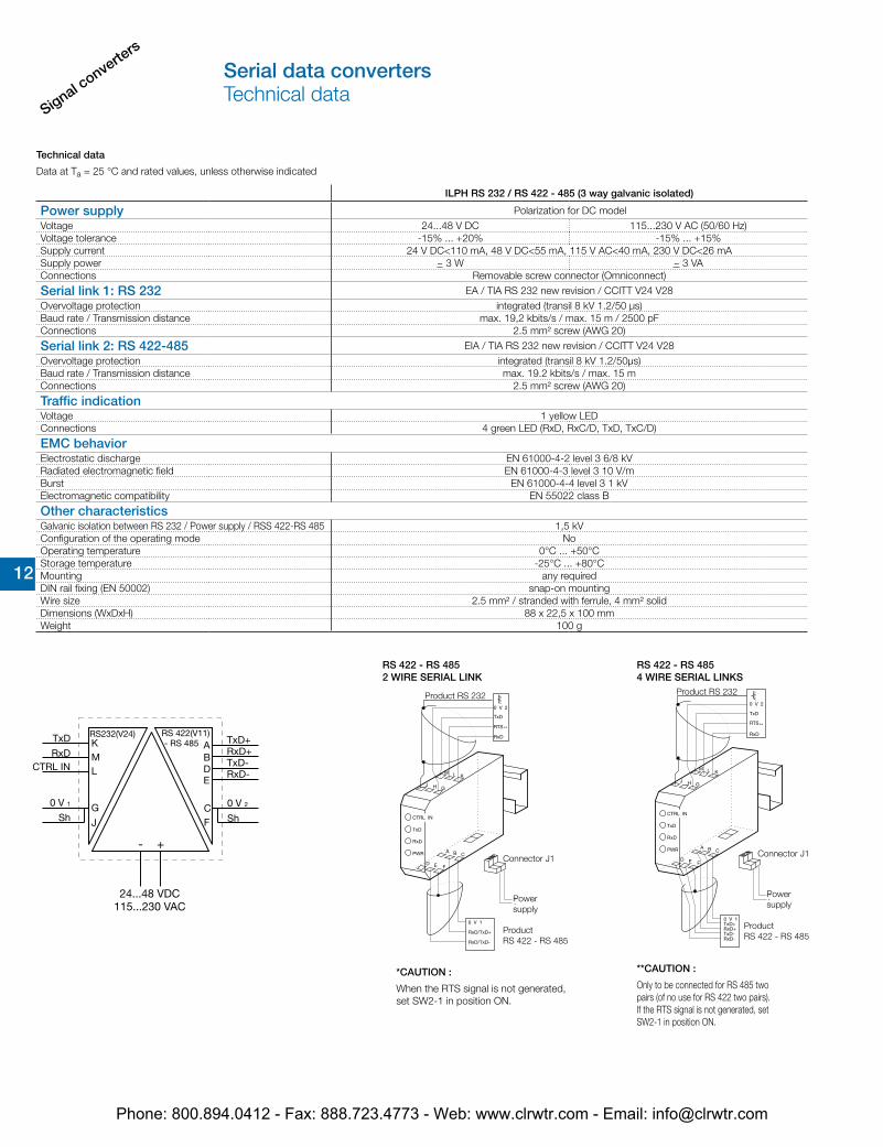
ILPH RS 232 / RS 422 - 485 (3 way galvanic isolated)
Power supply Polarization for DC modelVoltage 24...48 V DC 115...230 V AC (50/60 Hz)Voltage tolerance -15% ... +20% -15% ... +15%Supply current 24 V DC<110 mA, 48 V DC<55 mA, 115 V AC<40 mA, 230 V DC<26 mASupply power ~ 3 W ~ 3 VAConnections Removable screw connector (Omniconnect)
Serial link 1: RS 232 EA / TIA RS 232 new revision / CCITT V24 V28Overvoltage protection integrated (transil 8 kV 1.2/50 μs)Baud rate / Transmission distance max. 19,2 kbits/s / max. 15 m / 2500 pFConnections 2.5 mm² screw (AWG 20)
Serial link 2: RS 422-485 EIA / TIA RS 232 new revision / CCITT V24 V28Overvoltage protection integrated (transil 8 kV 1.2/50μs)Baud rate / Transmission distance max. 19.2 kbits/s / max. 15 mConnections 2.5 mm² screw (AWG 20)
Traffic indicationVoltage 1 yellow LEDConnections 4 green LED (RxD, RxC/D, TxD, TxC/D)
EMC behaviorElectrostatic discharge EN 61000-4-2 level 3 6/8 kVRadiated electromagnetic field EN 61000-4-3 level 3 10 V/mBurst EN 61000-4-4 level 3 1 kVElectromagnetic compatibility EN 55022 class B
Other characteristicsGalvanic isolation between RS 232 / Power supply / RSS 422-RS 485 1,5 kVConfiguration of the operating mode NoOperating temperature 0°C ... +50°CStorage temperature -25°C ... +80°CMounting any requiredDIN rail fixing (EN 50002) snap-on mountingWire size 2.5 mm² / stranded with ferrule, 4 mm² solidDimensions (WxDxH) 88 x 22,5 x 100 mmWeight 100 g
RS 422 - RS 4852 WIRE SERIAL LINK
**CAUTION :
Only to be connected for RS 485 twopairs (of no use for RS 422 two pairs).If the RTS signal is not generated, setSW2-1 in position ON.
*CAUTION :
When the RTS signal is not generated, set SW2-1 in position ON.
RS 422 - RS 4854 WIRE SERIAL LINKS
Product RS 232
Connector J1
Powersupply
ProductRS 422 - RS 485
Product RS 232
Connector J1
Powersupply
ProductRS 422 - RS 485
Serial data convertersTechnical data
Phone: 800.894.0412 - Fax: 888.723.4773 - Web: www.clrwtr.com - Email: [email protected]
Signal converters
12 12
Technical data
Data at Ta = 25 °C and rated values, unless otherwise indicated
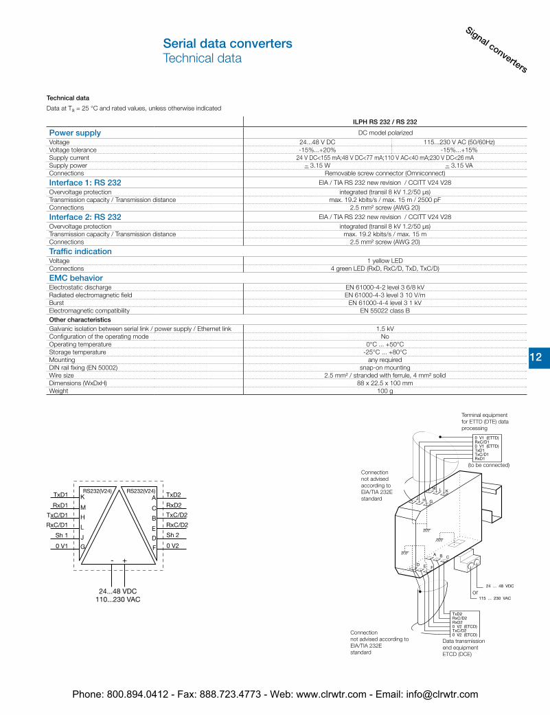
ILPH RS 232 / RS 232
Power supply DC model polarizedVoltage 24...48 V DC 115...230 V AC (50/60Hz)Voltage tolerance -15%...+20% -15%...+15%Supply current 24 V DC<155 mA;48 V DC<77 mA;110 V AC<40 mA;230 V DC<26 mASupply power ~ 3.15 W ~ 3.15 VAConnections Removable screw connector (Omniconnect)
Interface 1: RS 232 EIA / TIA RS 232 new revision / CCITT V24 V28Overvoltage protection integrated (transil 8 kV 1.2/50 µs)Transmission capacity / Transmission distance max. 19.2 kbits/s / max. 15 m / 2500 pFConnections 2.5 mm² screw (AWG 20)
Interface 2: RS 232 EIA / TIA RS 232 new revision / CCITT V24 V28Overvoltage protection integrated (transil 8 kV 1.2/50 µs)Transmission capacity / Transmission distance max. 19.2 kbits/s / max. 15 mConnections 2.5 mm² screw (AWG 20)
Traffic indicationVoltage 1 yellow LEDConnections 4 green LED (RxD, RxC/D, TxD, TxC/D)
EMC behaviorElectrostatic discharge EN 61000-4-2 level 3 6/8 kVRadiated electromagnetic field EN 61000-4-3 level 3 10 V/mBurst EN 61000-4-4 level 3 1 kVElectromagnetic compatibility EN 55022 class BOther characteristicsGalvanic isolation between serial link / power supply / Ethernet link 1.5 kVConfiguration of the operating mode NoOperating temperature 0°C ... +50°CStorage temperature -25°C ... +80°CMounting any requiredDIN rail fixing (EN 50002) snap-on mountingWire size 2.5 mm² / stranded with ferrule, 4 mm² solidDimensions (WxDxH) 88 x 22.5 x 100 mmWeight 100 g
Connection not advised according to EIA/TIA 232Estandard
or
Connection not advised according to EIA/TIA 232Estandard
(to be connected)
Terminal equipment for ETTD (DTE) data processing
Data transmission end equipment ETCD (DCE)
Serial data convertersTechnical data
Phone: 800.894.0412 - Fax: 888.723.4773 - Web: www.clrwtr.com - Email: [email protected]
Signal converte
rs
12 12
Technical data
Data at Ta = 25 °C and rated values, unless otherwise indicated
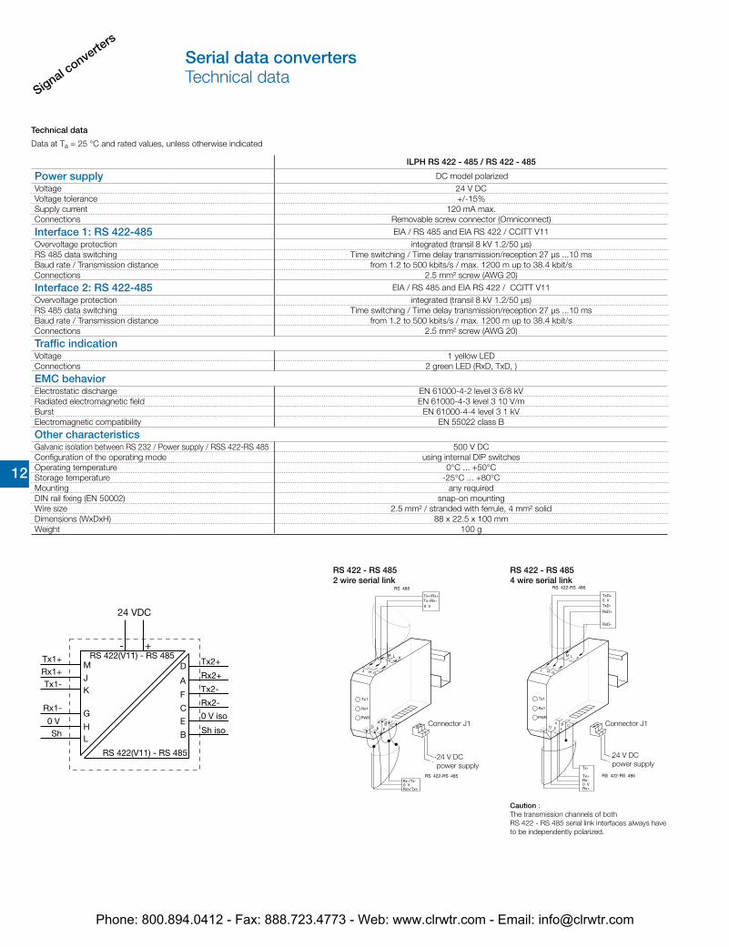
ILPH RS 422 - 485 / RS 422 - 485
Power supply DC model polarizedVoltage 24 V DCVoltage tolerance +/-15%Supply current 120 mA max.Connections Removable screw connector (Omniconnect)
Interface 1: RS 422-485 EIA / RS 485 and EIA RS 422 / CCITT V11Overvoltage protection integrated (transil 8 kV 1.2/50 µs)RS 485 data switching Time switching / Time delay transmission/reception 27 µs ...10 msBaud rate / Transmission distance from 1.2 to 500 kbits/s / max. 1200 m up to 38.4 kbit/sConnections 2.5 mm² screw (AWG 20)
Interface 2: RS 422-485 EIA / RS 485 and EIA RS 422 / CCITT V11Overvoltage protection integrated (transil 8 kV 1.2/50 µs)RS 485 data switching Time switching / Time delay transmission/reception 27 µs ...10 msBaud rate / Transmission distance from 1.2 to 500 kbits/s / max. 1200 m up to 38.4 kbit/sConnections 2.5 mm² screw (AWG 20)
Traffic indicationVoltage 1 yellow LEDConnections 2 green LED (RxD, TxD, )
EMC behaviorElectrostatic discharge EN 61000-4-2 level 3 6/8 kVRadiated electromagnetic field EN 61000-4-3 level 3 10 V/mBurst EN 61000-4-4 level 3 1 kVElectromagnetic compatibility EN 55022 class B
Other characteristicsGalvanic isolation between RS 232 / Power supply / RSS 422-RS 485 500 V DCConfiguration of the operating mode using internal DIP switchesOperating temperature 0°C ... +50°CStorage temperature -25°C ... +80°CMounting any requiredDIN rail fixing (EN 50002) snap-on mountingWire size 2.5 mm² / stranded with ferrule, 4 mm² solidDimensions (WxDxH) 88 x 22.5 x 100 mmWeight 100 g
Caution : The transmission channels of both RS 422 - RS 485 serial link interfaces always have to be independently polarized.
RS 422 - RS 4854 wire serial link
24 V DCpower supply
Connector J1
RS 422 - RS 4852 wire serial link
24 V DCpower supply
Connector J1
Serial data convertersTechnical data
Phone: 800.894.0412 - Fax: 888.723.4773 - Web: www.clrwtr.com - Email: [email protected]
Signal converters
12 12
Technical data
Data at Ta = 25 °C and rated values, unless otherwise indicated
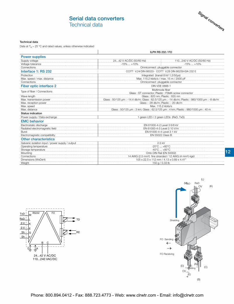
ILPH RS 232 / FO
Power suppliesSupply voltage 24...42 V AC/DC (50/60 Hz) 110...240 V AC/DC (50/60 Hz)Voltage tolerance -15% ... +10% -15% ... +10%Connections Omniconnect pluggable connector
Interface 1: RS 232 CCITT V.24/DIN 66020- CCITT V.28 DIN 66259-EIA 232 EProtection Integrated (transil 8 kV 1.2/50µs)Max. speed / max. distance Max. 115.2 kbits/s / max. 15 m / 2500 pFConnections Omniconnect pluggable connector
Fiber optic interface 2 DIN VDE 0888-1
Type of fiber / ConnectionsMultimode fiber
Glass : ST connector; Plastic : FSMA screw connectorWave length Glass : 820 nm; Plastic : 655 nmMax. transmission power Glass : 50/125 µm : -14.4 db/m; Glass : 62.5/125 µm : -14 db/m; Plastic : 980/1000 µm : -8 db/mMax. reception power Glass : -28 db/m; Plastic : -20 db/mMax. speed Max. 115.2 kbits/sMax. distance Glass : 50/125 µm : 3 km; Glass : 62.5/125 µm : 4 km; Plastic : 980/1000 µm : 40 mStatus indicationPower supply / Data exchange 1 green LED / 2 green LEDs (RxD, TxD)
EMC behaviorElectrostatic discharge EN 61000-4-2 Level 3 6/8 kVRadiated electromagnetic field EN 61000-4-3 Level 3 10 V/mBurst EN 61000-4-4 Level 3 1 kVElectromagnetic compatibility EN 55022 Class B
Other characteristicsGalvanic isolation input / power supply / output 2.5 kVOperating temperature -20°C ... +60°CStorage temperature -40°C ... +85°CMounting Onto DIN Rail (EN 50002)Connections 14 AWG (2.5 mm²) fine stranded / 12 AWG (4 mm²) rigidDimensions (WxDxH) 105 x 22.5 x 112 mm / 4.13 x 0.89 x 4.41"Weight 150 g / 0.33 lb
RxDOV
TxD
OV
←→
~+
~-
(L)
(K)(M)
(J H G)
(E)
(F)(D)
(B)
(C)(A)
Shielding
FO Sending
FO Receiving
Shielding
Serial data convertersTechnical data
Phone: 800.894.0412 - Fax: 888.723.4773 - Web: www.clrwtr.com - Email: [email protected]
Signal converte
rs
12 12
Technical data
Data at Ta = 25 °C and rated values, unless otherwise indicated
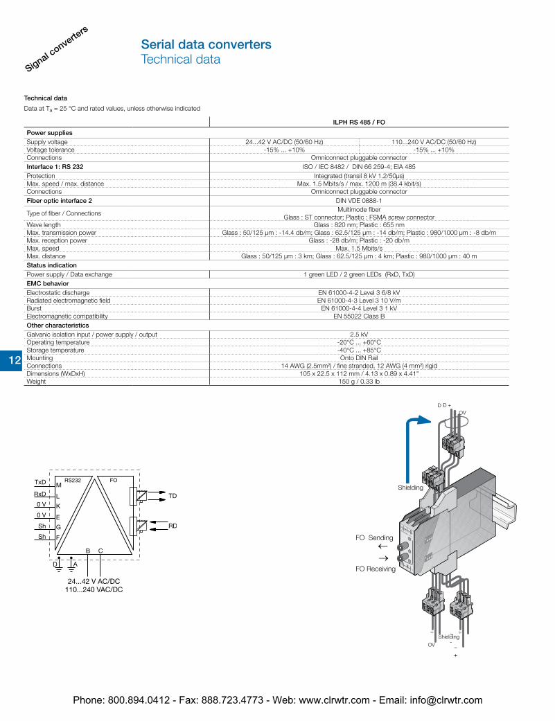
ILPH RS 485 / FO
Power suppliesSupply voltage 24...42 V AC/DC (50/60 Hz) 110...240 V AC/DC (50/60 Hz)Voltage tolerance -15% ... +10% -15% ... +10%Connections Omniconnect pluggable connectorInterface 1: RS 232 ISO / IEC 8482 / DIN 66 259-4; EIA 485Protection Integrated (transil 8 kV 1.2/50µs)Max. speed / max. distance Max. 1.5 Mbits/s / max. 1200 m (38.4 kbit/s)Connections Omniconnect pluggable connectorFiber optic interface 2 DIN VDE 0888-1
Type of fiber / ConnectionsMultimode fiber
Glass : ST connector; Plastic : FSMA screw connectorWave length Glass : 820 nm; Plastic : 655 nmMax. transmission power Glass : 50/125 µm : -14.4 db/m; Glass : 62.5/125 µm : -14 db/m; Plastic : 980/1000 µm : -8 db/mMax. reception power Glass : -28 db/m; Plastic : -20 db/mMax. speed Max. 1.5 Mbits/sMax. distance Glass : 50/125 µm : 3 km; Glass : 62.5/125 µm : 4 km; Plastic : 980/1000 µm : 40 mStatus indicationPower supply / Data exchange 1 green LED / 2 green LEDs (RxD, TxD)EMC behaviorElectrostatic discharge EN 61000-4-2 Level 3 6/8 kVRadiated electromagnetic field EN 61000-4-3 Level 3 10 V/mBurst EN 61000-4-4 Level 3 1 kVElectromagnetic compatibility EN 55022 Class BOther characteristicsGalvanic isolation input / power supply / output 2.5 kVOperating temperature -20°C ... +60°CStorage temperature -40°C ... +85°CMounting Onto DIN RailConnections 14 AWG (2.5mm²) / fine stranded, 12 AWG (4 mm²) rigidDimensions (WxDxH) 105 x 22.5 x 112 mm / 4.13 x 0.89 x 4.41"Weight 150 g / 0.33 lb
OVD -D +
←
←
Shielding
FO Sending
FO Receiving
OV
~-
~+
Shielding
Serial data convertersTechnical data
Phone: 800.894.0412 - Fax: 888.723.4773 - Web: www.clrwtr.com - Email: [email protected]
Signal converters
12 12
Technical data
Data at Ta = 25 °C and rated values, unless otherwise indicated
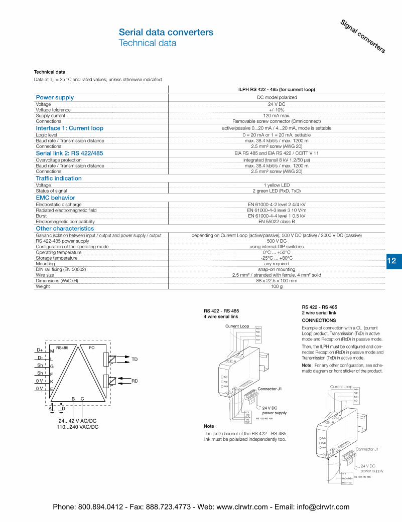
ILPH RS 422 - 485 (for current loop)
Power supply DC model polarizedVoltage 24 V DCVoltage tolerance +/-10%Supply current 120 mA max.Connections Removable screw connector (Omniconnect)
Interface 1: Current loop active/passive 0...20 mA / 4...20 mA, mode is settableLogic level 0 = 20 mA or 1 = 20 mA, settableBaud rate / Transmission distance max. 38.4 kbit/s / max. 1200 mConnections 2.5 mm² screw (AWG 20)
Serial link 2: RS 422/485 EIA RS 485 and EIA RS 422 / CCITT V 11Overvoltage protection integrated (transil 8 kV 1.2/50 µs)Baud rate / Transmission distance max. 38.4 kbit/s / max. 1200 mConnections 2.5 mm² screw (AWG 20)
Traffic indicationVoltage 1 yellow LEDStatus of signal 2 green LED (RxD, TxD)
EMC behaviorElectrostatic discharge EN 61000-4-2 level 2 4/4 kVRadiated electromagnetic field EN 61000-4-3 level 3 10 V/mBurst EN 61000-4-4 level 1 0.5 kVElectromagnetic compatibility EN 55022 class B
Other characteristicsGalvanic isolation between input / output and power supply / output depending on Current Loop (active/passive); 500 V DC (active) / 2000 V DC (passive)RS 422-485 power supply 500 V DCConfiguration of the operating mode using internal DIP switchesOperating temperature 0°C ... +50°CStorage temperature -25°C ... +80°CMounting any requiredDIN rail fixing (EN 50002) snap-on mountingWire size 2.5 mm² / stranded with ferrule, 4 mm² solidDimensions (WxDxH) 88 x 22.5 x 100 mmWeight 100 g
RS 422 - RS 4852 wire serial link
CONNECTIONS
Example of connection with a CL (current Loop) product, Transmission (TxD) in active mode and Reception (RxD) in passive mode.
Then, the ILPH must be configured and con-nected Reception (RxD) in passive mode and Transmission (TxD) in active mode.
Note : For any other configuration, see sche-matic diagram or front sticker of the product.
Current Loop
Connector J1
24 V DCpower supply
Note :
The TxD channel of the RS 422 - RS 485 link must be polarized independently too.
RS 422 - RS 4854 wire serial link
Current Loop
Connector J1
24 V DCpower supply
Serial data convertersTechnical data
Phone: 800.894.0412 - Fax: 888.723.4773 - Web: www.clrwtr.com - Email: [email protected]
Signal converte
rs
12 12
Technical data
Data at Ta = 25 °C and rated values, unless otherwise indicated
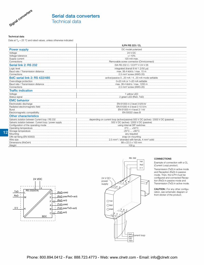
ILPH RS 223 / CL
Power supply DC model polarizedVoltage 24 V DCVoltage tolerance +/-10%Supply current 120 mA max.Connections Removable screw connector (Omniconnect)
Serial link 2: RS 232 EIA RS 232 C / CCITT V 24 V 28Logic level integrated (transil 8 kV 1.2/50 µs)Baud rate / Transmission distance max. 38.4 kbit/s / max. 15 mConnections 2.5 mm² screw (AWG 20)
BdC serial link 2: RS 422/485 active/passive 0...20 mA / 4...20 mA mode settableOvervoltage protection 0=20 mA or 1=20 mA settableBaud rate / Transmission distance max. 38.4 kbit/s / max. 1200 mConnections 2.5 mm² screw (AWG 20)
Traffic indicationVoltage 1 yellow LEDStatus signal 2 green LED (RxD, TxD)
EMC behaviorElectrostatic discharge EN 61000-4-2 level 3 6/8 kVRadiated electromagnetic field EN 61000-4-3 level 3 10 V/mBurst EN 61000-4-4 level 3 1 kVElectromagnetic compatibility EN 55022 class B
Other characteristicsGalvanic isolation between Current loop / RS 232 depending on current loop (active/passive) 500 V DC (active) / 2000 V DC (passive)Galvanic isolation between Current loop / power supply 500 V DC (active) / 2000 V DC (passive)Configuration of the operating mode using internal DIP switchesOperating temperature 0°C ... +50°CStorage temperature -25°C ... +80°CMounting any requiredDIN rail fixing (EN 50002) snap-on mountingWire size 2.5 mm² / stranded with ferrule, 4 mm² solidDimensions (WxDxH) 88 x 22.5 x 100 mmWeight 100 g
Current loop
24 V DCpower supply
CONNECTIONS
Example of connection with a CL (Current Loop) product,
Transmission (TxD) in active mode and Reception (RxD) in passive mode. Then, the ILPH must be configured and connected Recep-tion (RxD) in passive mode and Transmission (TxD) in active mode.
CAUTION : For any other configu-ration, see schematic diagram or front sticker of the product.
Serial data convertersTechnical data
Phone: 800.894.0412 - Fax: 888.723.4773 - Web: www.clrwtr.com - Email: [email protected]


![ABB Serial Data Converters[1]](https://img.dokumen.tips/doc/110x75/5525aded550346a26e8b4a20/abb-serial-data-converters1.jpg)