Embed Size (px)
DESCRIPTION
ABB Prot relay
Citation preview
Relion 615® series
Feeder protection and controlREF615 ANSIProduct guide
ABB 2
1MAC105361-PG Rev. E
Issued: 04.15.2011
Feeder Protection
REF615 ANSI
Product Version 4.0
Contents
Disclaimer
Th e information in this document is subject to change without notice and should not be construed as a commitment by ABB Inc. ABB Inc. assumes no responsibility for any errors that may appear in this document.
Copyright © 2008-2011 ABB
All rights reserved.
Trademarks
ABB is a registered trademark of ABB Group. All other brand or product names mentioned in this document may be trademarks or registered trademarks of their respective holders.
1 Description . . . . . . . . . . . . . . . . . . . . . . . . . . . . . 3
2 Standard confi gurations . . . . . . . . . . . . . . . . 4 - 5
3 Protection functions . . . . . . . . . . . . . . . . . . . 6 - 8
4 Application . . . . . . . . . . . . . . . . . . . . . . . . . 9 - 13
5 Supported ABB solutions . . . . . . . . . . . . . 14 - 15
6 Control . . . . . . . . . . . . . . . . . . . . . . . . . . . . . . . 16
7 Measurement . . . . . . . . . . . . . . . . . . . . . . . . . . 16
8 Digital fault recorder . . . . . . . . . . . . . . . . . . . . . 16
9 Events recorder . . . . . . . . . . . . . . . . . . . . . . . . 16
10 Fault recorder . . . . . . . . . . . . . . . . . . . . . . . . . 17
11 Circuit-breaker monitoring . . . . . . . . . . . . . . . 17
12 Trip-circuit supervision . . . . . . . . . . . . . . . . . . 17
13 Self-diagnostics . . . . . . . . . . . . . . . . . . . . . . . 17
14 Fuse failure protection . . . . . . . . . . . . . . . . . . 18
15 Current circuit supervision . . . . . . . . . . . . . . . 18
16 Load profi le recording . . . . . . . . . . . . . . . . . . 18
17 Power quality . . . . . . . . . . . . . . . . . . . . . . . . . 18
18 Single-line diagram (SLD) . . . . . . . . . . . . . . . . 18
19 Cable fault detection (CFD) . . . . . . . . . . . . . . 19
20 Access control . . . . . . . . . . . . . . . . . . . . . . . . 19
21 Inputs and outputs . . . . . . . . . . . . . . . . . . 19-20
22 Communication . . . . . . . . . . . . . . . . . . . . 21-22
23 Technical data . . . . . . . . . . . . . . . . . . . . 23 - 51
24 Display options . . . . . . . . . . . . . . . . . . . . . . . . 52
25 Mounting methods . . . . . . . . . . . . . . . . . . . . . 53
26 Relay case and relay plug-in unit . . . . . . . . . . 53
27 Selection and ordering data . . . . . . . . . . . 54-55
28 Accessories and ordering data. . . . . . . . . . . . 56
29 Tools . . . . . . . . . . . . . . . . . . . . . . . . . . . . . . . . 57
30 Terminal diagrams . . . . . . . . . . . . . . . . . 58 - 62
31 Certifi cates . . . . . . . . . . . . . . . . . . . . . . . . . . . 63
32 References . . . . . . . . . . . . . . . . . . . . . . . . . . . 63
33 Functions, codes and symbols . . . . . . . 64 - 66
34 Document revision history . . . . . . . . . . . . . . . 67
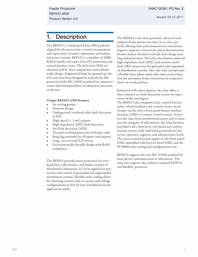
ABB 3
Feeder Protection
REF615 ANSI
Product Version 4.0
1MAC105361-PG Rev. E
Issued: 04.15.2011
1. DescriptionThe REF615 is a dedicated feeder IED perfectly aligned for the protection, control, measurement and supervision of utility substations and indust-rial power systems. REF615 is a member of ABB’s Relion® family and a part of its 615 protection and control product series. The 615 series IEDs are characterized by their compactness and withdra-wable design. Engineered from the ground up, the 615 series has been designed to unleash the full potential of the IEC 61850 standard for communi-cation and interoperability of substation automati-on devices.
Unique REF615 ANSI features• Six setting groups• Drawout design• Underground, overhead cable fault detection
(CFD)• High-speed (< 1 ms) outputs• High impedance (HIZ) fault detection• Arc flash detection (AFD)• Thermal overload protection of feeder cable• Ring-lug terminals for all inputs and outputs• Large, easy to read LCD screen• Environmentally friendly design with RoHS
compliance
The REF615 provides main protection for over-head lines, cable feeders, and busbar systems of distribution substations. It can be applied for pro-tection and control of grounded and ungrounded distribution systems. Flexible order coding allows for choosing current-only or current-and-voltage configurations to best fit your distribution feeder application needs.
The REF615 is the most powerful, advanced and simplest feeder protection relay in its class, per-fectly offering time and instantaneous overcurrent, negative sequence overcurrent, phase discontinuity, breaker failure, thermal overload, and voltage mete-ring and protection. The relay also features optional high impedance fault (HIZ) and sensitive earth fault (SEF) protection for grounded and unground-ed distribution systems. Also, the relay incorporates a flexible three-phase multi-shot auto-reclose func-tion for automatic feeder restoration in temporary faults on overhead lines.
Enhanced with safety options, the relay offers a three-channel arc-fault detection system for super-vision of the switchgear.The REF615 also integrates basic control functio-nality, which facilitates the control of one circuit breaker via the relay’s front panel human machine interface (HMI) or remote control system. To pro-tect the relay from unauthorized access and to main-tain the integrity of information, the relay has been provided with a four-level, role-based user authen-tication system, with individual passwords for the viewer, operator, engineer, and administrator levels. The access control system applies to the front panel HMI, embedded web browser based HMI, and the PCM600 relay setting and configuration tool.
REF615 supports the new IEC 61850 standard for inter-device communication in substations. The relay also supports the industry standard DNP3.0 and Modbus® protocols.
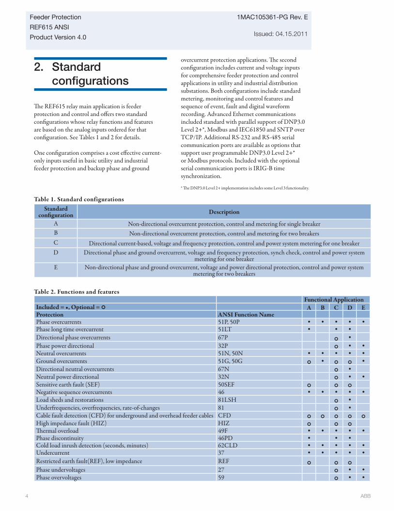
ABB 4
1MAC105361-PG Rev. E
Issued: 04.15.2011
Feeder Protection
REF615 ANSI
Product Version 4.0
2. Standard confi gurations
Th e REF615 relay main application is feeder protection and control and off ers two standard confi gurations whose relay functions and features are based on the analog inputs ordered for that confi guration. See Tables 1 and 2 for details.
One confi guration comprises a cost eff ective current-only inputs useful in basic utility and industrial feeder protection and backup phase and ground
Table 1. Standard configurationsStandard
confi guration Description
A Non-directional overcurrent protection, control and metering for single breakerB Non-directional overcurrent protection, control and metering for two breakers C Directional current-based, voltage and frequency protection, control and power system metering for one breakerD Directional phase and ground overcurrent, voltage and frequency protection, synch check, control and power system
metering for one breakerE Non-directional phase and ground overcurrent, voltage and power directional protection, control and power system
metering for two breakers
overcurrent protection applications. Th e second confi guration includes current and voltage inputs for comprehensive feeder protection and control applications in utility and industrial distribution substations. Both confi gurations include standard metering, monitoring and control features and sequence of event, fault and digital waveform recording. Advanced Ethernet communications included standard with parallel support of DNP3.0 Level 2+*, Modbus and IEC61850 and SNTP over TCP/IP. Additional RS-232 and RS-485 serial communication ports are available as options that support user programmable DNP3.0 Level 2+* or Modbus protocols. Included with the optional serial communication ports is IRIG-B time synchronization.
* Th e DNP3.0 Level 2+ implementation includes some Level 3 functionality.
Functional ApplicationIncluded = •, Optional = A B C D EProtection ANSI Function NamePhase overcurrents 51P, 50P • • • • •Phase long time overcurrent 51LT • • •Directional phase overcurrents 67P •Phase power directional 32P • •Neutral overcurrents 51N, 50N • • • • •Ground overcurrents 51G, 50G • •Directional neutral overcurrents 67N •Neutral power directional 32N • •Sensitive earth fault (SEF) 50SEF
Negative sequence overcurrents 46 • • • • •Load sheds and restorations 81LSH •Underfrequencies, overfrequencies, rate-of-changes 81 •Cable fault detection (CFD) for underground and overhead feeder cables CFD
High impedance fault (HIZ) HIZ
Th ermal overload 49F • • • • •Phase discontinuity 46PD • • •Cold load inrush detection (seconds, minutes) 62CLD • • • • •Undercurrent 37 • • • • •Restricted earth fault(REF), low impedance REF
Phase undervoltages 27 • •Phase overvoltages 59 • •
Table 2. Functions and features
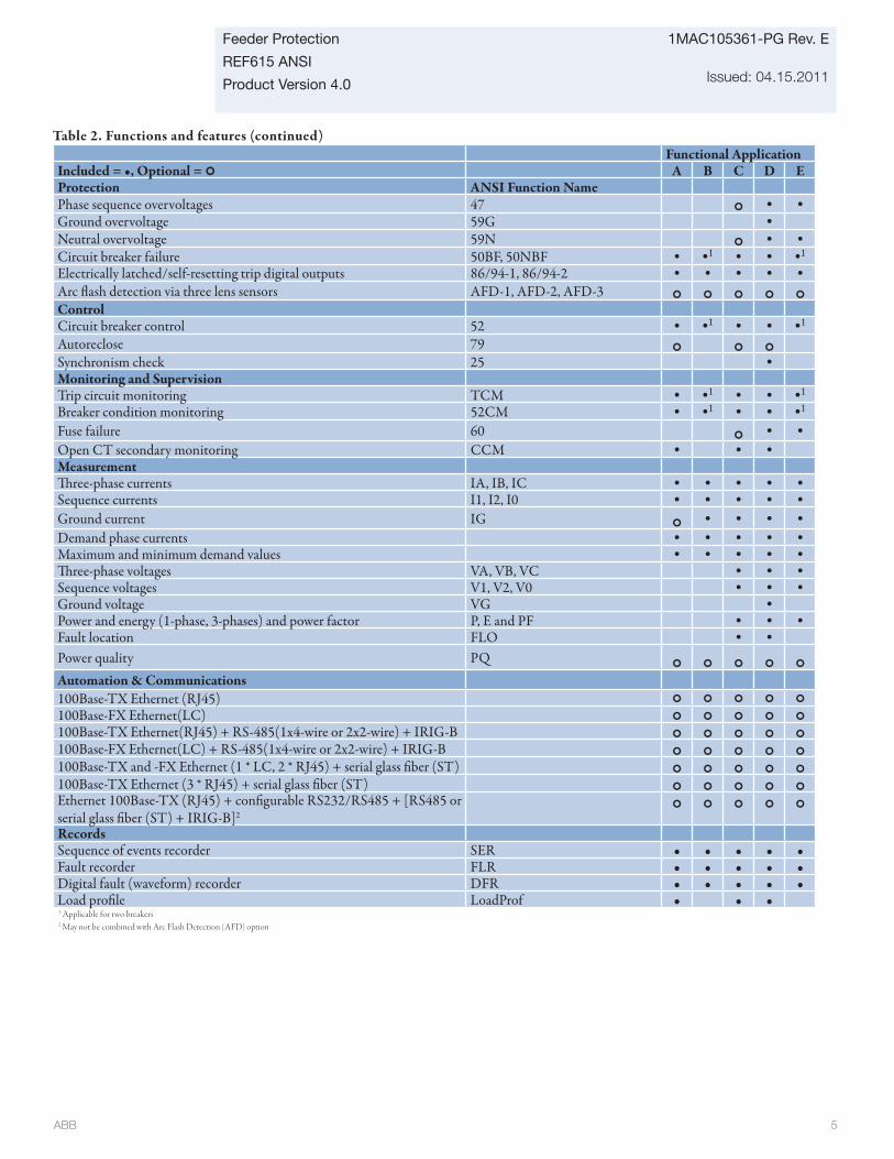
ABB 5
Feeder Protection
REF615 ANSI
Product Version 4.0
1MAC105361-PG Rev. E
Issued: 04.15.2011
Table 2. Functions and features (continued)Functional Application
Included = •, Optional = A B C D EProtection ANSI Function NamePhase sequence overvoltages 47 • •Ground overvoltage 59G •Neutral overvoltage 59N • •Circuit breaker failure 50BF, 50NBF • •1 • • •1
Electrically latched/self-resetting trip digital outputs 86/94-1, 86/94-2 • • • • •Arc fl ash detection via three lens sensors AFD-1, AFD-2, AFD-3
ControlCircuit breaker control 52 • •1 • • •1
Autoreclose 79
Synchronism check 25 •Monitoring and SupervisionTrip circuit monitoring TCM • •1 • • •1
Breaker condition monitoring 52CM • •1 • • •1
Fuse failure 60 • •Open CT secondary monitoring CCM • • •MeasurementTh ree-phase currents IA, IB, IC • • • • •Sequence currents I1, I2, I0 • • • • •Ground current IG • • • •Demand phase currents • • • • •Maximum and minimum demand values • • • • •Th ree-phase voltages VA, VB, VC • • •Sequence voltages V1, V2, V0 • • •Ground voltage VG •Power and energy (1-phase, 3-phases) and power factor P, E and PF • • •Fault location FLO • •Power quality PQ
Automation & Communications100Base-TX Ethernet (RJ45)
100Base-FX Ethernet(LC)
100Base-TX Ethernet(RJ45) + RS-485(1x4-wire or 2x2-wire) + IRIG-B
100Base-FX Ethernet(LC) + RS-485(1x4-wire or 2x2-wire) + IRIG-B
100Base-TX and -FX Ethernet (1 * LC, 2 * RJ45) + serial glass fi ber (ST)
100Base-TX Ethernet (3 * RJ45) + serial glass fi ber (ST) Ethernet 100Base-TX (RJ45) + confi gurable RS232/RS485 + [RS485 or serial glass fi ber (ST) + IRIG-B]2
RecordsSequence of events recorder SER • • • • •Fault recorder FLR • • • • •Digital fault (waveform) recorder DFR • • • • •Load profi le LoadProf • • •1 Applicable for two breakers2 May not be combined with Arc Flash Detection (AFD) option
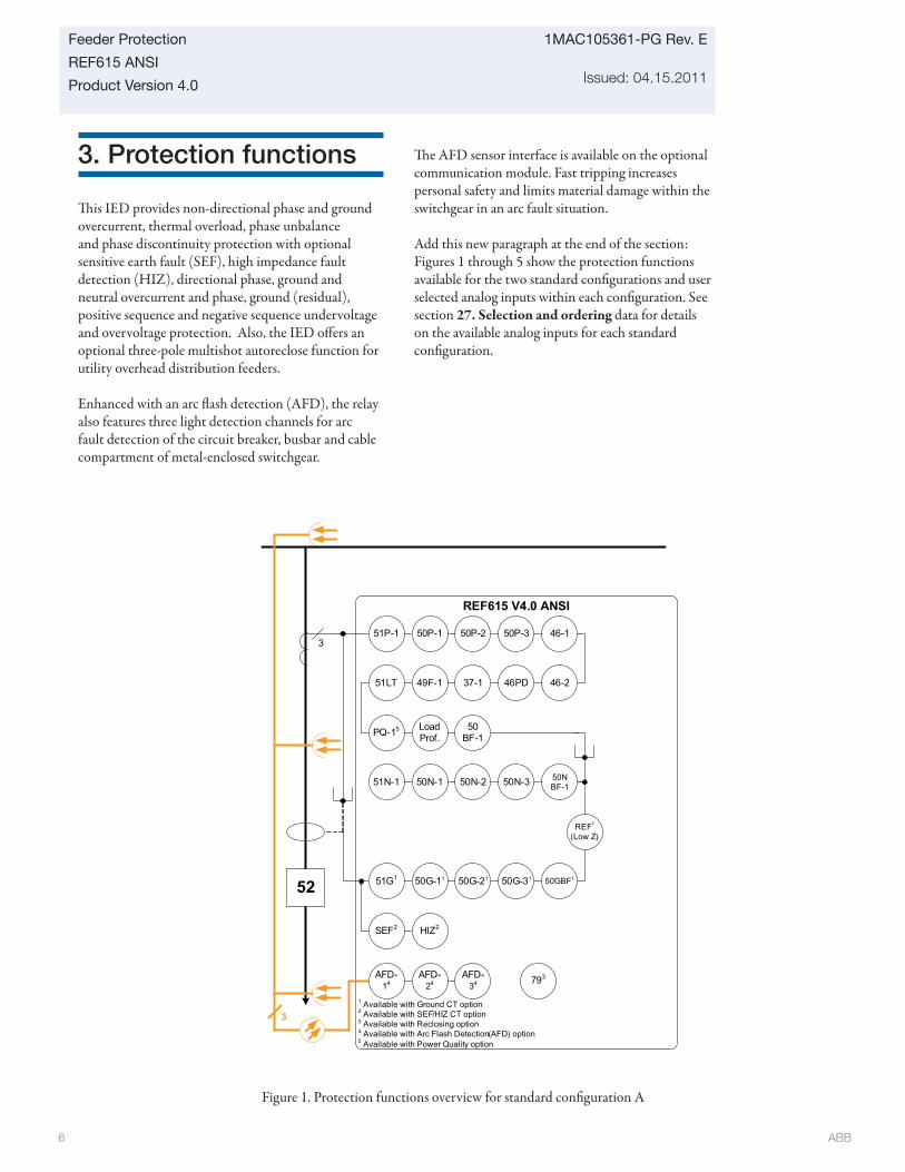
ABB 6
1MAC105361-PG Rev. E
Issued: 04.15.2011
Feeder Protection
REF615 ANSI
Product Version 4.0
Figure 1. Protection functions overview for standard confi guration A
3
793
51P-1 50P-1 50P-3
46PD37-149F-1
51G1
REF615 V4.0 ANSI
1 Available with Ground CT option2 Available with SEF/HIZ CT option3 Available with Reclosing option4 Available with Arc Flash Detection(AFD) option5 Available with Power Quality option
3
52
AFD-34
AFD-14
AFD-24
50N-1
51LT
51N-1
SEF2
50P-2
46-2
50N-2 50N-3
46-1
50G-31
50BF-1
50NBF-1
50GBF1
REF1
(Low Z)
LoadProf.PQ-15
HIZ2
50G-2150G-11
3. Protection functions
Th is IED provides non-directional phase and ground overcurrent, thermal overload, phase unbalance and phase discontinuity protection with optional sensitive earth fault (SEF), high impedance fault detection (HIZ), directional phase, ground and neutral overcurrent and phase, ground (residual), positive sequence and negative sequence undervoltage and overvoltage protection. Also, the IED off ers an optional three-pole multishot autoreclose function for utility overhead distribution feeders.
Enhanced with an arc fl ash detection (AFD), the relay also features three light detection channels for arc fault detection of the circuit breaker, busbar and cable compartment of metal-enclosed switchgear.
Th e AFD sensor interface is available on the optional communication module. Fast tripping increases personal safety and limits material damage within the switchgear in an arc fault situation.
Add this new paragraph at the end of the section: Figures 1 through 5 show the protection functions available for the two standard confi gurations and user selected analog inputs within each confi guration. See section 27. Selection and ordering data for details on the available analog inputs for each standard confi guration.
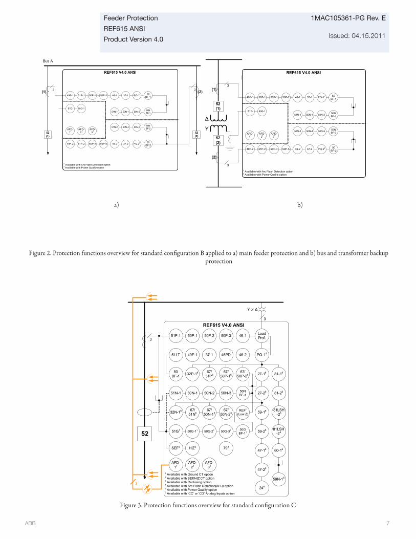
ABB 7
Feeder Protection
REF615 ANSI
Product Version 4.0
1MAC105361-PG Rev. E
Issued: 04.15.2011
Figure 3. Protection functions overview for standard confi guration C
3
793HIZ2
46PD37-149F-1
50G-1151G1
1 Available with Ground CT option2 Available with SEF/HIZ CT option3 Available with Reclosing option4 Available with Arc Flash Detection(AFD) option5 Available with Power Quality option6 Available with ‘CC’ or ‘CD’ Analog Inputs option
3
52
AFD-34
AFD-14
AFD-24
3
Υ or Δ
27-26
27-16
59-16
59-26
47-16
50N-1
51LT
51N-1
SEF2
47-26
81-16
81-26
81LSH-26
81LSH-26
46-2
50N-2 50N-3
50G-21 50G-31
67/51P6
67/50P-16
67/50P-2632P-1650
BF-1
67/50N-2632N-16 67/
51N667/
50N-16
50NBF-1
50GBF-11
REF1
(Low Z)
PQ-15
51P-1 50P-1 50P-3
REF615 V4.0 ANSI
50P-2 46-1 LoadProf.
59N-16
60-16
246
Figure 2. Protection functions overview for standard confi guration B applied to a) main feeder protection and b) bus and transformer backup protection
37-146-150P-149F-1 51P-1 50P-2
51N-1 50N-2
AFD-11
AFD-21
AFD-31
Bus A
52 (1)
52 (2)
REF615 V4.0 ANSI
50N-1
3 3
37-246-250P-449F-2 51P-2 50P-5
50N-4 50N-551N-2
50G-151G
1 Available with Arc Flash Detection option2 Available with Power Quality option
(1) (2)PQ-12
PQ-22
50N BF-1
50BF-1
50BF-2
50N BF-2
37-146-150P-149F-1 51P-1 50P-2
51N-1 50N-2
AFD-11
AFD-21
AFD-31
REF615 V4.0 ANSI
50N-1
50N-4 50N-551N-2
50G-151G
PQ-12
50NBF-1
50BF-1
50NBF-2
52 (1)
Δ
Y
3
3
52 (2)
37-246-250P-449F-2 51P-2 50P-5 PQ-22 50BF-2
(1)
(2)
1 Available with Arc Flash Detection option2 Available with Power Quality option
a) b)
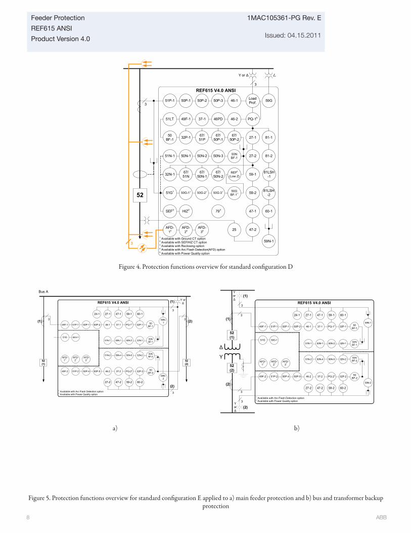
ABB 8
1MAC105361-PG Rev. E
Issued: 04.15.2011
Feeder Protection
REF615 ANSI
Product Version 4.0
37-146-150P-149F-1 50BF-151P-1 50P-2
51N-1 50N-2 50NBF-1
AFD-11
AFD-21
AFD-31
Bus A
52 (1)
52 (2)
REF615 V4.0 ANSI
50N-1
3 3
37-246-250P-449F-2 50BF-251P-2 50P-5
50N-4 50N-5 50NBF-251N-2
50G-151G
(1) (2)PQ-12
PQ-22
27-1 47-1
59N-1
24-13
Υ or Δ
27-2 47-2
59N-2
3
(1)
(2)
32N-1
32P-1
32P-2
32N-2
60-2
60-159-1
59-2
1 Available with Arc Flash Detection option2 Available with Power Quality option
37-146-150P-149F-1 50BF-151P-1 50P-2
51N-1 50N-2 50NBF-1
AFD-11
AFD-21
AFD-31
50N-1
50N-4 50N-5 50NBF-251N-2
50G-151G
PQ-12
27-1 47-1
59N-1
24-1
27-2 47-2
59N-2
32N-1
32P-1
32N-2
60-2
60-1
52 (1)
Δ
Y
3
3Υor Δ
3
3
Υor Δ
52 (2)
37-246-250P-449F-2 50BF-251P-2 50P-5 PQ-22 32P-2
(1)
(1)
(2)
(2)
REF615 V4.0 ANSI
59-1
59-2
1 Available with Arc Flash Detection option2 Available with Power Quality option
Figure 5. Protection functions overview for standard confi guration E applied to a) main feeder protection and b) bus and transformer backup protection
a) b)
3
793HIZ2
46PD37-149F-1
50G-1151G1
1 Available with Ground CT option2 Available with SEF/HIZ CT option3 Available with Reclosing option4 Available with Arc Flash Detection(AFD) option5 Available with Power Quality option
3
52
AFD-34
AFD-14
AFD-24
3
Υ or Δ
27-2
27-1
59-1
59-2
47-1
50N-1
51LT
51N-1
SEF2
47-2
81-1
81-2
81LSH-1
81LSH-2
46-2
50N-2 50N-3
50G-21 50G-31
67/51P
67/50P-1
67/50P-232P-150
BF-1
67/50N-232N-1 67/
51N67/
50N-1
50NBF-1
50GBF-11
REF1
(Low Z)
PQ-15
Δ
59G51P-1 50P-1 50P-3
REF615 V4.0 ANSI
50P-2 46-1 LoadProf.
59N-1
25
60-1
Figure 4. Protection functions overview for standard confi guration D
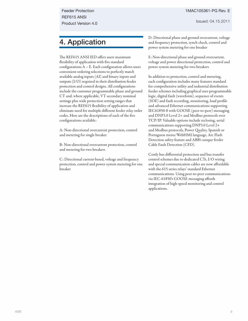
ABB 9
Feeder Protection
REF615 ANSI
Product Version 4.0
1MAC105361-PG Rev. E
Issued: 04.15.2011
4. Application
Th e REF615 ANSI IED off ers users maximum fl exibility of application with fi ve standard confi gurations A – E. Each confi guration allows users convenient ordering selections to perfectly match available analog inputs (AI) and binary inputs and outputs (I/O) required in their distribution feeder protection and control designs. All confi gurations include the customer programmable phase and ground CT and, where applicable, VT secondary nominal settings plus wide protection setting ranges that increase the REF615 fl exibility of application and eliminate need for multiple diff erent feeder relay order codes. Here are the descriptions of each of the fi ve confi gurations available:
A: Non-directional overcurrent protection, control and metering for single breaker
B: Non-directional overcurrent protection, control and metering for two breakers
C: Directional current-based, voltage and frequency protection, control and power system metering for one breaker
D: Directional phase and ground overcurrent, voltage and frequency protection, synch check, control and power system metering for one breaker
E: Non-directional phase and ground overcurrent, voltage and power directional protection, control and power system metering for two breakers
In addition to protection, control and metering, each confi guration includes many features standard for comprehensive utility and industrial distribution feeder schemes including graphical user-programmable logic, digital fault (waveform), sequence of events (SOE) and fault recording, monitoring, load profi le and advanced Ethernet communications supporting IEC61850-8 with GOOSE (peer-to-peer) messaging and DNP3.0 Level 2+ and Modbus protocols over TCP/IP. Valuable options include reclosing, serial communications supporting DNP3.0 Level 2+ and Modbus protocols, Power Quality, Spanish or Portuguese menu/WebHMI language, Arc Flash Detection safety feature and ABB’s unique feeder Cable Fault Detection (CFD).
Costly bus diff erential protection and bus transfer control schemes due to dedicated CTs, I/O wiring and special communication cables are now aff ordable with the 615 series relays’ standard Ethernet communications. Using peer-to-peer communications via IEC-61850’s GOOSE messaging aff ords integration of high-speed monitoring and control applications.
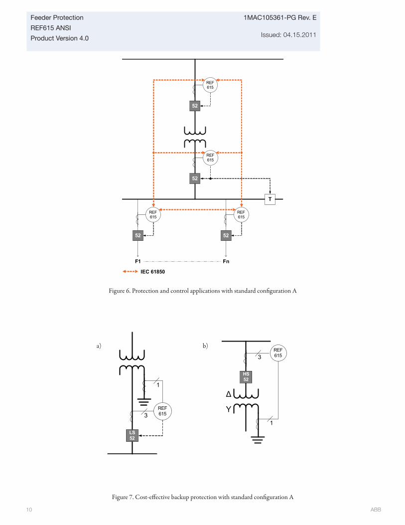
ABB 10
1MAC105361-PG Rev. E
Issued: 04.15.2011
Feeder Protection
REF615 ANSI
Product Version 4.0
Figure 7. Cost-eff ective backup protection with standard confi guration A
a) b)
3
1
LS52
REF615
REF615
HS52
3
1
Δ
Y
Figure 6. Protection and control applications with standard confi guration A
52
52
52
T
IEC 61850
F1 Fn
52
REF615
REF615
REF615
REF615
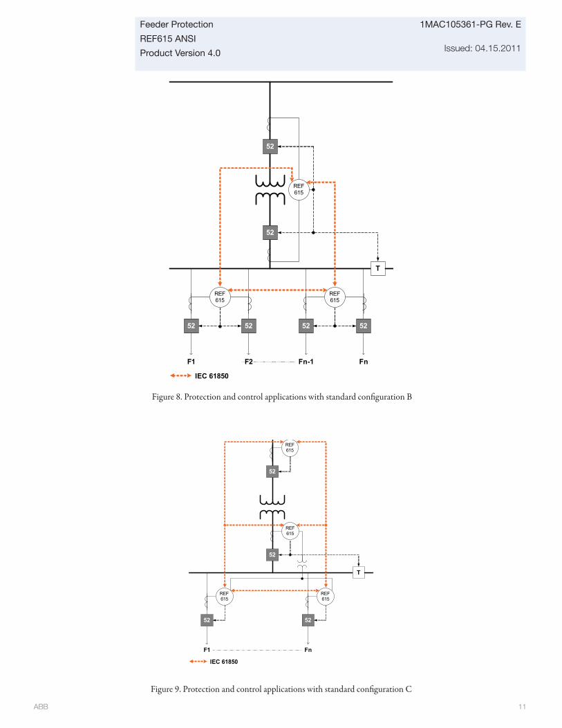
ABB 11
Feeder Protection
REF615 ANSI
Product Version 4.0
1MAC105361-PG Rev. E
Issued: 04.15.2011
Figure 8. Protection and control applications with standard confi guration B
Figure 9. Protection and control applications with standard confi guration C
52
52
52
T
IEC 61850
F1
REF615
52
F2
52
Fn-1
REF615
52
Fn
REF615
52
52
52
T
IEC 61850
F1 Fn
52
REF615
REF615
REF615
REF615
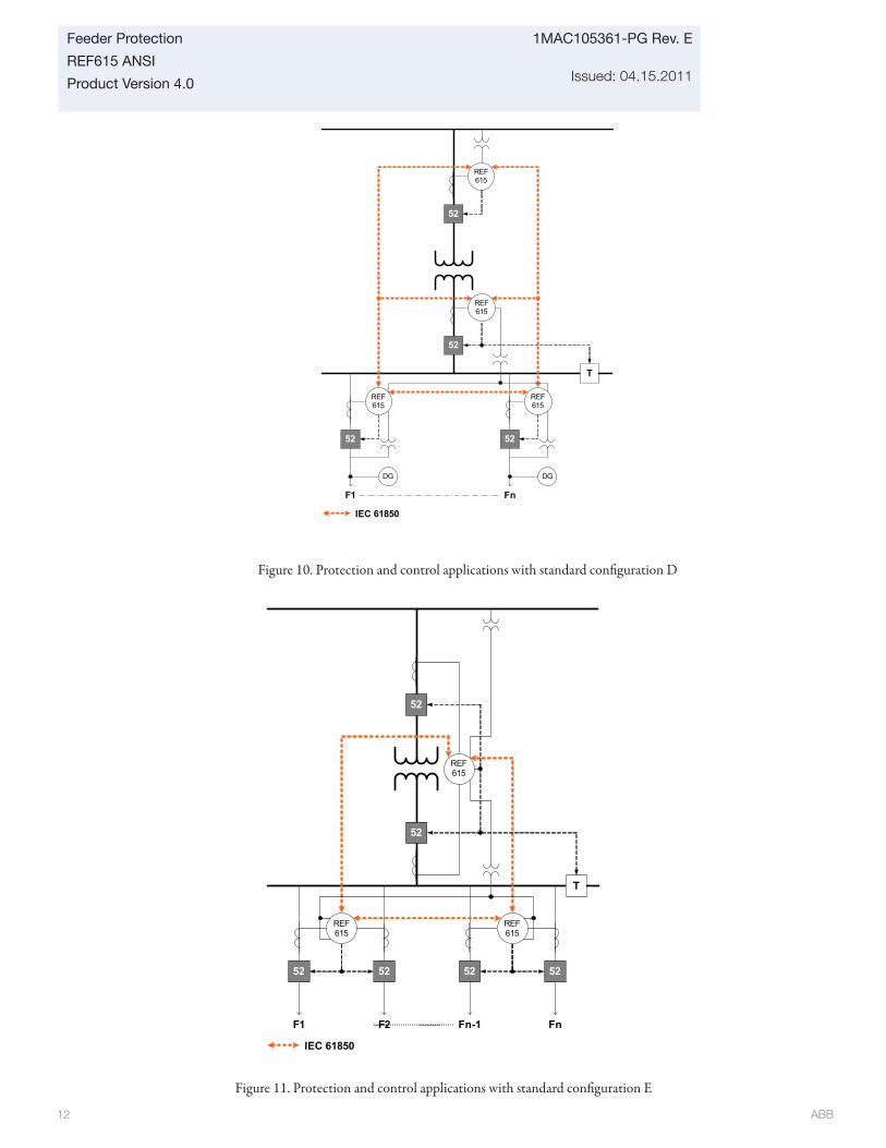
ABB 12
1MAC105361-PG Rev. E
Issued: 04.15.2011
Feeder Protection
REF615 ANSI
Product Version 4.0
52
52
52
T
IEC 61850
F1
REF615
52
F2
52
Fn-1
REF615
52
Fn
REF615
Figure 11. Protection and control applications with standard confi guration E
Figure 10. Protection and control applications with standard confi guration D
52
52
52
T
IEC 61850
F1 Fn
52
REF615
REF615
DGDG
REF615
REF615
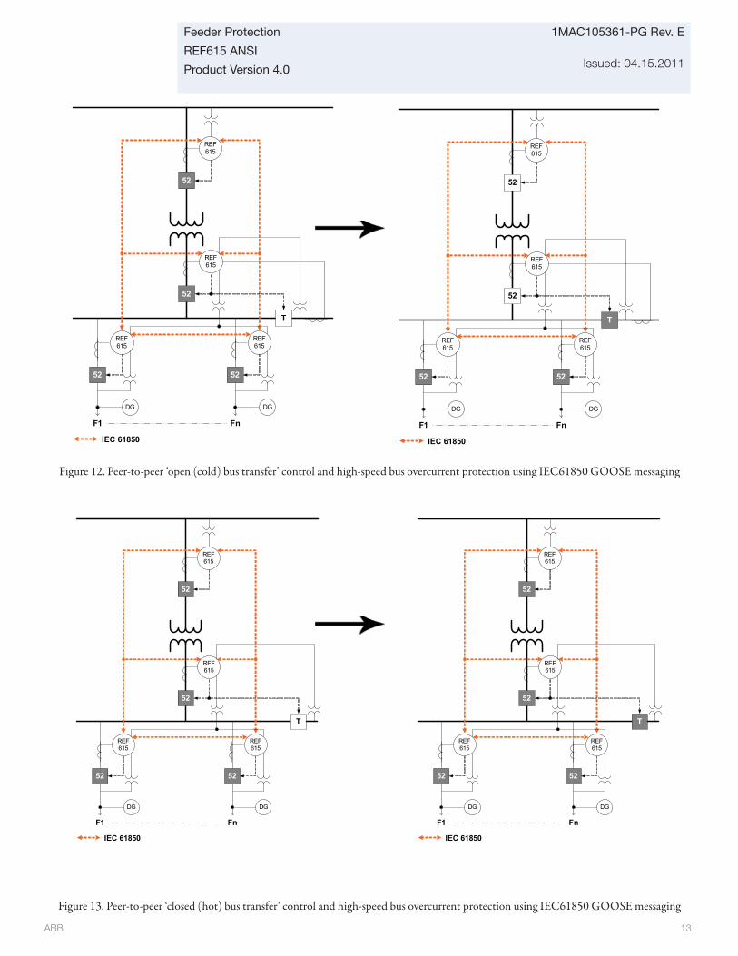
ABB 13
Feeder Protection
REF615 ANSI
Product Version 4.0
1MAC105361-PG Rev. E
Issued: 04.15.2011
Figure 13. Peer-to-peer ‘closed (hot) bus transfer’ control and high-speed bus overcurrent protection using IEC61850 GOOSE messaging
Figure 12. Peer-to-peer ‘open (cold) bus transfer’ control and high-speed bus overcurrent protection using IEC61850 GOOSE messaging
52
52
52
T
IEC 61850
F1 Fn
52
REF615
REF615
DGDG
REF615
REF615
52
52
52
T
IEC 61850
F1 Fn
52
REF615
REF615
DGDG
REF615
REF615
52
52
52
T
IEC 61850
F1 Fn
52
REF615
REF615
DGDG
REF615
REF615
52
52
52
T
IEC 61850
F1 Fn
52
REF615
REF615
DGDG
REF615
REF615
ABB 14
1MAC105361-PG Rev. E
Issued: 04.15.2011
Feeder Protection
REF615 ANSI
Product Version 4.0
5. Supported ABB solutions
ABB’s 615 series protection and control IEDs together with the COM600 Station Automation device constitute a genuine IEC 61850 solution for reliable power distribution in utility and industrial power systems. To facilitate and streamline the system engineering ABB’s IEDs are supplied with Connectivity Packages containing a compilation of soft ware and IED-specifi c information including single-line diagram templates, a full IED data model including event and parameter lists. By utilizing the Connectivity Packages the IEDs can be readily confi gured via the PCM600 Protection and Control IED Manager and integrated with the COM600 Station Automation device or the MicroSCADA Pro network control and management system.
Th e 615 series IEDs off er native support for the IEC 61850 standard also including horizontal GOOSE messaging. Compared with traditional hard-wired inter-device signaling, peer-to-peer communication over a switched Ethernet LAN off ers an advanced and versatile platform for power system protection. Fast soft ware-based communication, continuous supervision of the integrity of the protection and communication system, and inherent fl exibility for reconfi guration and upgrades are among the distinctive features of the protection system approach enabled by the full implementation of the IEC 61850 substation automation standard.
At the substation level COM600 utilizes the data content of the design level IEDs to off er enhanced substation level functionality. COM600 features a web-browser based HMI providing a customizable graphical display for visualizing single line mimic diagrams for switchgear design solutions. To enhance personnel safety, the web HMI also enables remote access to substation devices and processes. Furthermore, COM600 can be used as a local data warehouse for technical documentation of the substation and for network data collected by the IEDs. Th e collected network data facilitates extensive reporting and analyzing of network fault situations using the data historian and event handling features of COM600.
COM600 also features gateway functionality providing seamless connectivity between the substation IEDs and network-level control and management systems such as MicroSCADA Pro and System 800xA.
Table 3. Supported ABB solutions
Product VersionStation Automation COM600 3.4 or later
MicroSCADA Pro 9.3 or later
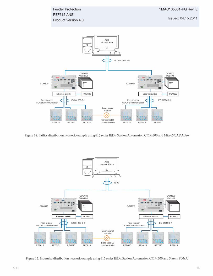
ABB 15
Feeder Protection
REF615 ANSI
Product Version 4.0
1MAC105361-PG Rev. E
Issued: 04.15.2011
COM600
Peer-to-peer GOOSE communication
Peer-to-peer GOOSE communication
IEC 61850-8-1 IEC 61850-8-1
Ethernet switch PCM600 PCM600
REM615REF615 RET615 RED615
Ethernet switch
RET615RED615 REM615 REF615Fibre optic LD communication
Binary signal transfer
OPC
COM600Web HMI
COM600Web HMI
COM600
Ethernet switch
ABB System 800xA
Peer-to-peer GOOSE communication
IEC 61850-8-1
IEC 60870-5-104
COM600Web HMI
ABBMicroSCADA
Ethernet switch PCM600
REF615RED615 RET615RET615REF615 RED615Fibre optic LD communication
Binary signal transfer
COM600
Peer-to-peer GOOSE communication
IEC 61850-8-1
COM600Web HMI
PCM600Ethernet switch
COM600
Figure 14. Utility distribution network example using 615 series IEDs, Station Automation COM600 and MicroSCADA Pro
Figure 15. Industrial distribution network example using 615 series IEDs, Station Automation COM600 and System 800xA
ABB 16
1MAC105361-PG Rev. E
Issued: 04.15.2011
Feeder Protection
REF615 ANSI
Product Version 4.0
6. Control
Th e relay off ers status and control of one or two breakers, depending on the standard confi guration selected, with a set of push-buttons on the front panel local human machine interface (LHMI) for opening and closing a breaker. Flexible remote breaker control of select-before-trip (SBO) or direct trip is also available with each of the supported DNP3.0 Level 2+, Modbus and IEC 61850 communication protocols. Interlocking schemes required by the application are confi gured with the signal matrix tool in PCM600 by the application are confi gured with the Signal Matrix Tool (SMT) of the REF615 user tool PCM600.
7. Measurements
Th e relay continuously measures the phase currents, the sequence components of the currents and the residual current. If the relay includes the ground ct option, it also measures the ground current, IG.
In addition, the relay calculates the demand and minimum and maximum demand currents over a user-selectable pre-set time frame, the thermal overload of the protected object, and the phase unbalance value as a ratio between the negative sequence and positive sequence currents. With VT inputs options, voltage, power and energy (single-phase and three-phase quantities), power factor and frequency measurements and minimum and maximum demand watts and vars are available.
Th e values measured can be accessed locally via the user interface on the relay front panel or remotely via the communication interface of the relay. Th e values can also be accessed locally or remotely using the web-browser based user interface.
8. Digital fault recorder
Th e relay is provided with a digital fault recorder (DFR) featuring up to four analog and 64 binary signal channels. Th e analog channels record either the waveform or the trend of the currents measured.
Th e analog channels can be set to trigger the recording function when the measured value falls below or exceeds the set values. Th e binary signal channels can be set to start a recording on the rising or the falling edge of the binary signal or both.
By default, the binary channels are set to record external or internal relay signals, e.g. the pickup or trip signals of the relay stages, or external blocking or control signals. Binary relay signals such as a protection pickup or trip signal, or an external relay control signal over a binary input can be set to trigger the recording. With the VT option, phase and ground voltage waveforms would be available for inclusion in each digital recording.
9. Events recorder
Th e IED includes a sequence of events recorder (SER) that logs important event activity. Th e relay has the capacity to store in non-volatile memory the most recent 1024 events in a fi rst-in-fi rst-out (FIFO) buff er with each event date and time stamped to 1 ms resolution. Th e event log facilitates detailed pre- and post-fault analyses of feeder faults and disturbances.
Th e SER information can be accessed locally via the user interface on the relay front panel or remotely via the communication interface of the relay. Th e information can further be accessed, either locally or remotely, using the web-browser based user interface.

ABB 17
Feeder Protection
REF615 ANSI
Product Version 4.0
1MAC105361-PG Rev. E
Issued: 04.15.2011
10. Recorded data
Th e relay has the capacity to store in non-volatile memory the most recent 128 fault records for user post-fault analysis. Each record includes the current values, the Pickup times of the protection blocks, time stamp, etc. Th e fault recording can be triggered by the pickup signal or the trip signal of a protection block, or by both. Th e available measurement modes include DFT, RMS and peak-to-peak. All 128 fault records are retrievable and viewable via all protocols, the local HMI, web-based HMI and user tool PCM600.
Demand and minimum and maximum demand currents, watts and vars with date and time stamp are stored as separate recorded data. Th e power demand values include single-phase and three-phase quantities with wye- connected VTs and three-phase quantities with delta-connected VTs.
Additionally, for confi gurations A, C and D, a Load Profi le feature is included standard. Th is feature records demand currents, watts and vars and bus voltage quantities, depending on the specifi c confi guration, that present a clear view of bus stability and feeder loading. Such load profi le is quite useful for system planners. Th e Load Profi le data recording rate is set by the demand time interval setting and stored in non-volatile memory. For a demand time interval of 15 minutes, approximately 40 days of data is recordable in a fi rst-in fi rst-out (FIFO) buff er. Th e profi le data is retrievable via the relay user tool PCM600 and viewable through its COMTRADE viewing tool Wavewin.
11. Circuit-breaker condition monitoring
For continuous knowledge of the operational availability of the REF615 features, a comprehensive set of monitoring functions to supervise the relay health, the trip circuit and the circuit breaker health is included. Th e breaker monitoring can include checking the wear and tear of the circuit breaker, the spring charging time of the breaker operating mechanism and the gas pressure of the breaker chambers. Th e relay also monitors the breaker travel time and the number of circuit breaker (CB) operations to provide basic information for scheduling CB maintenance. For standard confi gurations “B” and “E”, there is a condition monitoring feature for each of the two breakers supported.
12. Trip-circuit monitoring
Th e trip-circuit monitoring continuously supervises the availability and operability of the trip circuit. It provides open-circuit monitoring both when the circuit breaker is in its closed and in its open position. It also detects loss of circuit-breaker control voltage.
Local and remote indication are programmable to ensure immediate notifi cation so the necessary steps can be established to correct before the next fault event occurs.
13. Self-diagnostics
Th e relay’s built-in self-diagnostics system continuously monitors the state of the relay hardware and the operation of the relay soft ware. Any fault or malfunction detected will be used for alerting the operator. A permanent relay fault will block the protection functions of the relay to prevent incorrect relay operation.
ABB 18
1MAC105361-PG Rev. E
Issued: 04.15.2011
Feeder Protection
REF615 ANSI
Product Version 4.0
17. Power quality
Th e ability to monitor and detect current and voltage harmonics and short duration system disturbances with the REF615 is possible through the optional power quality (PQ) function. Th is function enables studying system quality conditions, documenting cases and implementing new procedures to improve reliability of service. Th e PQ functions include these features per the IEEE 1159 standard:
• Current total demand distortion (TDD)• Voltage total harmonic distortion (THD)• Sags(Dips), Swells and Interrupts
18. Single-line diagram (SLD)
Th e relay includes the ability for the user to design a unique single line diagram (SLD) view in the front panel LHMI LCD. An applicable default SLD view is provided for each standard confi guration. Th e SLD fl exible programming allows for showing a one-line drawing of the relay application, metering values and text strings specifying, e.g., specifi c feeder and breaker information. Th is reduces signifi cantly time the substation personnel need to obtain this relevant information from smaller LCDs.
14. Fuse failure protection
Depending on the chosen standard confi guration, the IED includes fuse failure supervision functionality. Th e fuse failure supervision detects failures between the voltage measurement circuit and the IED. Th e failures are detected by the negative sequence based algorithm or by the delta voltage and delta current algorithm. Upon the detection of a failure the fuse failure supervision function activates an alarm and blocks voltage-dependent protection functions from unintended operation.
15. Current circuit supervision
Depending on the chosen standard confi guration, the IED includes current circuit supervision. Current circuit supervision is used for detecting an open in the current transformer secondary circuits. On detecting an opening circuit, the current circuit supervision function activates an alarm LED and blocks certain protection functions to avoid unintended operation. Th e current circuit supervision function calculates the sum of the phase currents from the protection cores and compares the sum with the measured single reference current from a core balance current transformer or from separate cores in the phase current transformers.
16. Load profi le recording
Th e relay includes a load profi le recording feature in all standard confi gurations. Th e load profi le records, at least, stored demand current values and, with the VT inputs option, demand watts and vars values at a rate equal to the user-selected demand time interval. With a 15 minute demand time interval, load profi le data comprising at least 40 days is possible. Th is profi le data is most useful to distribution system capacity planners.
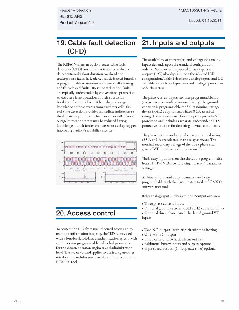
ABB 19
Feeder Protection
REF615 ANSI
Product Version 4.0
1MAC105361-PG Rev. E
Issued: 04.15.2011
20. Access control
To protect the IED from unauthorized access and to maintain information integrity, the IED is provided with a four-level, role-based authentication system with administrator programmable individual passwords for the viewer, operator, engineer and administrator level. Th e access control applies to the frontpanel user interface, the web-browser based user interface and the PCM600 tool.
21. Inputs and outputs
Th e availability of current (ct) and voltage (vt) analog inputs depends upon the standard confi guration ordered. Standard and optional binary inputs and outputs (I/O) also depend upon the selected IED confi guration. Table 4 details the analog inputs and I/O available for each confi guration and analog inputs order code characters.
Th e phase-current inputs are user programmable for 5 A or 1 A ct secondary nominal rating. Th e ground ct option is programmable for 5/1 A nominal rating, the SEF/HIZ ct option has a fi xed 0.2 A nominal rating. Th e sensitive earth fault ct option provides SEF protection and includes a separate, independent HIZ protective function for detecting downed conductors.
Th e phase-current and ground current nominal rating of 5 A or 1 A are selected in the relay soft ware. Th e nominal secondary voltage of the three-phase and ground VT inputs are user programmable.
Th e binary input turn-on thresholds are programmable from 18…176 V DC by adjusting the relay’s parameter settings.
All binary input and output contacts are freely programmable with the signal matrix tool in PCM600 soft ware user tool.
Relay analog input and binary input/output overview:
• Th ree phase-current inputs• Optional ground current or SEF/HIZ ct current input• Optional three-phase, synch check and ground VT inputs
• Two NO outputs with trip circuit monitoring• One Form C output• One Form C self-check alarm output• Additional binary inputs and outputs optional• High-speed outputs (1 ms operate time) optional
19. Cable fault detection (CFD)
Th e REF615 off ers an option feeder cable fault detection (CFD) function that is able to real-time detect extremely short duration overhead and underground faults in feeders. Th is dedicated function is programmable to monitor and detect self-clearing and fuse-cleared faults. Th ese short duration faults are typically undetectable by conventional protection where there is no operation of their substation breaker or feeder recloser. Where dispatchers gain knowledge of these events from customer calls, this real-time detection provides immediate indication to the dispatcher prior to the fi rst customer call. Overall outage restoration times may be reduced having knowledge of such feeder event as soon as they happen improving a utility’s reliability metrics.
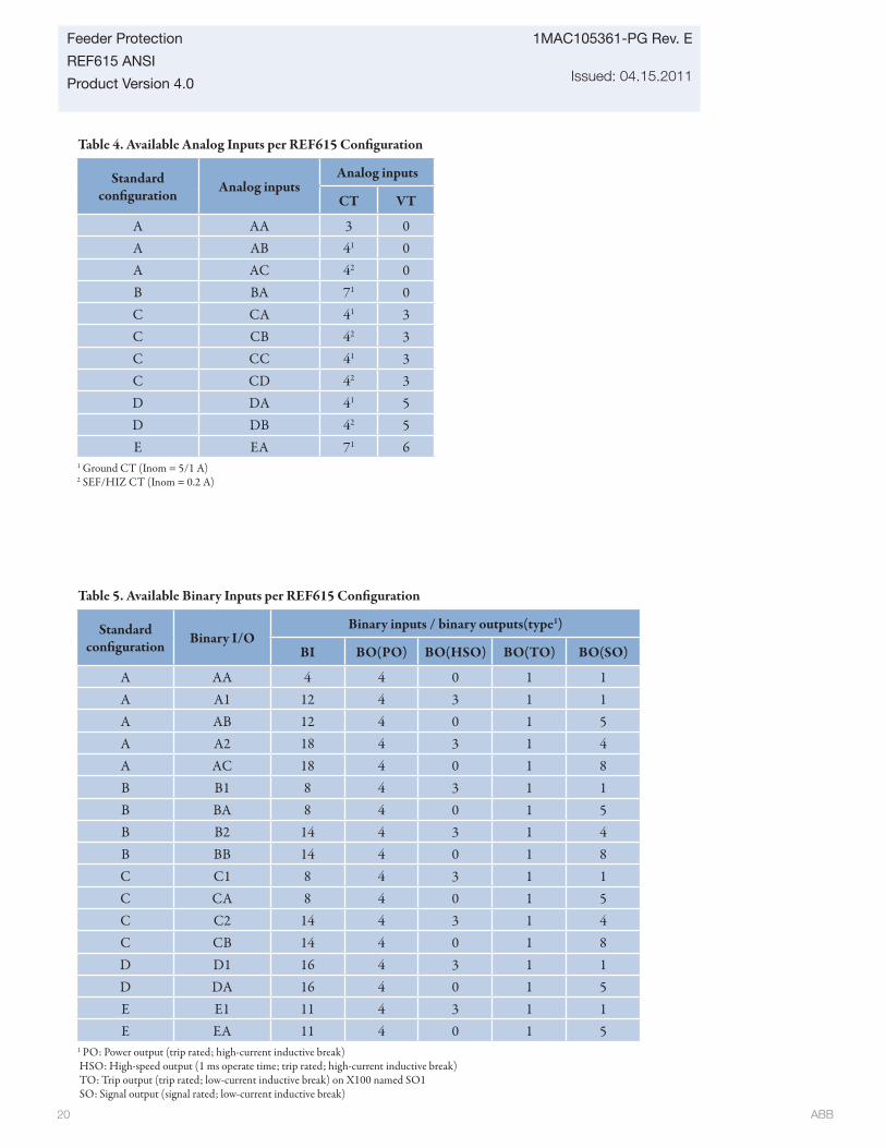
ABB 20
1MAC105361-PG Rev. E
Issued: 04.15.2011
Feeder Protection
REF615 ANSI
Product Version 4.0
Table 4. Available Analog Inputs per REF615 Confi guration
Standard confi guration Analog inputs
Analog inputs
CT VT
A AA 3 0A AB 41 0A AC 42 0B BA 71 0C CA 41 3C CB 42 3C CC 41 3C CD 42 3D DA 41 5D DB 42 5E EA 71 6
1 Ground CT (Inom = 5/1 A)2 SEF/HIZ CT (Inom = 0.2 A)
Table 5. Available Binary Inputs per REF615 Confi guration
Standard confi guration Binary I/O
Binary inputs / binary outputs(type1)
BI BO(PO) BO(HSO) BO(TO) BO(SO)
A AA 4 4 0 1 1A A1 12 4 3 1 1A AB 12 4 0 1 5A A2 18 4 3 1 4A AC 18 4 0 1 8B B1 8 4 3 1 1B BA 8 4 0 1 5B B2 14 4 3 1 4B BB 14 4 0 1 8C C1 8 4 3 1 1C CA 8 4 0 1 5C C2 14 4 3 1 4C CB 14 4 0 1 8D D1 16 4 3 1 1D DA 16 4 0 1 5E E1 11 4 3 1 1E EA 11 4 0 1 5
1 PO: Power output (trip rated; high-current inductive break) HSO: High-speed output (1 ms operate time; trip rated; high-current inductive break) TO: Trip output (trip rated; low-current inductive break) on X100 named SO1 SO: Signal output (signal rated; low-current inductive break)
ABB 21
Feeder Protection
REF615 ANSI
Product Version 4.0
1MAC105361-PG Rev. E
Issued: 04.15.2011
22. Communications
Th e relay (IED) supports a range of communication proto-cols including IEC 61850, Modbus® and DNP3.0 Level 2. Operational information and controls are available through these protocols. Certain communication functionality, e.g., horizontal communication between relays, is only enabled by the IEC 61850 communication protocol.
Th e IEC 61850 communication implementation sup-ports all monitoring and control functions. Additionally, parameter settings, disturbance recordings and fault records can be accessed using the IEC 61850 protocol. Disturbance recordings are available to any Ethernet-based application in the standard COMTRADE fi le format. Th e IED sup-ports simultaneous event reporting to fi ve diff erent clients on the communication network bus.
Th e IED can send binary signals to other IEDs (so called horizontal communication) using the IEC 61850-8-1 GOOSE (Generic Object Oriented Substation Event) profi le. Binary GOOSE messaging can, e.g., be employed for protection and interlocking-based protection schemes. Th e relay meets the GOOSE performance requirements for tripping applications in distribution substations, as defi ned by the IEC 61850 standard. Also, the IED supports the sending and receiving of analog values using GOOSE messaging. Analog GOOSE messaging enables fast transfer of analog measurement values over the network bus, thus facilitating, for example, sharing of RTD input values, such as surrounding temperature values, to other IED applica-tions.
Th e IED off ers an optional second Ethernet bus to enable the creation of a self-healing Ethernet ring topology. Th e IED communication module options include both galvanic and fi ber-optic Ethernet combinations. Th e communica-tion module including one fi ber-optic LC port and two galvanic RJ-45 ports is used when the ring between the IEDs is built using CAT5 STP cables. Th e LC port can in this case be used for connecting the IED to communication ports outside the switchgear. Th e communication module including three RJ-45 ports is used when the whole substa-tion network bus is based on CAT5 STP cabling.
Th e self-healing Ethernet ring solution enables a cost-eff ec-tive communication ring solution controlled by a managed switch with rapid spanning tree protocol (RSTP) support to be created. Th e managed switch controls the consistency of the loop, routes the data and corrects the data fl ow in case of a communication disturbance. Th e IEDs in the ring topology act as unmanaged switches forwarding
unrelated data traffi c. Th e Ethernet ring solution supports the connection of up to 30 ABB 615 series relays. If more than 30 IEDs are to be connected, it is recommended that the network is split into several rings with no more than 30 IEDs per ring. Th e self-healing Ethernet ring solution avoids single point of failure concerns and improves the reliability of the communication. Th e solution can be applied for the Ethernet-based IEC 61850, Modbus and DNP3.0 Level 2 protocols.
All communication connectors, except for the front port connector, are placed on integrated optional communica-tion modules. Th e IED can be connected to Ethernet-based communication systems via the RJ-45 connector (100Base-TX) or the fi ber-optic LC connector (100Base-FX). If connection to a serial bus is required, the 10-pin RS-485 screw-terminal or the fi ber-optic ST connector can be used.
Modbus implementation supports RTU, ASCII and TCP modes. Besides standard Modbus functionality, the IED supports retrieval of time-stamped events, changing the ac-tive setting group and uploading of the latest fault records. If a Modbus TCP connection is used, fi ve clients can be connected to the IED simultaneously. Further, Modbus serial and Modbus TCP can be used in parallel, and if required both IEC 61850 and Modbus protocols can be run simultaneously.
DNP3.0 Level 2 supports both serial and TCP modes for connection to one master. Additionally, changing of the active setting group is supported.
When the IED uses the RS-485 bus for the serial com-munication, both two- and four wire connections are supported. Termination and pull-up/down resistors can be confi gured with jumpers on the communication card so external resistors are not needed.
Th e IED supports the following time synchronization methods with a time-stamping resolution of 1 ms:
Ethernet-based:• SNTP (Simple Network Time Protocol) – primary and secondary SNTP servers supported
With special time synchronization wiring:• IRIG-B (Inter-Range Instrumentation Group - Time Code Format B)
In addition, the IED supports time synchronization via the following serial communication protocols:• Modbus
• DNP3.0 Level 2
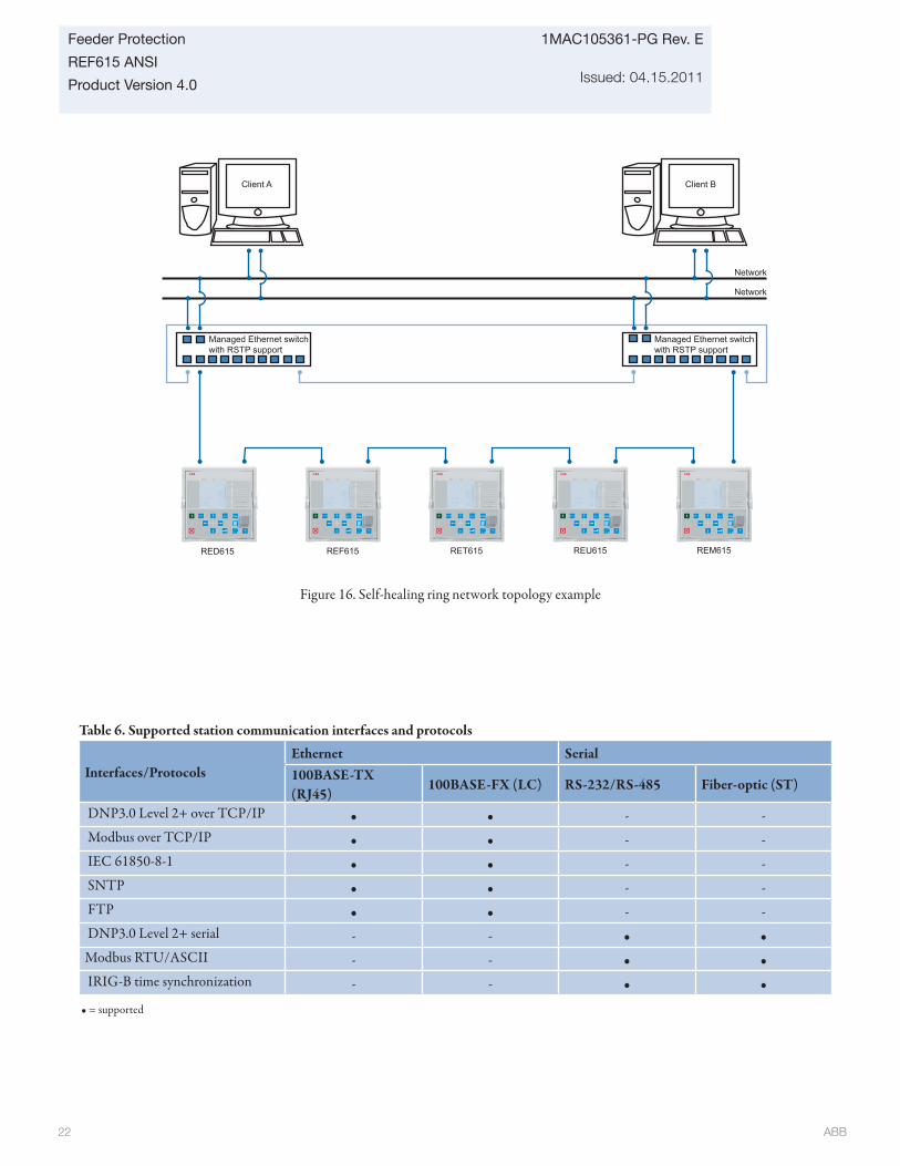
ABB 22
1MAC105361-PG Rev. E
Issued: 04.15.2011
Feeder Protection
REF615 ANSI
Product Version 4.0
Table 6. Supported station communication interfaces and protocols
Interfaces/ProtocolsEthernet Serial100BASE-TX (RJ45)
100BASE-FX (LC) RS-232/RS-485 Fiber-optic (ST)
DNP3.0 Level 2+ over TCP/IP • • - - Modbus over TCP/IP • • - - IEC 61850-8-1 • • - - SNTP • • - - FTP • • - - DNP3.0 Level 2+ serial - - • •Modbus RTU/ASCII - - • • IRIG-B time synchronization - - • •
• = supported
Managed Ethernet switchwith RSTP support
Managed Ethernet switchwith RSTP support
RED615 REF615 RET615 REU615 REM615
Client BClient A
Network
Network
Figure 16. Self-healing ring network topology example
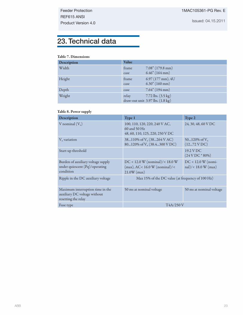
ABB 23
Feeder Protection
REF615 ANSI
Product Version 4.0
1MAC105361-PG Rev. E
Issued: 04.15.2011
23. Technical data
Table 8. Power supply
Description Type 1 Type 2V nominal (Vn) 100, 110, 120, 220, 240 V AC,
60 and 50 Hz48, 60, 110, 125, 220, 250 V DC
24, 30, 48, 60 V DC
Vn variation 38...110% of Vn (38...264 V AC)80...120% of Vn (38.4...300 V DC)
50...120% of Vn (12...72 V DC)
Start-up threshold 19.2 V DC (24 V DC * 80%)
Burden of auxiliary voltage supplyunder quiescent (Pq)/operatingcondition
DC < 12.0 W (nominal)/< 18.0 W (max), AC< 16.0 W (nominal)/< 21.0W (max)
DC < 12.0 W (nomi-nal)/< 18.0 W (max)
Ripple in the DC auxiliary voltage Max 15% of the DC value (at frequency of 100 Hz)
Maximum interruption time in theauxiliary DC voltage withoutresetting the relay
50 ms at nominal voltage 50 ms at nominal voltage
Fuse type T4A/250 V
Table 7. DimensionsDescription ValueWidth frame 7.08” (179.8 mm)
case 6.46” (164 mm)Height frame 6.97 (177 mm), 4U
case 6.30” (160 mm)Depth case 7.64” (194 mm)Weight relay 7.72 lbs. (3.5 kg)
draw-out unit 3.97 lbs. (1.8 kg)
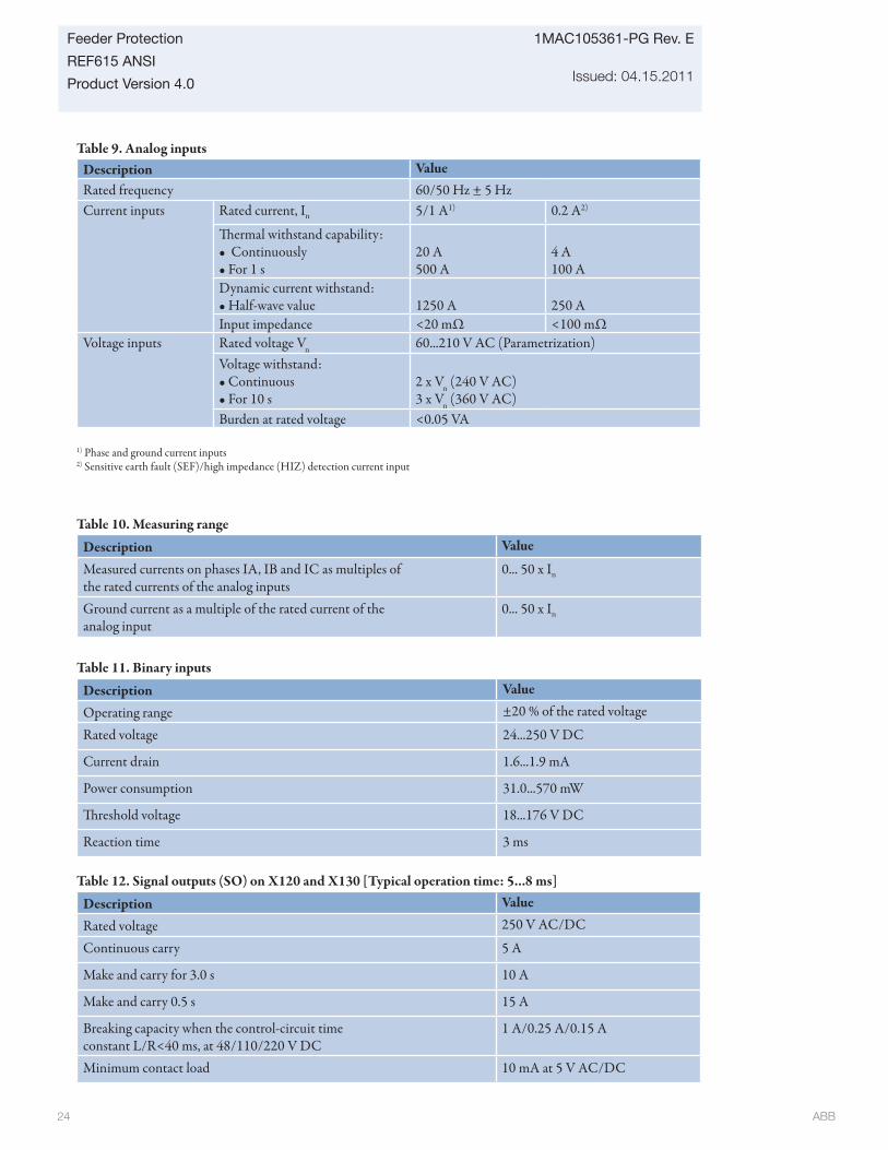
ABB 24
1MAC105361-PG Rev. E
Issued: 04.15.2011
Feeder Protection
REF615 ANSI
Product Version 4.0
Table 9. Analog inputsDescription ValueRated frequency 60/50 Hz ± 5 HzCurrent inputs Rated current, In 5/1 A1) 0.2 A2)
Th ermal withstand capability:• Continuously• For 1 s
20 A500 A
4 A100 A
Dynamic current withstand:• Half-wave value 1250 A 250 AInput impedance <20 mΩ <100 mΩ
Voltage inputs Rated voltage Vn 60...210 V AC (Parametrization)Voltage withstand:• Continuous• For 10 s
2 x Vn (240 V AC)3 x Vn (360 V AC)
Burden at rated voltage <0.05 VA
1) Phase and ground current inputs2) Sensitive earth fault (SEF)/high impedance (HIZ) detection current input
Table 10. Measuring range
Description Value
Measured currents on phases IA, IB and IC as multiples ofthe rated currents of the analog inputs
0... 50 x In
Ground current as a multiple of the rated current of theanalog input
0... 50 x In
Table 11. Binary inputs
Description Value
Operating range ±20 % of the rated voltage
Rated voltage 24...250 V DC
Current drain 1.6...1.9 mA
Power consumption 31.0...570 mW
Th reshold voltage 18...176 V DC
Reaction time 3 ms Table 12. Signal outputs (SO) on X120 and X130 [Typical operation time: 5...8 ms]
Description Value
Rated voltage 250 V AC/DC
Continuous carry 5 A
Make and carry for 3.0 s 10 A
Make and carry 0.5 s 15 A
Breaking capacity when the control-circuit timeconstant L/R<40 ms, at 48/110/220 V DC
1 A/0.25 A/0.15 A
Minimum contact load 10 mA at 5 V AC/DC
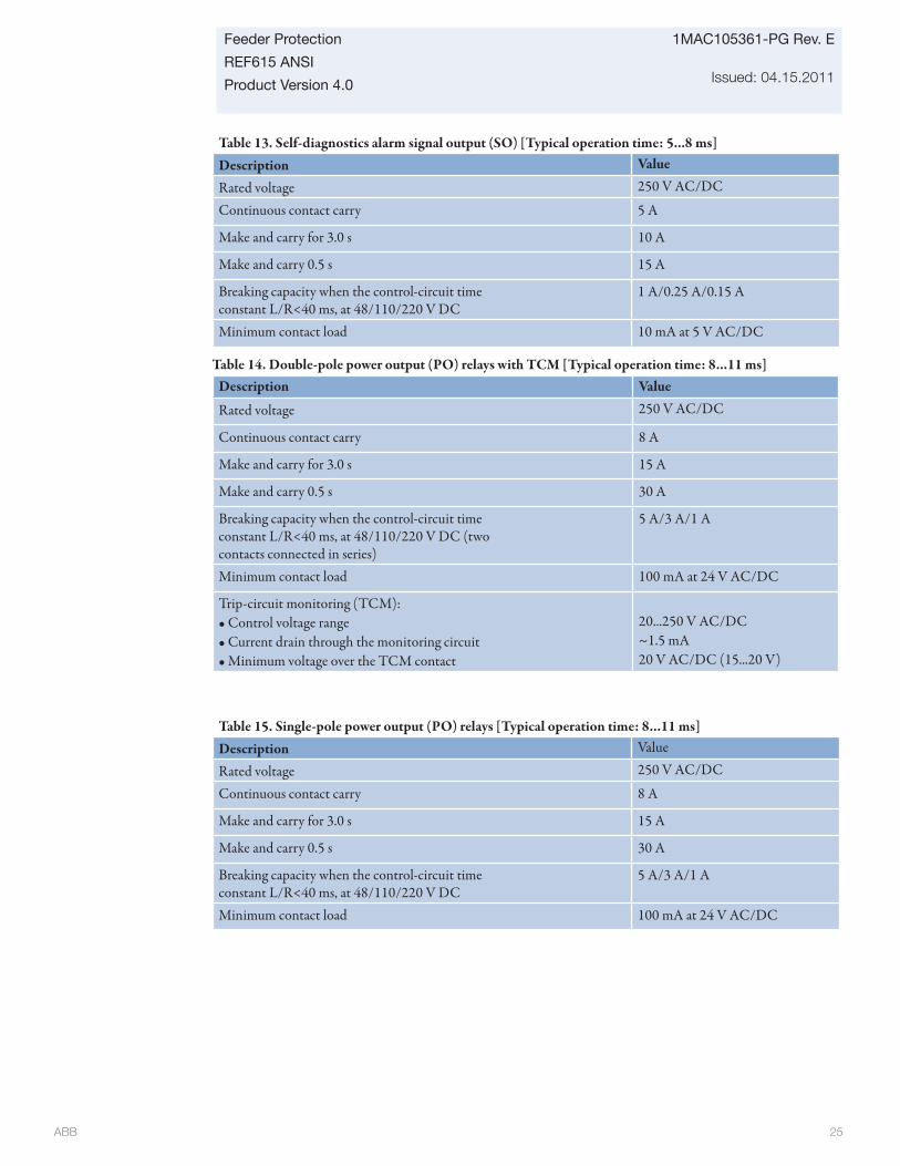
ABB 25
Feeder Protection
REF615 ANSI
Product Version 4.0
1MAC105361-PG Rev. E
Issued: 04.15.2011
Table 13. Self-diagnostics alarm signal output (SO) [Typical operation time: 5...8 ms]Description Value
Rated voltage 250 V AC/DC
Continuous contact carry 5 A
Make and carry for 3.0 s 10 A
Make and carry 0.5 s 15 A
Breaking capacity when the control-circuit timeconstant L/R<40 ms, at 48/110/220 V DC
1 A/0.25 A/0.15 A
Minimum contact load 10 mA at 5 V AC/DC
Table 14. Double-pole power output (PO) relays with TCM [Typical operation time: 8...11 ms]Description Value
Rated voltage 250 V AC/DC
Continuous contact carry 8 A
Make and carry for 3.0 s 15 A
Make and carry 0.5 s 30 A
Breaking capacity when the control-circuit timeconstant L/R<40 ms, at 48/110/220 V DC (twocontacts connected in series)
5 A/3 A/1 A
Minimum contact load 100 mA at 24 V AC/DC
Trip-circuit monitoring (TCM):• Control voltage range• Current drain through the monitoring circuit• Minimum voltage over the TCM contact
20...250 V AC/DC~1.5 mA20 V AC/DC (15...20 V)
Table 15. Single-pole power output (PO) relays [Typical operation time: 8...11 ms]Description Value
Rated voltage 250 V AC/DC
Continuous contact carry 8 A
Make and carry for 3.0 s 15 A
Make and carry 0.5 s 30 A
Breaking capacity when the control-circuit timeconstant L/R<40 ms, at 48/110/220 V DC
5 A/3 A/1 A
Minimum contact load 100 mA at 24 V AC/DC
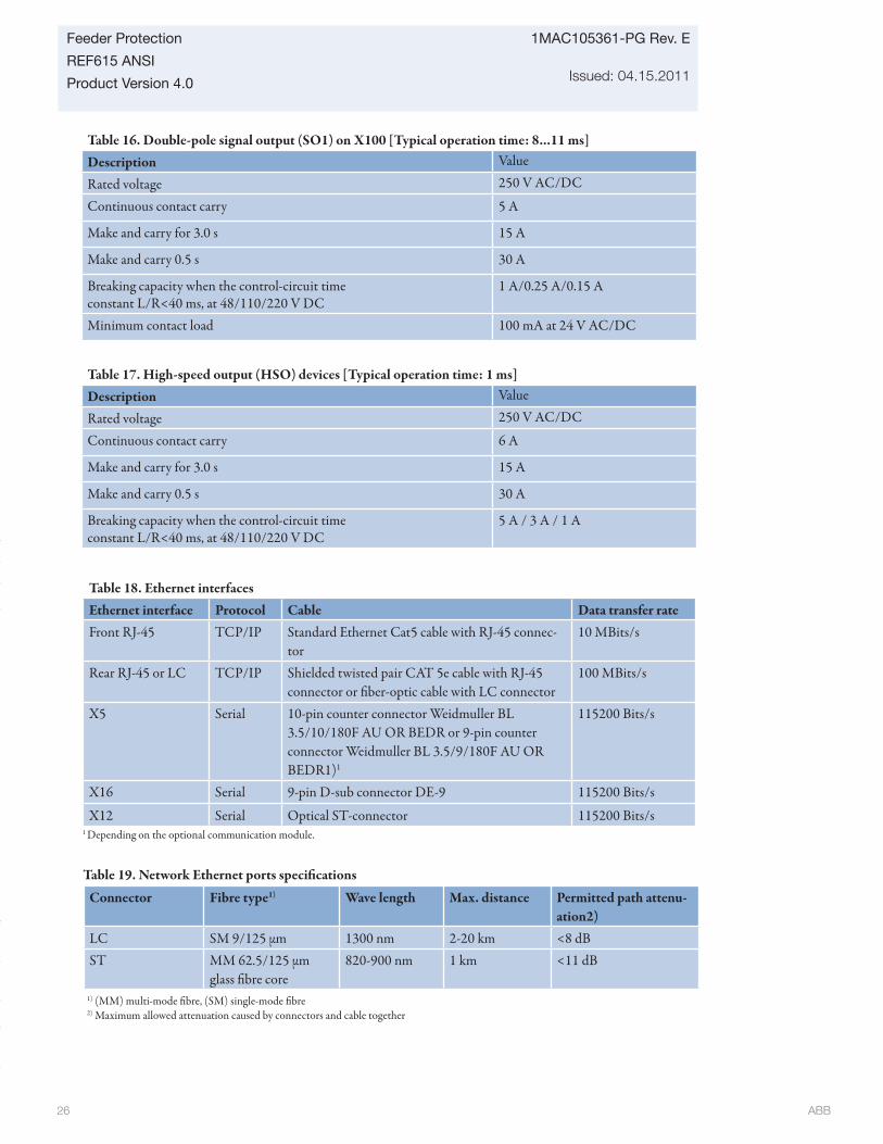
ABB 26
1MAC105361-PG Rev. E
Issued: 04.15.2011
Feeder Protection
REF615 ANSI
Product Version 4.0
Table 17. High-speed output (HSO) devices [Typical operation time: 1 ms]Description Value
Rated voltage 250 V AC/DC
Continuous contact carry 6 A
Make and carry for 3.0 s 15 A
Make and carry 0.5 s 30 A
Breaking capacity when the control-circuit timeconstant L/R<40 ms, at 48/110/220 V DC
5 A / 3 A / 1 A
Table 18. Ethernet interfacesEthernet interface Protocol Cable Data transfer rateFront RJ-45 TCP/IP Standard Ethernet Cat5 cable with RJ-45 connec-
tor10 MBits/s
Rear RJ-45 or LC TCP/IP Shielded twisted pair CAT 5e cable with RJ-45 connector or fi ber-optic cable with LC connector
100 MBits/s
X5 Serial 10-pin counter connector Weidmuller BL 3.5/10/180F AU OR BEDR or 9-pin counter connector Weidmuller BL 3.5/9/180F AU OR BEDR1)1
115200 Bits/s
X16 Serial 9-pin D-sub connector DE-9 115200 Bits/s
X12 Serial Optical ST-connector 115200 Bits/s
Table 19. Network Ethernet ports specifi cations
Connector Fibre type1) Wave length Max. distance Permitted path attenu-ation2)
LC SM 9/125 μm 1300 nm 2-20 km <8 dBST MM 62.5/125 μm
glass fi bre core820-900 nm 1 km <11 dB
1) (MM) multi-mode fi bre, (SM) single-mode fi bre2) Maximum allowed attenuation caused by connectors and cable together
Table 16. Double-pole signal output (SO1) on X100 [Typical operation time: 8...11 ms]Description Value
Rated voltage 250 V AC/DC
Continuous contact carry 5 A
Make and carry for 3.0 s 15 A
Make and carry 0.5 s 30 A
Breaking capacity when the control-circuit timeconstant L/R<40 ms, at 48/110/220 V DC
1 A/0.25 A/0.15 A
Minimum contact load 100 mA at 24 V AC/DC
1 Depending on the optional communication module.
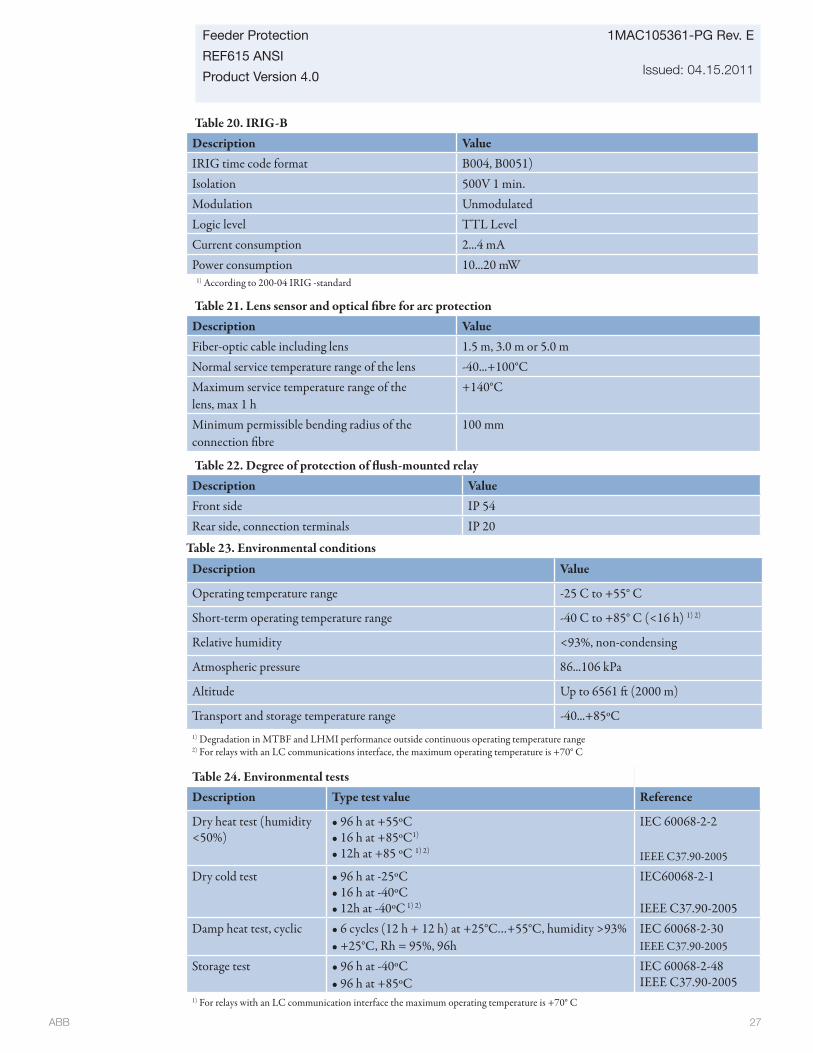
ABB 27
Feeder Protection
REF615 ANSI
Product Version 4.0
1MAC105361-PG Rev. E
Issued: 04.15.2011
Table 23. Environmental conditions
Description Value
Operating temperature range -25 C to +55° C
Short-term operating temperature range -40 C to +85° C (<16 h) 1) 2)
Relative humidity <93%, non-condensing
Atmospheric pressure 86...106 kPa
Altitude Up to 6561 ft (2000 m)
Transport and storage temperature range -40...+85ºC1) Degradation in MTBF and LHMI performance outside continuous operating temperature range2) For relays with an LC communications interface, the maximum operating temperature is +70° C
Table 20. IRIG-BDescription ValueIRIG time code format B004, B0051)Isolation 500V 1 min.Modulation UnmodulatedLogic level TTL LevelCurrent consumption 2...4 mAPower consumption 10...20 mW
Table 21. Lens sensor and optical fi bre for arc protectionDescription ValueFiber-optic cable including lens 1.5 m, 3.0 m or 5.0 mNormal service temperature range of the lens -40...+100°CMaximum service temperature range of thelens, max 1 h
+140°C
Minimum permissible bending radius of theconnection fi bre
100 mm
Table 22. Degree of protection of fl ush-mounted relayDescription ValueFront side IP 54Rear side, connection terminals IP 20
1) According to 200-04 IRIG -standard
Table 24. Environmental testsDescription Type test value Reference
Dry heat test (humidity <50%)
• 96 h at +55ºC• 16 h at +85ºC1)
• 12h at +85 ºC 1) 2)
IEC 60068-2-2
IEEE C37.90-2005
Dry cold test • 96 h at -25ºC• 16 h at -40ºC• 12h at -40ºC 1) 2)
IEC60068-2-1
IEEE C37.90-2005Damp heat test, cyclic • 6 cycles (12 h + 12 h) at +25°C…+55°C, humidity >93%
• +25°C, Rh = 95%, 96hIEC 60068-2-30IEEE C37.90-2005
Storage test • 96 h at -40ºC• 96 h at +85ºC
IEC 60068-2-48IEEE C37.90-2005
1) For relays with an LC communication interface the maximum operating temperature is +70° C
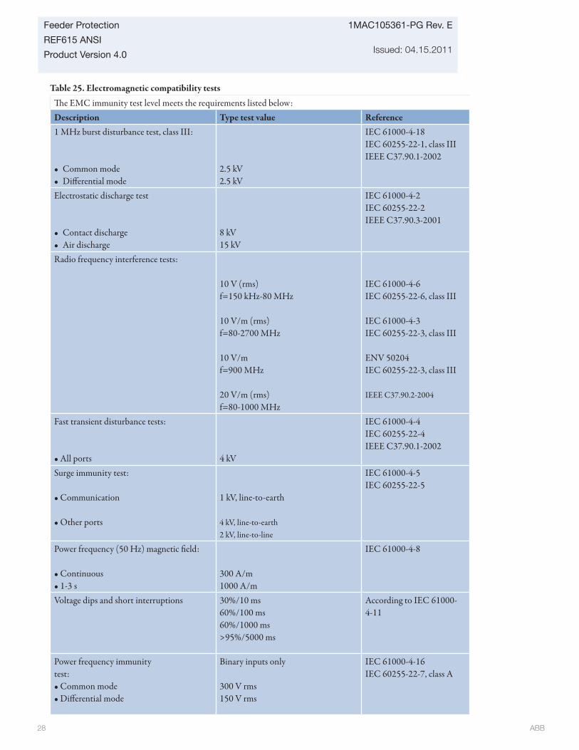
ABB 28
1MAC105361-PG Rev. E
Issued: 04.15.2011
Feeder Protection
REF615 ANSI
Product Version 4.0
Table 25. Electromagnetic compatibility tests
Th e EMC immunity test level meets the requirements listed below:Description Type test value Reference1 MHz burst disturbance test, class III:
• Common mode• Diff erential mode
2.5 kV2.5 kV
IEC 61000-4-18IEC 60255-22-1, class IIIIEEE C37.90.1-2002
Electrostatic discharge test
• Contact discharge• Air discharge
8 kV15 kV
IEC 61000-4-2IEC 60255-22-2IEEE C37.90.3-2001
Radio frequency interference tests:
10 V (rms)f=150 kHz-80 MHz
10 V/m (rms)f=80-2700 MHz
10 V/mf=900 MHz
20 V/m (rms)f=80-1000 MHz
IEC 61000-4-6IEC 60255-22-6, class III
IEC 61000-4-3IEC 60255-22-3, class III
ENV 50204IEC 60255-22-3, class III
IEEE C37.90.2-2004
Fast transient disturbance tests:
• All ports 4 kV
IEC 61000-4-4IEC 60255-22-4IEEE C37.90.1-2002
Surge immunity test:
• Communication
• Other ports
1 kV, line-to-earth
4 kV, line-to-earth2 kV, line-to-line
IEC 61000-4-5IEC 60255-22-5
Power frequency (50 Hz) magnetic fi eld:
• Continuous• 1-3 s
300 A/m 1000 A/m
IEC 61000-4-8
Voltage dips and short interruptions 30%/10 ms60%/100 ms60%/1000 ms>95%/5000 ms
According to IEC 61000-4-11
Power frequency immunitytest:• Common mode• Diff erential mode
Binary inputs only
300 V rms150 V rms
IEC 61000-4-16IEC 60255-22-7, class A
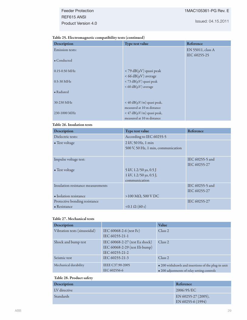
ABB 29
Feeder Protection
REF615 ANSI
Product Version 4.0
1MAC105361-PG Rev. E
Issued: 04.15.2011
Table 26. Insulation tests
Description Type test value ReferenceDielectric tests: According to IEC 60255-5• Test voltage 2 kV, 50 Hz, 1 min
500 V, 50 Hz, 1 min, communication
Impulse voltage test:
• Test voltage 5 kV, 1.2/50 μs, 0.5 J1 kV, 1.2/50 μs, 0.5 J,communication
IEC 60255-5 andIEC 60255-27
Insulation resistance measurements
• Isolation resistance >100 MΩ, 500 V DC
IEC 60255-5 andIEC 60255-27
Protective bonding resistance• Resistance <0.1 Ω (60 s)
IEC 60255-27
Table 28. Product safetyDescription ReferenceLV directive 2006/95/ECStandards EN 60255-27 (2005),
EN 60255-6 (1994)
Table 27. Mechanical tests
Description ValueVibration tests (sinusoidal) IEC 60068-2-6 (test Fc)
IEC 60255-21-1Class 2
Shock and bump test IEC 60068-2-27 (test Ea shock)IEC 60068-2-29 (test Eb bump)IEC 60255-21-2
Class 2
Seismic test IEC 60255-21-3 Class 2
Mechanical durability IEEE C37.90-2005 IEC 602556-6
• 200 withdrawls and insertions of the plug-in unit • 200 adjustments of relay setting controls
Description Type test value ReferenceEmission tests:
• Conducted
0.15-0.50 MHz
0.5-30 MHz
• Radiated
30-230 MHz
230-1000 MHz
< 79 dB(μV) quasi peak< 66 dB(μV) average< 73 dB(μV) quasi peak< 60 dB(μV) average
< 40 dB(μV/m) quasi peak,measured at 10 m distance< 47 dB(μV/m) quasi peak,measured at 10 m distance
EN 55011, class AIEC 60255-25
Table 25. Electromagnetic compatibility tests (continued)
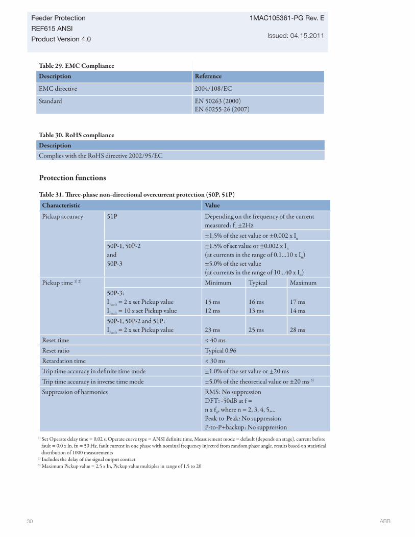
ABB 30
1MAC105361-PG Rev. E
Issued: 04.15.2011
Feeder Protection
REF615 ANSI
Product Version 4.0
Table 29. EMC Compliance Description Reference
EMC directive 2004/108/EC
Standard EN 50263 (2000)EN 60255-26 (2007)
Table 30. RoHS complianceDescriptionComplies with the RoHS directive 2002/95/EC
Protection functions
Table 31. Th ree-phase non-directional overcurrent protection (50P, 51P)
Characteristic Value
Pickup accuracy 51P Depending on the frequency of the current measured: fn ±2Hz±1.5% of the set value or ±0.002 x In
50P-1, 50P-2and50P-3
±1.5% of set value or ±0.002 x In
(at currents in the range of 0.1…10 x In)±5.0% of the set value(at currents in the range of 10…40 x In)
Pickup time 1) 2) Minimum Typical Maximum50P-3:IFault = 2 x set Pickup valueIFault = 10 x set Pickup value
15 ms12 ms
16 ms13 ms
17 ms14 ms
50P-1, 50P-2 and 51P:IFault = 2 x set Pickup value 23 ms 25 ms 28 ms
Reset time < 40 msReset ratio Typical 0.96Retardation time < 30 msTrip time accuracy in defi nite time mode ±1.0% of the set value or ±20 msTrip time accuracy in inverse time mode ±5.0% of the theoretical value or ±20 ms 3)
Suppression of harmonics RMS: No suppression DFT: -50dB at f = n x fn, where n = 2, 3, 4, 5,…Peak-to-Peak: No suppressionP-to-P+backup: No suppression
1) Set Operate delay time = 0,02 s, Operate curve type = ANSI defi nite time, Measurement mode = default (depends on stage), current before fault = 0.0 x In, fn = 50 Hz, fault current in one phase with nominal frequency injected from random phase angle, results based on statistical distribution of 1000 measurements
2) Includes the delay of the signal output contact3) Maximum Pickup value = 2.5 x In, Pickup value multiples in range of 1.5 to 20
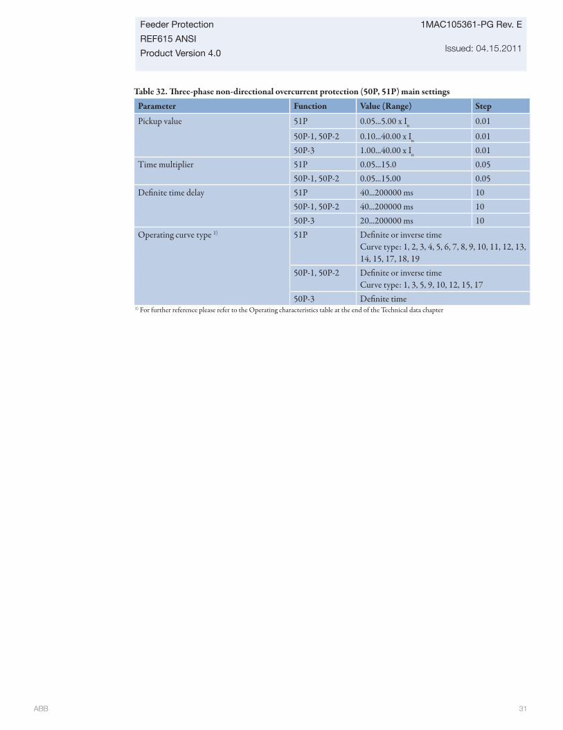
ABB 31
Feeder Protection
REF615 ANSI
Product Version 4.0
1MAC105361-PG Rev. E
Issued: 04.15.2011
Table 32. Th ree-phase non-directional overcurrent protection (50P, 51P) main settings
Parameter Function Value (Range) Step
Pickup value 51P 0.05...5.00 x In 0.01
50P-1, 50P-2 0.10...40.00 x In 0.0150P-3 1.00...40.00 x In 0.01
Time multiplier 51P 0.05...15.0 0.0550P-1, 50P-2 0.05...15.00 0.05
Defi nite time delay 51P 40...200000 ms 1050P-1, 50P-2 40...200000 ms 1050P-3 20...200000 ms 10
Operating curve type 1) 51P Defi nite or inverse time Curve type: 1, 2, 3, 4, 5, 6, 7, 8, 9, 10, 11, 12, 13, 14, 15, 17, 18, 19
50P-1, 50P-2 Defi nite or inverse timeCurve type: 1, 3, 5, 9, 10, 12, 15, 17
50P-3 Defi nite time1) For further reference please refer to the Operating characteristics table at the end of the Technical data chapter
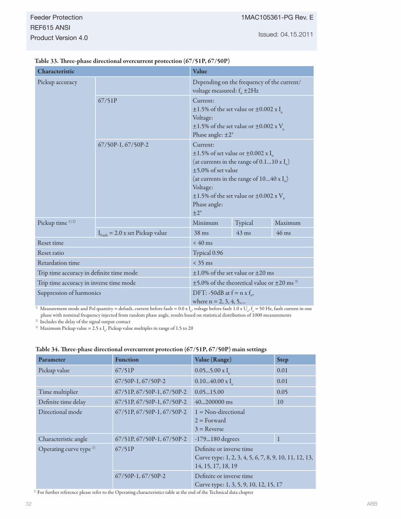
ABB 32
1MAC105361-PG Rev. E
Issued: 04.15.2011
Feeder Protection
REF615 ANSI
Product Version 4.0
Table 34. Th ree-phase directional overcurrent protection (67/51P, 67/50P) main settings
Parameter Function Value (Range) Step
Pickup value 67/51P 0.05...5.00 x In 0.01
67/50P-1, 67/50P-2 0.10...40.00 x In 0.01
Time multiplier 67/51P, 67/50P-1, 67/50P-2 0.05...15.00 0.05Defi nite time delay 67/51P, 67/50P-1, 67/50P-2 40...200000 ms 10Directional mode 67/51P, 67/50P-1, 67/50P-2 1 = Non-directional
2 = Forward3 = Reverse
Characteristic angle 67/51P, 67/50P-1, 67/50P-2 -179...180 degrees 1Operating curve type 1) 67/51P Defi nite or inverse time
Curve type: 1, 2, 3, 4, 5, 6, 7, 8, 9, 10, 11, 12, 13, 14, 15, 17, 18, 19
67/50P-1, 67/50P-2 Defi nite or inverse timeCurve type: 1, 3, 5, 9, 10, 12, 15, 17
1) For further reference please refer to the Operating characteristics table at the end of the Technical data chapter
Table 33. Th ree-phase directional overcurrent protection (67/51P, 67/50P)
Characteristic Value
Pickup accuracy Depending on the frequency of the current/voltage measured: fn ±2Hz
67/51P Current:±1.5% of the set value or ±0.002 x In
Voltage: ±1.5% of the set value or ±0.002 x Vn
Phase angle: ±2°67/50P-1, 67/50P-2 Current:
±1.5% of set value or ±0.002 x In
(at currents in the range of 0.1…10 x In)±5.0% of set value(at currents in the range of 10…40 x In)Voltage:±1.5% of the set value or ±0.002 x Vn
Phase angle:±2°
Pickup time 1) 2) Minimum Typical MaximumIFault = 2.0 x set Pickup value 38 ms 43 ms 46 ms
Reset time < 40 msReset ratio Typical 0.96Retardation time < 35 msTrip time accuracy in defi nite time mode ±1.0% of the set value or ±20 msTrip time accuracy in inverse time mode ±5.0% of the theoretical value or ±20 ms 3)
Suppression of harmonics DFT: -50dB at f = n x fn, where n = 2, 3, 4, 5,…
1) Measurement mode and Pol quantity = default, current before fault = 0.0 x In, voltage before fault 1.0 x Un, fn = 50 Hz, fault current in one phase with nominal frequency injected from random phase angle, results based on statistical distribution of 1000 measurements
2) Includes the delay of the signal output contact3) Maximum Pickup value = 2.5 x In, Pickup value multiples in range of 1.5 to 20
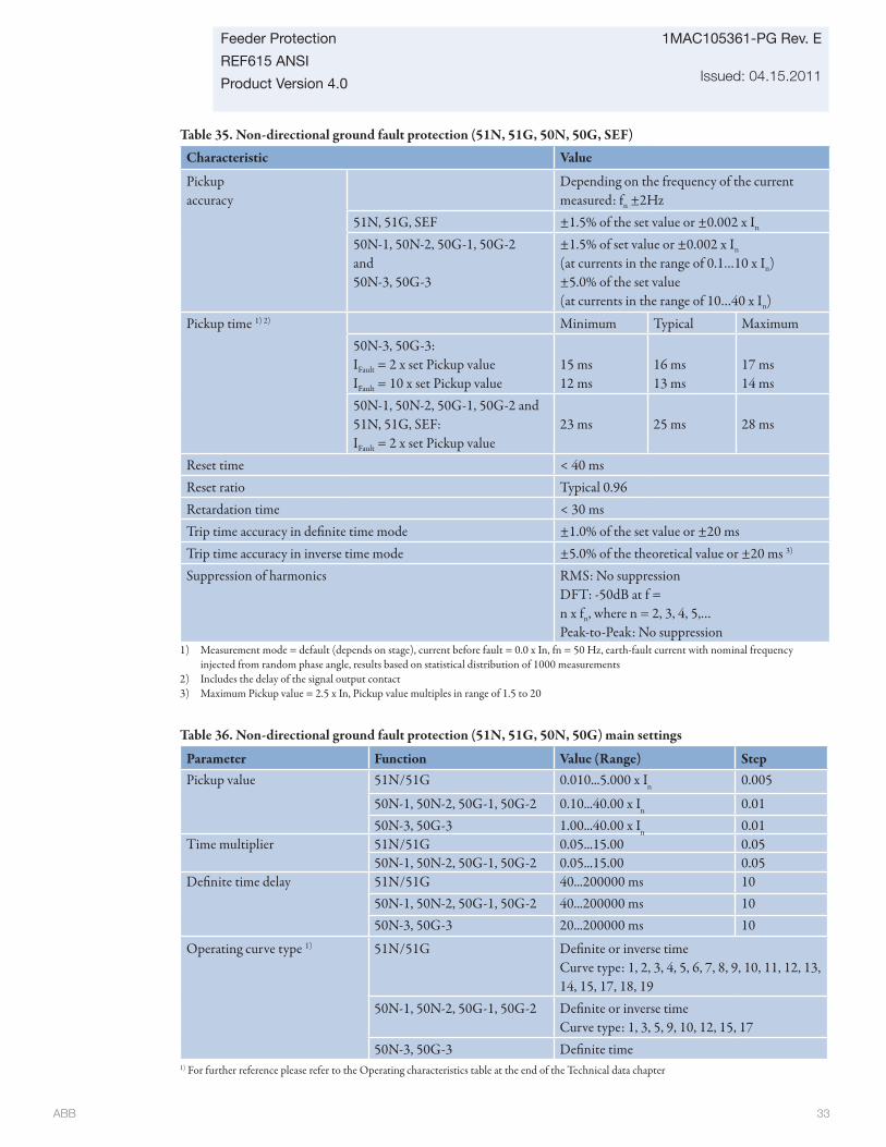
ABB 33
Feeder Protection
REF615 ANSI
Product Version 4.0
1MAC105361-PG Rev. E
Issued: 04.15.2011
Table 35. Non-directional ground fault protection (51N, 51G, 50N, 50G, SEF)
Characteristic Value
Pickup accuracy
Depending on the frequency of the current measured: fn ±2Hz
51N, 51G, SEF ±1.5% of the set value or ±0.002 x In
50N-1, 50N-2, 50G-1, 50G-2 and50N-3, 50G-3
±1.5% of set value or ±0.002 x In
(at currents in the range of 0.1…10 x In)±5.0% of the set value(at currents in the range of 10…40 x In)
Pickup time 1) 2) Minimum Typical Maximum50N-3, 50G-3:IFault = 2 x set Pickup valueIFault = 10 x set Pickup value
15 ms12 ms
16 ms13 ms
17 ms14 ms
50N-1, 50N-2, 50G-1, 50G-2 and 51N, 51G, SEF:IFault = 2 x set Pickup value
23 ms 25 ms 28 ms
Reset time < 40 msReset ratio Typical 0.96Retardation time < 30 msTrip time accuracy in defi nite time mode ±1.0% of the set value or ±20 msTrip time accuracy in inverse time mode ±5.0% of the theoretical value or ±20 ms 3)
Suppression of harmonics RMS: No suppression DFT: -50dB at f = n x fn, where n = 2, 3, 4, 5,…Peak-to-Peak: No suppression
1) Measurement mode = default (depends on stage), current before fault = 0.0 x In, fn = 50 Hz, earth-fault current with nominal frequency injected from random phase angle, results based on statistical distribution of 1000 measurements
2) Includes the delay of the signal output contact3) Maximum Pickup value = 2.5 x In, Pickup value multiples in range of 1.5 to 20
Table 36. Non-directional ground fault protection (51N, 51G, 50N, 50G) main settings
Parameter Function Value (Range) StepPickup value 51N/51G 0.010...5.000 x In 0.005
50N-1, 50N-2, 50G-1, 50G-2 0.10...40.00 x In 0.0150N-3, 50G-3 1.00...40.00 x In 0.01
Time multiplier 51N/51G 0.05...15.00 0.0550N-1, 50N-2, 50G-1, 50G-2 0.05...15.00 0.05
Defi nite time delay 51N/51G 40...200000 ms 1050N-1, 50N-2, 50G-1, 50G-2 40...200000 ms 1050N-3, 50G-3 20...200000 ms 10
Operating curve type 1) 51N/51G Defi nite or inverse timeCurve type: 1, 2, 3, 4, 5, 6, 7, 8, 9, 10, 11, 12, 13, 14, 15, 17, 18, 19
50N-1, 50N-2, 50G-1, 50G-2 Defi nite or inverse timeCurve type: 1, 3, 5, 9, 10, 12, 15, 17
50N-3, 50G-3 Defi nite time1) For further reference please refer to the Operating characteristics table at the end of the Technical data chapter
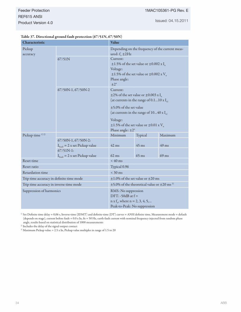
ABB 34
1MAC105361-PG Rev. E
Issued: 04.15.2011
Feeder Protection
REF615 ANSI
Product Version 4.0
Table 37. Directional ground fault protection (67/51N, 67/50N)Characteristic Value
Pickup accuracy
Depending on the frequency of the current meas-ured: fn ±2Hz
67/51N Current: ±1.5% of the set value or ±0.002 x In
Voltage: ±1.5% of the set value or ±0.002 x Vn
Phase angle: ±2°
67/50N-1, 67/50N-2 Current: ±2% of the set value or ±0.003 x In
(at currents in the range of 0.1…10 x In)
±5.0% of the set value (at currents in the range of 10…40 x In)
Voltage:±1.5% of the set value or ±0.01 x Vn
Phase angle: ±2°Pickup time 1) 2) Minimum Typical Maximum
67/50N-1, 67/50N-2:IFault = 2 x set Pickup value 42 ms 45 ms 49 ms67/51N-1:IFault = 2 x set Pickup value 62 ms 65 ms 69 ms
Reset time < 40 msReset ratio Typical 0.96Retardation time < 30 msTrip time accuracy in defi nite time mode ±1.0% of the set value or ±20 msTrip time accuracy in inverse time mode ±5.0% of the theoretical value or ±20 ms 3)
Suppression of harmonics RMS: No suppression DFT: -50dB at f = n x fn, where n = 2, 3, 4, 5,…Peak-to-Peak: No suppression
1) Set Defi nite time delay = 0,06 s, Inverse-time (IDMT) and defi nite-time (DT) curves = ANSI defi nite time, Measurement mode = default (depends on stage), current before fault = 0.0 x In, fn = 50 Hz, earth-fault current with nominal frequency injected from random phase angle, results based on statistical distribution of 1000 measurements
2) Includes the delay of the signal output contact3) Maximum Pickup value = 2.5 x In, Pickup value multiples in range of 1.5 to 20
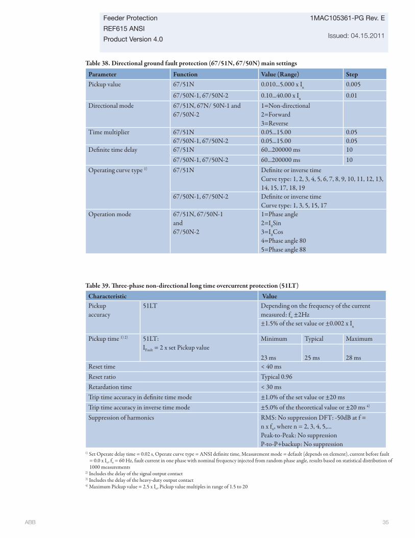
ABB 35
Feeder Protection
REF615 ANSI
Product Version 4.0
1MAC105361-PG Rev. E
Issued: 04.15.2011
Table 38. Directional ground fault protection (67/51N, 67/50N) main settings
Parameter Function Value (Range) StepPickup value 67/51N 0.010...5.000 x In 0.005
67/50N-1, 67/50N-2 0.10...40.00 x In 0.01Directional mode 67/51N, 67N/ 50N-1 and
67/50N-21=Non-directional2=Forward3=Reverse
Time multiplier 67/51N 0.05...15.00 0.0567/50N-1, 67/50N-2 0.05...15.00 0.05
Defi nite time delay 67/51N 60...200000 ms 1067/50N-1, 67/50N-2 60...200000 ms 10
Operating curve type 1) 67/51N Defi nite or inverse timeCurve type: 1, 2, 3, 4, 5, 6, 7, 8, 9, 10, 11, 12, 13, 14, 15, 17, 18, 19
67/50N-1, 67/50N-2 Defi nite or inverse timeCurve type: 1, 3, 5, 15, 17
Operation mode 67/51N, 67/50N-1 and67/50N-2
1=Phase angle2=I0Sin3=I0Cos4=Phase angle 805=Phase angle 88
Table 39. Th ree-phase non-directional long time overcurrent protection (51LT)
Characteristic ValuePickup accuracy
51LT Depending on the frequency of the current measured: fn ±2Hz±1.5% of the set value or ±0.002 x In
Pickup time 1) 2) 51LT:IFault = 2 x set Pickup value
Minimum Typical Maximum
23 ms 25 ms 28 msReset time < 40 msReset ratio Typical 0.96Retardation time < 30 msTrip time accuracy in defi nite time mode ±1.0% of the set value or ±20 msTrip time accuracy in inverse time mode ±5.0% of the theoretical value or ±20 ms 4)
Suppression of harmonics RMS: No suppression DFT: -50dB at f = n x fn, where n = 2, 3, 4, 5,…Peak-to-Peak: No suppressionP-to-P+backup: No suppression
1) Set Operate delay time = 0.02 s, Operate curve type = ANSI defi nite time, Measurement mode = default (depends on element), current before fault = 0.0 x In, fn = 60 Hz, fault current in one phase with nominal frequency injected from random phase angle, results based on statistical distribution of 1000 measurements
2) Includes the delay of the signal output contact3) Includes the delay of the heavy-duty output contact4) Maximum Pickup value = 2.5 x In, Pickup value multiples in range of 1.5 to 20
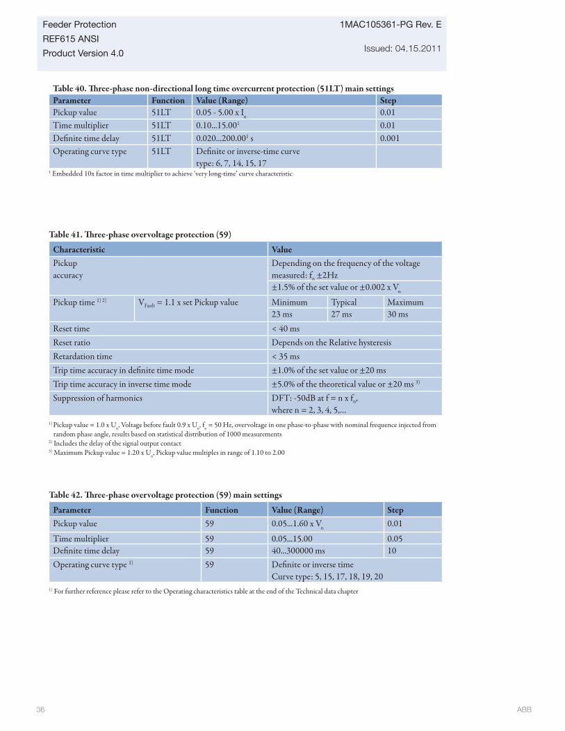
ABB 36
1MAC105361-PG Rev. E
Issued: 04.15.2011
Feeder Protection
REF615 ANSI
Product Version 4.0
Table 41. Th ree-phase overvoltage protection (59)
Characteristic ValuePickup accuracy
Depending on the frequency of the voltage measured: fn ±2Hz±1.5% of the set value or ±0.002 x Vn
Pickup time 1) 2) VFault = 1.1 x set Pickup value Minimum Typical Maximum23 ms 27 ms 30 ms
Reset time < 40 msReset ratio Depends on the Relative hysteresisRetardation time < 35 msTrip time accuracy in defi nite time mode ±1.0% of the set value or ±20 msTrip time accuracy in inverse time mode ±5.0% of the theoretical value or ±20 ms 3)
Suppression of harmonics DFT: -50dB at f = n x fn, where n = 2, 3, 4, 5,…
1) Pickup value = 1.0 x Un, Voltage before fault 0.9 x Un, fn = 50 Hz, overvoltage in one phase-to-phase with nominal frequence injected from random phase angle, results based on statistical distribution of 1000 measurements
2) Includes the delay of the signal output contact3) Maximum Pickup value = 1.20 x Un, Pickup value multiples in range of 1.10 to 2.00
1 Embedded 10x factor in time multiplier to achieve ‘very long-time’ curve characteristic
Table 42. Th ree-phase overvoltage protection (59) main settings
Parameter Function Value (Range) StepPickup value 59 0.05...1.60 x Vn 0.01
Time multiplier 59 0.05...15.00 0.05Defi nite time delay 59 40...300000 ms 10Operating curve type 1) 59 Defi nite or inverse time
Curve type: 5, 15, 17, 18, 19, 201) For further reference please refer to the Operating characteristics table at the end of the Technical data chapter
Table 40. Th ree-phase non-directional long time overcurrent protection (51LT) main settingsParameter Function Value (Range) StepPickup value 51LT 0.05 - 5.00 x In 0.01Time multiplier 51LT 0.10...15.001 0.01Defi nite time delay 51LT 0.020...200.001 s 0.001Operating curve type 51LT Defi nite or inverse-time curve
type: 6, 7, 14, 15, 17
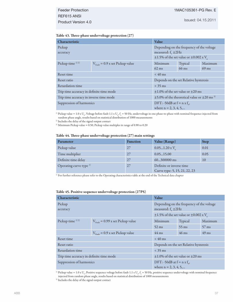
ABB 37
Feeder Protection
REF615 ANSI
Product Version 4.0
1MAC105361-PG Rev. E
Issued: 04.15.2011
Table 43. Th ree-phase undervoltage protection (27)
Characteristic ValuePickup accuracy
Depending on the frequency of the voltage measured: fn ±2Hz±1.5% of the set value or ±0.002 x Vn
Pickup time 1) 2) VFault = 0.9 x set Pickup value Minimum Typical Maximum62 ms 66 ms 69 ms
Reset time < 40 msReset ratio Depends on the set Relative hysteresisRetardation time < 35 msTrip time accuracy in defi nite time mode ±1.0% of the set value or ±20 msTrip time accuracy in inverse time mode ±5.0% of the theoretical value or ±20 ms 3)
Suppression of harmonics DFT: -50dB at f = n x fn, where n = 2, 3, 4, 5,…
Table 44. Th ree-phase undervoltage protection (27) main settings
Parameter Function Value (Range) Step
Pickup value 27 0.05...1.20 x Vn 0.01
Time multiplier 27 0.05...15.00 0.05Defi nite time delay 27 60...300000 ms 10Operating curve type 1) 27 Defi nite or inverse time
Curve type: 5, 15, 21, 22, 23
1) Pickup value = 1.0 x Un, Voltage before fault 1.1 x Un, fn = 50 Hz, undervoltage in one phase-to-phase with nominal frequence injected from random phase angle, results based on statistical distribution of 1000 measurements
2) Includes the delay of the signal output contact3) Minimum Pickup value = 0.50, Pickup value multiples in range of 0.90 to 0.20
1) For further reference please refer to the Operating characteristics table at the end of the Technical data chapter
Table 45. Positive sequence undervoltage protection (27PS)
Characteristic Value
Pickup accuracy
Depending on the frequency of the voltage measured: fn ±2Hz±1.5% of the set value or ±0.002 x Vn
Pickup time 1) 2) VFault = 0.99 x set Pickup value Minimum Typical Maximum52 ms 55 ms 57 ms
VFault = 0.9 x set Pickup value 44 ms 46 ms 49 msReset time < 40 msReset ratio Depends on the set Relative hysteresisRetardation time < 35 msTrip time accuracy in defi nite time mode ±1.0% of the set value or ±20 msSuppression of harmonics DFT: -50dB at f = n x fn,
where n = 2, 3, 4, 5,…1) Pickup value = 1.0 x Un, Positive sequence voltage before fault 1.1 x Un, fn = 50 Hz, positive sequence undervoltage with nominal frequence
injected from random phase angle, results based on statistical distribution of 1000 measurements2) Includes the delay of the signal output contact
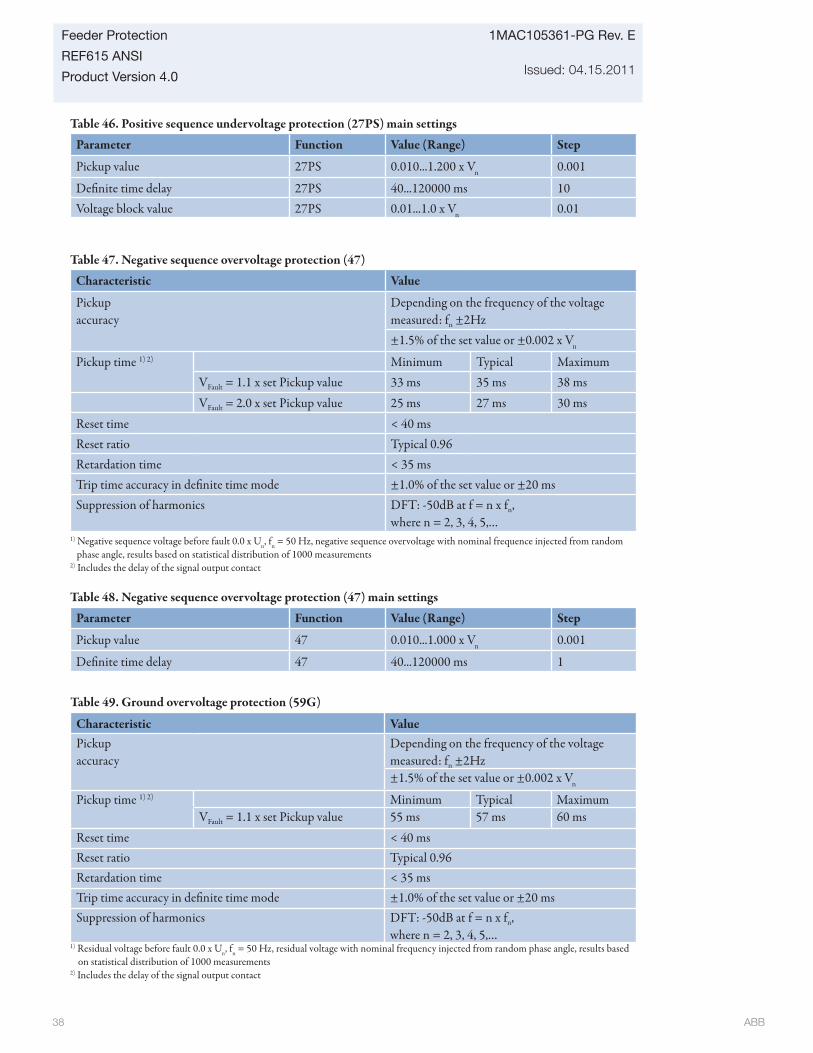
ABB 38
1MAC105361-PG Rev. E
Issued: 04.15.2011
Feeder Protection
REF615 ANSI
Product Version 4.0
Table 46. Positive sequence undervoltage protection (27PS) main settings
Parameter Function Value (Range) Step
Pickup value 27PS 0.010...1.200 x Vn 0.001
Defi nite time delay 27PS 40...120000 ms 10Voltage block value 27PS 0.01...1.0 x Vn 0.01
Table 47. Negative sequence overvoltage protection (47)
Characteristic Value
Pickup accuracy
Depending on the frequency of the voltage measured: fn ±2Hz±1.5% of the set value or ±0.002 x Vn
Pickup time 1) 2) Minimum Typical MaximumVFault = 1.1 x set Pickup value 33 ms 35 ms 38 msVFault = 2.0 x set Pickup value 25 ms 27 ms 30 ms
Reset time < 40 msReset ratio Typical 0.96Retardation time < 35 msTrip time accuracy in defi nite time mode ±1.0% of the set value or ±20 msSuppression of harmonics DFT: -50dB at f = n x fn,
where n = 2, 3, 4, 5,…1) Negative sequence voltage before fault 0.0 x Un, fn = 50 Hz, negative sequence overvoltage with nominal frequence injected from random
phase angle, results based on statistical distribution of 1000 measurements2) Includes the delay of the signal output contact
Table 48. Negative sequence overvoltage protection (47) main settings
Parameter Function Value (Range) Step
Pickup value 47 0.010...1.000 x Vn 0.001
Defi nite time delay 47 40...120000 ms 1
Table 49. Ground overvoltage protection (59G)
Characteristic ValuePickup accuracy
Depending on the frequency of the voltage measured: fn ±2Hz±1.5% of the set value or ±0.002 x Vn
Pickup time 1) 2) Minimum Typical MaximumVFault = 1.1 x set Pickup value 55 ms 57 ms 60 ms
Reset time < 40 msReset ratio Typical 0.96Retardation time < 35 msTrip time accuracy in defi nite time mode ±1.0% of the set value or ±20 msSuppression of harmonics DFT: -50dB at f = n x fn,
where n = 2, 3, 4, 5,…1) Residual voltage before fault 0.0 x Un, fn = 50 Hz, residual voltage with nominal frequency injected from random phase angle, results based
on statistical distribution of 1000 measurements2) Includes the delay of the signal output contact
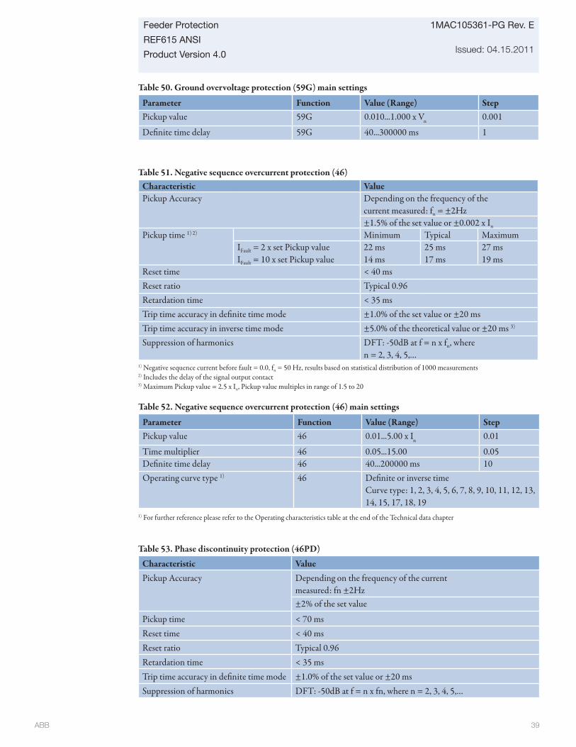
ABB 39
Feeder Protection
REF615 ANSI
Product Version 4.0
1MAC105361-PG Rev. E
Issued: 04.15.2011
Table 50. Ground overvoltage protection (59G) main settings
Parameter Function Value (Range) StepPickup value 59G 0.010...1.000 x Vn 0.001
Defi nite time delay 59G 40...300000 ms 1
Table 51. Negative sequence overcurrent protection (46)Characteristic ValuePickup Accuracy Depending on the frequency of the
current measured: fn = ±2Hz±1.5% of the set value or ±0.002 x In
Pickup time 1) 2) Minimum Typical MaximumIFault = 2 x set Pickup valueIFault = 10 x set Pickup value
22 ms14 ms
25 ms17 ms
27 ms19 ms
Reset time < 40 msReset ratio Typical 0.96Retardation time < 35 msTrip time accuracy in defi nite time mode ±1.0% of the set value or ±20 msTrip time accuracy in inverse time mode ±5.0% of the theoretical value or ±20 ms 3)
Suppression of harmonics DFT: -50dB at f = n x fn, where n = 2, 3, 4, 5,…
1) Negative sequence current before fault = 0.0, fn = 50 Hz, results based on statistical distribution of 1000 measurements2) Includes the delay of the signal output contact3) Maximum Pickup value = 2.5 x In, Pickup value multiples in range of 1.5 to 20
Table 53. Phase discontinuity protection (46PD)
Characteristic ValuePickup Accuracy Depending on the frequency of the current
measured: fn ±2Hz±2% of the set value
Pickup time < 70 msReset time < 40 msReset ratio Typical 0.96Retardation time < 35 msTrip time accuracy in defi nite time mode ±1.0% of the set value or ±20 msSuppression of harmonics DFT: -50dB at f = n x fn, where n = 2, 3, 4, 5,…
Table 52. Negative sequence overcurrent protection (46) main settings
Parameter Function Value (Range) StepPickup value 46 0.01...5.00 x In 0.01
Time multiplier 46 0.05...15.00 0.05Defi nite time delay 46 40...200000 ms 10Operating curve type 1) 46 Defi nite or inverse time
Curve type: 1, 2, 3, 4, 5, 6, 7, 8, 9, 10, 11, 12, 13, 14, 15, 17, 18, 19
1) For further reference please refer to the Operating characteristics table at the end of the Technical data chapter
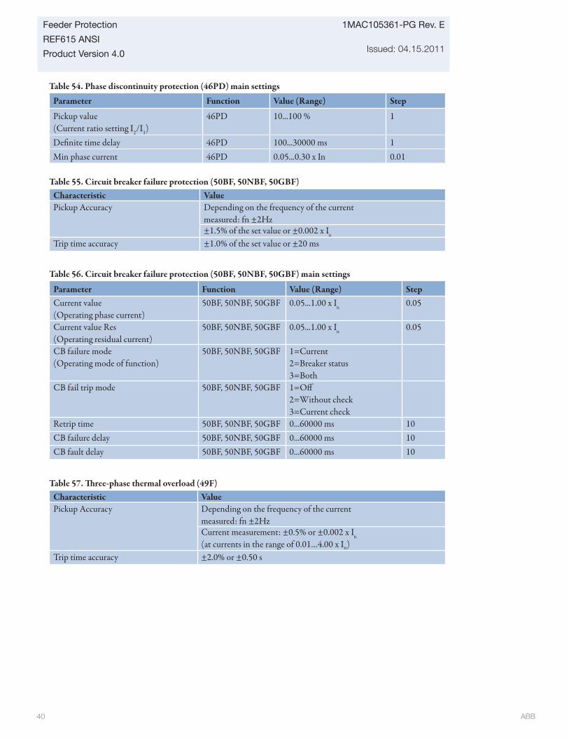
ABB 40
1MAC105361-PG Rev. E
Issued: 04.15.2011
Feeder Protection
REF615 ANSI
Product Version 4.0
Table 54. Phase discontinuity protection (46PD) main settings
Parameter Function Value (Range) Step
Pickup value(Current ratio setting I2/I1)
46PD 10...100 % 1
Defi nite time delay 46PD 100...30000 ms 1Min phase current 46PD 0.05...0.30 x In 0.01
Table 57. Th ree-phase thermal overload (49F)Characteristic ValuePickup Accuracy Depending on the frequency of the current
measured: fn ±2HzCurrent measurement: ±0.5% or ±0.002 x In
(at currents in the range of 0.01…4.00 x In)Trip time accuracy ±2.0% or ±0.50 s
Table 56. Circuit breaker failure protection (50BF, 50NBF, 50GBF) main settings
Parameter Function Value (Range) StepCurrent value(Operating phase current)
50BF, 50NBF, 50GBF 0.05...1.00 x In 0.05
Current value Res(Operating residual current)
50BF, 50NBF, 50GBF 0.05...1.00 x In 0.05
CB failure mode(Operating mode of function)
50BF, 50NBF, 50GBF 1=Current2=Breaker status3=Both
CB fail trip mode 50BF, 50NBF, 50GBF 1=Off 2=Without check3=Current check
Retrip time 50BF, 50NBF, 50GBF 0...60000 ms 10CB failure delay 50BF, 50NBF, 50GBF 0...60000 ms 10CB fault delay 50BF, 50NBF, 50GBF 0...60000 ms 10
Table 55. Circuit breaker failure protection (50BF, 50NBF, 50GBF)Characteristic ValuePickup Accuracy Depending on the frequency of the current
measured: fn ±2Hz±1.5% of the set value or ±0.002 x In
Trip time accuracy ±1.0% of the set value or ±20 ms
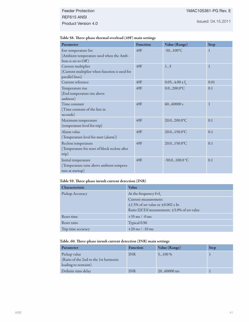
ABB 41
Feeder Protection
REF615 ANSI
Product Version 4.0
1MAC105361-PG Rev. E
Issued: 04.15.2011
Table 58. Th ree-phase thermal overload (49F) main settings
Parameter Function Value (Range) StepEnv temperature Set(Ambient temperature used when the Amb-Sens is set to Off )
49F -50...100°C 1
Current multiplier(Current multiplier when function is used for parallel lines)
49F 1...5 1
Current reference 49F 0.05...4.00 x In 0.01Temperature rise(End temperature rise above ambient)
49F 0.0...200.0°C 0.1
Time constant(Time constant of the line in seconds)
49F 60...60000 s 1
Maximum temperature(temperature level for trip)
49F 20.0...200.0°C 0.1
Alarm value(Temperature level for start (alarm))
49F 20.0...150.0°C 0.1
Reclose temperature(Temperature for reset of block reclose aft er trip)
49F 20.0...150.0°C 0.1
Initial temperature(Temperature raise above ambient tempera-ture at startup)
49F -50.0...100.0 °C 0.1
Table 59. Th ree-phase inrush current detection (INR)
Characteristic ValuePickup Accuracy At the frequency f=fn
Current measurement: ±1.5% of set value or ±0.002 x InRatio I2f/I1f measurement: ±5.0% of set value
Reset time +35 ms / -0 msReset ratio Typical 0.96Trip time accuracy +20 ms / -10 ms
Table. 60. Th ree-phase inrush current detection (INR) main settings
Parameter Function Value (Range) Step
Pickup value(Ratio of the 2nd to the 1st harmonic leading to restraint)
INR 5...100 % 1
Defi nite time delay INR 20...60000 ms 1
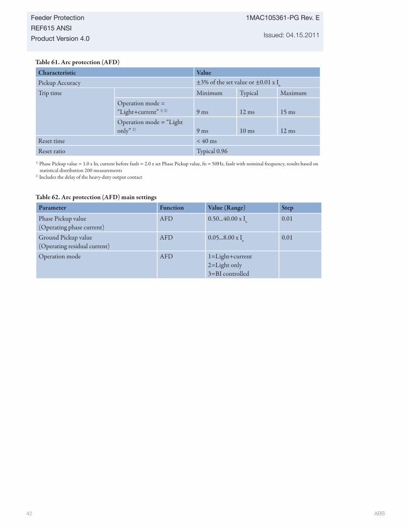
ABB 42
1MAC105361-PG Rev. E
Issued: 04.15.2011
Feeder Protection
REF615 ANSI
Product Version 4.0
Table 61. Arc protection (AFD)
Characteristic ValuePickup Accuracy ±3% of the set value or ±0.01 x In
Trip time Minimum Typical MaximumOperation mode = “Light+current” 1) 2) 9 ms 12 ms 15 msOperation mode = “Light only” 2) 9 ms 10 ms 12 ms
Reset time < 40 msReset ratio Typical 0.96
1) Phase Pickup value = 1.0 x In, current before fault = 2.0 x set Phase Pickup value, fn = 50Hz, fault with nominal frequency, results based on statistical distribution 200 measurements
2) Includes the delay of the heavy-duty output contact
Table 62. Arc protection (AFD) main settings
Parameter Function Value (Range) Step
Phase Pickup value(Operating phase current)
AFD 0.50...40.00 x In 0.01
Ground Pickup value(Operating residual current)
AFD 0.05...8.00 x In 0.01
Operation mode AFD 1=Light+current2=Light only3=BI controlled
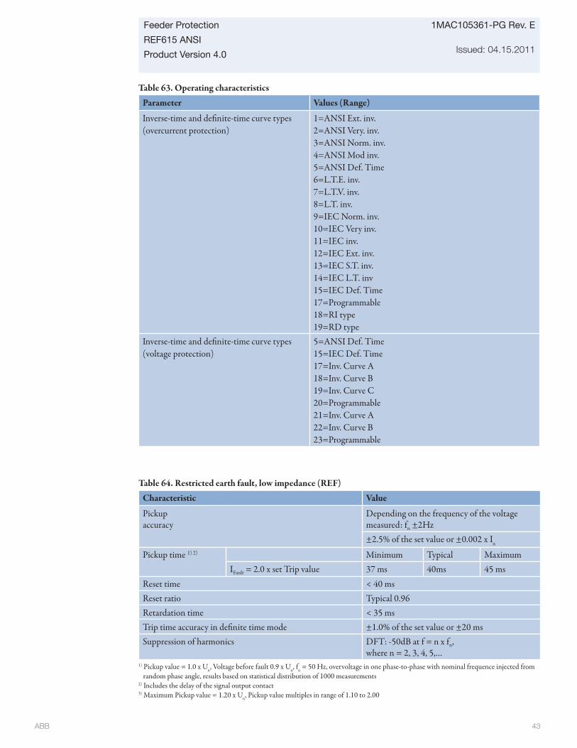
ABB 43
Feeder Protection
REF615 ANSI
Product Version 4.0
1MAC105361-PG Rev. E
Issued: 04.15.2011
Table 63. Operating characteristics
Parameter Values (Range)
Inverse-time and defi nite-time curve types (overcurrent protection)
1=ANSI Ext. inv.2=ANSI Very. inv.3=ANSI Norm. inv.4=ANSI Mod inv.5=ANSI Def. Time6=L.T.E. inv.7=L.T.V. inv.8=L.T. inv.9=IEC Norm. inv.10=IEC Very inv.11=IEC inv.12=IEC Ext. inv.13=IEC S.T. inv.14=IEC L.T. inv15=IEC Def. Time17=Programmable18=RI type19=RD type
Inverse-time and defi nite-time curve types (voltage protection)
5=ANSI Def. Time15=IEC Def. Time17=Inv. Curve A18=Inv. Curve B19=Inv. Curve C20=Programmable 21=Inv. Curve A22=Inv. Curve B23=Programmable
Table 64. Restricted earth fault, low impedance (REF)
Characteristic Value
Pickup accuracy
Depending on the frequency of the voltage measured: fn ±2Hz±2.5% of the set value or ±0.002 x In
Pickup time 1) 2) Minimum Typical MaximumIFault = 2.0 x set Trip value 37 ms 40ms 45 ms
Reset time < 40 msReset ratio Typical 0.96Retardation time < 35 msTrip time accuracy in defi nite time mode ±1.0% of the set value or ±20 msSuppression of harmonics DFT: -50dB at f = n x fn,
where n = 2, 3, 4, 5,…1) Pickup value = 1.0 x Un, Voltage before fault 0.9 x Un, fn = 50 Hz, overvoltage in one phase-to-phase with nominal frequence injected from
random phase angle, results based on statistical distribution of 1000 measurements2) Includes the delay of the signal output contact3) Maximum Pickup value = 1.20 x Un, Pickup value multiples in range of 1.10 to 2.00
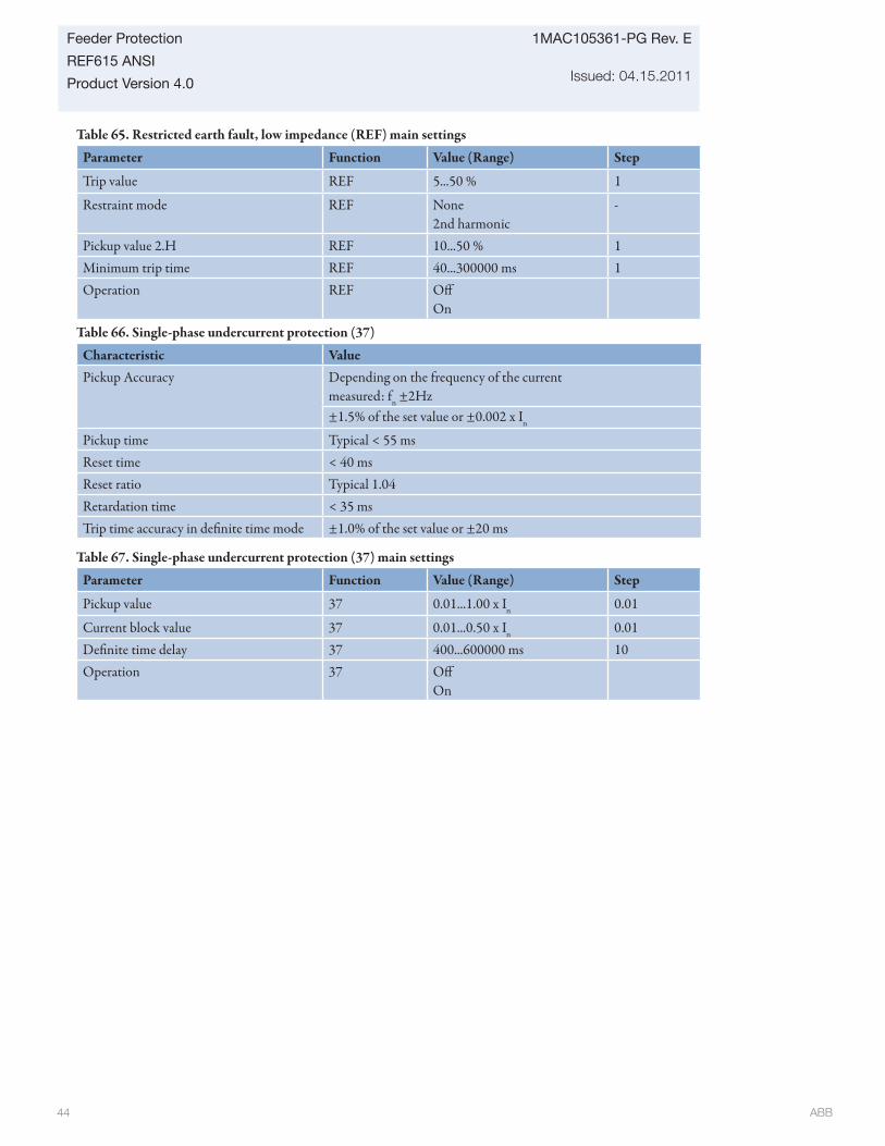
ABB 44
1MAC105361-PG Rev. E
Issued: 04.15.2011
Feeder Protection
REF615 ANSI
Product Version 4.0
Table 65. Restricted earth fault, low impedance (REF) main settings
Parameter Function Value (Range) Step
Trip value REF 5...50 % 1
Restraint mode REF None2nd harmonic
-
Pickup value 2.H REF 10...50 % 1Minimum trip time REF 40...300000 ms 1Operation REF Off
On
Table 67. Single-phase undercurrent protection (37) main settings
Parameter Function Value (Range) Step
Pickup value 37 0.01...1.00 x In 0.01
Current block value 37 0.01...0.50 x In 0.01Defi nite time delay 37 400...600000 ms 10Operation 37 Off
On
Table 66. Single-phase undercurrent protection (37)
Characteristic ValuePickup Accuracy Depending on the frequency of the current
measured: fn ±2Hz±1.5% of the set value or ±0.002 x In
Pickup time Typical < 55 msReset time < 40 msReset ratio Typical 1.04Retardation time < 35 msTrip time accuracy in defi nite time mode ±1.0% of the set value or ±20 ms
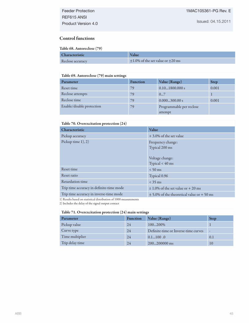
ABB 45
Feeder Protection
REF615 ANSI
Product Version 4.0
1MAC105361-PG Rev. E
Issued: 04.15.2011
Control functions
Table 68. Autoreclose (79)
Characteristic ValueReclose accuracy ±1.0% of the set value or ±20 ms
Table 69. Autoreclose (79) main settingsParameter Function Value (Range) StepReset time 79 0.10...1800.000 s 0.001Reclose attempts 79 0...7 1Reclose time 79 0.000...300.00 s 0.001Enable/disable protection 79 Programmable per reclose
attempt
Table 70. Overexcitation protection (24)Characteristic Value Pickup accuracy + 3.0% of the set valuePickup time 1), 2) Frequency change:
Typical 200 ms
Voltage change:Typical < 40 ms
Reset time < 50 msReset ratio Typical 0.96Retardation time < 35 msTrip time accuracy in defi nite-time mode ± 1.0% of the set value or + 20 msTrip time accuracy in inverse-time mode ± 5.0% of the theoretical value or + 50 ms
Table 71. Overexcitation protection (24) main settingsParameter Function Value (Range) StepPickup value 24 100...200% 1Curve type 24 Defi nite-time or Inverse-time curves -Time multiplier 24 0.1...100 .0 0.1Trip delay time 24 200...200000 ms 10
1) Results based on statistical distribution of 1000 measurements2) Includes the delay of the signal output contact
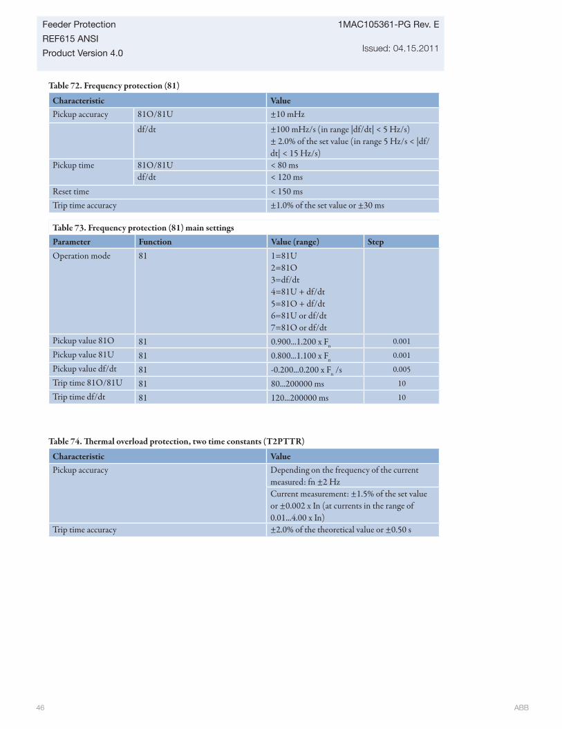
ABB 46
1MAC105361-PG Rev. E
Issued: 04.15.2011
Feeder Protection
REF615 ANSI
Product Version 4.0
Table 72. Frequency protection (81)
Characteristic ValuePickup accuracy 81O/81U ±10 mHz
df/dt ±100 mHz/s (in range |df/dt| < 5 Hz/s)± 2.0% of the set value (in range 5 Hz/s < |df/dt| < 15 Hz/s)
Pickup time 81O/81U < 80 msdf/dt < 120 ms
Reset time < 150 msTrip time accuracy ±1.0% of the set value or ±30 ms
Table 73. Frequency protection (81) main settingsParameter Function Value (range) StepOperation mode 81 1=81U
2=81O3=df/dt4=81U + df/dt5=81O + df/dt6=81U or df/dt7=81O or df/dt
Pickup value 81O 81 0.900...1.200 x Fn0.001
Pickup value 81U 81 0.800...1.100 x Fn0.001
Pickup value df/dt 81 -0.200...0.200 x Fn /s 0.005
Trip time 81O/81U 81 80...200000 ms 10
Trip time df/dt 81 120...200000 ms 10
Table 74. Th ermal overload protection, two time constants (T2PTTR)
Characteristic ValuePickup accuracy Depending on the frequency of the current
measured: fn ±2 HzCurrent measurement: ±1.5% of the set valueor ±0.002 x In (at currents in the range of0.01...4.00 x In)
Trip time accuracy ±2.0% of the theoretical value or ±0.50 s
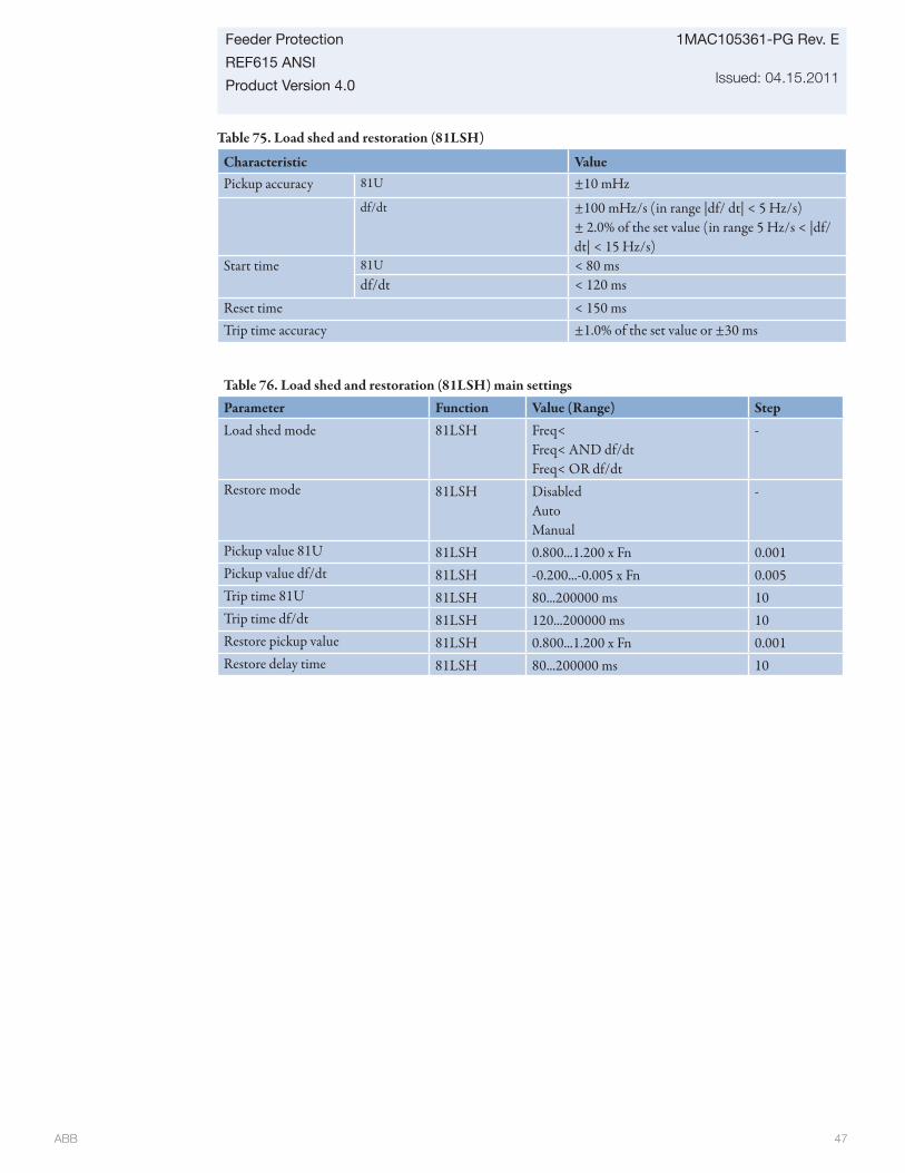
ABB 47
Feeder Protection
REF615 ANSI
Product Version 4.0
1MAC105361-PG Rev. E
Issued: 04.15.2011
Table 75. Load shed and restoration (81LSH)
Characteristic ValuePickup accuracy 81U ±10 mHz
df/dt ±100 mHz/s (in range |df/ dt| < 5 Hz/s)± 2.0% of the set value (in range 5 Hz/s < |df/dt| < 15 Hz/s)
Start time 81U < 80 msdf/dt < 120 ms
Reset time < 150 msTrip time accuracy ±1.0% of the set value or ±30 ms
Table 76. Load shed and restoration (81LSH) main settingsParameter Function Value (Range) StepLoad shed mode 81LSH Freq<
Freq< AND df/dtFreq< OR df/dt
-
Restore mode 81LSH DisabledAutoManual
-
Pickup value 81U 81LSH 0.800...1.200 x Fn 0.001Pickup value df/dt 81LSH -0.200...-0.005 x Fn 0.005Trip time 81U 81LSH 80...200000 ms 10Trip time df/dt 81LSH 120...200000 ms 10Restore pickup value 81LSH 0.800...1.200 x Fn 0.001Restore delay time 81LSH 80...200000 ms 10
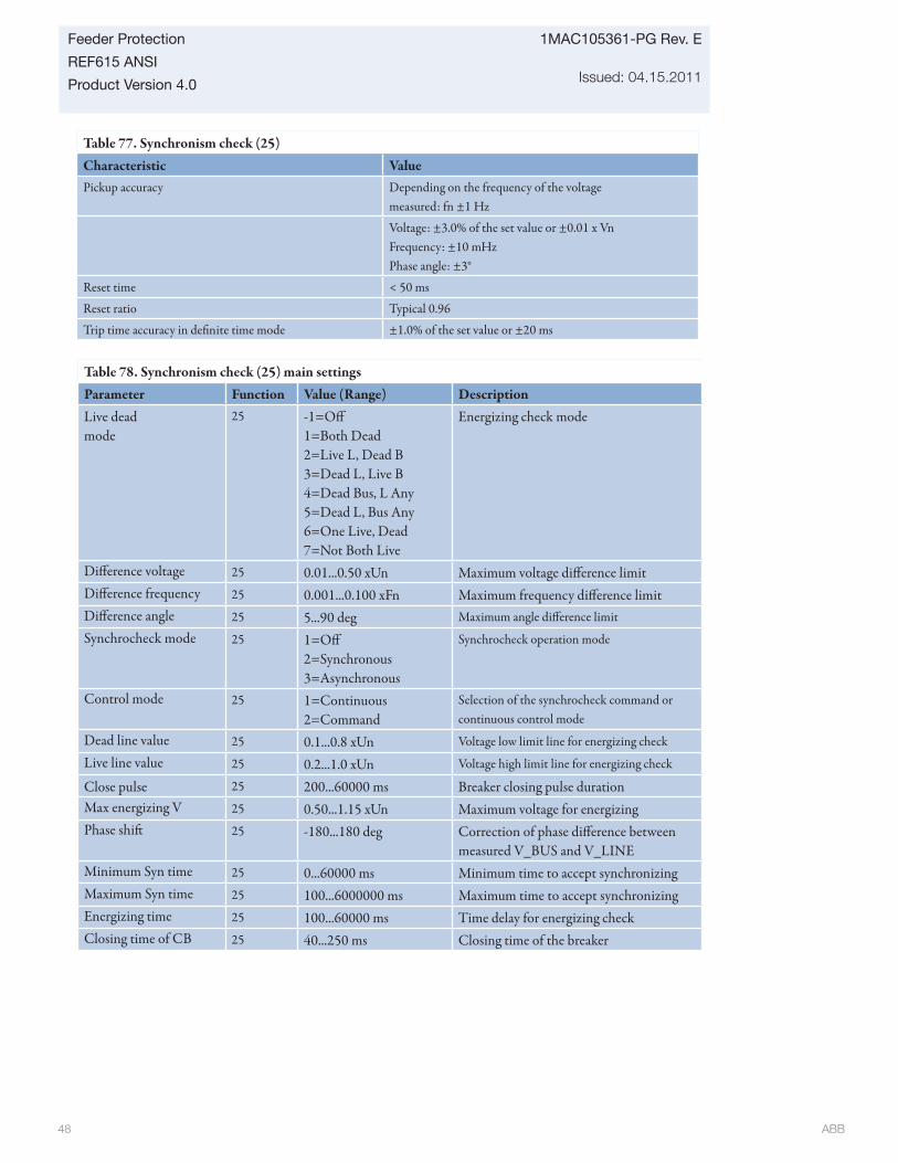
ABB 48
1MAC105361-PG Rev. E
Issued: 04.15.2011
Feeder Protection
REF615 ANSI
Product Version 4.0
Table 77. Synchronism check (25)Characteristic ValuePickup accuracy Depending on the frequency of the voltage
measured: fn ±1 Hz
Voltage: ±3.0% of the set value or ±0.01 x VnFrequency: ±10 mHzPhase angle: ±3°
Reset time < 50 ms
Reset ratio Typical 0.96
Trip time accuracy in defi nite time mode ±1.0% of the set value or ±20 ms
Table 78. Synchronism check (25) main settingsParameter Function Value (Range) DescriptionLive deadmode
25 -1=Off 1=Both Dead2=Live L, Dead B3=Dead L, Live B4=Dead Bus, L Any5=Dead L, Bus Any6=One Live, Dead7=Not Both Live
Energizing check mode
Diff erence voltage 25 0.01...0.50 xUn Maximum voltage diff erence limitDiff erence frequency 25 0.001...0.100 xFn Maximum frequency diff erence limitDiff erence angle 25 5...90 deg Maximum angle diff erence limit
Synchrocheck mode 25 1=Off 2=Synchronous3=Asynchronous
Synchrocheck operation mode
Control mode 25 1=Continuous2=Command
Selection of the synchrocheck command or continuous control mode
Dead line value 25 0.1...0.8 xUn Voltage low limit line for energizing check
Live line value 25 0.2...1.0 xUn Voltage high limit line for energizing check
Close pulse 25 200...60000 ms Breaker closing pulse durationMax energizing V 25 0.50...1.15 xUn Maximum voltage for energizingPhase shift 25 -180...180 deg Correction of phase diff erence between
measured V_BUS and V_LINEMinimum Syn time 25 0...60000 ms Minimum time to accept synchronizingMaximum Syn time 25 100...6000000 ms Maximum time to accept synchronizingEnergizing time 25 100...60000 ms Time delay for energizing checkClosing time of CB 25 40...250 ms Closing time of the breaker
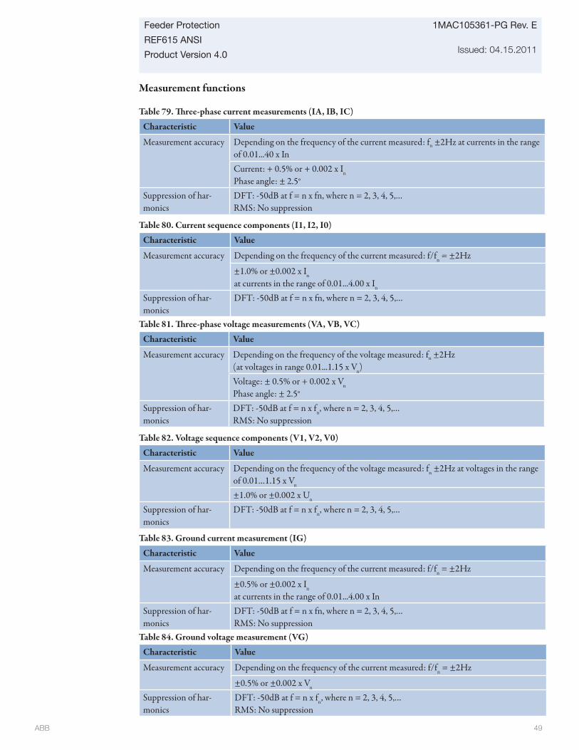
ABB 49
Feeder Protection
REF615 ANSI
Product Version 4.0
1MAC105361-PG Rev. E
Issued: 04.15.2011
Measurement functions
Table 79. Th ree-phase current measurements (IA, IB, IC)
Characteristic Value
Measurement accuracy Depending on the frequency of the current measured: fn ±2Hz at currents in the range of 0.01...40 x InCurrent: + 0.5% or + 0.002 x In
Phase angle: ± 2.5°
Suppression of har-monics
DFT: -50dB at f = n x fn, where n = 2, 3, 4, 5,…RMS: No suppression
Table 81. Th ree-phase voltage measurements (VA, VB, VC)
Characteristic Value
Measurement accuracy Depending on the frequency of the voltage measured: fn ±2Hz(at voltages in range 0.01...1.15 x Vn) Voltage: ± 0.5% or + 0.002 x Vn
Phase angle: ± 2.5°
Suppression of har-monics
DFT: -50dB at f = n x fn, where n = 2, 3, 4, 5,…RMS: No suppression
Table 80. Current sequence components (I1, I2, I0)
Characteristic Value
Measurement accuracy Depending on the frequency of the current measured: f/fn = ±2Hz
±1.0% or ±0.002 x In
at currents in the range of 0.01...4.00 x In
Suppression of har-monics
DFT: -50dB at f = n x fn, where n = 2, 3, 4, 5,…
Table 82. Voltage sequence components (V1, V2, V0)
Characteristic Value
Measurement accuracy Depending on the frequency of the voltage measured: fn ±2Hz at voltages in the range of 0.01…1.15 x Vn
±1.0% or ±0.002 x Un
Suppression of har-monics
DFT: -50dB at f = n x fn, where n = 2, 3, 4, 5,…
Table 83. Ground current measurement (IG)
Characteristic Value
Measurement accuracy Depending on the frequency of the current measured: f/fn = ±2Hz
±0.5% or ±0.002 x In
at currents in the range of 0.01...4.00 x InSuppression of har-monics
DFT: -50dB at f = n x fn, where n = 2, 3, 4, 5,…RMS: No suppression
Table 84. Ground voltage measurement (VG)
Characteristic Value
Measurement accuracy Depending on the frequency of the current measured: f/fn = ±2Hz
±0.5% or ±0.002 x Vn
Suppression of har-monics
DFT: -50dB at f = n x fn, where n = 2, 3, 4, 5,…RMS: No suppression
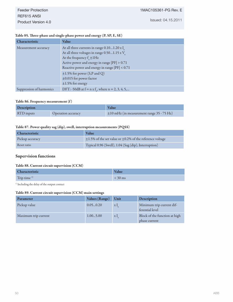
ABB 50
1MAC105361-PG Rev. E
Issued: 04.15.2011
Feeder Protection
REF615 ANSI
Product Version 4.0
Supervision functions
Table 88. Current circuit supervision (CCM)
Characteristic Value
Trip time 1) < 30 ms1) Including the delay of the output contact
Table 89. Current circuit supervision (CCM) main settings
Parameter Values (Range) Unit Description
Pickup value 0.05...0.20 x In Minimum trip current dif-ferential level
Maximum trip current 1.00...5.00 x In Block of the function at high phase current
Table 85. Th ree-phase and single-phase power and energy (P, SP, E, SE)
Characteristic Value
Measurement accuracy At all three currents in range 0.10…1.20 x In
At all three voltages in range 0.50…1.15 x Vn At the frequency fn ±1HzActive power and energy in range |PF| > 0.71Reactive power and energy in range |PF| < 0.71±1.5% for power (S,P and Q)±0.015 for power factor±1.5% for energy
Suppression of harmonics DFT: -50dB at f = n x fn, where n = 2, 3, 4, 5,…
Table 86. Frequency measurement (f )
Description ValueRTD inputs Operation accuracy ±10 mHz (in measurement range 35 - 75 Hz)
Table 87. Power quality sag (dip), swell, interruption measurements (PQSS)
Characteristic ValuePickup accuracy ±1.5% of the set value or ±0.2% of the reference voltage
Reset ratio Typical 0.96 (Swell), 1.04 (Sag (dip), Interruption)
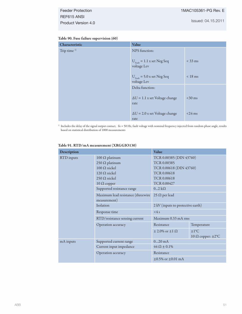
ABB 51
Feeder Protection
REF615 ANSI
Product Version 4.0
1MAC105361-PG Rev. E
Issued: 04.15.2011
Table 90. Fuse failure supervision (60)
Characteristic ValueTrip time 1) NPS function:
UFault = 1.1 x set Neg Seq voltage Lev
UFault = 5.0 x set Neg Seq voltage Lev
< 33 ms
< 18 ms
Delta function:
ΔU = 1.1 x set Voltage change rate
ΔU = 2.0 x set Voltage change rate
<30 ms
<24 ms
1) Includes the delay of the signal output contact, fn = 50 Hz, fault voltage with nominal frequency injected from random phase angle, results based on statistical distribution of 1000 measurements
Table 91. RTD/mA measurement (XRGGIO130)
Description ValueRTD inputs 100 Ω platinum
250 Ω platinum100 Ω nickel120 Ω nickel250 Ω nickel10 Ω copper
TCR 0.00385 (DIN 43760)TCR 0.00385TCR 0.00618 (DIN 43760)TCR 0.00618TCR 0.00618TCR 0.00427
Supported resistance range 0...2 kΩ
Maximum lead resistance (threewire measurement)
25 Ω per lead
Isolation 2 kV (inputs to protective earth)
Response time <4 s
RTD/resistance sensing current Maximum 0.33 mA rms
Operation accuracy Resistance Temperature
± 2.0% or ±1 Ω ±1°C10 Ω copper: ±2°C
mA inputs Supported current range 0…20 mACurrent input impedance 44 Ω ± 0.1%Operation accuracy Resistance
±0.5% or ±0.01 mA
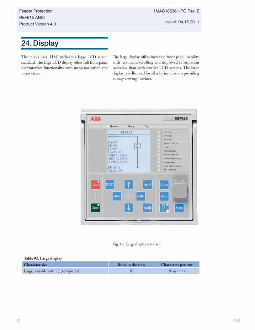
ABB 52
1MAC105361-PG Rev. E
Issued: 04.15.2011
Feeder Protection
REF615 ANSI
Product Version 4.0
24. Display
The relay’s local HMI includes a large LCD screen standard. Th e large LCD display off ers full front-panel user-interface functionality with menu navigation and menu views.
Th e large display off ers increased front-panel usability with less menu scrolling and improved information overview than with smaller LCD screens. The large display is well-suited for all relay installations providing an easy viewing interface.
Fig. 17: Large display standard
Table 92. Large displayCharacter size Rows in the view Characters per rowLarge, variable width (13x14pixels) 10 20 or more
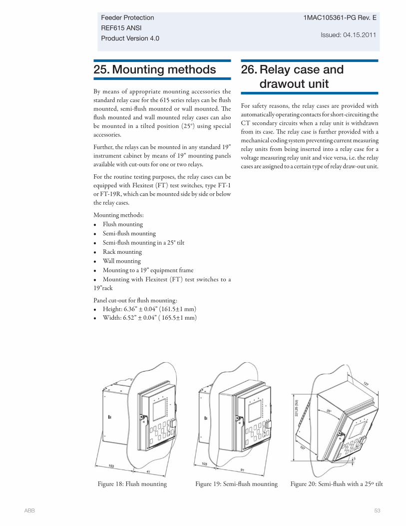
ABB 53
Feeder Protection
REF615 ANSI
Product Version 4.0
1MAC105361-PG Rev. E
Issued: 04.15.2011
25. Mounting methods
By means of appropriate mounting accessories the standard relay case for the 615 series relays can be fl ush mounted, semi-fl ush mounted or wall mounted. Th e fl ush mounted and wall mounted relay cases can also be mounted in a tilted position (25°) using special accessories.
Further, the relays can be mounted in any standard 19” instrument cabinet by means of 19” mounting panels available with cut-outs for one or two relays.
For the routine testing purposes, the relay cases can be equipped with Flexitest (FT) test switches, type FT-1 or FT-19R, which can be mounted side by side or below the relay cases.
Mounting methods:• Flush mounting• Semi-fl ush mounting• Semi-fl ush mounting in a 25° tilt• Rack mounting• Wall mounting• Mounting to a 19” equipment frame• Mounting with Flexitest (FT) test switches to a 19”rack
Panel cut-out for fl ush mounting: • Height: 6.36” ± 0.04” (161.5±1 mm)• Width: 6.52” ± 0.04” ( 165.5±1 mm)
26. Relay case and drawout unit
For safety reasons, the relay cases are provided with automatically operating contacts for short-circuiting the CT secondary circuits when a relay unit is withdrawn from its case. Th e relay case is further provided with a mechanical coding system preventing current measuring relay units from being inserted into a relay case for a voltage measuring relay unit and vice versa, i.e. the relay cases are assigned to a certain type of relay draw-out unit.
Figure 18: Flush mounting Figure 19: Semi-fl ush mounting Figure 20: Semi-fl ush with a 25º tilt
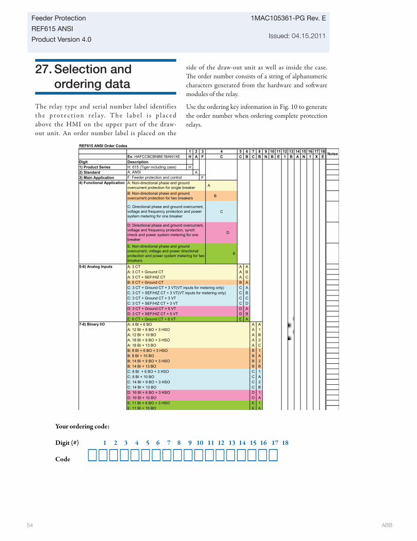
ABB 54
1MAC105361-PG Rev. E
Issued: 04.15.2011
Feeder Protection
REF615 ANSI
Product Version 4.0
27. Selection and ordering data
The relay type and serial number label identifies t h e p r o t e c t i o n r e l a y. T h e l a b e l i s p l a c e d above the HMI on the upper part of the draw-out unit. An order number label is placed on the
side of the draw-out unit as well as inside the case. Th e order number consists of a string of alphanumeric characters generated from the hardware and soft ware modules of the relay.
Use the ordering key information in Fig. 10 to generate the order number when ordering complete protection relays.
Your ordering code:
Digit (#) 1 2 3 4 5 6 7 8 9 10 11 12 13 14 15 16 17 18
Code
REF615 ANSI Order Codes1 2 3 5 6 7 8 9 10 11 12 13 14 15 16 17 18
Ex: HAFCCBCBNBE1BAN1XE H A F C B C B N B E 1 B A N 1 X EDigit Description1) Product Series H: 615 (Tiger including case) H2) Standard A3) Main Application F
A
B
C
D
E
A: 3 CT A AA: 3 CT + Ground CT A BA: 3 CT + SEF/HIZ CT A CB: 6 CT + Ground CT B AC: 3 CT + Ground CT + 3 VT(VT inputs for metering only) C AC: 3 CT + SEF/HIZ CT + 3 VT(VT inputs for metering only) C BC: 3 CT + Ground CT + 3 VT C CC: 3 CT + SEF/HIZ CT + 3 VT C DD: 3 CT + Ground CT + 5 VT D AD: 3 CT + SEF/HIZ CT + 5 VT D BE: 6 CT + Ground CT + 6 VT E AA: 4 BI + 6 BO A AA: 12 BI + 6 BO + 3 HSO A 1A: 12 BI + 10 BO A BA: 18 BI + 9 BO + 3 HSO A 2A: 18 BI + 13 BO A CB: 8 BI + 6 BO + 3 HSO B 1B: 8 BI + 10 BO B AB: 14 BI + 9 BO + 3 HSO B 2B: 14 BI + 13 BO B BC: 8 BI + 6 BO + 3 HSO C 1C: 8 BI + 10 BO C AC: 14 BI + 9 BO + 3 HSO C 2C: 14 BI + 13 BO C BD: 16 BI + 6 BO + 3 HSO D 1D: 16 BI + 10 BO D AE: 11 BI + 6 BO + 3 HSO E 1E: 11 BI + 10 BO E A
4C
C: Directional phase and ground overcurrent, voltage and frequency protection and power system metering for one breaker
D: Directional phase and ground overcurrent, voltage and frequency protection, synch check and power system metering for one breaker
E: Non-directional phase and ground overcurrent, voltage and power directional protection and power system metering for two breakers
Notes
F: Feeder protection and controlA: ANSI
B: Non-directional phase and ground overcurrent protection for two breakers
4) Functional Application
5-6) Analog Inputs
7-8) Binary I/O
A: Non-directional phase and ground overcurrent protection for single breaker
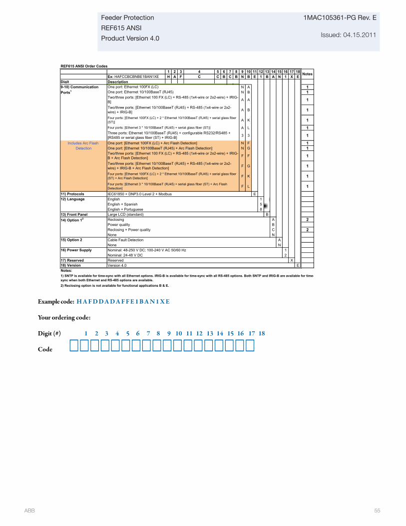
ABB 55
Feeder Protection
REF615 ANSI
Product Version 4.0
1MAC105361-PG Rev. E
Issued: 04.15.2011
Example code: H A F D D A D A F F E 1 B A N 1 X E
Your ordering code:
Digit (#) 1 2 3 4 5 6 7 8 9 10 11 12 13 14 15 16 17 18
Code
REF615 ANSI Order Codes1 2 3 5 6 7 8 9 10 11 12 13 14 15 16 17 18
Ex: HAFCCBCBNBE1BAN1XE H A F C B C B N B E 1 B A N 1 X EDigit Description
4C
Notes
N A 1N B 1
A A 1
A B 1
A K 1
A L 1
3 3 1
Includes Arc Flash One port: [Ethernet 100FX (LC) + Arc Flash Detection] N F 1Detection One port: [Ethernet 10/100BaseT (RJ45) + Arc Flash Detection] N G 1
F F 1
F G 1
F K 1
F L 1
11) Protocols IEC61850 + DNP3.0 Level 2 + Modbus EEnglish 1English + Spanish 5English + Portuguese 8
13) Front Panel Large LCD (standard) BReclosing A 2Power quality BReclosing + Power quality C 2None NCable Fault Detection ANone NNominal: 48-250 V DC; 100-240 V AC 50/60 Hz 1Nominal: 24-48 V DC 2
17) Reserved Reserved X18) Version Version 4.0 ENotes:1) SNTP is available for time-sync with all Ethernet options. IRIG-B is available for time-sync with all RS-485 options. Both SNTP and IRIG-B are available for time-sync when both Ethernet and RS-485 options are available.2) Reclosing option is not available for functional applications B & E.
Four ports: [Ethernet 3 * 10/100BaseT (RJ45) + serial glass fiber (ST)]Three ports: Ethernet 10/100BaseT (RJ45) + configurable RS232/RS485 + [RS485 or serial glass fiber (ST) + IRIG-B]
One port: Ethernet 100FX (LC)One port: Ethernet 10/100BaseT (RJ45)Two/three ports: [Ethernet 100 FX (LC) + RS-485 (1x4-wire or 2x2-wire) + IRIG-B]
16) Power Supply
9-10) Communication Ports1
12) Language
14) Option 12
15) Option 2
Two/three ports: [Ethernet 100 FX (LC) + RS-485 (1x4-wire or 2x2-wire) + IRIG-B + Arc Flash Detection]
Four ports: [Ethernet 3 * 10/100BaseT (RJ45) + serial glass fiber (ST) + Arc Flash Detection]
Four ports: [Ethernet 100FX (LC) + 2 * Ethernet 10/100BaseT (RJ45) + serial glass fiber (ST) + Arc Flash Detection]
Two/three ports: [Ethernet 10/100BaseT (RJ45) + RS-485 (1x4-wire or 2x2-wire) + IRIG-B + Arc Flash Detection]
Two/three ports: [Ethernet 10/100BaseT (RJ45) + RS-485 (1x4-wire or 2x2-wire) + IRIG-B]Four ports: [Ethernet 100FX (LC) + 2 * Ethernet 10/100BaseT (RJ45) + serial glass fiber (ST)]
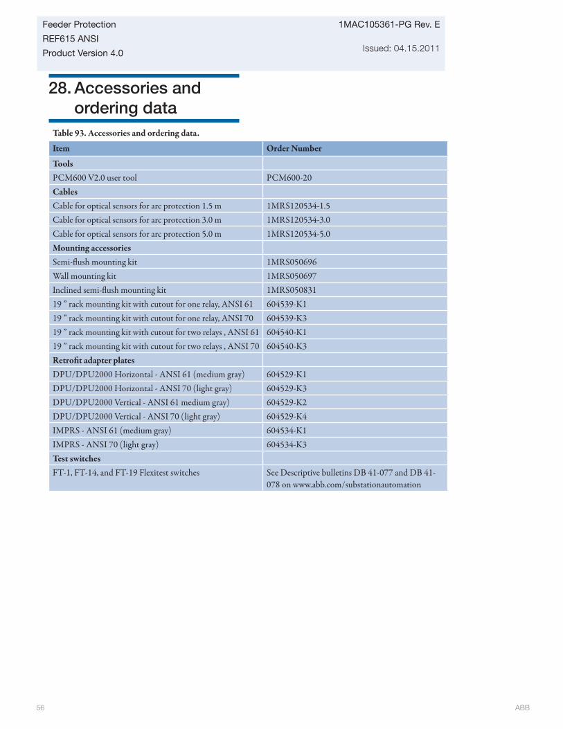
ABB 56
1MAC105361-PG Rev. E
Issued: 04.15.2011
Feeder Protection
REF615 ANSI
Product Version 4.0
28. Accessories and ordering data
Table 93. Accessories and ordering data.
Item Order Number
Tools PCM600 V2.0 user tool PCM600-20CablesCable for optical sensors for arc protection 1.5 m 1MRS120534-1.5Cable for optical sensors for arc protection 3.0 m 1MRS120534-3.0Cable for optical sensors for arc protection 5.0 m 1MRS120534-5.0Mounting accessoriesSemi-fl ush mounting kit 1MRS050696Wall mounting kit 1MRS050697Inclined semi-fl ush mounting kit 1MRS05083119 ” rack mounting kit with cutout for one relay, ANSI 61 604539-K119 ” rack mounting kit with cutout for one relay, ANSI 70 604539-K319 ” rack mounting kit with cutout for two relays , ANSI 61 604540-K119 ” rack mounting kit with cutout for two relays , ANSI 70 604540-K3Retrofi t adapter platesDPU/DPU2000 Horizontal - ANSI 61 (medium gray) 604529-K1DPU/DPU2000 Horizontal - ANSI 70 (light gray) 604529-K3DPU/DPU2000 Vertical - ANSI 61 medium gray) 604529-K2DPU/DPU2000 Vertical - ANSI 70 (light gray) 604529-K4IMPRS - ANSI 61 (medium gray) 604534-K1IMPRS - ANSI 70 (light gray) 604534-K3Test switchesFT-1, FT-14, and FT-19 Flexitest switches See Descriptive bulletins DB 41-077 and DB 41-
078 on www.abb.com/substationautomation
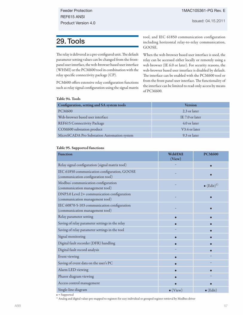
ABB 57
Feeder Protection
REF615 ANSI
Product Version 4.0
1MAC105361-PG Rev. E
Issued: 04.15.2011
29. Tools
Th e relay is delivered as a pre-confi gured unit. Th e default parameter setting values can be changed from the front-panel user interface, the web-browser based user interface (WHMI) or the PCM600 tool in combination with the relay specifi c connectivity package (CP).
PCM600 off ers extensive relay confi guration functions such as relay signal confi guration using the signal matrix
tool, and IEC 61850 communication configuration including horizontal relay-to-relay communication, GOOSE.
When the web-browser based user interface is used, the relay can be accessed either locally or remotely using a web browser (IE 6.0 or later). For security reasons, the web-browser based user interface is disabled by default. Th e interface can be enabled with the PCM600 tool or from the front panel user interface. Th e functionality of the interface can be limited to read-only access by means of PCM600.
Confi guration, setting and SA system tools VersionPCM600 2.3 or laterWeb-browser based user interface IE 7.0 or laterREF615 Connectivity Package 4.0 or laterCOM600 substation product V3.4 or laterMicroSCADA Pro Substation Automation system 9.3 or later
Table 94. Tools
Table 95. Supported functions
Function WebHMI(View)
PCM600
Relay signal confi guration (signal matrix tool) - •IEC 61850 communication confi guration, GOOSE(communication confi guration tool)
- •
Modbus® communication confi guration(communication management tool)
- • (Edit)1)
DNP3.0 Level 2+ communication confi guration (communication management tool) - •
IEC 60870-5-103 communication confi guration(communication management tool) - •
Relay parameter setting • •Saving of relay parameter settings in the relay • •Saving of relay parameter settings in the tool - •Signal monitoring • •Digital fault recorder (DFR) handling • •Digital fault record analysis - •Event viewing • -
Saving of event data on the user’s PC • -
Alarm LED viewing • •Phasor diagram viewing • -
Access control management • •Single-line diagram • (View) • (Edit)
• = Supported1) Analog and digital values pre-mapped to registers for easy individual or grouped register retrieval by Modbus driver
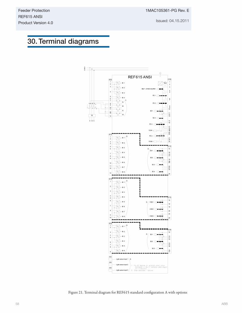
ABB 58
1MAC105361-PG Rev. E
Issued: 04.15.2011
Feeder Protection
REF615 ANSI
Product Version 4.0
30. Terminal diagrams
Figure 21. Terminal diagram for REF615 standard confi guration A with options
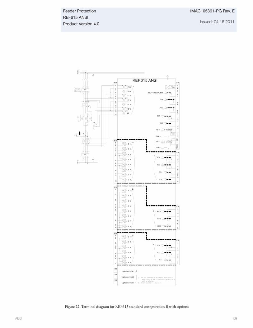
ABB 59
Feeder Protection
REF615 ANSI
Product Version 4.0
1MAC105361-PG Rev. E
Issued: 04.15.2011
Figure 22. Terminal diagram for REF615 standard confi guration B with options
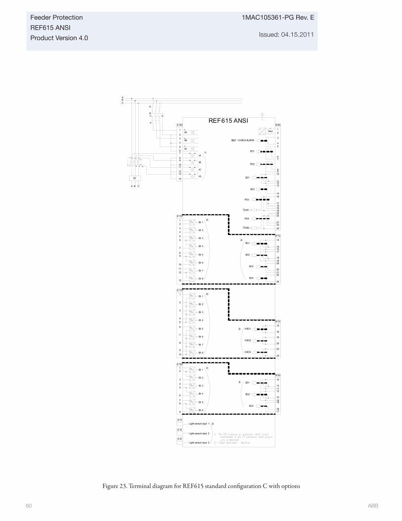
ABB 60
1MAC105361-PG Rev. E
Issued: 04.15.2011
Feeder Protection
REF615 ANSI
Product Version 4.0
Figure 23. Terminal diagram for REF615 standard confi guration C with options
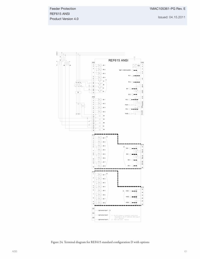
ABB 61
Feeder Protection
REF615 ANSI
Product Version 4.0
1MAC105361-PG Rev. E
Issued: 04.15.2011
Figure 24. Terminal diagram for REF615 standard confi guration D with options
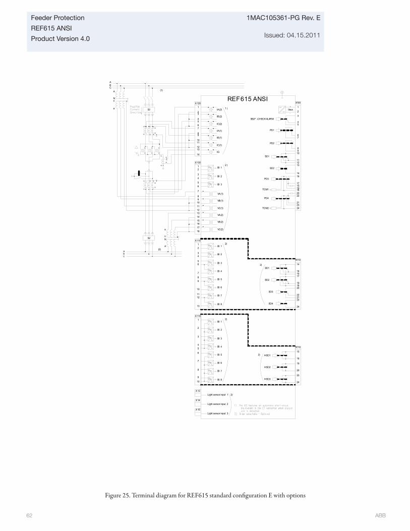
ABB 62
1MAC105361-PG Rev. E
Issued: 04.15.2011
Feeder Protection
REF615 ANSI
Product Version 4.0
Figure 25. Terminal diagram for REF615 standard confi guration E with options
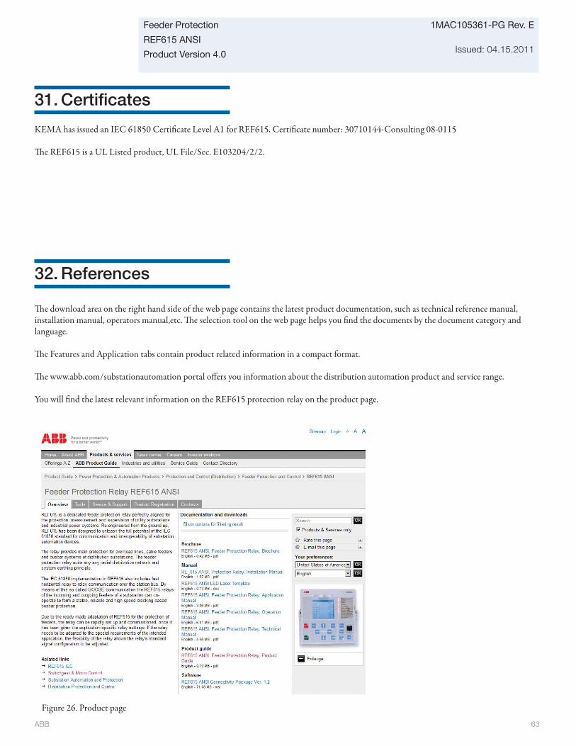
ABB 63
Feeder Protection
REF615 ANSI
Product Version 4.0
1MAC105361-PG Rev. E
Issued: 04.15.2011
31. Certifi cates
32. References
KEMA has issued an IEC 61850 Certifi cate Level A1 for REF615. Certifi cate number: 30710144-Consulting 08-0115
Th e REF615 is a UL Listed product, UL File/Sec. E103204/2/2.
Th e download area on the right hand side of the web page contains the latest product documentation, such as technical reference manual, installation manual, operators manual,etc. Th e selection tool on the web page helps you fi nd the documents by the document category and language.
Th e Features and Application tabs contain product related information in a compact format.
Th e www.abb.com/substationautomation portal off ers you information about the distribution automation product and service range.
You will fi nd the latest relevant information on the REF615 protection relay on the product page.
Figure 26. Product page
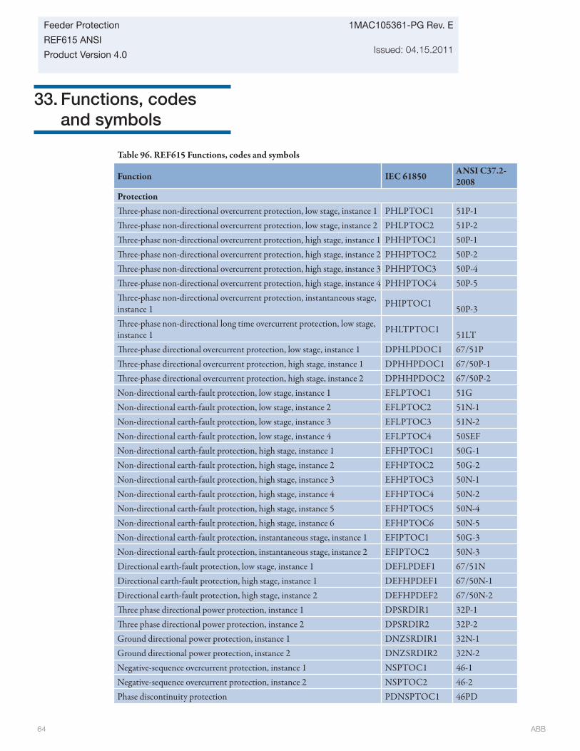
ABB 64
1MAC105361-PG Rev. E
Issued: 04.15.2011
Feeder Protection
REF615 ANSI
Product Version 4.0
33. Functions, codes and symbols
Table 96. REF615 Functions, codes and symbols
Function IEC 61850 ANSI C37.2-2008
ProtectionTh ree-phase non-directional overcurrent protection, low stage, instance 1 PHLPTOC1 51P-1Th ree-phase non-directional overcurrent protection, low stage, instance 2 PHLPTOC2 51P-2Th ree-phase non-directional overcurrent protection, high stage, instance 1 PHHPTOC1 50P-1Th ree-phase non-directional overcurrent protection, high stage, instance 2 PHHPTOC2 50P-2Th ree-phase non-directional overcurrent protection, high stage, instance 3 PHHPTOC3 50P-4Th ree-phase non-directional overcurrent protection, high stage, instance 4 PHHPTOC4 50P-5Th ree-phase non-directional overcurrent protection, instantaneous stage, instance 1 PHIPTOC1 50P-3Th ree-phase non-directional long time overcurrent protection, low stage, instance 1 PHLTPTOC1 51LTTh ree-phase directional overcurrent protection, low stage, instance 1 DPHLPDOC1 67/51PTh ree-phase directional overcurrent protection, high stage, instance 1 DPHHPDOC1 67/50P-1Th ree-phase directional overcurrent protection, high stage, instance 2 DPHHPDOC2 67/50P-2Non-directional earth-fault protection, low stage, instance 1 EFLPTOC1 51GNon-directional earth-fault protection, low stage, instance 2 EFLPTOC2 51N-1Non-directional earth-fault protection, low stage, instance 3 EFLPTOC3 51N-2Non-directional earth-fault protection, low stage, instance 4 EFLPTOC4 50SEFNon-directional earth-fault protection, high stage, instance 1 EFHPTOC1 50G-1Non-directional earth-fault protection, high stage, instance 2 EFHPTOC2 50G-2Non-directional earth-fault protection, high stage, instance 3 EFHPTOC3 50N-1Non-directional earth-fault protection, high stage, instance 4 EFHPTOC4 50N-2Non-directional earth-fault protection, high stage, instance 5 EFHPTOC5 50N-4Non-directional earth-fault protection, high stage, instance 6 EFHPTOC6 50N-5Non-directional earth-fault protection, instantaneous stage, instance 1 EFIPTOC1 50G-3Non-directional earth-fault protection, instantaneous stage, instance 2 EFIPTOC2 50N-3Directional earth-fault protection, low stage, instance 1 DEFLPDEF1 67/51NDirectional earth-fault protection, high stage, instance 1 DEFHPDEF1 67/50N-1Directional earth-fault protection, high stage, instance 2 DEFHPDEF2 67/50N-2Th ree phase directional power protection, instance 1 DPSRDIR1 32P-1Th ree phase directional power protection, instance 2 DPSRDIR2 32P-2Ground directional power protection, instance 1 DNZSRDIR1 32N-1Ground directional power protection, instance 2 DNZSRDIR2 32N-2Negative-sequence overcurrent protection, instance 1 NSPTOC1 46-1Negative-sequence overcurrent protection, instance 2 NSPTOC2 46-2Phase discontinuity protection PDNSPTOC1 46PD
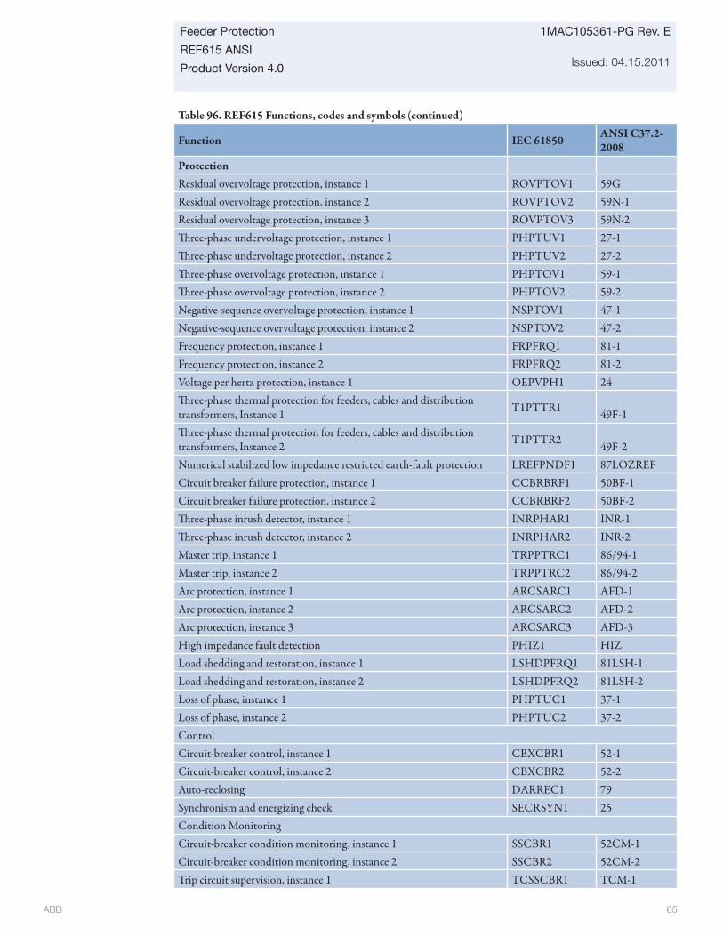
ABB 65
Feeder Protection
REF615 ANSI
Product Version 4.0
1MAC105361-PG Rev. E
Issued: 04.15.2011
Table 96. REF615 Functions, codes and symbols (continued)
Function IEC 61850 ANSI C37.2-2008
ProtectionResidual overvoltage protection, instance 1 ROVPTOV1 59G Residual overvoltage protection, instance 2 ROVPTOV2 59N-1Residual overvoltage protection, instance 3 ROVPTOV3 59N-2Th ree-phase undervoltage protection, instance 1 PHPTUV1 27-1Th ree-phase undervoltage protection, instance 2 PHPTUV2 27-2Th ree-phase overvoltage protection, instance 1 PHPTOV1 59-1Th ree-phase overvoltage protection, instance 2 PHPTOV2 59-2Negative-sequence overvoltage protection, instance 1 NSPTOV1 47-1Negative-sequence overvoltage protection, instance 2 NSPTOV2 47-2Frequency protection, instance 1 FRPFRQ1 81-1Frequency protection, instance 2 FRPFRQ2 81-2Voltage per hertz protection, instance 1 OEPVPH1 24Th ree-phase thermal protection for feeders, cables and distribution transformers, Instance 1 T1PTTR1 49F-1Th ree-phase thermal protection for feeders, cables and distribution transformers, Instance 2 T1PTTR2 49F-2Numerical stabilized low impedance restricted earth-fault protection LREFPNDF1 87LOZREFCircuit breaker failure protection, instance 1 CCBRBRF1 50BF-1Circuit breaker failure protection, instance 2 CCBRBRF2 50BF-2Th ree-phase inrush detector, instance 1 INRPHAR1 INR-1Th ree-phase inrush detector, instance 2 INRPHAR2 INR-2Master trip, instance 1 TRPPTRC1 86/94-1Master trip, instance 2 TRPPTRC2 86/94-2Arc protection, instance 1 ARCSARC1 AFD-1Arc protection, instance 2 ARCSARC2 AFD-2Arc protection, instance 3 ARCSARC3 AFD-3High impedance fault detection PHIZ1 HIZLoad shedding and restoration, instance 1 LSHDPFRQ1 81LSH-1Load shedding and restoration, instance 2 LSHDPFRQ2 81LSH-2Loss of phase, instance 1 PHPTUC1 37-1Loss of phase, instance 2 PHPTUC2 37-2ControlCircuit-breaker control, instance 1 CBXCBR1 52-1Circuit-breaker control, instance 2 CBXCBR2 52-2Auto-reclosing DARREC1 79Synchronism and energizing check SECRSYN1 25Condition MonitoringCircuit-breaker condition monitoring, instance 1 SSCBR1 52CM-1Circuit-breaker condition monitoring, instance 2 SSCBR2 52CM-2Trip circuit supervision, instance 1 TCSSCBR1 TCM-1
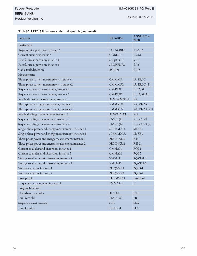
ABB 66
1MAC105361-PG Rev. E
Issued: 04.15.2011
Feeder Protection
REF615 ANSI
Product Version 4.0
Table 96. REF615 Functions, codes and symbols (continued)
Function IEC 61850 ANSI C37.2-2008
ProtectionTrip circuit supervision, instance 2 TCSSCBR2 TCM-2Current circuit supervision CCRDIF1 CCMFuse failure supervision, intance 1 SEQRFUF1 60-1Fuse failure supervision, intance 2 SEQRFUF2 60-2Cable fault detection RCFD1 CFDMeasurementTh ree-phase current measurement, instance 1 CMMXU1 IA, IB, ICTh ree-phase current measurement, instance 2 CMMXU2 IA, IB, IC (2)Sequence current measurement, instance 1 CSMSQI1 I1, I2, I0Sequence current measurement, instance 2 CSMSQI2 I1, I2, I0 (2)Residual current measurement, instance 1 RESCMMXU1 IGTh ree-phase voltage measurement, instance 1 VMMXU1 VA, VB, VCTh ree-phase voltage measurement, instance 2 VMMXU2 VA, VB, VC (2)Residual voltage measurement, instance 1 RESVMMXU1 VGSequence voltage measurement, instance 1 VSMSQI1 V1, V2, V0Sequence voltage measurement, instance 2 VSMSQI2 V1, V2, V0 (2)Single-phase power and energy measurement, instance 1 SPEMMXU1 SP, SE-1Single-phase power and energy measurement, instance 2 SPEMMXU2 SP, SE-2Th ree-phase power and energy measurement, instance 1 PEMMXU1 P, E-1Th ree-phase power and energy measurement, instance 2 PEMMXU2 P, E-2Current total demand distortion, instance 1 CMHAI1 PQI-1Current total demand distortion, instance 2 CMHAI2 PQI-2Voltage total harmonic distortion, instance 1 VMHAI1 PQVPH-1Voltage total harmonic distortion, instance 2 VMHAI2 PQVPH-2Voltage variation, instance 1 PHQVVR1 PQSS-1Voltage variation, instance 2 PHQVVR2 PQSS-2Load profi le LDPMSTA1 LoadProfFrequency measurement, instance 1 FMMXU1 fLogging functionsDisturbance recorder RDRE1 DFRFault recorder FLMSTA1 FRSequence event recorder SER SER
Fault location DRFLO1 FLO
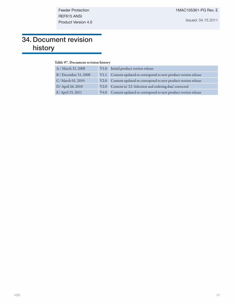
ABB 67
Feeder Protection
REF615 ANSI
Product Version 4.0
1MAC105361-PG Rev. E
Issued: 04.15.2011
34. Document revision history
Table 97. Document revision history
A / March 31, 2008 V1.0 Initial product version release
B / December 31, 2008 V1.1 Content updated to correspond to new product version releaseC/ March 01, 2010 V2.0 Content updated to correspond to new product version releaseD/ April 26, 2010 V2.0 Content in ‘23. Selection and ordering data’ correctedE/ April 15, 2011 V4.0 Content updated to correspond to new product version release
ABB Inc.Distribution Automation4300 Coral Ridge DriveCoral Springs, Florida 33065Phone: +1 954 752 6700Fax: +1 954 345 5329
www.abb.com/substationautomation
All sales are subject to ABB Inc.General Terms and Conditions of Sale.
While every effort has been made to assure accuracy, the information in this document is subject to change without notice.
© Copyright 2008, 2011 ABB Inc. All rights reserved.
Contact us
1MA
C10
5361
-PG R
ev E
Ap
ril 2
011
(rep
lace
s 1V
AD
3866
01-A
G)