Embed Size (px)
Citation preview
— A B B M E A SU R EM ENT & A N A LY TI C S | A RTI CLE
ABB Field Information Manager (FIM)Field device integration
ABB unveils extended FIM diagnostics with ABB’s EDP300 positioner valve maintenance UIP – FIM software version 1.1
Measurement made easy
Introduction
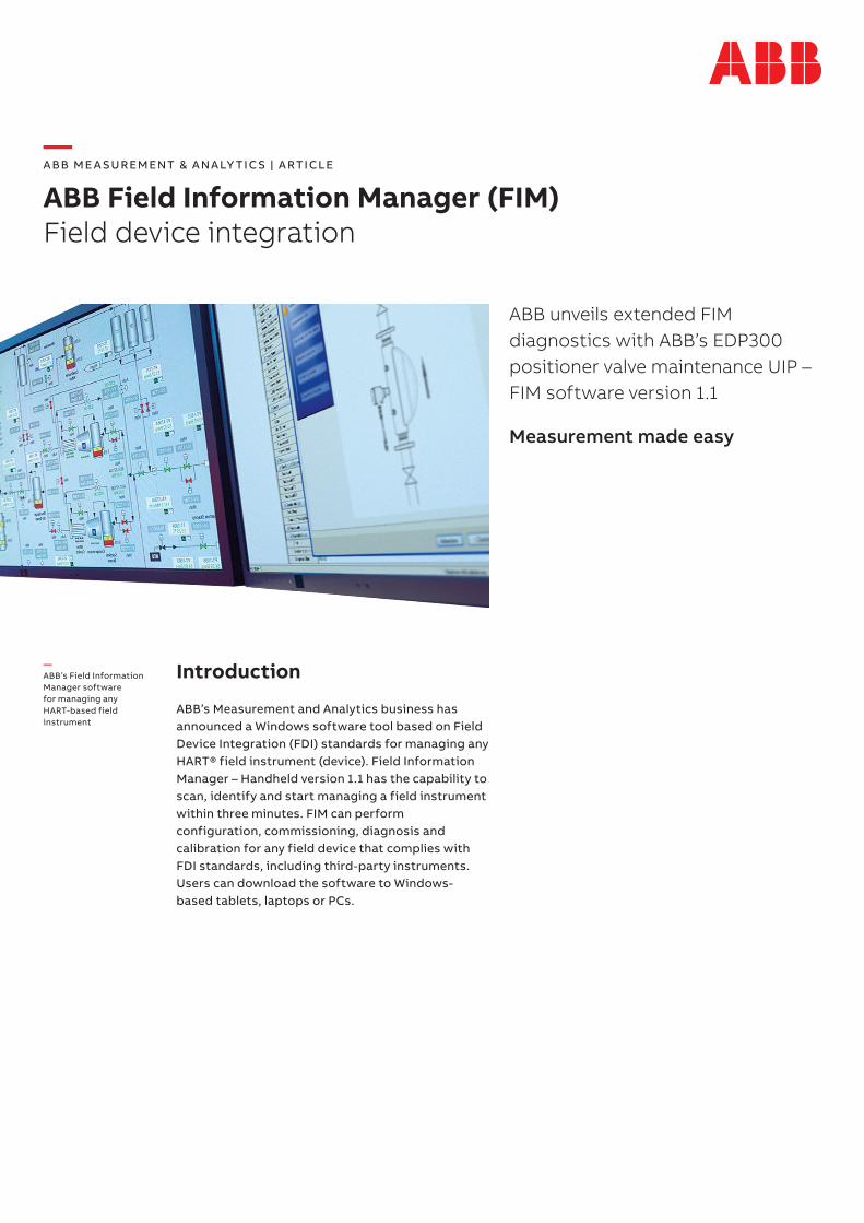
ABB’s Measurement and Analytics business has announced a Windows software tool based on Field Device Integration (FDI) standards for managing any HART® field instrument (device). Field Information Manager – Handheld version 1.1 has the capability to scan, identify and start managing a field instrument within three minutes. FIM can perform configuration, commissioning, diagnosis and calibration for any field device that complies with FDI standards, including third-party instruments. Users can download the software to Windows-based tablets, laptops or PCs.
—ABB’s Field Information Manager software for managing any HART-based field instrument
2 A B B F I E LD I N FO R M ATI O N M A N AG E R ( F I M ) | AT/M E A SU R EM ENT/0 0 6 - EN R E V. C
What is FDI?
The Fieldcomm Group, a non-profit global standards member organization devoted to connecting the world of process automation, has developed FDI technology and standards. This technology builds on accepted definitions of HART-based field instruments such as process instrumentation for measuring flow, pressure, temperature, and level, as well as for valve positioners.
The HART device definitions are performed using the text-based Electronic Device Description Language (EDDL). Most HART field instrumentation use 4 to 20 mA analog and digital communication defined by the specific EDDL. This language covers the various tasks needed to manage a field instrument over its lifecycle.
Until now, EDDL has competed with proprietary software-based technologies of the leading instrument manufacturers to manage these tasks. The FDI specification attempts to integrate the two technologies into one solution for field device management. Leading process instrumentation and control manufacturers, end users, universities and researchers are collaborating to develop FDI-based field instrument device management files for free user download.
Connecting FIM to HART devices
In 2015 ABB was the first company to provide an FDI-based software tool for managing HART field instrument – FIM 1.0. With the latest hand-held version users can download FIM software to Windows-based computers such as a tablet, laptop or PC. The computers can then easily replace proprietary handheld HART communication products for these field instrument management tasks.
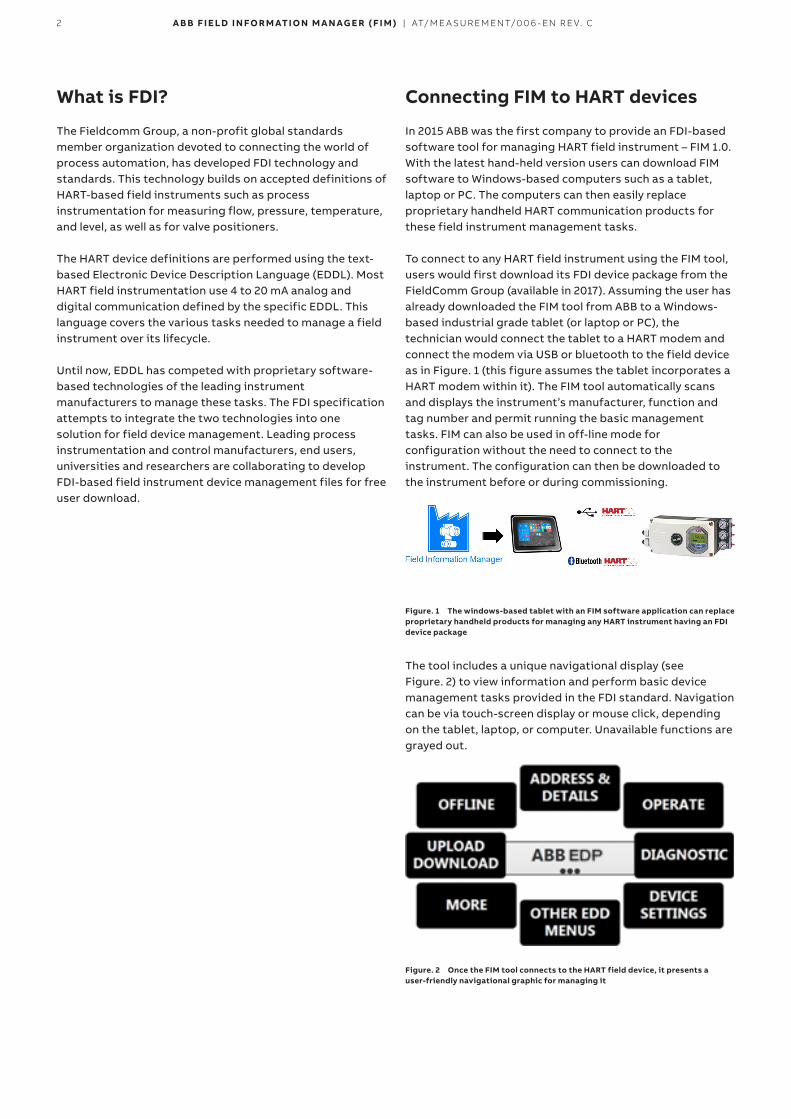
To connect to any HART field instrument using the FIM tool, users would first download its FDI device package from the FieldComm Group (available in 2017). Assuming the user has already downloaded the FIM tool from ABB to a Windows-based industrial grade tablet (or laptop or PC), the technician would connect the tablet to a HART modem and connect the modem via USB or bluetooth to the field device as in Figure. 1 (this figure assumes the tablet incorporates a HART modem within it). The FIM tool automatically scans and displays the instrument’s manufacturer, function and tag number and permit running the basic management tasks. FIM can also be used in off-line mode for configuration without the need to connect to the instrument. The configuration can then be downloaded to the instrument before or during commissioning.
Figure. 1 The windows-based tablet with an FIM software application can replace proprietary handheld products for managing any HART instrument having an FDI device package
The tool includes a unique navigational display (see Figure. 2) to view information and perform basic device management tasks provided in the FDI standard. Navigation can be via touch-screen display or mouse click, depending on the tablet, laptop, or computer. Unavailable functions are grayed out.
Figure. 2 Once the FIM tool connects to the HART field device, it presents a user-friendly navigational graphic for managing it
3A B B F I E LD I N FO R M ATI O N M A N AG E R ( F I M ) | AT/M E A SU R EM ENT/0 0 6 - EN R E V. C
Adding device management capabilities
At this point Device Descriptions (DD) have limitations compared to many existing stand-alone Windows-based drivers for managing HART-based field instruments. While DDs can handle the basic tasks of configuration, commissioning, diagnosis and calibration, they lack some of the useful specialized features and complex graphic capabilities available in proprietary technologies. Currently, unavailable features in the DD include offline configuration, archiving and complex graphics. Also missing is a print function! The software-based technologies, on the other hand, provide the special features and excel in diagnostics and advanced asset management.
Managing some field instruments may not require these special capabilities. But certain field instruments could benefit, such as valve positioners and Coriolis flowmeters. For these cases process instrument manufacturers can develop User Interface Plug-ins (UIPs) that are part of the FDI Device Package. ABB has developed such a plug-in for its EDP300 electro-pneumatic valve positioner (see next section). The company is busy developing UIPs for other ABB field instruments that could benefit from enhanced asset management capabilities. These UIPs are part of the Device Package and provide the advanced capabilities at a mouse click or via a touch-screen tablet.
If the manufacturer has provided a UIP within the FDI Device Package for the field device, technicians will also be able to perform instrument diagnosis that includes performance verification, trends, archiving and complex graphics. Moreover, they will be able to print PDFs of device settings and view the results of the instrument performance.
With the EDP300 UIP for Valve Maintenance, ABB has proven that FDI is capable to be the successor for FDT/DTM and pure DDs.
Extended FIM diagnostics with ABB’s EDP300 positioner valve maintenance UIP
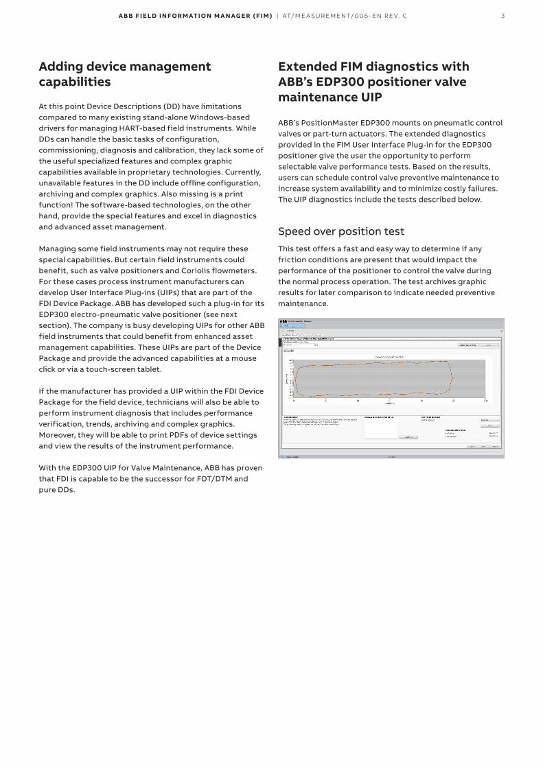
ABB’s PositionMaster EDP300 mounts on pneumatic control valves or part-turn actuators. The extended diagnostics provided in the FIM User Interface Plug-in for the EDP300 positioner give the user the opportunity to perform selectable valve performance tests. Based on the results, users can schedule control valve preventive maintenance to increase system availability and to minimize costly failures. The UIP diagnostics include the tests described below.
Speed over position testThis test offers a fast and easy way to determine if any friction conditions are present that would impact the performance of the positioner to control the valve during the normal process operation. The test archives graphic results for later comparison to indicate needed preventive maintenance.
4 A B B F I E LD I N FO R M ATI O N M A N AG E R ( F I M ) | AT/M E A SU R EM ENT/0 0 6 - EN R E V. C
…Extended FIM diagnostics with ABB’s EDP300 positioner valve maintenance UIP
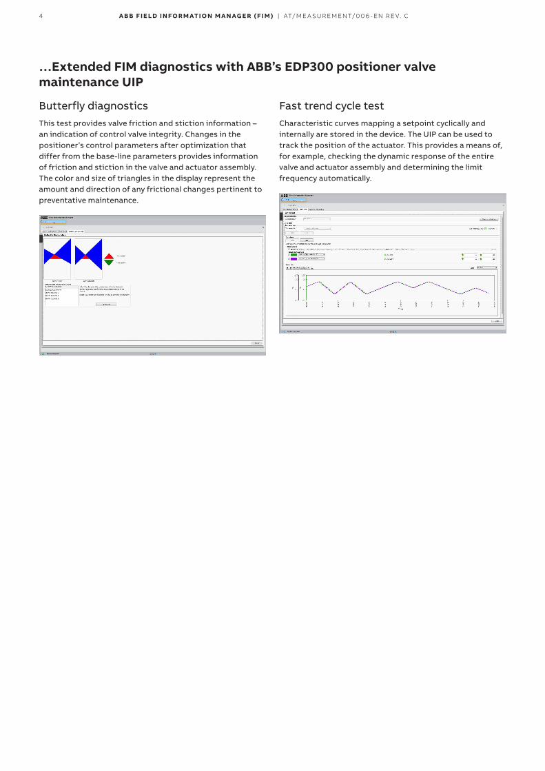
Butterfly diagnosticsThis test provides valve friction and stiction information – an indication of control valve integrity. Changes in the positioner’s control parameters after optimization that differ from the base-line parameters provides information of friction and stiction in the valve and actuator assembly. The color and size of triangles in the display represent the amount and direction of any frictional changes pertinent to preventative maintenance.
Fast trend cycle testCharacteristic curves mapping a setpoint cyclically and internally are stored in the device. The UIP can be used to track the position of the actuator. This provides a means of, for example, checking the dynamic response of the entire valve and actuator assembly and determining the limit frequency automatically.
5A B B F I E LD I N FO R M ATI O N M A N AG E R ( F I M ) | AT/M E A SU R EM ENT/0 0 6 - EN R E V. C
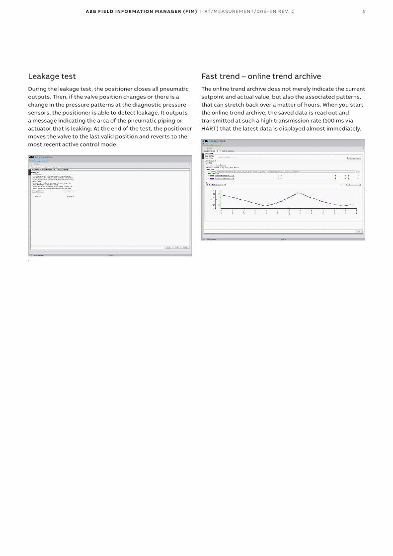
Leakage testDuring the leakage test, the positioner closes all pneumatic outputs. Then, if the valve position changes or there is a change in the pressure patterns at the diagnostic pressure sensors, the positioner is able to detect leakage. It outputs a message indicating the area of the pneumatic piping or actuator that is leaking. At the end of the test, the positioner moves the valve to the last valid position and reverts to the most recent active control mode
.
Fast trend – online trend archiveThe online trend archive does not merely indicate the current setpoint and actual value, but also the associated patterns, that can stretch back over a matter of hours. When you start the online trend archive, the saved data is read out and transmitted at such a high transmission rate (100 ms via HART) that the latest data is displayed almost immediately.
6 A B B F I E LD I N FO R M ATI O N M A N AG E R ( F I M ) | AT/M E A SU R EM ENT/0 0 6 - EN R E V. C
…Extended FIM diagnostics with ABB’s EDP300 positioner valve maintenance UIP
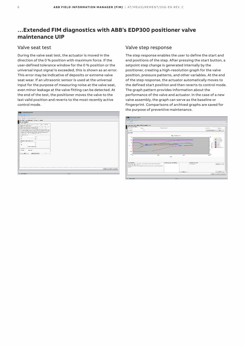
Valve seat testDuring the valve seat test, the actuator is moved in the direction of the 0 % position with maximum force. If the user-defined tolerance window for the 0 % position or the universal input signal is exceeded, this is shown as an error. This error may be indicative of deposits or extreme valve seat wear. If an ultrasonic sensor is used at the universal input for the purpose of measuring noise at the valve seat, even minor leakage at the valve fitting can be detected. At the end of the test, the positioner moves the valve to the last valid position and reverts to the most recently active control mode.
Valve step responseThe step response enables the user to define the start and end positions of the step. After pressing the start button, a setpoint step change is generated internally by the positioner, creating a high-resolution graph for the valve position, pressure patterns, and other variables. At the end of the step response, the actuator automatically moves to the defined start position and then reverts to control mode. The graph pattern provides information about the performance of the valve and actuator. In the case of a new valve assembly, the graph can serve as the baseline or fingerprint. Comparisons of archived graphs are saved for the purpose of preventive maintenance.
7A B B F I E LD I N FO R M ATI O N M A N AG E R ( F I M ) | AT/M E A SU R EM ENT/0 0 6 - EN R E V. C
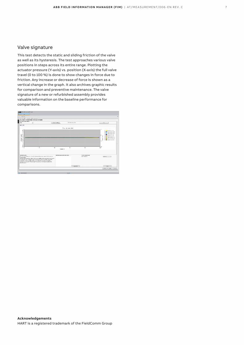
Valve signatureThis test detects the static and sliding friction of the valve as well as its hysteresis. The test approaches various valve positions in steps across its entire range. Plotting the actuator pressure (Y-axis) vs. position (X-axis) the full valve travel (0 to 100 %) is done to show changes in force due to friction. Any increase or decrease of force is shown as a vertical change in the graph. It also archives graphic results for comparison and preventive maintenance. The valve signature of a new or refurbished assembly provides valuable information on the baseline performance for comparisons.
AcknowledgementsHART is a registered trademark of the FieldComm Group
—
ABB Limited Measurement & AnalyticsHoward Road, St. Neots Cambridgeshire, PE19 8EU UK Tel: +44 (0) 870 600 6122 Fax: +44 (0)1480 217948 Email: [email protected]
ABB Inc. Measurement & Analytics125 E. County Line Road Warminster, PA 18974 USA Tel: +1 215 674 6000Fax: +1 215 674 7183
ABB Automation Products GmbH Measurement & AnalyticsSchillerstr. 72 32425 Minden Germany Tel: +49 571 830-0 Fax: +49 571 830-1806
abb.com/measurement
—We reserve the right to make technical changes or modify the contents of this document without prior notice. With regard to purchase orders, the agreed particulars shall prevail. ABB does not accept any responsibility whatsoever for potential errors or possible lack of information in this document.
We reserve all rights in this document and in the subject matter and illustrations contained therein. Any reproduction, disclosure to third parties or utilization of its contents – in whole or in parts – is forbidden without prior written consent of ABB.
©ABB 2018All rights reserved. AT
/ME
AS
UR
EM
EN
T/0
06
-EN
Rev
. C
11.2
018


![Honeywell Field Device Manager Specification · Honeywell Field Device Manager Specification, EP03-480-500 2 [Title] Honeywell Proprietary April 2018 Revision History . Revision Date](https://img.dokumen.tips/doc/110x75/5e8087737b7b492f6f49e44b/honeywell-field-device-manager-specification-honeywell-field-device-manager-specification.jpg)