Embed Size (px)
Citation preview
A Visual Compass based on SLAMJ. M. M. Montiel
Dpt. de Informatica e Ingenieria de SistemasUniversidad de Zaragoza. Spain
Email: [email protected]
Andrew J. DavisonDepartment of Computing
Imperial College London. UKEmail: [email protected]
Abstract— Accurate full 3 axis orientation is computed usinga low cost calibrated camera. We present a simultaneous sensorlocation and mapping method that uses a purely rotating cameraas sensor and distant points, ideally at infinity, as features. Asmooth constant angular velocity pure rotation motion modelcodifies the camera location. Because of the sequential EKFapproach used, and the number of features in the map, abouta hundred, the proposed method has been implemented in realtime at standard video rates.
Experimental results with real images show that the system isable to close loops with 360
pan and 360 cyclotorsion rotations.
Sequences show good performance under challenging conditions:hand-held camera, varying natural outdoor illumination, low costcamera and lens and people moving in the scene.
I. INTRODUCTION
Despite the overwhelming biological evidence for the suit-ability of vision as a primary sensor for simultaneous sensorlocation and map building, it has proven difficult to matchthose capabilities using the state of the art digital hardware.Recently however, the breakthrough work by Davison [1], hasproven the possibility of doing real time visual SLAM withstandard low cost camera hardware.
Our goal is to build full 3 axis visual compass usingstandard low cost computer vision hardware, making the mostof the prior information available, namely a calibrated wideangle camera gathering sequences at 30 fps. while undergoingsmooth motion, and observing a scene where points are atdistances much bigger than the camera translation. We closelyobserve the real time constraint using sequential algorithmsable to run online; in fact, between submission and acceptanceof the paper, we have a C++ version successfully running at30 fps for maps up to 100 features.
Our work has strong links with [1]; it can be considered aspecialization of this work for a rotating camera and featuresat infinity, in fact we use for the camera rotation part exactlythe same motion model. In any case both works are quitecomplementary because [1] cannot cope with the rotatingcamera case nor with features at infinity. It is focused on closeto camera features because it is difficult to represent depthuncertainty for distant ones. We consider this visual compassas the first step for real time outdoor visual SLAM, where weexpect to have both close and distant points.
Some of the advantages of the visual compass system inthis paper are:
• Instant start up from any camera orientation or velocity.No initialisation step or known scene objects are needed.
In fact the tracking can be started from any frame of thesequence.
• Good performance rejecting non rigid motion objects.• Routine loop closing. Our experimental results show that
standard sequential processing can deal with loop closingwithout any special steps. This is a desirable feature fora real-time system.
Davison’s work alloys basic vision point matching tech-niques, gaussian SLAM and particle filtering to detect the un-derlying geometry in a sequence observed by a moving hand-held camera. This geometry considers a selected reduced set oftrackable 3D points (the map), and the camera motion jointlyin the same random vector. This joint modeling allows theobservation of the very same features in all the images and theability to close loops. The loop closing prevents an explosionin the number of features when the sensor moves indefinitelyin a confined area revisiting previously observed areas. Imagesequences repeatedly observing the same environment have aunderlying model that SLAM methods detect and exploit.
The standard approach to SLAM is based on the stochasticmap proposed initially by Smith and Cheesman in [2] whichoffers a powerful tool to model the geometrical location errors.It has been widely used in mobile robotics for processing ge-ometrical information coming for a range of different sensors,odometry, laser range finder, sonar, and vision among others[3]–[6].
In the computer vision literature the family of methodsknown as Structure From Motion, (SFM), focus on the redun-dancy that several observations of the same scene have becauseall the matched features shuould be consistent with a projectivecamera model. These methods can deal with small sets ofshots and with sequences. During the last decade (see [7]for a review) understanding of this underlying geometry andits recover by means of robust statics has produced workingmethods for dealing with wide-baselines and sequences withvariable and unknown camera parameters. SFM primarilyintended for batch processing, has been successfully appliedfor real time robotics in [8]. SFM methods do not modelthe camera an the scene in a unique random vector, so theobserved features along the sequence are not intended to bepersistent, and this makes difficult loop closing. Not dealingwith loops has two main drawbacks: the first is that the sizeof the map for a confined area increases indefinitely, andsecondly the tight constraints that a loop close enforces inthe reconstruction, sequential or batch are also missed.
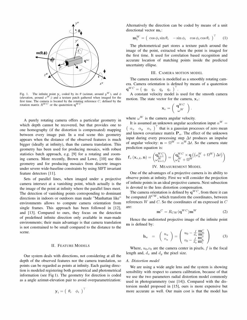
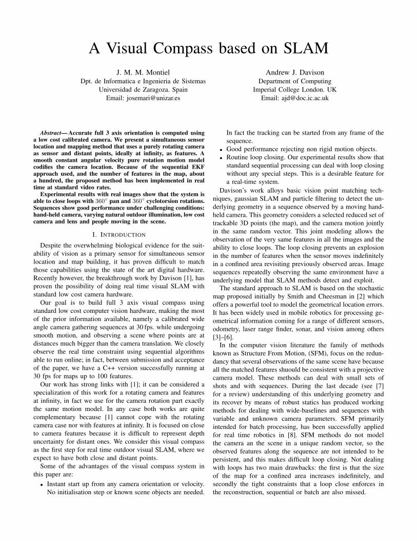
Fig. 1. The infinite point yi coded by its θ (azimut, around yW ), and φ(elevation, around xW ;) and a texture patch gathered when imaged for thefirst time. The camera is located by the rotating reference C, defined by therotation matrix RWC or the quaternion q
WC
A purely rotating camera offers a particular geometry inwhich depth cannot be recovered, but that provides one toone homography (if the distortion is compensated) mappingbetween every image pair. In a real scene this geometryappears when the distance of the observed features is muchbigger (ideally at infinity), than the camera translation. Thisgeometry has been used for producing mosaics, with robuststatistics batch approach, e.g. [9] for a rotating and zoom-ing camera. More recently, Brown and Lowe, [10] use thisgeometry and for producing mosaics from discrete imagesunder severe wide-baseline constraints by using SIFT invariantfeature detectors [11].
Sets of parallel lines, when imaged under a projectivecamera intersect at a vanishing point, which actually is thethe image of the point at infinity where the parallel lines meet.The detection of vanishing points corresponding to dominantdirections in indoors or outdoors man made ”Manhattan like”environments allows to compute camera orientation fromsingle frames. This approach has been followed in [12],and [13]. Compared to ours, they focus on the detectionof predefined infinite direction only available in man-madeenvironments; their main advantage is that camera translationis not constrained to be small compared to the distance to thescene.
II. FEATURE MODELS
Our system deals with directions, not considering at all thedepth of the observed features nor the camera translation, sopoints can be regarded as points at infinity. Each gazing direc-tion is modeled registering both geometrical and photometricalinformation (see Fig 1). The geometry for direction is codedas a angle azimut-elevation pair to avoid overparametrization:
yi =(
θi φi
)>
Alternatively the direction can be coded by means of a unitdirectional vector mi:
mWi =
(
cos φi sin θi − sin φi cos φi cos θi
)> (1)
The photometrical part stores a texture patch around theimage of the point, extracted when the point is imaged forthe first time. It used for correlation based recognition andaccurate location of matching points inside the predicteduncertainty ellipse.
III. CAMERA MOTION MODEL
The camera motion is modelled as a smoothly rotating cam-era. Camera orientation is defined by means of a quaternionqWC =
(
q0 qx qy qz
)>.A constant velocity model is used for the smooth camera
motion. The state vector for the camera, xv:
xv =
(
qWC
ωW
)
.
where ωW is the camera angular velocity.It is assumed an unknown angular acceleration input αW =
(
αx αy αz
)> that is a gaussian processes of zero meanand known covariance matrix Pα. The effect of the unknowninput during every processing step ∆t produces an impulseof angular velocity: n = ΩW = αW ∆t. So the camera stateprediction equation is:
fv (xv,k,n) =
(
qWCk+1
ωWk+1
)
=
(
qWCk × q
((
ωWk + ΩW
)
∆t)
ωWk + ΩW
)
IV. MEASUREMENT MODEL
One of the advantages of a projective camera is its ability toobserve points at infinity. First we will consider the projectionof infinite points in an ideal projective camera. Next subsectionis devoted to the lens distortion compensation.
The camera orientation is defined by qWC , from there it canbe computed RCW , which transform the coordinates, betweenreferences W and C. So the coordinates of m expressed in C
are:mC = RCW (qWC)mW (2)
Hence the undistorted projective image of the infinite pointm is defined by:
hu =
(
uu
vu
)
=
u0 −fdx
mCx
mCz
v0 −fdy
mCy
mCz
(3)
Where, u0,v0 are the camera center in pixels, f is the focallength and, dx and dy the pixel size.
A. Distortion modelWe are using a wide angle lens and the system is showing
sensibility with respect to camera calibration, because of thatwe use the two parameters radial distortion model commonlyused in photogrammetry (see [14]). Compared with the dis-torsion model proposed in [15], ours is more expensive butmore accurate as well. Our main cost is that the model has
not closed form for the distorsion of coordinates nor for itsjacobian.
To recover the ideal projective undistorted coordinates hu =(uu, vu)
>, from the actually distorted ones gathered by thecamera, hd = (ud, vd)
>, the next formulas are applied:
hu
(
ud
vd
)
=
(
u0 + (ud − u0)(
1 + κ1r2d + κ2r
4d
)
v0 + (vd − v0)(
1 + κ1r2d + κ2r
4d
)
)
rd =
√
(dx (ud − u0))2
+ (dy (vd − v0))2 (4)
To compute the distorted coordinates from the undistorted:
hd
(
uu
vu
)
=
u0 + (uu−u0)
(1+κ1r2
d+κ2r4
d)
v0 + (vu−v0)
(1+κ1r2
d+κ2r4
d)
(5)
ru = rd
(
1 + κ1r2d + κ2r
4d
)
(6)
ru =
√
(dx (uu − u0))2
+ (dy (vu − v0))2 (7)
Being the problem that formula (5) depends on rd that hasto be solved from (6), e.g using Newton-Raphson, once ru iscomputed from (7).
In summary:
h(
yi,qWC
)
= hd
(
hu
(
mC(yi, RCW (qWC))))
(8)
given an infinite point yi and a camera position qWC itis computed its image. It the composition of expressions(1,2,3,5).
Equation (8), can be inverted giving an analytic expressionfor yi
yi = y(
zi,qWC
)
(9)
from a single infinite point observation zi and the cameraorientation qWC .
Despite the accurate calibration, because of the radial dis-tortion, points close to the center are more accurate than pointsclose to the image border. Because of that we have applied aheuristic covariance assignment for image points that increasesthe standard deviation linearly with the radius with respect tothe image center:
σh = σh0
(
1 + βrd
rdmax
)
rdmax=
√
u20 + v2
0 (10)
rd is computed using (4). In our experiments, σh0= 2pixel
and β = 1. And for every point, the corresponding measure-ment noise matrix:
Ri =
(
σ2h 00 σ2
h
)
Undistortion jacobian, ∂hu
∂hd
has analytical expression:
(
1 + κ1r2d + κ2r
4d
)
+
2 ((ud − u0) dx)2×
(
κi + 2κ2r2d
)
2d2y (ud − u0) (vd − v0)×
(
κ1 + 2κ2r2d
)
2d2x (vd − v0) (ud − u0)×
(
κ1 + 2κ2r2d
)
(
1 + κ1r2d + κ2r
4d
)
+
2 ((vd − v0) dy)2×
(
κi + 2κ2r2d
)
(11)
Fig. 2. New features initialization and patch prediction. Right image showsacceptance region and the matched measurement. The acceptance region hasbeen magnified for displaying
The jacobian for the distortion is computed by invertingexpression (11).
V. KALMAN FILTER SEQUENTIAL PROCESSING
The classical prediction-match-update EKF is applied [16]to deal with geometrical information producing an ellipticalacceptance region where the measurement should be. Theusage of the photometrical data plays key role to determinewhere inside the region the actual matching measurement.
All the estimated variables: the camera state xv and all theestimated features yi i = 1 . . . n are considered in a jointgaussian state: x =
(
xv y1 . . . yn
)> vector with itscorresponding covariance P.
Next the EKF steps are detailed:a) Prediction:
xk+1|k =
fv
(
xv,k|k, 0)
y1,k|k
. . .
Pk+1|k = FPk+1|kF> + G
(
(∆t)2Pα 0
0 0
)
G>
F = diag(
∂fv
∂xv
, I
)
G = diag(
∂fv
∂n, 0
)
And hence the predicted features in the image:
hi,k+1|k = h(
yi,k+1|k, xv,k+1|k
)
each predicted feature, has associated a two linearized mea-surement equations, defined by the two rows matrix, composedof a 02×2 block except for the considered feature:
Hi =
(
∂h
∂xv
, 012×2, . . . , 0
i−12×2,
∂h
∂yi
, 0i+12×2, . . . , 0
n2×2
)
All the Hi are piled up vertically to produce the fulllinearized measurement equation H, and hence the innovationcovariance is derived:
Sk+1|k = HPk+1|kH> + diag (R1, . . . ,Rn)
b) Match: Every prediction hi,k+1,k and its correspond-ing Si,k+1|k 2 × 2 diagonal submatrix matrix extracted fromSk+1|k define an elliptical acceptance region in the imagewhere the image of the predicted feature should be:
(u, v)S−1i,k+1|k
(
u
v
)
≤ χ20.05,2
For every map feature, when it was imaged for the first time,we have stored both a texture patch and the camera orientation,then at the prediction stage, the image of the predicted patchis synthesized being quite effective for dealing with distortion,and cyclotorsion. Figure2 shows an example of the stored andpredicted patches.
A normalized correlation score is computed for every pixelin that region, the highest score, over a threshold, is con-sidered to be matching measurement zi,k. See figures fig-prediction 3 and 5 for examples of this regions. It has to benoted that we only use a feature detector at the initializationstage (see Sec. VII), at the matching stage no feature detectionis performed in the acceptance region and the predicted patchcorrelation score is computed with respect to all the pixels inthe region.
c) Update: Using only the submatrices correspondingwith actually matched features, Hm,Rm, hm and zm are builtand hence the state estimate is updated:
xk+1|k+1 = xk+1|k + K(
zm − hm
)
K = Pk+1|kH>m
(
HmPk+1|kH>m + Rm
)−1
Pk+1|k+1 = (I − KHm) Pk+1|k
Finally the camera orientation quaternion is normalized. ThePk+1|k+1, has to be affected by the corresponding normaliza-tion jacobian.
VI. STATE INITIALIZATION
As an infinite point can be initialized from a single image(see eq. 9), the camera initial state is null rotation and nullangular velocity:
xv,0|0 =(
1 0 0 0 0 0 0)> (12)
P0|0 = diag(
0 0 0 0 σ2Ω σ2
Ω σ2Ω
)
(13)
The camera orientation for the first frame is considered asthe reference frame, hence the null uncertainty in orientation.For the angular velocity, a high value is assigned to σΩ, inour case
√
(2) radsec , in order to deal with an initial unknown
velocity. This is a remarkable system characeristic that allowsto initialize the map from any frame, at any initial angularvelocity. In fact in the experiments, the initial angular velocityis not null.
Once the initial value for the camera vector has beendefined, about 10 well spread over the image Harris [17] pointsare detected and the corresponding scene features initialized,expanding the state vector as defined in the next section.
VII. FEATURE INITIALIZATION AND DELETION
Once a new image is processed, if the number of featurespredicted to be visible inside the image goes below a threshold,in our case 14, a new feature is initialized. An area withoutfeatures is searched randomly in the image, if found the mostsalient interest point in that area, zj , is located using Harrispoint detector. Figure 2 shows an initialization example.
For every new measurement the corresponding feature es-timate is computed using equation (9) and the state vector isexpanded with the new feature estimate yj . The covariancematrix has to be expanded as well:
Pnewk|k = J
(
Pk|k 00 Rj
)
J>, J=
(
I 0J1
)
, J1 =
(
∂h−1
∂xv
, 0, . . . ,∂h
−1
∂zi
)
Features that are predicted to be in the image but notmatched are deleted based on the accumulated ratio betweentimes visible and times effectively matched. This simple mech-anism allows us to delete non trackable features for examplethose over non rigid objects (see fig 4 (a)). The deletion methodallows us to remove non persistent static scene elements if ascene is continuously revisisited.
VIII. EXPERIMENTAL RESULTS
The experiments, currently programmed in Matlab, aredirected to test the feasibility of the system for real timeperformance. In particular we are focusing the 360 loopclosing because this will allow us to completely map a scene.In fact, between submission and acceptance of the paper, wehave a C++ version successfully running at 30 fps for mapsup to 100 features
Two sequences of an outdoor scene have been acquired witha rotating camera. The processed images were 90 field ofview, 320 × 240 B&W, acquired at 30 fps. with a low costUnibrain IEEE1394 camera.
The sequences are challenging because only the cameratranslation were tightly controlled; there were pedestrianswalking around and cars moving along a road; the cameraautomatic control exposition introduces a great deal of changein the image contrast and brightness in response to theoutdoors natural illumination conditions.
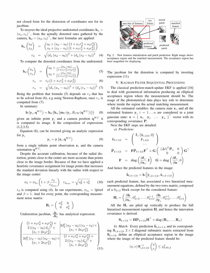
The fist sequence is on a tripod 360 pan sequence. Beingthe camera on at tripod the translation is almost assured tobe about 1-2cm. and the camera motion is approximatelyrepetitive. Figure 3 shows frames with the acceptance regionfor every predicted feature and the matched observation. Theselected frames are the beginning (frame 14) and the loopclosing (frame 286). It is seen how among the first 3 revisitedfeatures, 2 were not matched and the third was detected veryclose to the limit; however in next frame and all the following(frame 319) the reobserved features are regarded as such. Itshould be noticed that the loop is closed with the normalsequential prediction-match-update, without being necessaryany additional computation.
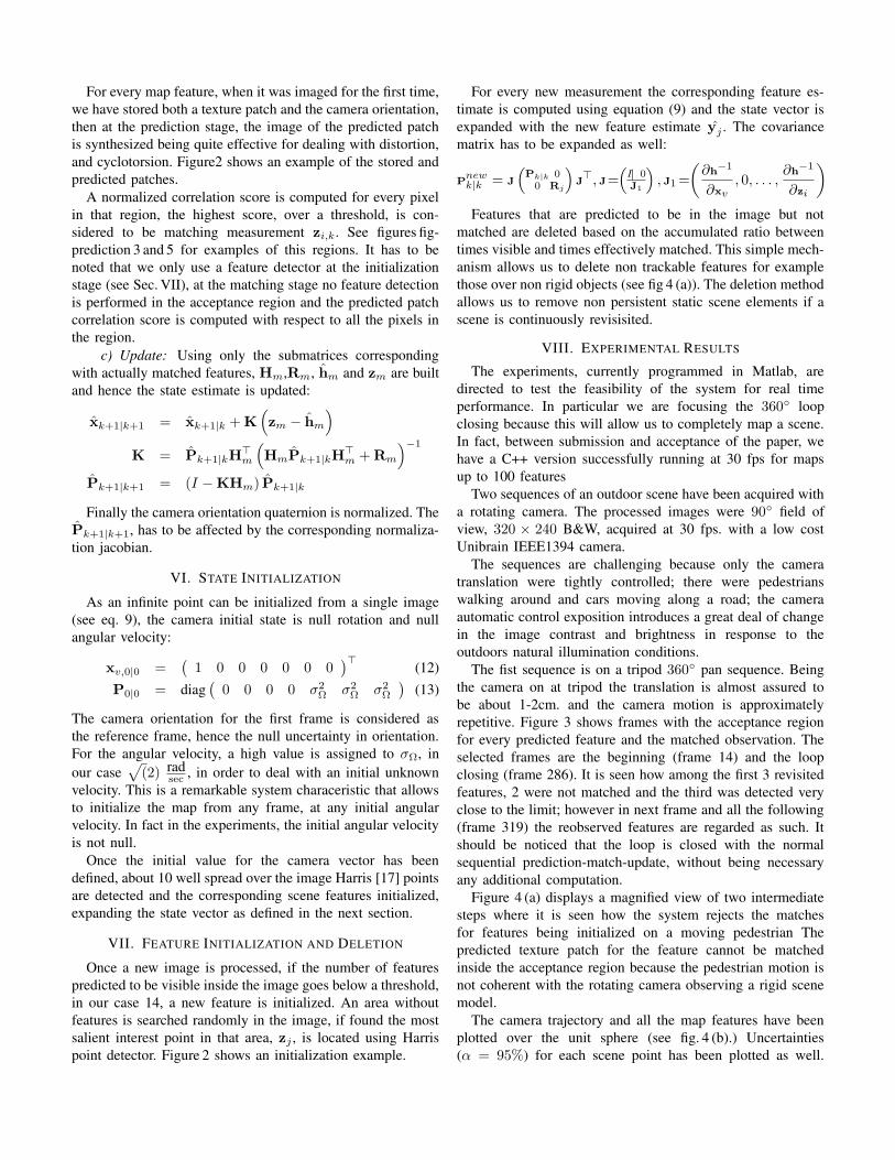
Figure 4 (a) displays a magnified view of two intermediatesteps where it is seen how the system rejects the matchesfor features being initialized on a moving pedestrian Thepredicted texture patch for the feature cannot be matchedinside the acceptance region because the pedestrian motion isnot coherent with the rotating camera observing a rigid scenemodel.
The camera trajectory and all the map features have beenplotted over the unit sphere (see fig. 4 (b).) Uncertainties(α = 95%) for each scene point has been plotted as well.

Fig. 3. Loop closing. From left to right frames 14, 286 and 319. It is shown how two features are lost, and a feature has been matched close to the limit ofthe acceptance region. The rest of the map features has been correctly matched, can be verified comparing frames 14 and 319.
The sphere surface has been magnified around the estimatedcamera trajectory to illustrate the rotation accuracy; the camerawas on a tripod so the first and the second lap should be close.
The second sequence (see Fig. 5) is more challenging be-cause the camera is hand-held, and the trajectory includes botha 360 pan and 360 cyclortorsion; the outdoor natural illumi-nation was challenging as well. The systems also performedsuccessfully. From top left to right bottom, several sequenceframes, with the predicted acceptance regions are shown. Thirdimage in the second shows that loop is closed without loosingany of the reobserved features. The camera trajectory over theunit sphere is displayed as well.
IX. CONCLUSION
A SLAM visual compass has been build and tested off lineon outdoor sequences gathered with a hand-held and on atripod camera. The sequences were challenging because of thenatural illumination and the moving pedestrians. The ability toclose loops reidentifying most of the persistent map featuresinside of the acceptance 95% region is a clear signal of thecorrectness of the gaussian stochastic model for coding thegeometry of the scene.
Because of the number of features, about a hundred, andthe sequential processing this system can, and has been,implemented in real time hence being effectively a real timevisual compass.
Our proposal has strong links with the existent real timesystem proposed in [1] that only deals with features close tothe camera. Besides our proposal shows that distant points canprovide a robust and accurate information about orientation,specially outdoors. This extend the applicability of SLAMreal time computer vision combining both points close to thecamera and points at infinity.
Beside the direct application in mobile robotics, this workshows the feasibility of SLAM to process image sequencesand its ability to detect a map composed of a reduced set oftrackable features, selected for being detectable in the frameswhere they should visible; this turns out to be a reducedset of key features detected also at loop closing. This loopclosing matches provide a rich information not only for realtime processing but also to for batch non-linear optimizationmethods. In particular this system could be well used for buildimage mosaics for sequences both real time or off line.
ACKNOWLEDGMENTProject founded by the Spanish CICYT DPI2003-07986, Spanish
Ministerio de Educacion y Ciencia PR2005-0332, EPSRC grantGR/T24685 and an EPSRC Advanced Research Fellowship to AJD.
We are very grateful to David Murray and other members ofOxford’s Active Vision Laboratory for discussions and softwarecollaboration.
REFERENCES
[1] A. Davison, “Real-time simultaneous localization and mapping with asingle camera,” in ICCV, 2003.
[2] R. C. Smith and P. Cheeseman, “On the representation and estimation ofspatial uncertainty,” Int. J. Robotics Research, vol. 5, no. 4, pp. 56–68,1986.
[3] J. Castellanos and J. Tardos, Mobile Robot Localization and MapBuilding: A Multisensor Fusion Approach. Boston. USA: KluwerAcademic Publishers, 1999.
[4] J. Castellanos, J. Montiel, J. Neira, and J. Tardos, “Sensor influencein the performance of simultaneous mobile robot localization and mapbuilding,” in Experimental Robotics VI. Lecture Notes in Control andInformation Sciences. Vol 250, P. Corke and J. Trevelyan, Eds. Springer-Verlag, 1994, pp. 287 – 296.
[5] H. Feder, J. Leonard, and C. Smith, “Adaptive mobile robot navigationand mapping,” Int. Journal of Robotics Research, vol. 18, no. 7, pp.650–668, 1999.
[6] D. Ortın, J. M. M. Montiel, and A. Zisserman, “Automated multisensorpolyhedral model acquisition,” in ICRA, 2003.
[7] R. I. Hartley and A. Zisserman, Multiple View Geometry in ComputerVision, 2nd ed. Cambridge University Press, ISBN: 0521540518, 2004.
[8] D. Nister, O. Naroditsky, and J. Bergen, “Visual odometry,” in Proc.IEEE Computer Society Conference on Computer Vision and PatternRecognition, 2004, pp. 652–659.
[9] L. de Agapito, E. Hayman, and I. A. Reid, “Self-calibration of rotatingand zooming cameras,” Int. J. of Computer Vision, vol. 45, no. 2, pp.107–127, Nov 2001.
[10] D. Brown, M.and Lowe, “Recognising panoramas,” in InternationalConference on Computer Vision, Nice, 2003, pp. 1218–1225.
[11] D. Lowe, “Distinctive image features from scale-invariant keypoints,”Int. J. of Computer Vision, vol. 60, no. 2, pp. 91–110, 2004.
[12] J. Kosecka and W. Zhang, “Video compass,” in European Conferenceon Computer Vision, June 2002, pp. 476–491.
[13] J. M. M. Montiel and A. Zisserman, “Automated architectural acquisitionfrom a camera undergoing planar motion,” in International Symposiumon Virtual and Augmented Architecture, 2001.
[14] E. Mikhail, J. Bethel, and M. J.C., Introduction to Modern Photogram-metry. John Wiley & Sons, 2001.
[15] A. Davison, Y. G. Cid, and N. Kita, “Real-time 3D SLAM with wide-angle vision,” in Proc. IFAC Symposium on Intelligent AutonomousVehicles, Lisbon, Jul 2004.
[16] Y. Bar-Shalom and T. E. Fortmann, Tracking and Data Association, ser.Mathematics in Science and Engineering. San Diego: Academic Press,INC., 1988, vol. 179.
[17] C. Harris and M. Stephens, “A combined corner and edge detector,” inProceedings of the 4th Alvey Vision Conference, 1988, pp. 147–151.
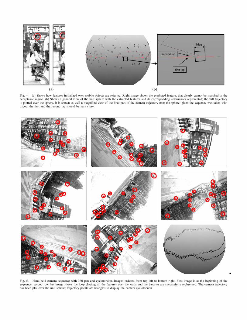
(a) (b)Fig. 4. (a) Shows how features initialized over mobile objects are rejected. Right image shows the predicted feature, that clearly cannot be matched in theacceptance region. (b) Shows a general view of the unit sphere with the extracted features and its corresponding covariances represented; the full trajectoryis plotted over the sphere. It is shown as well a magnified view of the final part of the camera trajectory over the sphere; given the sequence was taken withtripod, the first and the second lap should be very close.
Fig. 5. Hand-held camera sequence with 360 pan and cyclotorsion. Images ordered from top left to bottom right. First image is at the beginning of thesequence, second row last image shows the loop closing; all the features over the walls and the banister are successfully reobserved. The camera trajectoryhas been plot over the unit sphere; trajectory points are triangles to display the camera cyclotorsion.