Embed Size (px)
Citation preview
61AUtility’sExperienceintheImplementationofSubstationAutomationProjects
1.IntroductioneThekwini Electricity has embarked on substation automation projects since the early introduction of substation specific communications standards and is presently in the process of implementing substation automation projects based on the IEC61850 standard at eight new substations.
This paper describes actual substation projects to illustrate the evolution of the introduction of substation automation in terms of objectives, applicable standards and specification methodology. Positive and negative outcomes of the various evolutionary phases are highlighted.
The positive and negative outcomes of the use of substation automation solutions for the various projects are discussed and compared with the initial objectives. The paper concludes with the envisaged adoption of the full IEC61850 model for substation automation.
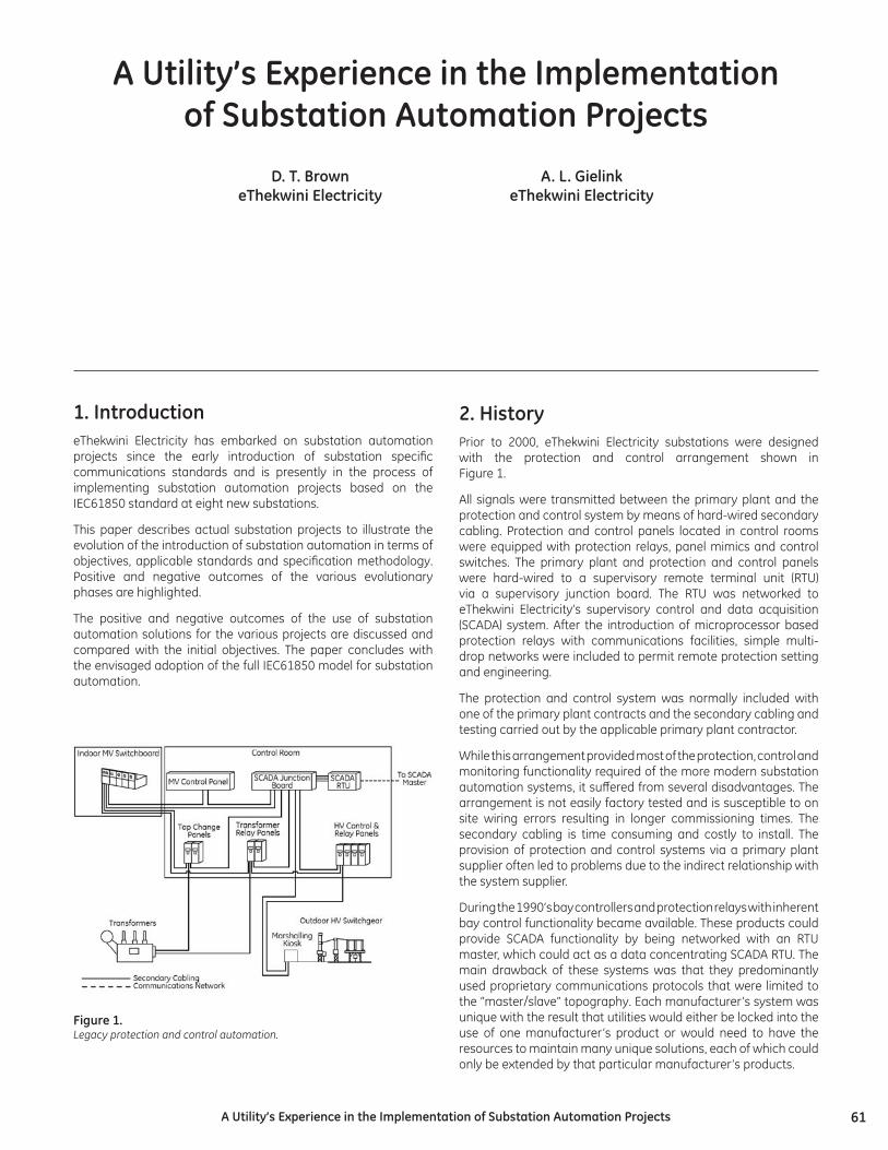
2.HistoryPrior to 2000, eThekwini Electricity substations were designed with the protection and control arrangement shown in Figure 1.
All signals were transmitted between the primary plant and the protection and control system by means of hard-wired secondary cabling. Protection and control panels located in control rooms were equipped with protection relays, panel mimics and control switches. The primary plant and protection and control panels were hard-wired to a supervisory remote terminal unit (RTU) via a supervisory junction board. The RTU was networked to eThekwini Electricity’s supervisory control and data acquisition (SCADA) system. After the introduction of microprocessor based protection relays with communications facilities, simple multi-drop networks were included to permit remote protection setting and engineering.
The protection and control system was normally included with one of the primary plant contracts and the secondary cabling and testing carried out by the applicable primary plant contractor.
While this arrangement provided most of the protection, control and monitoring functionality required of the more modern substation automation systems, it suffered from several disadvantages. The arrangement is not easily factory tested and is susceptible to on site wiring errors resulting in longer commissioning times. The secondary cabling is time consuming and costly to install. The provision of protection and control systems via a primary plant supplier often led to problems due to the indirect relationship with the system supplier.
During the 1990’s bay controllers and protection relays with inherent bay control functionality became available. These products could provide SCADA functionality by being networked with an RTU master, which could act as a data concentrating SCADA RTU. The main drawback of these systems was that they predominantly used proprietary communications protocols that were limited to the “master/slave” topography. Each manufacturer’s system was unique with the result that utilities would either be locked into the use of one manufacturer’s product or would need to have the resources to maintain many unique solutions, each of which could only be extended by that particular manufacturer’s products.
AUtility’sExperienceintheImplementationofSubstationAutomationProjects
D.T.BrowneThekwiniElectricity
A.L.GielinkeThekwiniElectricity
Figure1.Legacy protection and control automation.
62 AUtility’sExperienceintheImplementationofSubstationAutomationProjects
While eThekwini Electricity recognized the potential benefits offered by the use of communication networks to replace hard-wired secondary cabling, the problems associated with the use of proprietary protocols resulted in the decision to maintain the status quo. During the late 1990’s products that made use of a “standard” communication protocol (UCA2.0) over a standard physical layer (Ethernet) became available. Work on the IEC61850 standard had commenced but was far from complete. Based on the assumption that much of the UCA2.0 protocol would find its way into the IEC61850 protocol and that the IP transport layer and Ethernet physical layer would definitely be used for IEC61850, two pilot projects using communication networks between protection relays for substation automation were embarked upon.
3.PilotProject1:
3.1Quarry132kVSwitchyardIn 2000, a tender was advertised for a 132 kV switchyard consisting of eight 132kV feeder bays. The protection and control aspect of the specification was based on a non-networked, hardwired (“legacy”) system and “legacy” wiring schematics were used to indicate the requirements. Tenderers were requested to offer a UCA2.0 based solution and to rationalise the “legacy” arrangement accordingly.
The solution provided made use of a combination of the UCA2.0 and DNP3.0 protocols. UCA2.0 was used to implement peer-to-peer messaging (UCA GOOSE or GSSE) for interlocking and tripping purposes. The Ethernet physical layer for UCA2.0 was also used for protection setting and engineering. A DNP3.0 master/slave network over RS485 was used for SCADA purposes. The solution did not make use of a human machine interface (HMI) computer. A traditional mimic and control switches were provided as part of the protection panels.
While the solution provided the required functions perfectly, several important lessons were learned from this pilot project:
• The use of “legacy” protection and control specifications and drawings resulted in requirements being misinterpreted and philosophy decisions needing to be made by the system integrator.
• The SCADA RTU selected for this project was provided by the existing SCADA Master Station supplier and did not have a means of communicating with the protection relays using TCP/IP over Ethernet. Although the relays were capable of communicating using UCA2.0 or DNP3.0 over Ethernet, the final solution used DNP3.0 over RS485. There were products from other manufacturers available that could have used DNP3.0 over Ethernet and so minimized wiring.
• GOOSE messaging was used for trip and breaker-fail signals between the Busbar Protection scheme and feeder bays. This required a dual redundant Ethernet network for reliability purposes with associated additional costs. The use of GOOSE messaging resulted in there being no simple means of isolating Busbar Protection and associated Breaker Fail tripping which is normally required when testing on a live system. The reliability and speed of GOOSE messaging was, however, proven. The objective of minimizing on-site secondary cabling was achieved in this project.
4.PilotProject2:
4.1Plangweni132/11KVSubstationIn 2002, tenders were advertised for a 132/11kV substation consisting of two 132kV bays, two 132/11kV 30MVA transformers and an eighteen panel indoor 11kV switchboard. A Protection tender was advertised separately from the primary plant tenders for the first time in order that a “first-hand” relationship could be established with the Protection supplier and to ensure that the overall responsibility for the substation automation system remained with a single party. Protection relays were free issued to the 11kV switchgear supplier for installation in the 11kV switchboard.
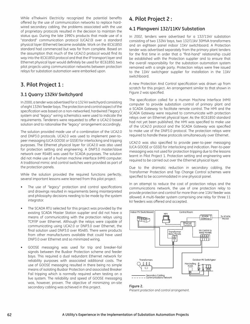
A new Protection And Control specification was drawn up from scratch for this project. An arrangement similar to that shown in Figure 2 was specified.
The specification called for a Human Machine Interface (HMI) computer to provide substation control of primary plant and a SCADA Gateway to facilitate remote control. The HMI and the SCADA Gateway were required to communicate with protection relays over an Ethernet physical layer. As the IEC61850 standard had not yet been published, the HMI was specified to make use of the UCA2.0 protocol and the SCADA Gateway was specified to make use of the DNP3.0 protocol. The protection relays were required to handle these protocols simultaneously over Ethernet.
UCA2.0 was also specified to provide peer-to-peer messaging (UCA GOOSE or GSSE) for interlocking and indication. Peer-to-peer messaging was not used for protection tripping due to the lessons learnt in Pilot Project 1. Protection setting and engineering were required to be carried out over the Ethernet physical layer.
Due to the dramatic reduction in secondary cabling, the Transformer Protection and Tap Change Control schemes were specified to be accommodated in one physical panel.
In an attempt to reduce the cost of protection relays and the communications network, the use of one protection relay to provide protection and control for more than one 11kV feeder was allowed. A multi-feeder system comprising one relay for three 11 kV feeders was offered and accepted.
Figure2.Present protection and control arrangement.
63AUtility’sExperienceintheImplementationofSubstationAutomationProjects
The supplier provided a system compliant with the specification and, for the first time, all communication within a substation (other than time synchronisation) was provided by one physical network. The main objective of minimizing hardwired secondary cabling had been achieved. The number of panels to be accommodated in the control room was vastly reduced allowing the physical size of the control room to be reduced.
The lessons learned from this pilot project were:
• The HMI hardware failed shortly after commissioning apparently due to over-heating. This was despite the specification calling for an “industrial grade” PC. The hardware was replaced but concerns remain over its expected lifespan in comparison with the remainder of the equipment supplied.
• A conventional office/home operating system or a UNIX based operating system were specified as options for the HMI. The conventional home/office operating system was offered and accepted. This operating system has proved unreliable.
• The HMI software used an unproven third-party UCA2.0 driver arrangement which has been unreliable. On many occasions when the system has been left unattended for a number of weeks it has been found in a “crashed” state by operators.
• The arrangement of one protection relay providing protection and control for more than one 11kV feeder was found to be limiting in terms of the allocation of electricity customers and distributor substations to feeder circuits. Customers and distributor substations were required to be fed on circuits which did not share a protection relay to avoid protracted loss of supply for a common source of failure.
5. Development of a specification for substationautomationprojectbasedonIEC61850During 2005, a specification was developed for Protection And Control equipment for eight new substations. The specification for Pilot Project 2 was used as a basis, but was modified to conform to the IEC61850 standard and to eliminate problems identified in the pilot projects. The main features and philosophies are detailed below:
6.SchemeDrawingsTraditionally, tender drawings showed proposed wiring schematics with discrete functional devices to convey protection and control philosophy. These drawings were used by suppliers to develop protection and control schemes using their products.
With the introduction of microprocessor based relays, much of the protection scheme functionality was programmed into the relays instead of being implemented with discrete wired components. With modern substation automation systems virtually all of the scheme functionality is programmed into the relays and only inputs and output contacts are physically wired. Scheme drawings were thus split into wiring schematics and logic schematics.
Wiring schematics were used to indicate all hard-wired connections between the protection and control schemes and the primary plant. These included analogue inputs such as CT’s and VT’s, digital inputs such as switchgear auxiliary switches and alarm contacts and contact outputs for closing and tripping switchgear. These wiring schematics were also used for the primary plant specifications.
Logic schematics showed how inputs and protection functions were to be marshalled through logic gates, latches and timers to operate virtual and contact outputs. These schematics also indicated which logical nodes need to be linked to the HMI and the SCADA Gateway and which were to be available for peer-to-peer links (GOOSE messages).
Issuing logic schematics with the specification proved to be invaluable when addressing queries and approving protection designs.
7.CommunicationsArrangementThe specification called for an arrangement similar to that for Pilot Project 2, shown in Figure 2. The HMI computer and SCADA Gateway were to communicate with protection relays by means of the IEC61850 protocol over the Ethernet physical layer. Peer-to-peer (GOOSE) messaging was to be carried out according to IEC61850. Protection setting and engineering were required to be carried out over the Ethernet physical layer and could make use of an alternative standard protocol.
All Ethernet links to protection relays were to be by means of optic-fibre (100baseF). The Ethernet switches were required to be suitable for use in a substation environment. They were to have no moving parts such as fans and be powered from the substation battery.
Time synchronisation was to be achieved using a separate IRIG-B time synchronisation network. Other options are available that achieve this using the Ethernet network.
8.TheSCADARTUThe existing eThekwini Electricity SCADA Master Station uses the DNP3.0 protocol for communication with substation SCADA RTU’s. The SCADA Gateway was therefore required to provide a DNP3.0 database that could be polled by the Master Station. In previous specifications the SCADA Gateway communicated with protection relays on a substation DNP3.0 network.
This network was over an RS485 physical layer for Pilot Project 1 and over Ethernet for Pilot Project 2.
With the introduction of IEC61850, several manufacturers produced devices capable of populating a DNP3.0 database by communicating with protection relays using the IEC61850 protocol. This functionality was specified for the SCADA Gateway.
64 AUtility’sExperienceintheImplementationofSubstationAutomationProjects
9.TheHumanMachineInterface(HMI)The HMI was required to provide a graphical user interface to allow an operator to view status and carry out control of the primary plant. The HMI was also required to maintain an event record database which could be viewed using the graphical user interface. Operator interaction was required to be via a touch screen. A locked keyboard was to be provided for maintenance of the HMI by select personnel only.
The HMI was required to have a default screen showing an overall substation mimic depicting the status of all primary plant, selected measured values and indication of the presence of alarm conditions and their location(s). The default screen was also required to display an overall event record window showing all substation events and their time stamps in chronological order.
From the overall screen, it was to be possible to “drill-down” into any bay to show the detailed mimic for the bay with measured values and status of alarms. Operation of primary plant was to be carried out from this bay-level screen. The bay-level screen was also required to display a bay-specific event record window showing all events related to the particular bay and their time stamps in chronological order.
Pilot project 2 provided valuable experience regarding the reliability of hardware, operating system and software for the HMI. During the preparation of the latest specification, static electronic HMI products having no moving parts such as fans and hard drives became available. These HMI’s make use of more robust embedded operating systems scaled down to the minimum overhead for the application and are designed specifically for substations in that they make use of the IEC61850 protocol, are designed for DC supplies and conform to the same IEC specifications as normal protection relays. An HMI with the above characteristics was requested as an option in the tender and was offered and accepted. In future specifications static electronic systems will be specified.
Suppliers have often marketed the many additional features that HMI systems can provide such as data-logging and trending, condition monitoring, interlocking and operation sequencing. eThekwini Electricity’s philosophy is that the primary function of the HMI is to provide a point of control and monitoring of the substation plant and that the HMI system should not be burdened with secondary “nice-to-have” functionality that could result in reduced reliability of the primary function. “Mission critical” functionality such as tripping should not be routed via the HMI and important functionality such as interlocking and operation sequencing can be carried out at relay level which is deemed to be more secure.
Many HMI systems offer complex options for operators. eThekwini Electricity’s philosophy is that operators are not required to have a high level of computer literacy and should thus be able to interact with the HMI via a touch screen using simple buttons to navigate and operate the system. The logging in of users was even excluded to improve ease of use. This “shallow learning curve” approach is believed to more likely to gain the acceptance and “buy-in” of operators.
Some HMI systems are able to provide both HMI and SCADA RTU functionality in one device. eThekwini Electricity’s philosophy is that both points of remote control (HMI and SCADA) for the entire substation should not be disabled for a single device failure. Separate devices were thus specified for the HMI and SCADA Gateway. The same device was offered for both applications, the only difference being the provision of a touch screen and keyboard with the HMI device. The benefit arising from this is that the HMI and SCADA Gateway have a common configuration, have common spares and can perform each other’s functions allowing both functions to be available after a single device failure.
It is envisioned that vastly improved reliability will be achieved with the HMI offered over that supplied for Pilot Project 2.
10.TheIEC61850SubstationConfiguration Language (SCL)IEC61850-6 defines a substation configuration language allowing all IEC61850 communication within a substation to be configured with a substation configuration tool.
The substation configuration tool, which could be provided by any party, comprises software that imports the capability data of protection relays in a standard format, carries out substation communication configuration and produces configuration files that are sent to the relays or other devices to fully configure them for the required communications arrangement.
This substation configuration tool effectively configures all relays to serve the appropriate information from their available logical nodes to the HMI and SCADA Gateway clients. It configures the HMI and SCADA Gateway to subscribe to this information and it configures all relays for the required peer-to-peer (GOOSE or GSSE) requirements.
It needs to be stressed that the substation configuration tool is only required to configure the communications arrangement and in no way affects logic configuration or settings within a device. Configuration and settings are performed by the device manufacturer’s configuration software using proprietary methods.
For most IEC61850 compliant HMI and SCADA Gateway systems available, the substation configuration tool forms part of the HMI or Gateway configuration software. All relays that are IEC61850 compliant are supplied with an IED Capability Description (ICD) file. All the ICD files for the relays in the substation can be imported into the substation configuration tool. When the substation configuration is complete a Substation Configuration Description (SCD) file is produced by the substation configuration tool. For most relay manufacturers, this file is then imported by the relay configuration software, which applies the necessary configuration to the relays. This file is also used within HMI or SCADA Gateway configuration software to configure these devices.
Configuration using an IEC61850-6 compliant substation configuration tool was specified, offered and accepted.
65AUtility’sExperienceintheImplementationofSubstationAutomationProjects
11.Peer-To-PeerMessagingUsingIEC61850GOOSEAndGSSEThe specification required peer-to-peer GOOSE or GSSE messaging to be used where information is required to be transmitted from one relay to another. Examples of applications of peer-to-peer messaging are interlocking schemes, automatic switching sequence schemes and indication.
The speed and reliability of GOOSE messaging was proven in Pilot Projects 1 and 2. A frequently overlooked feature of GOOSE is the fact that it is continuously supervised. In between changes of state initiating the sending of a message, the message is continuously sent at configurable intervals indicating no change of state. A subscribing relay that does not receive the message within the configurable interval can assume a loss of communication and initiate an appropriate alarm. The subscriber can also be configured to assume a default state if the message is not received.
GOOSE messages were not to be used for any tripping signals. In feeder and transformer protection schemes GOOSE messaging is of little use for tripping purposes as each protection relay issues a hard-wired trip to the associated circuit breaker/s. For bus bar protection and breaker fail protection schemes there was scope for using GOOSE messaging. eThekwini Electricity has adopted a philosophy not to use this option due to the inability to easily isolate tripping for testing purposes as learnt in Pilot Project 1. A bus-zone and breaker-fail scheme using hard-wired bus wires for tripping signals was specified.
12.IntegrationOfNon-IEC61850CompliantDevicesThere are many instances where relays that are not IEC61850 compliant are required to be integrated into substation automation systems. The most common instance is the inclusion of a feeder differential protection relay that is required to match with an existing remote end.
One option of including such devices into a substation automation scheme is by means of a proxy server comprising an IEC61850 compliant device that communicates with the non-compliant devices by means of another (typically master/slave) protocol. This would add another, normally non-standard, communications network with its associated hardware into the substation. The proxy server does not fall into the category of a protection relay, a point of control or a standard communications device, which are the categories of devices that have been allocated to divisions in eThekwini Electricity’s organizational structure in terms of maintenance responsibility. eThekwini Electricity thus does not have a division who could logically be assigned to maintain such a system. This option is not accepted by eThekwini Electricity.
In all cases where non-compliant devices have been required there is an associated relay in the protection scheme that is required to be IEC61850 compliant. eThekwini Electricity’s preferred
integration method is thus for the relevant contact outputs from the non-compliant relay to be hardwired to digital inputs of the compliant relay. These inputs are assigned to logical nodes within the compliant relay that are then available for inclusion in the substation automation system. This method was specified, offered and accepted.
13.ImplementationConformanceStatementsIEC61850 specifies a standard format for device conformance statements.
Protocol Implementation Conformance Statements (PICS) provide information regarding the features of the IEC61850 standard included in the device. Model Implementation Conformance Statements (MICS) provide details on the device’s available logical nodes and how they are implemented. This information allows the client to raise questions on how the specified arrangement will be implemented with the available features.
The specification required conformance statements to be included with tenders for all IEC61850 compliant devices and assisted immensely during adjudication.
14.RelayMimics,ControlsandLED’sAll modern protection relays are provided with LCD screens. It has been found that, for a marginal price increase, many models can be ordered with screens large enough to display bay mimics. This feature provides a backup mimic in the event of the failure of the HMI. This functionality was specified, offered and accepted.
Many relays are now provided with front-face push-buttons for circuit breaker control. EThekwini Electricity’s philosophy is that operators do not interact with relays in any way except to observe information displayed on LED’s and LCD’s and to reset the relay when required after a protection trip. This results from the vast number of different relay models in use and the inability to train operators on the functionality of each and every relay model. The use of relay push buttons for local control of indoor switchgear would result in the loss of local control in the event of a relay failure. Hard-wired panel mounted local control switches are thus specified for local control and all remote control is via either the HMI or SCADA.
The specification required all alarm states within a relay, whether from internal or external sources, to be displayed by means of LED’s. This provides backup indication in the event of the failure of the HMI and has previously proven invaluable during testing. Although relays that have insufficient LED’s can often display this information by scrolling through relay menus this solution is not accepted due to the philosophy that operators do not interact with relays. To date the solutions accepted have always had sufficient LED’s.
66 AUtility’sExperienceintheImplementationofSubstationAutomationProjects
15.IntegrationOfSubstationAutomationIntoTheUtilityOrganizationalStructureWith the introduction of the new technologies and methodologies associated with Substation Automation an exercise needed to be performed to determine how these systems would be implemented and then maintained by the resources available in the organizational structure.
The resources used for project implementation remained the same as for previous schemes. The HV Projects division remained responsible for the specification, bid adjudication and project management. The Protection & Test division will continue to provide assistance with testing and protection settings while the HV Operations division will assist with testing the SCADA system.
The protection systems will continue to be maintained by the Protection & Test division which is the only division authorised to re-configure relays. The communication network, including all Ethernet switches and communications links whether galvanic or optic fibre, is to be maintained by the Communications division. This division requires no knowledge of protection or control systems and is required to maintain standard non-configurable components only.
The SCADA Gateway remains the responsibility of the HV Operations division. The new component in substation automation systems, the HMI, is to be maintained by the HV Operations division. In the latest contract the SCADA Gateway and the HMI consist of the same hardware and software platform, justifying this arrangement. Where applicable, specific training has been organized with solution providers for the various components of the substation automation systems.
16.IEC61850BasedProtectionandControlProjectsDuring the second half of 2005 the new specification was used in a tender for protection and control equipment for eight new substations. By the end of 2005 tenders had been adjudicated and a contract awarded.
Only one tender offered products that could implement the substation automation systems as specified. The tender was also the cheapest and was recommended and accepted. Several products offered by other manufacturers were either not compliant or not fully compliant with IEC61850. These solutions required additional hardware such as proxy servers for their implementation, which increased the complexity and probably the price of the solutions.
Most of these non-compliant manufacturers indicated a proposed “road map” to full compliance with IEC61850 for their products. It is anticipated that fully compliant tenders will be received in future which will result in a more competitive environment for suppliers and hopefully savings for utilities. Most of the systems to be supplied have passed the approval phase and are in the factory testing phase. To date it appears that the philosophies and methodologies required by the specification have been followed.
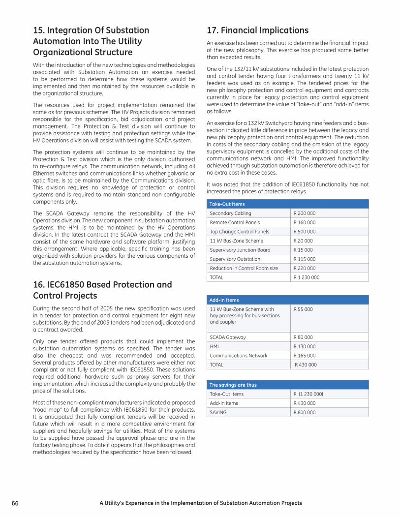
17.FinancialImplicationsAn exercise has been carried out to determine the financial impact of the new philosophy. This exercise has produced some better than expected results.
One of the 132/11 kV substations included in the latest protection and control tender having four transformers and twenty 11 kV feeders was used as an example. The tendered prices for the new philosophy protection and control equipment and contracts currently in place for legacy protection and control equipment were used to determine the value of “take-out” and “add-in” items as follows:
An exercise for a 132 kV Switchyard having nine feeders and a bus-section indicated little difference in price between the legacy and new philosophy protection and control equipment. The reduction in costs of the secondary cabling and the omission of the legacy supervisory equipment is cancelled by the additional costs of the communications network and HMI. The improved functionality achieved through substation automation is therefore achieved for no extra cost in these cases.
It was noted that the addition of IEC61850 functionality has not increased the prices of protection relays.
Take-OutItems
Secondary Cabling R 200 000
Remote Control Panels R 160 000
Tap Change Control Panels R 500 000
11 kV Bus-Zone Scheme R 20 000
Supervisory Junction Board R 15 000
Supervisory Outstation R 115 000
Reduction in Control Room size R 220 000
TOTAL R 1 230 000
Add-InItems
11 kV Bus-Zone Scheme withbay processing for bus-sectionsand coupler
R 55 000
SCADA Gateway R 80 000
HMI R 130 000
Communications Network R 165 000
TOTAL R 430 000
Thesavingsarethus
Take-Out Items R (1 230 000)
Add-In Items R 430 000
SAVING R 800 000
67AUtility’sExperienceintheImplementationofSubstationAutomationProjects
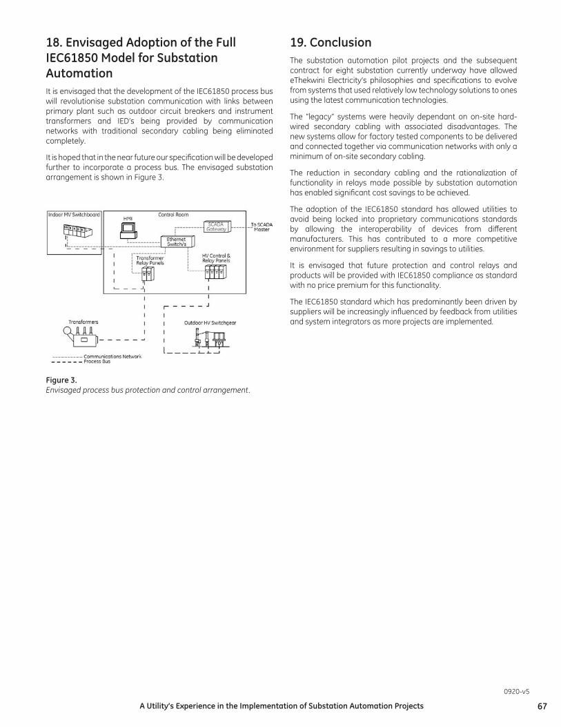
18.EnvisagedAdoptionoftheFullIEC61850ModelforSubstationAutomationIt is envisaged that the development of the IEC61850 process bus will revolutionise substation communication with links between primary plant such as outdoor circuit breakers and instrument transformers and IED’s being provided by communication networks with traditional secondary cabling being eliminated completely.
It is hoped that in the near future our specification will be developed further to incorporate a process bus. The envisaged substation arrangement is shown in Figure 3.
Figure3.Envisaged process bus protection and control arrangement.
0920-v5
19.ConclusionThe substation automation pilot projects and the subsequent contract for eight substation currently underway have allowed eThekwini Electricity’s philosophies and specifications to evolve from systems that used relatively low technology solutions to ones using the latest communication technologies.
The “legacy” systems were heavily dependant on on-site hard-wired secondary cabling with associated disadvantages. The new systems allow for factory tested components to be delivered and connected together via communication networks with only a minimum of on-site secondary cabling.
The reduction in secondary cabling and the rationalization of functionality in relays made possible by substation automation has enabled significant cost savings to be achieved.
The adoption of the IEC61850 standard has allowed utilities to avoid being locked into proprietary communications standards by allowing the interoperability of devices from different manufacturers. This has contributed to a more competitive environment for suppliers resulting in savings to utilities.
It is envisaged that future protection and control relays and products will be provided with IEC61850 compliance as standard with no price premium for this functionality.
The IEC61850 standard which has predominantly been driven by suppliers will be increasingly influenced by feedback from utilities and system integrators as more projects are implemented.