Embed Size (px)
Citation preview
A TOOLKIT FOR PROTOTYPING
INTERACTIVE ROBOT APPLICATIONS
インタラクティブなロボットアプリケーションの
プロトタイピング用ツールキット
by
Jun Kato
加藤 淳
A Master Thesis
修士論文
Submitted to
the Graduate School of the University of Tokyo
on February 8, 2011
in Partial Fulfillment of the Requirements
for the Degree of Master of Information Science and
Technology
in Computer Science
Thesis Supervisor: Takeo Igarashi 五十嵐 健夫
Associate Professor of Computer Science

ABSTRACT
Prototyping is critical for the development of interactive robot applications that handle
real-world tasks such as cooking and folding clothes according to user instructions. However,
prototyping such application is not easy for software programmers without prior knowledge
of robotics. To address this difficulty, we have repeated two cycles of iterative development of
Matereal, a toolkit for prototyping interactive robot applications. First version of the toolkit
provides application programming interfaces (APIs) for two-dimensional (2D) localization of
robots and objects on the floor of a fixed environment. It also provides APIs for high level 2D
locomotion of robots such as moving and pushing an object to a specified position. Second
version of the toolkit makes abstraction of high level locomotion tasks using 2D vector fields,
which allows intuitive control of movement of a robot on the floor. It also makes abstraction of
work flow of robot tasks using an activity diagram, which allows easy concurrent execution of
multiple tasks handled by multiple robots. The toolkit provides not only APIs for specifying
vector fields and activity diagrams but also graphical user interfaces which allow their direct
manipulation for debug purpose. This paper describes our iterative approach on making a
prototyping toolkit, validates its API design and other functionalities for prototyping support
and discusses its current limitation and future direction of the research.
論文要旨
ユーザの指示に従って料理や服畳みといった実世界におけるタスクを実行するインタラクティ
ブなロボットアプリケーションが実現しつつある.また,このような高度なアプリケーションの効
果的な開発には,プロトタイピングが重要である.しかし,ロボット工学の前提知識を持たない
ソフトウェアプログラマにとって,そのようなアプリケーションのプロトタイピングは簡単では
ない.我々は,この問題を解決するためにツールキット “Matereal”を開発した.開発にあたって
は,初版を評価実験の結果をもとに改訂し,さらに評価実験を行う反復的なアプローチを採った.
初版では,ロボットと物体の床面上での 2次元絶対座標を提供する位置検出 APIと,ロボットを
指定した絶対座標へ移動させたり物を押し運ばせる高レベルな移動指示 APIを提供した.次版で
は,高レベルな移動指示を 2次元のベクトル場で表す抽象化を行い,床面上での移動指示を直感
的に設計できるようにした.また,ロボットのタスクの実行手順をアクティビティ図で表す抽象
化を行い,複数のロボットによる複数のタスクの並列実行を簡単に指示できるようにした.さら
に,APIを通じてベクトル場や図式表現を動的に組み立てるプログラムを書けるようにしただけ
でなく,アプリケーションの実行中にこれらを直接操作できるデバッグ用の GUIも提供した.本
稿では,ロボットアプリケーションのプロトタイピングを可能にするツールキット開発における
我々の反復的アプローチを紹介しながら,策定した API及びその他のプロトタイピング支援機能
の妥当性を検証し,その応用範囲について議論する.
Acknowledgements
I would like to thank Associate Professor Takeo Igarashi for his patient support and
precise advice. I also thank my good neighbors who cared me so much. Furthermore,
I am grateful to all the members of Igarashi Laboratory and JST ERATO Igarashi
Design Interface Project for their cooperation.

Contents
1 Introduction 1
1.1 Research Goal . . . . . . . . . . . . . . . . . . . . . . . . . . . . . . . . 1
1.2 Research Outline . . . . . . . . . . . . . . . . . . . . . . . . . . . . . . 2
2 Related Work 3
2.1 Toolkit for Prototyping of Interactive System . . . . . . . . . . . . . . 3
2.2 Workflow Management . . . . . . . . . . . . . . . . . . . . . . . . . . . 4
2.3 Robot Programming . . . . . . . . . . . . . . . . . . . . . . . . . . . . 4
3 Experience with the First Version (Andy) 6
3.1 2D Localization . . . . . . . . . . . . . . . . . . . . . . . . . . . . . . . 6
3.2 2D Locomotion . . . . . . . . . . . . . . . . . . . . . . . . . . . . . . . 7
3.3 User Study . . . . . . . . . . . . . . . . . . . . . . . . . . . . . . . . . 8
3.3.1 Method . . . . . . . . . . . . . . . . . . . . . . . . . . . . . . . 8
3.3.2 Results . . . . . . . . . . . . . . . . . . . . . . . . . . . . . . . 8
3.4 Lessons Learned . . . . . . . . . . . . . . . . . . . . . . . . . . . . . . 11
3.4.1 Analogy of GUI . . . . . . . . . . . . . . . . . . . . . . . . . . . 12
3.4.2 Extendibility . . . . . . . . . . . . . . . . . . . . . . . . . . . . 13
3.4.3 Workflow Management . . . . . . . . . . . . . . . . . . . . . . . 14
4 Design of the Second Version (Matereal) 15
4.1 Robot and Task Abstraction . . . . . . . . . . . . . . . . . . . . . . . . 15
4.1.1 Resource Management . . . . . . . . . . . . . . . . . . . . . . . 15
4.1.2 Custom-made Robot Support . . . . . . . . . . . . . . . . . . . 16
4.2 Locomotion Control by 2D Vector Field . . . . . . . . . . . . . . . . . 17
4.3 Workflow Management by Activity Diagram . . . . . . . . . . . . . . . 19
4.4 Example Applications . . . . . . . . . . . . . . . . . . . . . . . . . . . 21
4.4.1 Bring It Here! . . . . . . . . . . . . . . . . . . . . . . . . . . . . 21
1
4.4.2 Robot Calligraphy . . . . . . . . . . . . . . . . . . . . . . . . . 22
4.5 User Experience . . . . . . . . . . . . . . . . . . . . . . . . . . . . . . 23
5 Discussion and Future Work 25
5.1 3D World and 2D Workspace . . . . . . . . . . . . . . . . . . . . . . . 25
5.2 Task-centric API Design . . . . . . . . . . . . . . . . . . . . . . . . . . 25
5.3 Human Beings as Part of System . . . . . . . . . . . . . . . . . . . . . 26
5.4 Formal Check of Activity Diagram . . . . . . . . . . . . . . . . . . . . 27
5.5 More Support for Prototyping . . . . . . . . . . . . . . . . . . . . . . . 27
5.6 Combination with Other Toolkits . . . . . . . . . . . . . . . . . . . . . 27
6 Conclusion 29
References 30
2
Chapter 1
Introduction
Various practical robot applications have been proposed to handle real-world tasks
such as cleaning [33, 39], folding clothes [34] and cooking [35] according to the user
instructions. However, most of them have been demonstrated for use cases with hard-
coded scenarios, which make it difficult to test other scenarios. Our goal is to enable
quick development of interactive robot applications so that developers can rapidly test
various scenarios in the prototyping phase.
Physical computing is related to robot applications in that both use sensors and
actuators in the real world. Progress in the physical computing field has accelerated
with the availability of toolkits for physical computing. Such toolkits allow more
programmers to prototype new user interfaces with new hardware without soldering
or complex microcomputer programming. We expect that research on interactive robot
applications will also benefit from an increase in the number of software programmers
who can prototype such applications with the support of toolkits.
1.1 Research Goal
By interactive robot applications, we mean applications such as follows: A robot visits
specified locations in sequence; a robot puts a tea cup containing a tea bag under a
kettle that pours hot water into the cup at the right time; multiple robots divide the
tasks for cleaning a room equally among themselves.
Such applications require multiple robots to handle multiple tasks, which are not
easy to implement for several reasons. First, high-level instructions like moving or
pushing an object to a specified location need to be executed as a combination of low-
level actuator commands continuously until the tasks are completed. Second, since
robot application prototyping is often done with custom-made robots whose hard-
1
ware might be updated during the development, the software architecture must be
flexible enough to deal with hardware changes. Third, the robot workflow, which
specifies when and which task is handled by each robot, must be managed properly
without causing deadlocks or other multithread-related problems. Our goal is to pro-
vide a development environment that can solve these three difficulties to let software
programmers rapidly prototype practical robot applications. We aim to lower the
threshold for robot programming rather than to raise the ceiling.
1.2 Research Outline
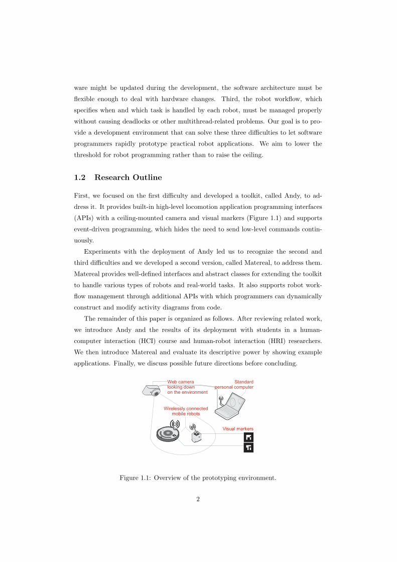
First, we focused on the first difficulty and developed a toolkit, called Andy, to ad-
dress it. It provides built-in high-level locomotion application programming interfaces
(APIs) with a ceiling-mounted camera and visual markers (Figure 1.1) and supports
event-driven programming, which hides the need to send low-level commands contin-
uously.
Experiments with the deployment of Andy led us to recognize the second and
third difficulties and we developed a second version, called Matereal, to address them.
Matereal provides well-defined interfaces and abstract classes for extending the toolkit
to handle various types of robots and real-world tasks. It also supports robot work-
flow management through additional APIs with which programmers can dynamically
construct and modify activity diagrams from code.
The remainder of this paper is organized as follows. After reviewing related work,
we introduce Andy and the results of its deployment with students in a human-
computer interaction (HCI) course and human-robot interaction (HRI) researchers.
We then introduce Matereal and evaluate its descriptive power by showing example
applications. Finally, we discuss possible future directions before concluding.
Visual markers
Web cameralooking downon the environment
Standardpersonal computer
Wirelessly connectedmobile robots
Figure 1.1: Overview of the prototyping environment.
2
Chapter 2
Related Work
2.1 Toolkit for Prototyping of Interactive System
Various user interface software tools have been developed in the past, which enable
rapid prototyping of user interfaces [26]. Rapid prototyping allows more iterations of
iterative design that is crucial for achieving higher-quality user interfaces [32]. There-
fore, toolkits for prototyping user interfaces play important role in the field of HCI.
Such toolkits have covered broad area of HCI including GUI [17], website design [27],
mobile applications [19] and Augmented Reality [22].
The recent trend of HCI puts more emphasis on physical interaction. The program-
mer is required to set up a new hardware configuration with sensors and actuators in
order to study a new physical interaction. A physical widget toolkit called Phid-
gets [11] was developed by Greenberg et al. Each Phiget is a package of a sensor or
actuator with a USB interface. It allows the programmer to design a new physical
interaction without soldering. Arduino [3] and other prototyping toolkits for micro-
computers lower the threshold for microcomputer programming. d.tools [12] is an
integrated development environment that supports the prototyping of such physical
interaction through not only programming and debugging but also observation of the
user’s interaction through recorded video.
As described above, when a new hardware device becomes available, new toolkits
to support interaction design with it are developed. The toolkits make an abstraction
of the hardware and hide messy things behind it. They strongly affect interaction
styles between the hardware and the user. Like the previous toolkits, our toolkit is
intended to explore possible interaction design for robots, which seem to be the most
complex kind of physical devices around computers.
3
2.2 Workflow Management
As we stated in our research goals, our toolkit is focused on how the programmer
can make the robots handle real-world tasks according to user instructions. These
instructions are usually specified synchronously through the user interface but are al-
ways executed asynchronously since real-world tasks take time to complete. Workflow
management of our toolkit is the feature that bridges the synchronous user input and
asynchronous task execution.
Research on workflow management in the field of computer science has its origin
in parallel computing on multiple processing elements. For example, Ackermann et
al. proposed dataflow languages [1] that use a petri-net to represent the dataflow in a
program. Subsequent studies include scientific workflow management systems such as
Kepler [21] and workflow languages for business process modeling such as YAWL [36].
An object-oriented modeling language that includes support for workflow management
was standardized as UML 1.0 [16]. The activity diagram is one of the UML diagrams
that can be used as a basic workflow specification language [7].
We chose the activity diagram to represent the robot workflow since its definition
is compact and easy to understand. Our toolkit is novel in the way that it provides
an executable implementation of an activity diagram that can express the workflows
of tasks in the real world.
2.3 Robot Programming
Many frameworks and toolkits for robot programming have been developed. Most of
them can be categorized roughly into three types according to their purposes.
The first type is middleware that provides hardware abstraction and functionality
for message passing between computers and robots in a distributed environment. For
example, Player [9] works as a server. Its clients can connect to and control any robots
in the distributed environment through defined interfaces. Robot Operating System
[30] constructs a peer-to-peer network in the environment and provides abstraction
of general-purpose services including robots and sensors, which is a similar concept
to Decentralized Software Services of Microsoft Robotics Developer Studio (MRDS)
[24]. RT-Middleware [2] uses a more strictly defined interface called RT component
for developing component-based robot systems, which is a similar concept to Orca [6].
On the other hand, our toolkit is not designed to become a software platform in a dis-
tributed environment like those, but is intended to provide a lightweight development
4
environment that can be executed on a personal computer with a simple hardware
setup and centralized network configuration in which all robots are connected to the
computer.
The second type is a library that is a collection of algorithms studied in the specific
research domain of robotics. For example, Carnegie Mellon Robot Navigation Toolkit
[25] provides a set of implementation of navigation algorithms. OpenSLAM [29] pro-
vides that of simultaneous localization and mapping (SLAM), which localize robots
with attached sensors in the environment during the construction of a map of the envi-
ronment. OpenCV [28] is a collection of computer-vision algorithms developed by the
maintainer of the Robot Operating System. Our toolkit does not focus on algorithms
like those.
The third type is toolkits for educational and entertainment purposes, which aim
to allow easy development of robot applications. Pyro [5] was developed to help
beginners to learn programming. It provides locomotion APIs for Python that can
specify the relative movement of a robot from the current position. Urbiscript for
the Urbi platform [4] is a script language that can specify the concurrent behaviors
of multiple robots. LEGO Mindstorms [18] provides a visual programming language
(VPL) based on ROBOLAB [8]. Topobo [31] is a robot whose local motion can be
specified by demonstrating the motion with the user’s hands on a real robot. Our
toolkit belongs to this category and differs from the others in that it provides two-
dimensional (2D) localization and locomotion APIs with easy hardware setup and that
it manages the robot workflow.
Some development environments try to provide features that cross these categories.
For example, MRDS provides an integrated development environment (IDE) based on
VPL. It is intended to be used by not only researchers but also hobbyists. Gostai
Studio [10], a commercial product built on top of the Urbi platform, also provides a
VPL-based IDE whose components are written in Urbiscript. In these environments, a
GUI-based diagram editor is used to orchestrate low-level programs written in a text-
based language. As a result, the diagram itself cannot be edited dynamically during
runtime and it is not easy to design the robot workflow during runtime. On the other
hand, applications made with our toolkit can construct and execute activity diagrams
dynamically according to user instructions. Our toolkit is novel in the way that it
allows the programmer to develop user interfaces for specifying the robot workflow.
5
Chapter 3
Experience with the First Version (Andy)
Andy was intended to provide high-level APIs and allow software programmers without
prior knowledge of robotics to command robots. It especially focused on the localiza-
tion and locomotion of robots and objects on the floor of the environment. It allowed
programmers to develop robot applications in a similar fashion to GUI applications
through event-driven programming.
3.1 2D Localization
Locomotion in the environment is one of the fundamental functionalities of a robot.
However, we do not have any absolute coordinates in the real world, and robot loco-
motion programming needs to start with robot localization.
In case of outdoor use, Global Positioning System (GPS) is generally used for
localization of robots. Odometory is used in combination with GPS when higher
accuracy is required. Otherwise, in case of indoor use, sensors attached to robots
such as laser range finders and ultrasonic sensors are usually used in combination
with odometory to achieve their self-localization. The localization process requires
map of the environment. The map needs to be recorded beforehand or calculated
through simultaneous localization and mapping (SLAM). Statically-recorded maps
cannot adapt to the change of the positions of the objects in the environment. SLAM
can deal with an unknown environment, but it takes time to construct the complete
map and is yet weak against the environmental change. In addition, it is not easy to
support all types of sensors or share the absolute coordinates among all entities in the
field. To avoid all these difficulties, commercially available motion-capture technology
is often deployed for stable demonstration of practical indoor robot applications.
Since our aim was to make a toolkit for prototyping, we assumed that the robots
6
move around on the floor of a fixed environment and provided 2D absolute coordinates
by means of a simple inexpensive hardware setup (Figure 1.1): visual markers attached
to the tops of robots and objects and a camera looking down on the environment.
Visual markers are detected from images captured by a camera. The positions of
corresponding entities are available to the programmers in either screen coordinates
of the captured images or real-world coordinates. This hardware setup works as a
simple motion capture system. The programmers can call methods of instances that
represent robots and objects in the real world to get their position information; they
can also add location listeners to them to get notified when the information is updated.
We used ARToolKit [14] markers for the visual markers; their detection algorithm is
available as an open-source Java library.
3.2 2D Locomotion
Andy supports mobile robots that can go forward, go backward, and rotate left and
right in place. Such robots are typically equipped with differential wheels. Given the
2D absolute coordinates, Andy provides three high-level locomotion APIs to program-
mers: move makes a robot go to a specified position, push makes it bring a specified
object to a specified position by pushing it, and visit makes it visit specified waypoints
in order. These APIs are provided as methods of instances that represent robots. The
programmers can know when the tasks are completed if they added event listeners to
the instances. If one of the locomotion methods is called when an already-assigned
task has not yet been completed, the old task is cancelled and the new task is assigned
to the robot.
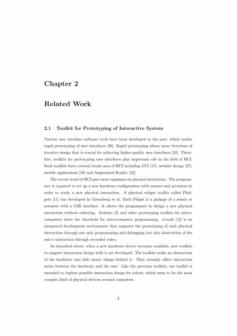
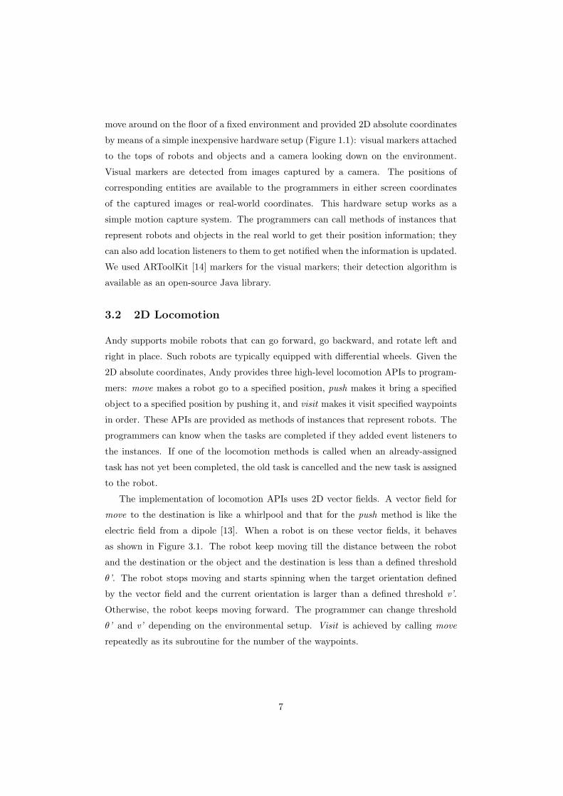
The implementation of locomotion APIs uses 2D vector fields. A vector field for
move to the destination is like a whirlpool and that for the push method is like the
electric field from a dipole [13]. When a robot is on these vector fields, it behaves
as shown in Figure 3.1. The robot keep moving till the distance between the robot
and the destination or the object and the destination is less than a defined threshold
θ’. The robot stops moving and starts spinning when the target orientation defined
by the vector field and the current orientation is larger than a defined threshold v’.
Otherwise, the robot keeps moving forward. The programmer can change threshold
θ’ and v’ depending on the environmental setup. Visit is achieved by calling move
repeatedly as its subroutine for the number of the waypoints.
7
Length of the vector: v
Angle of the vector andorientation of the robot: θ
StopSpin left
Goforward
Spin right
|θ| ≦θ’ ∧ dθ > 0dt
v > v’
θ > θ’
θ < -θ’
v ≦ v’
Threshold for v: v’Threshold for θ: θ’
Figure 3.1: State diagram of a robot on a vector field.
3.3 User Study
In this section, we briefly describe the method of the user study, present the results,
and introduce some of the resulting applications. Eleven groups formed of fifteen
graduate students enrolled in an HCI course [23] and three HRI researchers attended
the user study. We asked each student group and researcher to create an original robot
application by using alpha version of Andy. What made it alpha version was that push
API was not yet implemented at the point of the user study. As we will discuss later
in this chapter, push API was implemented additionally as part of Andy according to
the needs revealed after the user study.
3.3.1 Method
We told the students that their deliverables would not affect their course scores. Four-
teen students had never written a program for a robot before, while one student had
one experience of writing a program for a LEGO Mindstorms robot. We gave them
our homebuilt mobile robots, visual markers, web cameras, and Andy with a robot
class for the robots. The robot is wirelessly connected to a host computer via Blue-
tooth. It measures 7.5 x 8.8 x 6.5 [cm] and is driven by two stepping motors. Visual
markers were 5.5 [cm] square. Cameras could capture images with 800 x 600 [pixels]
at 30 [fps]. The HRI researchers prepared the robots and other hardware setup by
themselves, so we only provided the software with a little customization to handle
their custom hardware.
3.3.2 Results
We confirmed that all the student groups and researchers had successfully developed
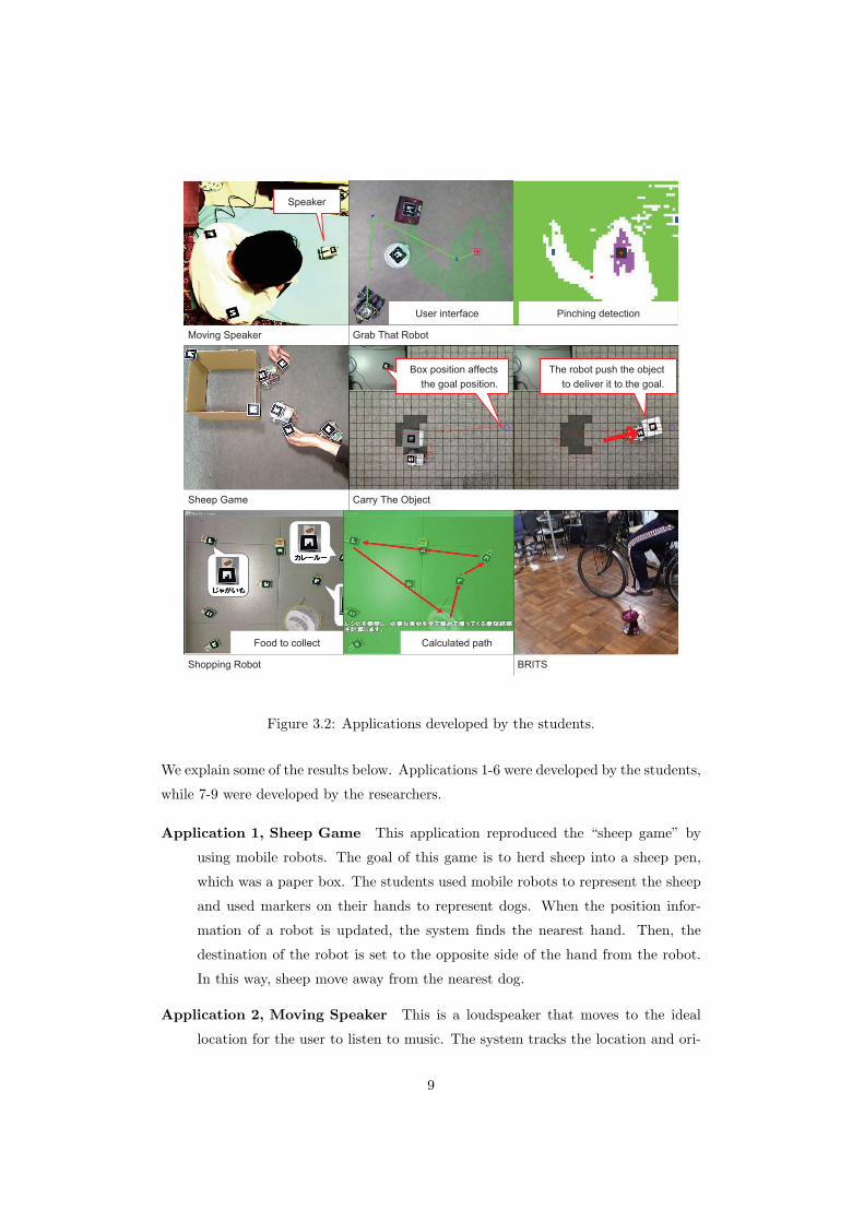
robot applications with 2D localization and locomotion APIs working fine (Figure 3.2).
8
BRITSShopping Robot
Food to collect Calculated path
Carry The Object
Box position affectsthe goal position.
The robot push the objectto deliver it to the goal.
Sheep Game
Grab That Robot
User interface Pinching detection
Moving Speaker
Speaker
Figure 3.2: Applications developed by the students.
We explain some of the results below. Applications 1-6 were developed by the students,
while 7-9 were developed by the researchers.
Application 1, Sheep Game This application reproduced the “sheep game” by
using mobile robots. The goal of this game is to herd sheep into a sheep pen,
which was a paper box. The students used mobile robots to represent the sheep
and used markers on their hands to represent dogs. When the position infor-
mation of a robot is updated, the system finds the nearest hand. Then, the
destination of the robot is set to the opposite side of the hand from the robot.
In this way, sheep move away from the nearest dog.
Application 2, Moving Speaker This is a loudspeaker that moves to the ideal
location for the user to listen to music. The system tracks the location and ori-
9
entation of the user by using two visual markers mounted on the user’s shoulders
and moves the speaker mounted on the robot to a location in front of the user.
Application 3, Grab That Robot This is an application of vision-based detec-
tion of pinching gesture user interface [38]. The user grabs the robot virtually
by making a circle with two fingers in front of a camera and moves the robot to
a different position by moving the finger circle to the target position. The user’s
hand appears translucent in the ceiling camera view.
Application 4, Carry the Object The student implemented an algorithm to de-
liver an object to the specified position by himself for this application. This
application uses a miniature box on a desk as a proxy of a large box in the envi-
ronment. When a user moves the miniature box, the robot brings the large box
to the corresponding position. The original algorithm works as follows: First,
the robot calculates paths to the position which is on the opposite side of the
box from the final destination. Next, it moves toward the destination. Then, the
box is pushed by the robot and gets near to the destination. When the robot is
no longer on the opposite side of the box from the destination, this procedure
reruns from the first. By repeating this procedure, the robot can bring the box
to the destination.
Application 5, Shopping Robot In this application, a robot was added extended
arms to gathers food for making a dinner. Each food item was associated with a
marker and placed on the table randomly. The system calculated a suitable path
i.e., a list of destination positions for gathering the food, and the robot moved
around on the table by visiting all the destinations on the list. When the robot
finished its journey, all foods were held in its arms.
Application 6, Bicycle-robot Tele-operation System The system only used
low-level commands to control immediate movement of the robot. The student
made an original rotary-encoder to measure the rotation of the bicycle wheel.
This information was used for indicating the speed of the robot. The student also
put another sensor on the bicycle handle to indicate the direction of the robot.
When the user rode and pedaled a stationary bicycle, the robot ran on the floor.
Other examples which only used low-level commands include one which used Wii
remote (an accelerometer) to navigate the robot in a leaning way and one which
used speech recognition to navigate the robot by speaking “left”, “right”, and
so on.
10

Application 7, Multi-touch Interface for Multiple Mobile Robots This is a
multi-touch interface with a top-down view of the environment for controlling
multiple mobile robots simultaneously [15]. The top-down view is overlaid with
a virtual flow field. This flow field is used to command the robot associated
with a specific location in the field. The user manipulates the flow field, and
the robot moves in accordance with the flow. The flow field is stored as vectors
specified at 2-dimensional grid points. When the user touches his hand to the
display and moves that hand, the vector values stored at nearby grid points are
updated. The direction in which each robot will go is determined by the sum of
vectors at nearby grid points. Users touch and move their hands on the screen to
specify the 2-dimensional vector field, and all the robots move along the vector
field. This application used localization APIs but high-level locomotion APIs of
Andy, since locomotion strategies of the robots cannot be implemented with the
existing locomotion APIs.
Application 8, Sketch and Run This is an interface for commanding a Roomba
robot by sketching the robot’s behaviors and actions on a top-down view of the
environment [33]. The user can draw a path to be followed, lasso an area to be
cleaned, and draw gestures anywhere on the screen to pause/resume/stop these
behaviors or make the robot return to its base. A Roomba robot is implemented
as a Roomba class for Andy that has a method for cleaning around the robot
other than the default localization and locomotion APIs.
Application 9, Cooky This application cooks a meal by pouring various ingredi-
ents into a saucepan on an induction heating cooker and adjusts the heating level
according to the user’s instructions [35]. The researcher developed three types
of customized small mobile robots: one for transporting ingredients on plates,
one for transporting seasonings in bottles, and one for stirring the pan. They
were implemented as different types of robot classes: each had its own method
for its original functionalities other than the default APIs.
3.4 Lessons Learned
In this subsection, we explain what we learned from the deployment of Andy that led
us to make the revisions for the second version.
11
3.4.1 Analogy of GUI
The set of localization and locomotion APIs on the two-dimensional absolute coor-
dinates was the key feature of Andy. It was used effectively to prototype interesting
applications. Its hardware setup was easily deployed on the desktop and on the floor
of a room with cameras attached at heights of about 50 [cm] and 200 [cm], respec-
tively. The strategy for move is scale-invariant since it uses only angle information to
switch between going forward and rotating. As a result, locomotion tasks could be
executed robustly on both the desktop and the floor using visual markers 5.5 [cm] and
11.5 [cm] square, respectively, though parameter optimization for each type of robot
was needed. For example, since our original small robot moves at a lower speed than
Roomba and is capable of moving more precisely, a threshold of the distance from the
destination to judge completion of move for our original robot should be set smaller
than for a Roomba robot. These parameters could be also affected by the robustness
of the localization functionality, which depends on various environmental factors such
as illumination brightness.
At the point of the user study, we provided move and visit APIs but push API,
which were achieved by two applications through additional software implementation
(Carry the Object) and hardware attachment of extended arms (Shopping Robot).
These two applications led us to notice that there were more applications which could
potentially benefit from push API. For example, Grab That Robot user interface could
also be used to “Grab That Object” by pushing the object to the specified location.
Sketch and Run user could temporarily get rid of obstacles in the cleaning area. In
addition, we noticed that the set of APIs without push was out of balance; while the
programmer could get position of robots and objects, they could only set position
of robots but objects. Therefore, we additionally implemented push API as a part
of Andy which allowed the programmer to get and set position of both robots and
objects.
It is notable that many programmers used the top-down view of the environment
for the GUI to give instructions to the robots. There were various different kinds of
applications. While we aimed to provide APIs using the analogy of GUI, the results
seemed to imply further correspondence between computer desktop and the real world:
window, icon, menu and pointer (WIMP) correspond to “camera”, “visual marker”,
“list of available tasks” and “robot”. First, a window displays objects of interest, while
a camera of Andy frames real-world objects of interest. Second, an icon represents
an object such as a file, a folder, program, or command and indicates that it can be
12
operated (i.e. opened or executed) by the user, while a visual marker represents a
real-world object which is managed by Andy and can be handled by an application in
its intended way. Third, a menu in GUI shows available tasks and allows the user to
choose one of them, while Andy provides a list of available tasks and a user interface
application implemented with Andy allows the user to command one of them. Forth
and finally, a mouse pointer shows the target position of direct manipulation. In other
words, the mouse pointer manipulates an object at its position when commanded by
the user. It corresponds to a robot in the real world which can manipulate real-world
objects at its position. The manipulation task is not limited to onsite tasks such as
cleaning the floor but also includes mobility tasks such as delivering an object from one
place to another which corresponds to drag and drop operation in GUI. Recent desktop
operating systems have support for multi-touch and may have multiple pointers, which
can be thought to correspond to multiple robots. As we have discussed, a set of
a camera (viewpoint), visual markers and robots can be thought of as not only an
inexpensive hardeware setup, but also a fundamental set for real-world programming.
3.4.2 Extendibility
All of the students completed their projects, but their results seemed to be limited by
the hardware and software specifications. Since we provided the robots and the toolkit
as one package for simplicity, they were not designed to be extended by the students,
and their technical specifications were not open. As a result, the robots were never
extended mechanically, though the Shopping Robot group attached paper-made arms
to a robot to gather food. It was neither possible to newly define locomotion strategies
other than the predefined push hand move APIs, which was demanded by the Sheep
Game group.
The HRI researchers benefited from the extra features of the robots by using ex-
tended robot classes, but we observed that the researcher who made three types of
robots for Cooky modified the robot classes iteratively to handle tasks robustly during
his development phase. The multi-touch interface could be implemented more easily
if new locomotion strategies for robots can be defined on top of Andy.
These observations revealed the importance of the extra features for the robot built
on top of the basic locomotion features. We felt that the toolkit needed to be extendible
to adapt to new hardware configurations and to implement new software routines
for handling tasks. It should be easy to extend the toolkit so that the programmer
can easily carry out the iterative development process of prototyping. Moreover, to
13
make the toolkit capable of assigning multiple tasks to a robot like streaming the
video captured by its head-mounted camera while moving to the destination, resource
management is required for safe program execution.
3.4.3 Workflow Management
The robot workflows were quite simple in all of the applications except for Cooky.
Applications 1 and 2 called move continuously during their runtime. Applications 3
and 4 called visit once when the route to visit had been decided. Application 5 called
move, visit, and other APIs every time the user commanded. Event listeners for tasks
were not used at all for these.
Unlike the other applications, Cooky created a thread to each task to manage
the task workflow. Each thread started the task assigned to a robot at the right time.
Though this is a very simple solution for workflow management, it is problematic since
there is no guarantee that multiple threads never try to control the same robot at the
same time; for example, moving its wheels and swinging its arm. Such a conflict might
lead to the program crashing, which was really observed to happen in the application.
In addition, the programmer is required to take care of general multithread-related
issues such as synchronization deadlocks.
We considered that the lack of active support for workflow management resulted in
most of the applications not dealing with complex workflows, and the solution chosen
by the programmer of Cooky seemed not to be the best one. Therefore, we were
motivated to provide APIs for the workflow management.
14
Chapter 4
Design of the Second Version (Matereal)
Matereal was developed to meet the needs that arose after the deployment of the first
version. It keeps the features of 2D absolute coordinates, but differs in its software
architecture, which has enough extendibility, and in its support for workflow manage-
ment using activity diagrams.
4.1 Robot and Task Abstraction
The API design of Andy forced the programmer to write a task routine in a robot
class, which made it difficult to share the routine among different robot types. Instead,
Matereal provides abstraction of both of robots and tasks by predefined interfaces and
abstract classes. Every type of robot is implemented as a class, which has a set of
function units called “resources”. Every type of task like pushing an object is also
implemented as a class but not as a method of a robot class. Its instance requests one
or more resources to carry out the task.
4.1.1 Resource Management
Some types of tasks need to obtain the resources of a robot exclusively, and Matereal
manages the use of such resources. For example, the output to an actuator should be
controlled from at most one task at a time, but observation of the output does not
need exclusive control. When multiple tasks try to control an actuator, the program
might produce an error. For such a case, interfaces for observing and controlling the
output are defined separately as Wheels and WheelsController. An interface that re-
quires exclusive control must extend the ExclusiveResource interface, whose instance
is managed properly by the toolkit to avoid any conflict. With this resource manage-
ment support, the programmer can safely assign to a robot multiple tasks that do not
15
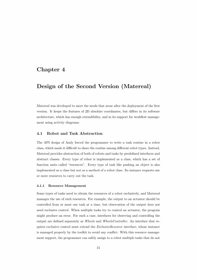
conflict with each other. For example, Code 4.1 makes a robot with a head-mounted
camera capture video while moving forward.
Code 4.1: Multiple tasks handled simultaneously by a robot.Robot robot = new NetTansor ( ) ;
GoForward g f = new GoForward ( ) ;
Capture cap = new Capture ( ) ;
i f ( g f . a s s i gn ( robot ) ) g f . s t a r t ( ) ;
i f ( cap . a s s i gn ( robot ) ) {cap . addImageListener (new ImageListener ( ) {
public void imageUpdated ( Image image ) {// Code to handle captured image here .
}} ) ;
cap . s t a r t ( ) ;
}// Tasks continue t i l l s top () of the tasks i s c a l l e d .
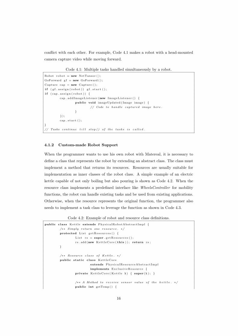
4.1.2 Custom-made Robot Support
When the programmer wants to use his own robot with Matereal, it is necessary to
define a class that represents the robot by extending an abstract class. The class must
implement a method that returns its resources. Resources are usually suitable for
implementation as inner classes of the robot class. A simple example of an electric
kettle capable of not only boiling but also pouring is shown as Code 4.2. When the
resource class implements a predefined interface like WheelsController for mobility
functions, the robot can handle existing tasks and be used from existing applications.
Otherwise, when the resource represents the original function, the programmer also
needs to implement a task class to leverage the function as shown in Code 4.3.
Code 4.2: Example of robot and resource class definitions.public c lass Kett l e extends PhysicalRobotAbstractImpl {
/∗∗ Simply return one resource . ∗/protected L i s t getResources ( ) {
L i s t r s = super . getResources ( ) ;
r s . add (new Kett leCore ( this ) ) ; return r s ;
}
/∗∗ Resource c l a s s of Ket t l e . ∗/public stat ic c lass Kett leCore
extends Phys ica lResourceAbstractImpl
implements Exclus iveResource {private Kett leCore ( Kett l e k ) { super ( k ) ; }
/∗∗ A Method to rece ive sensor value of the k e t t l e . ∗/public int getTemp ( ) {
16
getConnector ( ) . wr i t e ( ” t ” ) ;
return getConnector ( ) . r eadInt ( ) ;
}
/∗∗ Methods to change operat ing mode of the k e t t l e . ∗/public void heat ( ) { getConnector ( ) . wr i t e ( ”h” ) ; }public void stop ( ) { getConnector ( ) . wr i t e ( ” s ” ) ; }
// Other methods to contro l the k e t t l e are abbrev ia ted .
}}
Code 4.3: Example of a task class definition.public c lass Boi l extends TaskAbstractImpl {
private Kett leCore core ;
/∗∗ Request Kett leCore resource . ∗/public L i s t getRequirements ( ) {
L i s t resourceTypes = super . getRequirements ( ) ;
resourceTypes . add ( Kett leCore . class ) ;
return resourceTypes ;
}
/∗∗ Store resource to a member var i a b l e and s t a r t heat ing . ∗/protected void onStart ( ) {
core = getResourceMap ( ) . get ( Kett leCore . class ) ;
core . heat ( ) ;
}
/∗∗ Heat t i l l the temperature exceeds 90 [ deg C] . ∗/public void run ( ) {
i f ( core . getTemp ( ) > 90) f i n i s h ( ) ;
}}
4.2 Locomotion Control by 2D Vector Field
To meet the needs for defining new locomotion strategies of robots observed in the
user study of Andy, Matereal provides abstraction of locomotion strategies using vec-
tor fields on top of the task abstraction. When the vector field for a robot reflects
the position of other entities, it can be used for simple cooperation tasks as shown in
Figure 4.1: (a) A vector field falling into the position behind a robot will make another
robot follow the robot; (b) when multiple push tasks for transportation of the same
object to the same location are assigned to multiple robots, the robots push the object
directly or indirectly by pushing other robot pushing the object. As a result, cooper-
ative transportation of the object by multiple robots can be successfully achieved as
17
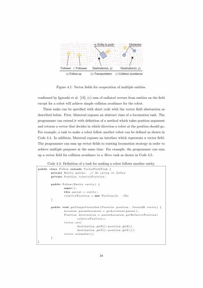
(b) Transportation (c) Collision avoidance(a) Follow-up
Destination(x, y)
e: Entity to push Obstacles
r: FolloweeFollower Destination(x, y)
Figure 4.1: Vector fields for cooperation of multiple entities.
confirmed by Igarashi et al. [13]; (c) sum of radiated vectors from entities on the field
except for a robot will achieve simple collision avoidance for the robot.
These tasks can be specified with short code with the vector field abstraction as
described below. First, Matereal exposes an abstract class of a locomotion task. The
programmer can extend it with definition of a method which takes position argument
and returns a vector that decides in which direction a robot at the position should go.
For example, a task to make a robot follow another robot can be defined as shown in
Code 4.4. In addition, Matereal exposes an interface which represents a vector field.
The programmer can sum up vector fields to existing locomotion strategy in order to
achieve multiple purposes at the same time. For example, the programmer can sum
up a vector field for collision avoidance to a Move task as shown in Code 4.5.
Code 4.4: Definition of a task for making a robot follows another entity.public c lass Follow extends VectorFie ldTask {
private Entity parent ; // An en t i t y to f o l l ow
private Pos i t i on r e l a t i v eP o s i t i o n ;
public Follow ( Entity en t i t y ) {super ( ) ;
this . parent = en t i t y ;
r e l a t i v eP o s i t i o n = new Pos i t i on (0 , −70);
}
public void getUniqueVectorOut ( Pos i t i on pos i t i on , Vector2D vector ) {Locat ion parentLocat ion = getLocat ion ( parent ) ;
Pos i t i on d e s t i n a t i on = parentLocat ion . g e tRe l a t i v ePo s i t i on (
r e l a t i v eP o s i t i o n ) ;
vec to r . s e t (
d e s t i n a t i on . getX()− po s i t i o n . getX ( ) ,
d e s t i n a t i on . getY()− po s i t i o n . getY ( ) ) ;
vec to r . normal ize ( ) ;
}}
18
Code 4.5: Code for achieving collision avoidance during locomotion.Task moveWithoutCol l is ion = new Move( hakoniwa . screenToReal ( goa l ) ) ;
moveWithoutCol l is ion . add (new Col l i s i onAvo idance ( robot ) ) ;
i f ( moveWithoutCol l is ion . a s s i gn ( robot ) )
moveWithoutCol l is ion . s t a r t ( ) ;
4.3 Workflow Management by Activity Diagram
With the robot and task abstraction, the programmer can easily assign one or more
tasks to a robot. However, practical applications often require multiple tasks to be
handled in sequence or require multiple robots to cooperate with each other. Matereal
abstracts these kinds of scenarios as activity diagrams and provides the APIs listed
in Table 4.1 to construct and execute the diagrams. Since real-world applications
often face the need to handle timeouts, we provide the TimeoutTransition class for
convenience: it extends the Transition class and activates when the specified time until
the source task is started has passed.
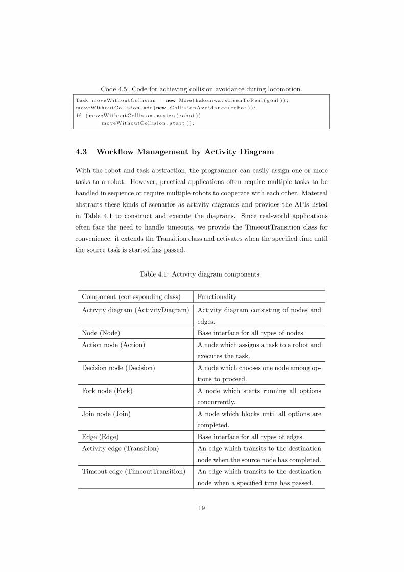
Table 4.1: Activity diagram components.
Component (corresponding class) Functionality
Activity diagram (ActivityDiagram) Activity diagram consisting of nodes and
edges.
Node (Node) Base interface for all types of nodes.
Action node (Action) A node which assigns a task to a robot and
executes the task.
Decision node (Decision) A node which chooses one node among op-
tions to proceed.
Fork node (Fork) A node which starts running all options
concurrently.
Join node (Join) A node which blocks until all options are
completed.
Edge (Edge) Base interface for all types of edges.
Activity edge (Transition) An edge which transits to the destination
node when the source node has completed.
Timeout edge (TimeoutTransition) An edge which transits to the destination
node when a specified time has passed.
19
The activity diagram is a specification representing a program’s workflow that is
defined in Unified Modeling Language (UML) 1.0 [16]. It can be thought of as an
extension of the flowchart whose difference is that multiple flows can be executed
concurrently. The use of the data structure representing the workflow is expected to
relieve the programmer from messy multithread programming. The programmer can
add event listeners to diagram nodes or to the diagrams themselves to get notified
when the program enters or leaves the nodes.
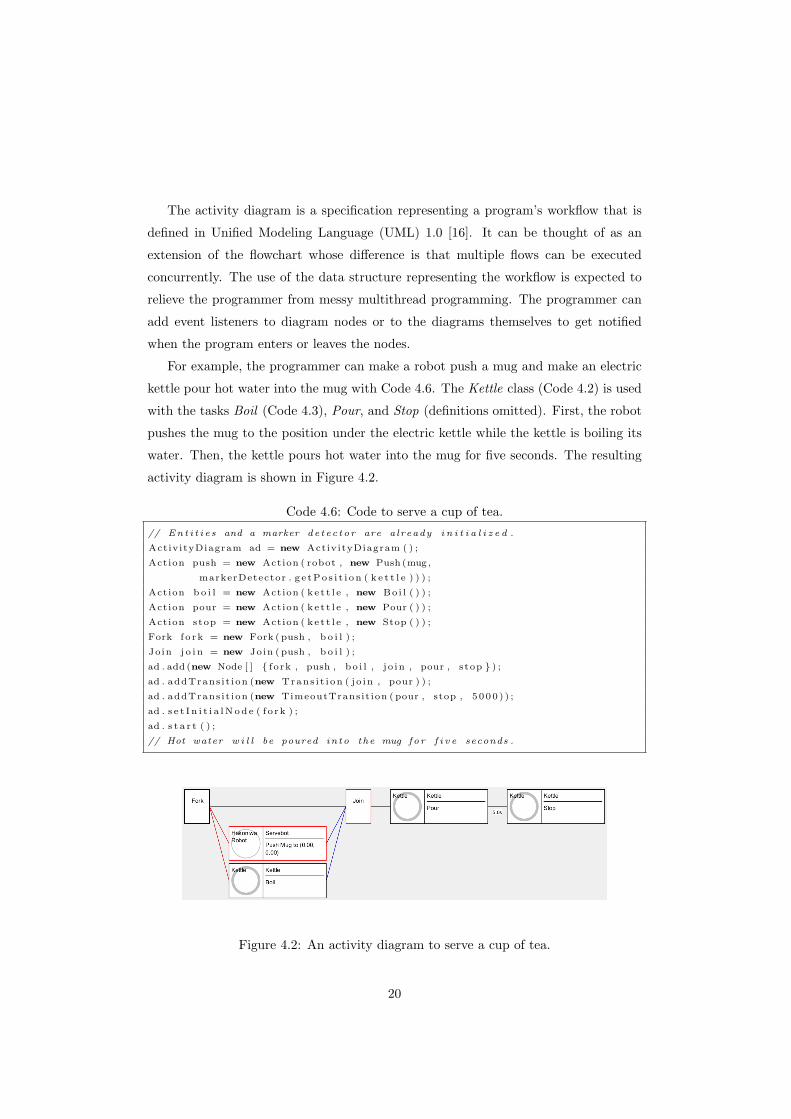
For example, the programmer can make a robot push a mug and make an electric
kettle pour hot water into the mug with Code 4.6. The Kettle class (Code 4.2) is used
with the tasks Boil (Code 4.3), Pour, and Stop (definitions omitted). First, the robot
pushes the mug to the position under the electric kettle while the kettle is boiling its
water. Then, the kettle pours hot water into the mug for five seconds. The resulting
activity diagram is shown in Figure 4.2.
Code 4.6: Code to serve a cup of tea.// Ent i t i e s and a marker de tec tor are already i n i t i a l i z e d .
ActivityDiagram ad = new ActivityDiagram ( ) ;
Action push = new Action ( robot , new Push (mug ,
markerDetector . g e tPo s i t i on ( k e t t l e ) ) ) ;
Action b o i l = new Action ( ke t t l e , new Boi l ( ) ) ;
Action pour = new Action ( ke t t l e , new Pour ( ) ) ;
Action stop = new Action ( ke t t l e , new Stop ( ) ) ;
Fork fo rk = new Fork ( push , b o i l ) ;
Join j o i n = new Join ( push , b o i l ) ;
ad . add (new Node [ ] { fork , push , bo i l , j o in , pour , stop } ) ;
ad . addTrans i t ion (new Trans i t i on ( jo in , pour ) ) ;
ad . addTrans i t ion (new TimeoutTransit ion ( pour , stop , 5000 ) ) ;
ad . s e t I n i t i a lNod e ( f o rk ) ;
ad . s t a r t ( ) ;
// Hot water w i l l be poured into the mug for f i v e seconds .
Figure 4.2: An activity diagram to serve a cup of tea.
20
As seen above, activity diagrams are not hard-coded and provided statically like
in pure VPL but generated dynamically from code during runtime. At the same
time, Matereal provides a graph editor called “activity diagram editor” that visualizes
currently running activity diagrams, like those in Figure 4.2. It allows the programmer
to monitor the status of the robots. This is helpful for debugging since the programmer
can figure out where in the source code the program is running. It also allows the
programmer to edit the diagram to test another workflow for the robot on runtime,
which is desirable for rapid prototyping.
4.4 Example Applications
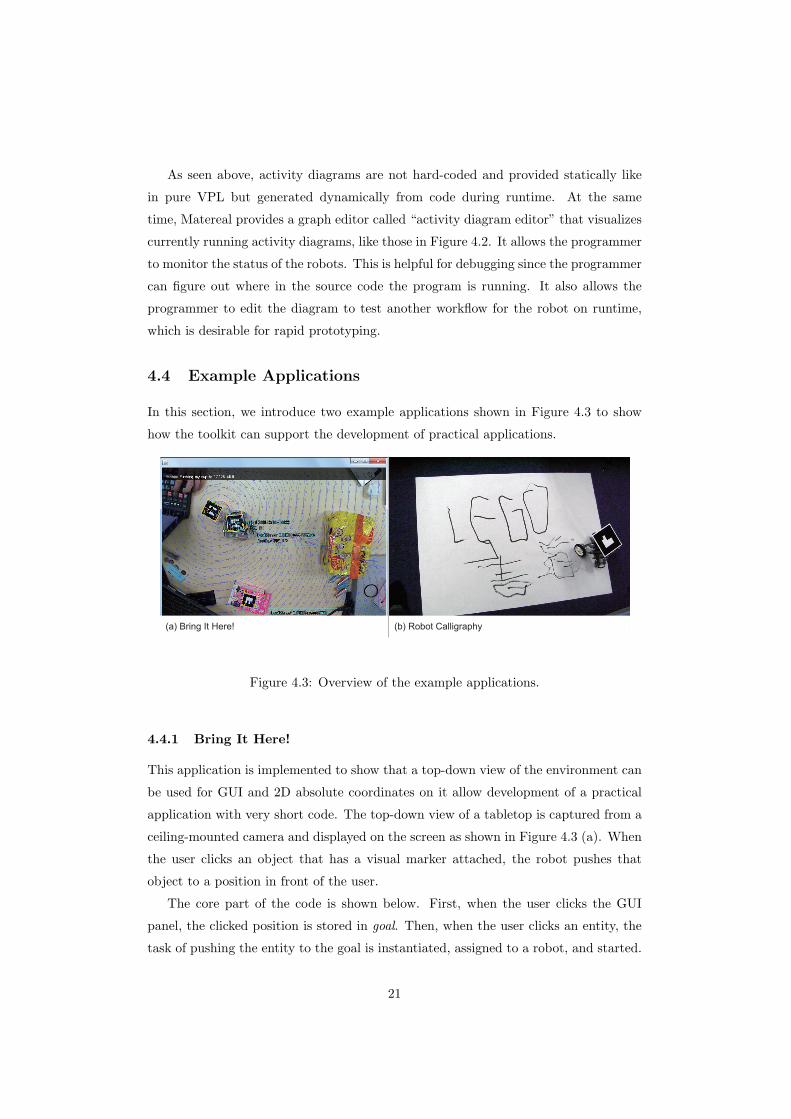
In this section, we introduce two example applications shown in Figure 4.3 to show
how the toolkit can support the development of practical applications.
(b) Robot Calligraphy(a) Bring It Here!
Figure 4.3: Overview of the example applications.
4.4.1 Bring It Here!
This application is implemented to show that a top-down view of the environment can
be used for GUI and 2D absolute coordinates on it allow development of a practical
application with very short code. The top-down view of a tabletop is captured from a
ceiling-mounted camera and displayed on the screen as shown in Figure 4.3 (a). When
the user clicks an object that has a visual marker attached, the robot pushes that
object to a position in front of the user.
The core part of the code is shown below. First, when the user clicks the GUI
panel, the clicked position is stored in goal. Then, when the user clicks an entity, the
task of pushing the entity to the goal is instantiated, assigned to a robot, and started.
21
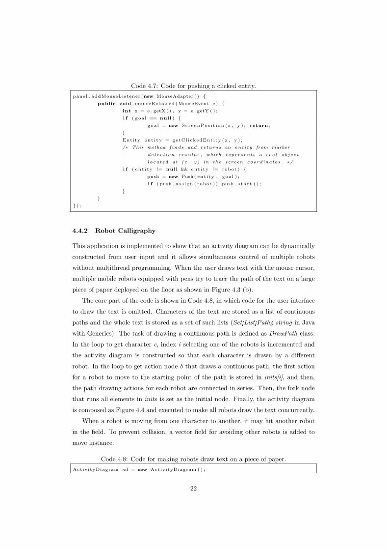
Code 4.7: Code for pushing a clicked entity.panel . addMouseListener (new MouseAdapter ( ) {
public void mouseReleased (MouseEvent e ) {int x = e . getX ( ) , y = e . getY ( ) ;
i f ( goa l == null ) {goa l = new ScreenPos i t i on (x , y ) ; return ;
}Entity en t i t y = getCl i ckedEnt i ty (x , y ) ;
/∗ This method f inds and returns an en t i t y from marker
de tec t ion re su l t s , which represents a rea l ob j e c t
loca ted at (x , y ) in the screen coordinates . ∗/i f ( en t i t y != null && ent i t y != robot ) {
push = new Push ( ent i ty , goa l ) ;
i f ( push . a s s i gn ( robot ) ) push . s t a r t ( ) ;
}}
} ) ;
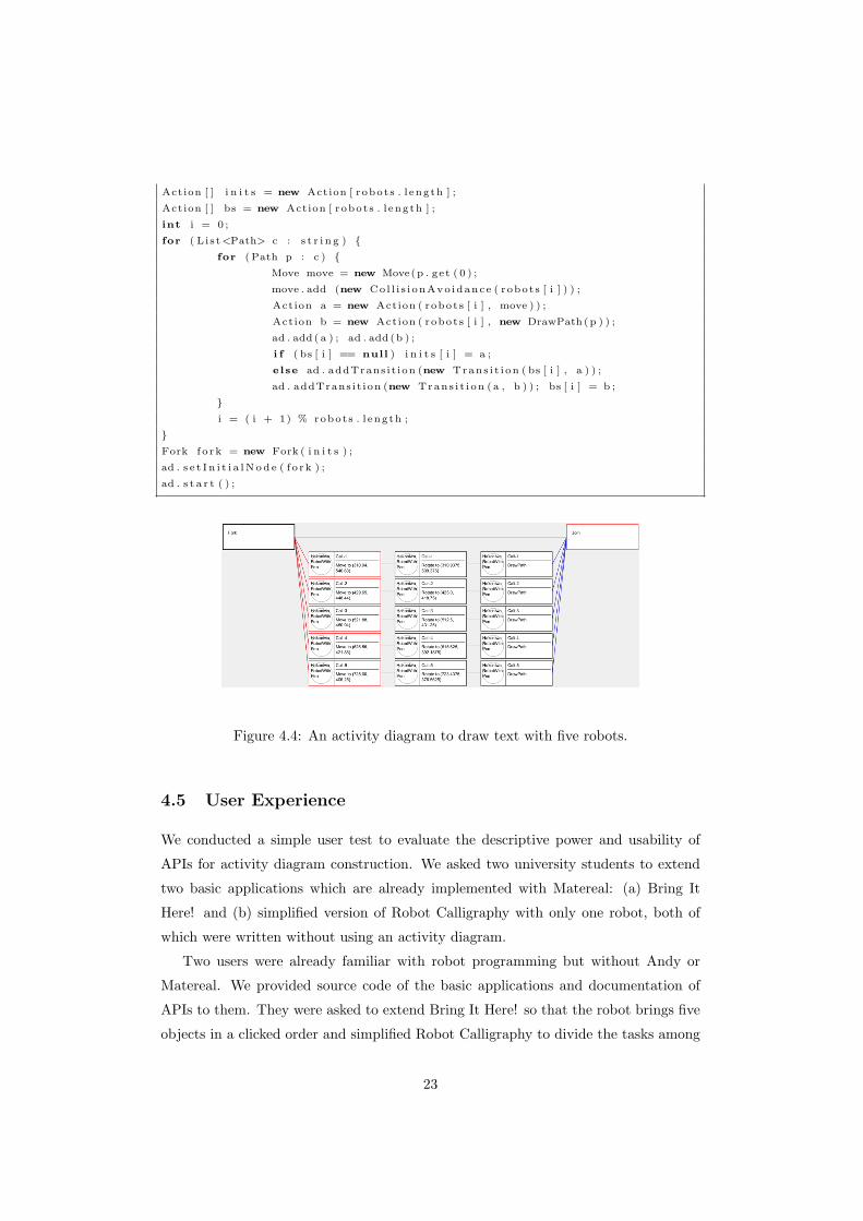
4.4.2 Robot Calligraphy
This application is implemented to show that an activity diagram can be dynamically
constructed from user input and it allows simultaneous control of multiple robots
without multithread programming. When the user draws text with the mouse cursor,
multiple mobile robots equipped with pens try to trace the path of the text on a large
piece of paper deployed on the floor as shown in Figure 4.3 (b).
The core part of the code is shown in Code 4.8, in which code for the user interface
to draw the text is omitted. Characters of the text are stored as a list of continuous
paths and the whole text is stored as a set of such lists (Set¡List¡Path¿ string in Java
with Generics). The task of drawing a continuous path is defined as DrawPath class.
In the loop to get character c, index i selecting one of the robots is incremented and
the activity diagram is constructed so that each character is drawn by a different
robot. In the loop to get action node b that draws a continuous path, the first action
for a robot to move to the starting point of the path is stored in inits[i], and then,
the path drawing actions for each robot are connected in series. Then, the fork node
that runs all elements in inits is set as the initial node. Finally, the activity diagram
is composed as Figure 4.4 and executed to make all robots draw the text concurrently.
When a robot is moving from one character to another, it may hit another robot
in the field. To prevent collision, a vector field for avoiding other robots is added to
move instance.
Code 4.8: Code for making robots draw text on a piece of paper.ActivityDiagram ad = new ActivityDiagram ( ) ;
22
Action [ ] i n i t s = new Action [ robots . l ength ] ;
Action [ ] bs = new Action [ robots . l ength ] ;
int i = 0 ;
for ( L ist<Path> c : s t r i n g ) {for (Path p : c ) {
Move move = new Move(p . get ( 0 ) ;
move . add (new Col l i s i onAvo idance ( robots [ i ] ) ) ;
Action a = new Action ( robots [ i ] , move ) ) ;
Action b = new Action ( robots [ i ] , new DrawPath (p ) ) ;
ad . add ( a ) ; ad . add (b ) ;
i f ( bs [ i ] == null ) i n i t s [ i ] = a ;
else ad . addTrans i t ion (new Trans i t i on ( bs [ i ] , a ) ) ;
ad . addTrans i t ion (new Trans i t i on (a , b ) ) ; bs [ i ] = b ;
}i = ( i + 1) % robots . l ength ;
}Fork fo rk = new Fork ( i n i t s ) ;
ad . s e t I n i t i a lNod e ( f o rk ) ;
ad . s t a r t ( ) ;
Figure 4.4: An activity diagram to draw text with five robots.
4.5 User Experience
We conducted a simple user test to evaluate the descriptive power and usability of
APIs for activity diagram construction. We asked two university students to extend
two basic applications which are already implemented with Matereal: (a) Bring It
Here! and (b) simplified version of Robot Calligraphy with only one robot, both of
which were written without using an activity diagram.
Two users were already familiar with robot programming but without Andy or
Matereal. We provided source code of the basic applications and documentation of
APIs to them. They were asked to extend Bring It Here! so that the robot brings five
objects in a clicked order and simplified Robot Calligraphy to divide the tasks among
23
five robots. One user was asked to use only event listeners (event-driven programming)
for the first application and activity diagram for the second application. The other
was asked to use activity diagram and then event listeners.
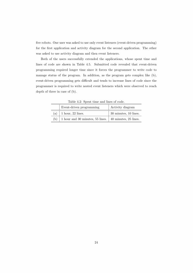
Both of the users successfully extended the applications, whose spent time and
lines of code are shown in Table 4.5. Submitted code revealed that event-driven
programming required longer time since it forces the programmer to write code to
manage status of the program. In addition, as the program gets complex like (b),
event-driven programming gets difficult and tends to increase lines of code since the
programmer is required to write nested event listeners which were observed to reach
depth of three in case of (b).
Table 4.2: Spent time and lines of code.
Event-driven programming Activity diagram
(a) 1 hour, 22 lines. 30 minutes, 10 lines.
(b) 1 hour and 30 minutes, 55 lines. 40 minutes, 25 lines.
24
Chapter 5
Discussion and Future Work
5.1 3D World and 2D Workspace
Matereal supports only 2D activities of mobile robots. While it is possible to extend
the framework to three dimensions, we decided to focus on two dimensions for several
reasons. First, it is simply much easier to understand 2D coordinates and develop
applications in them because software programmers are familiar with GUIs that use 2D
coordinates and whose standard input and output devices are capable of processing 2D
information. Second, 2D information is often sufficient to represent the global positions
of the most relevant entities including the robots, objects, and users because all of them
usually reside on a 2D surface such as the desktop or floor. Our assumption is that
global locomotion tasks can be handled in 2D coordinates, while local manipulation
tasks require 3D coordinates to be performed robustly, such as picking up an object
on the floor and placing it on a shelf. Our future work will explore how to support 3D
manipulation tasks for more advanced robot
5.2 Task-centric API Design
Matereal provides task-centric APIs in which a task is assigned to a robot with
task.assign(robot) but not with robot.handle(task). Since multiple tasks can be as-
signed to a robot, the latter API design is not desirable when the programmer want
to stop the task; he cannot simply write robot.stop() but robot.stop(task). Another
aim of this API design is to allow future implementation of assignment of a task to
multiple robots with task.assign(robots), which cannot be directly written with the
latter design. Current toolkit only supports simple cooperation using vector fields or
“discrete” cooperation by control nodes of an activity diagram which can synchronize
25
the timing to start multiple tasks. “Continuous” cooperation is not supported, which
requires communication between multiple robots in real-time such as grabbing a heavy
object from the both sides by two robots. In our future work, we will add support
for assignment of a task to multiple robots to allow further cooperation of multiple
robots.
5.3 Human Beings as Part of System
Task abstraction of Matereal exposes high-level tasks to the programmers, and many
of the high-level tasks can be potentially executed not only by a robot but also by
a human being. Thus, when a class that represents a human being and works as
an interface between the system and the human is well-defined, a robot application
implemented with Matereal can be handled by a human.
To confirm that the idea really works, we implemented a class named HumanBeing
with a WheelController resource which commands a human being to move forward
and backward, rotate left and right through showing a command icon on the window.
When the human sees the window and follows the instructions, he is expected to
accomplish high-level tasks intended by Matereal applications. We then ran Robot
Calligraphy application with an instance of HumanBeing class instead of a LEGO
robot. A human held a pencil with a visual marker attached to its top. As a result, we
could confirm that a human could draw text similar to the example, though he said
that it was a hard task to hold the pencil steadily. This application can immediately
apply to a larger scale; for example, when we attach a camera to the rooftop of a school
building looking down the schoolyard, human beings with visual markers attached to
their heads can draw large picture on the schoolyard by following the instructions
given by the Robot Calligraphy application.
The vision of using human beings as part of the system has been already studied
in the research field called human computation, whose original research made people
play a computer game to label images [37]. Though, ours differs from it in that our
system uses humans as actuators in the real world while Human Computation uses
them as sensors that solve problems which are often related to the real world issue like
recommendation of places for sightseeing [20]. In the field of HRI, our vision can be
thought of as a proposal of system architecture for human-robot collaboration. There
have been proposed architectures including teams consisted of humans and robots, but
none of them discussed about treating humans and robots equally. Typical architecture
delegates judgment of the situation to the human supervisor, which seems similar to
26

the case of human computation. Such judgment routine can be implemented as a
Transition class in the current framework of Matereal, and thus, Matereal is already
capable for the use of these purposes. Our work seems to be able to contribute new
insights to these research fields when we further investigate in possible applications of
controlling humans.
5.4 Formal Check of Activity Diagram
Since activity diagrams are dynamically constructed by the programmer, the diagrams
may contain unreachable nodes. It is highly possible that such nodes exist for an
overlooked bug. The activity diagram editor helps the programmer to find the bug,
but when the diagram gets larger and more complex, it becomes more difficult to check
the consistency of the diagram by humans. Our future work includes a model checker
which can verify the workflow of the activity diagram on runtime.
5.5 More Support for Prototyping
Matereal mainly helps the development phase of the iterative process of prototyping
through APIs and activity diagram editor. APIs let programmers write programs
easily and the activity diagram editor supports debugging through visualization of
currently running activity diagrams. However, it seems that Matereal is still weak as
a prototyping support tool in that it lacks support for the testing and analysis phase
except for the functionality of editing activity diagrams at runtime.
We plan to support recording of the use of activity diagram APIs, state transitions
in the diagrams during application runtime and video from a web camera providing
a top-down view of the environment. When it is possible to replicate the recorded
state transitions in a real robot several times, it will be useful for testing the system’s
robustness. When it is possible to play all types of recorded data in one view, the view
should be useful to the programmer in reviewing the behaviors of the application and
user like the Analysis mode proposed in d.tools [12]. In addition, just like the case of
activity diagram editor, it is possible to add a GUI editor for vector fields in use. The
editor might have a user interface similar to the multi-touch interface [15].
5.6 Combination with Other Toolkits
Matereal can be used in combination with many other toolkits introduced in the related
work. Prototyping toolkits for microcomputers including Arduino [3] can be used to
27
make robots with various kinds of sensors and actuators. LEGO Mindstorms [18] can
also be used to build a custom-designed robot. A set of useful algorithms like OpenCV
[28] can be used to enhance Matereal. Middleware can work for Matereal as a proxy
to robots in the distributed environment. For example, Matereal can connect to the
Player server [9] as a client. Matereal can be implemented as an RT component for
RT-Middleware [2]; in this case, Matereal works as an interface between the end user
and other connected components on the middleware.
28
Chapter 6
Conclusion
In this paper, we described our iterative approach in developing a toolkit for pro-
totyping interactive robot applications. Our aim is to lower the threshold of robot
programming for software programmers. We want to encourage more researchers and
hobbyists to develop interactive robot applications to discover their possibilities in the
future.
During the development, we gradually confirmed three types of difficulties that
prevent software programmers from prototyping. First, it is difficult to break down
a high-level instruction into low-level actuator commands. Second, since prototyping
often requires changes in hardware, the software architecture must be flexible enough
to easily adjust to the changes. Third, workflow management is necessary to execute
multiple tasks on multiple robots.
Matereal has been developed to diminish these difficulties. For the first difficulty,
Matereal provides 2D localization and locomotion APIs. The locomotion APIs are
implemented with vector fields, which are scale-invariant, and worked robustly on
both the desktop and the floor of the environment. For the second difficulty, Matereal
is designed as an object-oriented toolkit that has enough extendibility. Robots and
tasks are defined as classes and can be easily written and modified. Strategies for
locomotion can be defined flexibly using 2D vector fields. For the third difficulty,
Matereal uses activity diagrams to manage the robot workflow. The programmer can
dynamically construct and modify the diagrams by calling APIs during runtime.
29
References
[1] W.B. Ackerman. Data flow languages. Computer, 15(2):15–25, 1982.
[2] Noriaki Ando, Takashi Suehiro, Kosei Kitagaki, Tetsuo Kotoku, and Woo-Keun
Yoon. Rt-middleware: Distributed component middleware for rt (robot technol-
ogy). In Proceedings of 2005 IEEE/RSJ International Conference on Intelligent
Robots and Systems, IROS ’05, pages 3933–3938. IEEE, 2005.
[3] Arduino. http://www.arduino.cc/.
[4] J.C. Baillie. Urbi: Towards a universal robotic low-level programming language.
In Proceedings of 2005 IEEE/RSJ International Conference on Intelligent Robots
and Systems, IROS ’05, pages 820–825. IEEE, 2005.
[5] Douglas Blank, Holly Yanco, Deepak Kumar, and Lisa Meeden. Avoiding the
karel-the-robot paradox: A framework for making sophisticated robotics accessi-
ble. In Proceedings of the 2004 AAAI Spring Symposium on Accessible, Hands-on
AI and Robotics Education. AAAI Spring Symposium, 2004.
[6] A. Brooks, T. Kaupp, A. Makarenko, S. Williams, and A. Oreback. Towards
component-based robotics. In Proceedings of 2005 IEEE/RSJ International Con-
ference on Intelligent Robots and Systems, IROS ’05, pages 163–168, 2005.
[7] Marlon Dumas and Arthur ter Hofstede. Uml activity diagrams as a workflow
specification language. In Martin Gogolla and Cris Kobryn, editors, UML 2001 -
The Unified Modeling Language. Modeling Languages, Concepts, and Tools, vol-
ume 2185 of Lecture Notes in Computer Science, pages 76–90. Springer Berlin /
Heidelberg, 2001.
[8] Ben Erwin, Martha Cyr, and Chris Rogers. Lego engineer and robolab: Teaching
engineering with labview from kindergarten to graduate school. International
Journal of Engineering Education, 16(3):181–192, 2000.
30
[9] Brian Gerkey, Richard Vaughan, and Andrew Howard. The Player/Stage Project:
Tools for Multi-Robot and Distributed Sensor Systems. In Proceedings of the 11th
international conference on advanced robotics, pages 317–323, 2003.
[10] Gostai studio suite - gostai. http://www.gostai.com/products/studio/.
[11] Saul Greenberg and Chester Fitchett. Phidgets: easy development of physical
interfaces through physical widgets. In Proceedings of the 14th annual ACM
symposium on User interface software and technology, UIST ’01, pages 209–218,
New York, NY, USA, 2001. ACM.
[12] Bjorn Hartmann, Scott R. Klemmer, Michael Bernstein, Leith Abdulla, Brandon
Burr, Avi Robinson-Mosher, and Jennifer Gee. Reflective physical prototyping
through integrated design, test, and analysis. In Proceedings of the 19th annual
ACM symposium on User interface software and technology, UIST ’06, pages
299–308, New York, NY, USA, 2006. ACM.
[13] T. Igarashi, Y. Kamiyama, and M. Inami. A dipole field for object delivery by
pushing on a flat surface. In Proceedings of 2010 IEEE International Conference
on Robotics and Automation, ICRA ’10, pages 5114–5119, May 2010.
[14] H. Kato and M. Billinghurst. Marker Tracking and HMD Calibration for a Video-
based Augmented Reality Conferencing System. In Proceedings of the 2nd IEEE
and ACM International Workshop on Augmented Reality, volume 99 of IWAR
’99, pages 85–94, 1999.
[15] Jun Kato, Daisuke Sakamoto, Masahiko Inami, and Takeo Igarashi. Multi-touch
interface for controlling multiple mobile robots. In Proceedings of the 27th inter-
national conference extended abstracts on Human factors in computing systems,
CHI ’09, pages 3443–3448, New York, NY, USA, 2009. ACM.
[16] Cris Kobryn. Uml 2001: a standardization odyssey. Commun. ACM, 42:29–37,
October 1999.
[17] James A. Landay and Brad A. Myers. Sketching interfaces: Toward more human
interface design. Computer, 34:56–64, March 2001.
[18] Lego mindstorms. http://mindstorms.lego.com/.
[19] Yang Li, Jason I. Hong, and James A. Landay. Topiary: a tool for prototyping
location-enhanced applications. In Proceedings of the 17th annual ACM sympo-
31
sium on User interface software and technology, UIST ’04, pages 217–226, New
York, NY, USA, 2004. ACM.
[20] Greg Little, Lydia B. Chilton, Max Goldman, and Robert C. Miller. Turkit:
human computation algorithms on mechanical turk. In Proceedings of the 23nd
annual ACM symposium on User interface software and technology, UIST ’10,
pages 57–66, New York, NY, USA, 2010. ACM.
[21] Bertram Lud
”ascher, Ilkay Altintas, Chad Berkley, Dan Higgins, Efrat Jaeger, Matthew Jones,
Edward Lee, Jing Tao, and Yang Zhao. Scientific workflow management and
the Kepler system. Concurrency and Computation: Practice and Experience,
18(10):1039–1065, 2006.
[22] Blair MacIntyre, Maribeth Gandy, Steven Dow, and Jay David Bolter. Dart: a
toolkit for rapid design exploration of augmented reality experiences. In Proceed-
ings of the 17th annual ACM symposium on User interface software and technol-
ogy, UIST ’04, pages 197–206, New York, NY, USA, 2004. ACM.
[23] Media informatics course, the university of tokyo, 2008. http://mr.
digitalmuseum.jp/en/projects/workshop/media2008/.
[24] Microsoft robotics developer studio. http://www.microsoft.com/robotics/.
[25] M. Montemerlo, N. Roy, and S. Thrun. Perspectives on standardization in mobile
robot programming: the carnegie mellon navigation (carmen) toolkit. In Pro-
ceedings of 2003 IEEE/RSJ International Conference on Intelligent Robots and
Systems, IROS ’03, pages 2436–2441, 2003.
[26] Brad Myers, Scott E. Hudson, and Randy Pausch. Past, present, and future
of user interface software tools. ACM Trans. Comput.-Hum. Interact., 7:3–28,
March 2000.
[27] Mark W. Newman, James Lin, Jason I. Hong, and James A. Landay. Denim: an
informal web site design tool inspired by observations of practice. Hum.-Comput.
Interact., 18:259–324, September 2003.
[28] Opencv. http://opencv.willowgarage.com/.
[29] Openslam. http://openslam.org/.
32
[30] M. Quigley, B. Gerkey, K. Conley, J. Faust, T. Foote, J. Leibs, E. Berger,
R. Wheeler, and A. Ng. ROS: an open-source Robot Operating System. In
International Conference on Robotics and Automation, 2009.
[31] Hayes Solos Raffle, Amanda J. Parkes, and Hiroshi Ishii. Topobo: a constructive
assembly system with kinetic memory. In Proceedings of the SIGCHI conference
on Human factors in computing systems, CHI ’04, pages 647–654, New York, NY,
USA, 2004. ACM.
[32] M.B. Rosson and J.M. Carroll. Usability engineering: scenario-based development
of human-computer interaction. Morgan Kaufmann Pub, 2002.
[33] Daisuke Sakamoto, Koichiro Honda, Masahiko Inami, and Takeo Igarashi. Sketch
and run: a stroke-based interface for home robots. In Proceedings of the 27th
international conference on Human factors in computing systems, CHI ’09, pages
197–200, New York, NY, USA, 2009. ACM.
[34] Yuta Sugiura, Takeo Igarashi, Hiroki Takahashi, Tabare Akim Gowon,
Charith Lasantha Fernando, Maki Sugimoto, and Masahiko Inami. Graphical
instruction for a garment folding robot. In ACM SIGGRAPH 2009 Emerging
Technologies, SIGGRAPH ’09, pages 12:1–12:1, New York, NY, USA, 2009. ACM.
[35] Yuta Sugiura, Daisuke Sakamoto, Anusha Withana, Masahiko Inami, and Takeo
Igarashi. Cooking with robots: designing a household system working in open
environments. In Proceedings of the 28th international conference on Human
factors in computing systems, CHI ’10, pages 2427–2430, New York, NY, USA,
2010. ACM.
[36] W.M.P. Van Der Aalst and A.H.M. Ter Hofstede. YAWL: yet another workflow
language. Information Systems, 30(4):245–275, 2005.
[37] Luis von Ahn and Laura Dabbish. Labeling images with a computer game. In
Proceedings of the SIGCHI conference on Human factors in computing systems,
CHI ’04, pages 319–326, New York, NY, USA, 2004. ACM.
[38] Andrew D. Wilson. Robust computer vision-based detection of pinching for one
and two-handed gesture input. In Proceedings of the 19th annual ACM symposium
on User interface software and technology, UIST ’06, pages 255–258, New York,
NY, USA, 2006. ACM.
33
[39] Shengdong Zhao, Koichi Nakamura, Kentaro Ishii, and Takeo Igarashi. Magic
cards: a paper tag interface for implicit robot control. In Proceedings of the 27th
international conference on Human factors in computing systems, CHI ’09, pages
173–182, New York, NY, USA, 2009. ACM.
34


![[HCI Lab] Week 06 Prototyping](https://img.dokumen.tips/doc/110x75/55a6227d1a28abf0278b4654/hci-lab-week-06-prototyping.jpg)


