Embed Size (px)
Citation preview

A Testbed for LTE–WiFi Indoor and OutdoorPositioning for End-User Localisation
Seppo Horsmanheimo∗, Matti Laukkanen∗, Lotta Tuomimki∗, Ibbad Hafeez†,Vicent Ferrer Guasch‡, Jose Costa-Requena‡, Harri Povelainen§ and Sasu Tarkoma†∗VTT Technical Research Centre of Finland Ltd, Finland; Email: {firstname.lastname}@vtt.fi
†University of Helsinki, Finland; Email: {firstname.lastname}@helsinki.fi‡Aalto University, Finland; Email: {vicent.ferrerguasch, jose.costa}@aalto.fi§Nokia Bell Labs, Finland; Email: {harri.povelainen}@nokia-bell-labs.com
Abstract—In this work, we have developed a testbed for LTE–WiFi based indoor positioning and localisation. The testbed aimsto improve indoor navigations in 5G networks. We use our 5Gtest network, covering four locations in Helsinki and Espoo regionin Finland, to develop and evaluate this testbed.
Index Terms—5G, indoor, positioning, navigation, SDN,
I. INTRODUCTION
5G will be launched by year 2020, and the majority of itsdevelopment will be done in the next few years. Networkbased positioning is one acute research field for providinglocation and context aware services to people and objects inheterogeneous networks (HetNets) varying from high capacityindoor ultra-dense networks (UDN) to wide area outdoormacro and tera cell networks.
Positioning methods based in conventional signal strengthare not accurate enough, since they suffer from multipathpropagation [1]. Our interest is in time based methods that mayprovide better indoor and outdoor accuracy using technologiessuch as Uplink-Time Difference of Arrival (UTDOA) [2] andObserved Time Difference of Arrival (OTDOA) [3].
The arrival time of the signal is less sensitive to shadowingregions than received signal strength. The goal is to use co-existing licensed and unlicensed technologies (LTE and Wi-Fi)and information from multiple operators to offer more accurateand reliable location information. The standardization of LTE–Wi-Fi interworking opens new opportunities for positioning,mobility management and data offloading.
II. POSITIONING METHODS
We have built together with major Finnish industry players,SMEs, and research institutions a joint 5G testbed to researchand experiment pre-5G functionalities including network basedpositioning technologies.
This testbed includes three sites in Espoo and Helsinki re-gions in the southern part of Finland. These sites are managedby Nokia, VTT, Aalto, and University of Helsinki. The corepositioning testbed is located in Otaniemi.
© IPIN2017
Low High
Hig
h
Low
Resp
onse
Tim
e
Positioning Accuracy
A-GNSS
OTDOAUTDOA
CID
E-CID
AoA
AE-CID
Positioning Techniques
Release 8
Release 9
Release 11
Fig. 1: Evolution of network based positioning techniques.
TABLE I: Response time and accuracy of different positioningtechniques [4], [5]
Technique EnvironmentLimitation
ResponseTime
Accuracy
CID None Low Low/ MediumeCID None Low MediumAE-CID None Low LowAoA Rich multipath Low MediumRF-fingerprint
Rural Audibility,multi-propagation
Low/ Medium Low/ Medium
ToA Clear LoS Medium MediumUTDOA Urban/ rural audi-
bilityMedium Medium/ High
OTDOA Rural audibility Medium MediumGPS Clear LoS Medium HighA-GNSS Indoor audibility Medium/ High High
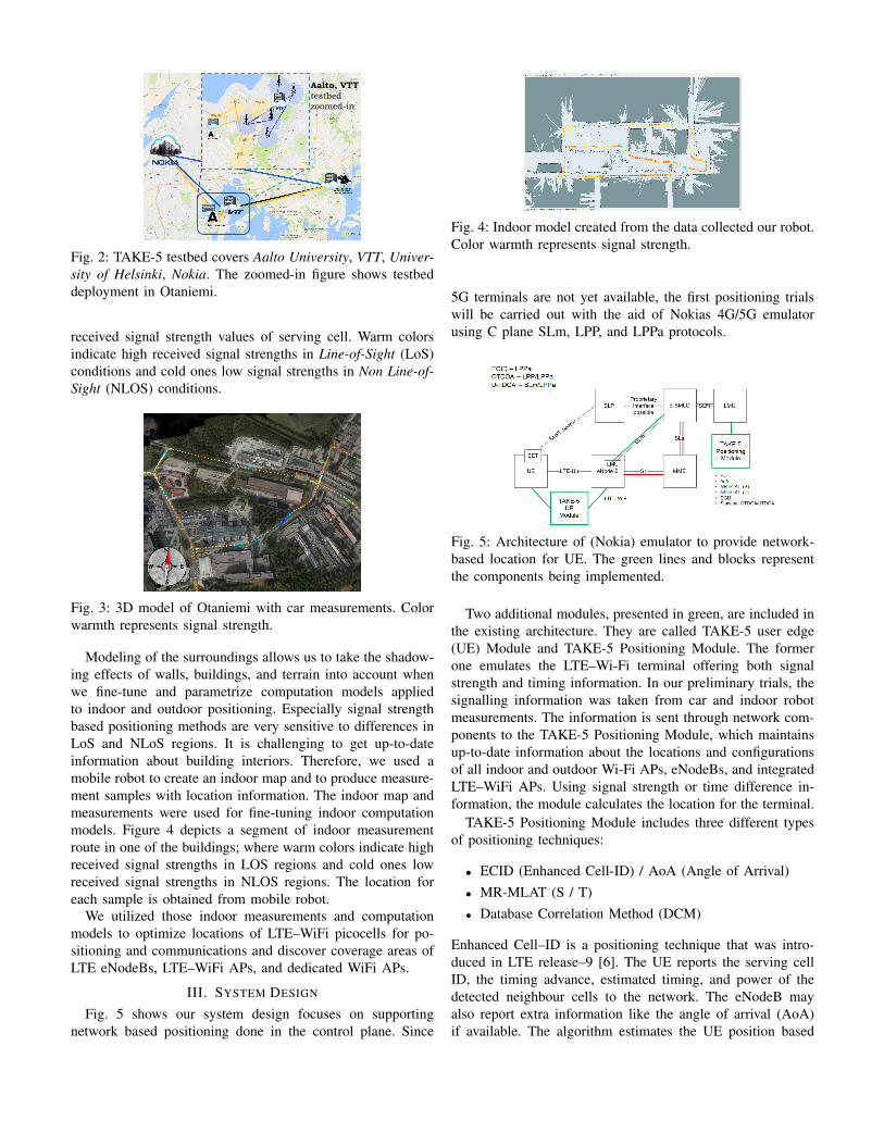
The integrate LTE and Wi-Fi test network covers roughly 4sq. km in area including interiors of three buildings whereNokia’s new LTE–Wi-Fi picocells have been installed ondifferent floors for positioning and latency reduction research.These floors have very different propagation characteristicsvarying from hall-like open spaces to maze-like spaces withnarrow corridors and thick walls (i.e. basements). Figure 2depicts the testbed environment.
To complement the testbed, we have also created a virtual3D model of Otaniemi and interior models of the buildingshaving LTE-Wi-Fi picocells, shown in Figure 3. The figurebelow shows a segment of an outdoor measurement routepresented on the top of 3D Otaniemi model. Figure 3 shows978-1-5090-6299-7/17/$31.00 © 2017 IEEE
����������������������������
Fig. 2: TAKE-5 testbed covers Aalto University, VTT, Univer-sity of Helsinki, Nokia. The zoomed-in figure shows testbeddeployment in Otaniemi.
received signal strength values of serving cell. Warm colorsindicate high received signal strengths in Line-of-Sight (LoS)conditions and cold ones low signal strengths in Non Line-of-Sight (NLOS) conditions.
Fig. 3: 3D model of Otaniemi with car measurements. Colorwarmth represents signal strength.
Modeling of the surroundings allows us to take the shadow-ing effects of walls, buildings, and terrain into account whenwe fine-tune and parametrize computation models appliedto indoor and outdoor positioning. Especially signal strengthbased positioning methods are very sensitive to differences inLoS and NLoS regions. It is challenging to get up-to-dateinformation about building interiors. Therefore, we used amobile robot to create an indoor map and to produce measure-ment samples with location information. The indoor map andmeasurements were used for fine-tuning indoor computationmodels. Figure 4 depicts a segment of indoor measurementroute in one of the buildings; where warm colors indicate highreceived signal strengths in LOS regions and cold ones lowreceived signal strengths in NLOS regions. The location foreach sample is obtained from mobile robot.
We utilized those indoor measurements and computationmodels to optimize locations of LTE–WiFi picocells for po-sitioning and communications and discover coverage areas ofLTE eNodeBs, LTE–WiFi APs, and dedicated WiFi APs.
III. SYSTEM DESIGN
Fig. 5 shows our system design focuses on supportingnetwork based positioning done in the control plane. Since
Fig. 4: Indoor model created from the data collected our robot.Color warmth represents signal strength.
5G terminals are not yet available, the first positioning trialswill be carried out with the aid of Nokias 4G/5G emulatorusing C plane SLm, LPP, and LPPa protocols.
Fig. 5: Architecture of (Nokia) emulator to provide network-based location for UE. The green lines and blocks representthe components being implemented.
Two additional modules, presented in green, are included inthe existing architecture. They are called TAKE-5 user edge(UE) Module and TAKE-5 Positioning Module. The formerone emulates the LTE–Wi-Fi terminal offering both signalstrength and timing information. In our preliminary trials, thesignalling information was taken from car and indoor robotmeasurements. The information is sent through network com-ponents to the TAKE-5 Positioning Module, which maintainsup-to-date information about the locations and configurationsof all indoor and outdoor Wi-Fi APs, eNodeBs, and integratedLTE–WiFi APs. Using signal strength or time difference in-formation, the module calculates the location for the terminal.
TAKE-5 Positioning Module includes three different typesof positioning techniques:
• ECID (Enhanced Cell-ID) / AoA (Angle of Arrival)• MR-MLAT (S / T)• Database Correlation Method (DCM)
Enhanced Cell–ID is a positioning technique that was intro-duced in LTE release–9 [6]. The UE reports the serving cellID, the timing advance, estimated timing, and power of thedetected neighbour cells to the network. The eNodeB mayalso report extra information like the angle of arrival (AoA)if available. The algorithm estimates the UE position based
on this information and its knowledge about eNodeB and APlocations.
Standardized UTDOA [2] and OTDOA [3], [7] use multi-lateration (MLAT) technique to determine the location of anUE based on the time it takes a signal to travel between an UEand multiple eNodeBs. Depending on the entity measuring thetime difference, the technique in LTE is called OTDOA (UEmeasuring) or UTDOA (network measuring). The OTDOAwas initially using Reference Signal Time Difference Mea-surement (RSTD). In Release 9, Positioning Reference Signals(PRS) were introduced to allow proper timing measurementsof a UE from eNodeBs [6].
In our work, we aim at performing MLAT calculationsusing both time and signal strength information from LTEeNodeBs and Wi-Fi APs. Therefore, we named this posi-tioning technique as MR-MLAT. MR refers to multi-radioaccess networks where the location estimate is computed fromdata obtained from licensed (LTE) and unlicensed (Wi-Fi)networks. The letter S indicates that the multi-lateration isdone using received signal strength and T with time differenceinformation.
The third experimented positioning algorithm is DatabaseCorrelation Method (DCM). It is a fingerprinting methodthat was introduced in 2001 [8]. This method was originallydeveloped to overcome multipath propagation and NLOS(Non-Line-of-Sight) problems. The DCM algorithm can beapplied to any wireless network. The key idea is to create adatabase of reference fingerprints from the area. The referencefingerprint is a recorded geo-referenced measurement sample.The reference fingerprint contains signal information from thecells that were detected during the measurement.
The positioning is conducted by comparing the signal prop-erties, e.g. signal strength or delay information, of the givenmeasurement sample to the samples stored in the databaseand returning the location of the best matching sample. In ourimplementation, the database comparison is done with the leastmean square (LMS) approach [9]. Also, other types of com-parison approaches e.g. learning based have been tested. Thedatabase can be built using single or multiple RAN sampleswith different network parameters e.g. signal strength, timinginformation, and QoS. The values stored in the fingerprintdatabase can be either measured or synthetically generated.Moreover, the database can be updated in real-time as long asthe new samples have location information attached to them.
The implemented DCM method has been enhanced withKalman, Extended Kalman and particle filters to reduce posi-tioning errors [9]. The Kalman filters are recursive solutionsof the discrete-data linear filtering problem. The filter usesthe information about its previous state during the estimationprocess of the current state. This information approximatesthe movement of a terminal and thus offers an estimate forthe heading and speed of an UE.
IV. IMPLEMENTATION
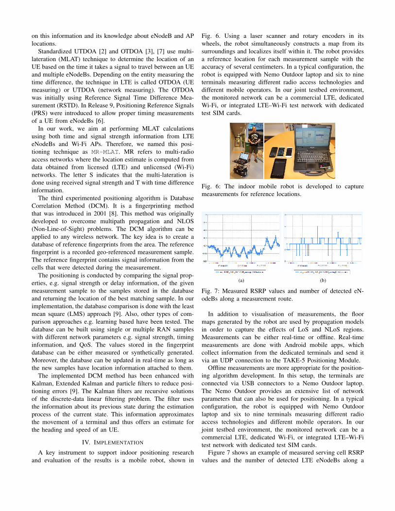
A key instrument to support indoor positioning researchand evaluation of the results is a mobile robot, shown in
Fig. 6. Using a laser scanner and rotary encoders in itswheels, the robot simultaneously constructs a map from itssurroundings and localizes itself within it. The robot providesa reference location for each measurement sample with theaccuracy of several centimeters. In a typical configuration, therobot is equipped with Nemo Outdoor laptop and six to nineterminals measuring different radio access technologies anddifferent mobile operators. In our joint testbed environment,the monitored network can be a commercial LTE, dedicatedWi-Fi, or integrated LTE–Wi-Fi test network with dedicatedtest SIM cards.
Fig. 6: The indoor mobile robot is developed to capturemeasurements for reference locations.
(a) (b)
Fig. 7: Measured RSRP values and number of detected eN-odeBs along a measurement route.
In addition to visualisation of measurements, the floormaps generated by the robot are used by propagation modelsin order to capture the effects of LoS and NLoS regions.Measurements can be either real-time or offline. Real-timemeasurements are done with Android mobile apps, whichcollect information from the dedicated terminals and send itvia an UDP connection to the TAKE-5 Positioning Module.
Offline measurements are more appropriate for the position-ing algorithm development. In this setup, the terminals areconnected via USB connectors to a Nemo Outdoor laptop.The Nemo Outdoor provides an extensive list of networkparameters that can also be used for positioning. In a typicalconfiguration, the robot is equipped with Nemo Outdoorlaptop and six to nine terminals measuring different radioaccess technologies and different mobile operators. In ourjoint testbed environment, the monitored network can be acommercial LTE, dedicated Wi-Fi, or integrated LTE–Wi-Fitest network with dedicated test SIM cards.
Figure 7 shows an example of measured serving cell RSRPvalues and the number of detected LTE eNodeBs along a
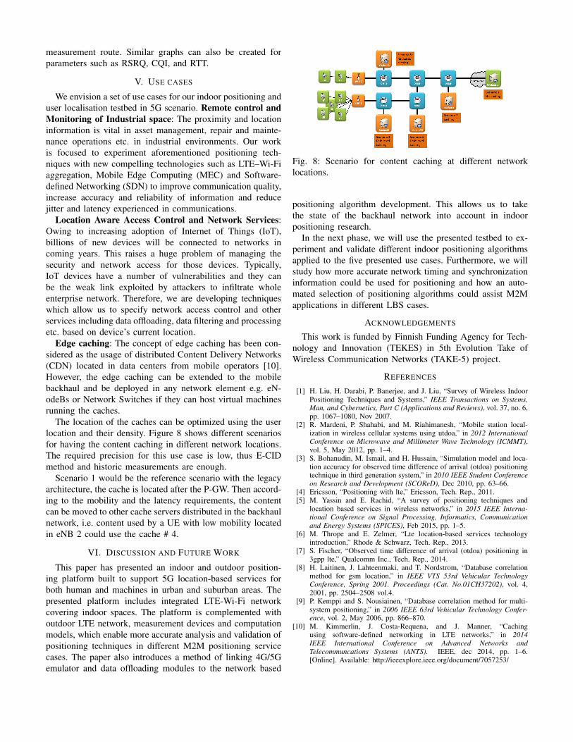
measurement route. Similar graphs can also be created forparameters such as RSRQ, CQI, and RTT.
V. USE CASES
We envision a set of use cases for our indoor positioning anduser localisation testbed in 5G scenario. Remote control andMonitoring of Industrial space: The proximity and locationinformation is vital in asset management, repair and mainte-nance operations etc. in industrial environments. Our workis focused to experiment aforementioned positioning tech-niques with new compelling technologies such as LTE–Wi-Fiaggregation, Mobile Edge Computing (MEC) and Software-defined Networking (SDN) to improve communication quality,increase accuracy and reliability of information and reducejitter and latency experienced in communications.
Location Aware Access Control and Network Services:Owing to increasing adoption of Internet of Things (IoT),billions of new devices will be connected to networks incoming years. This raises a huge problem of managing thesecurity and network access for those devices. Typically,IoT devices have a number of vulnerabilities and they canbe the weak link exploited by attackers to infiltrate wholeenterprise network. Therefore, we are developing techniqueswhich allow us to specify network access control and otherservices including data offloading, data filtering and processingetc. based on device’s current location.
Edge caching: The concept of edge caching has been con-sidered as the usage of distributed Content Delivery Networks(CDN) located in data centers from mobile operators [10].However, the edge caching can be extended to the mobilebackhaul and be deployed in any network element e.g. eN-odeBs or Network Switches if they can host virtual machinesrunning the caches.
The location of the caches can be optimized using the userlocation and their density. Figure 8 shows different scenariosfor having the content caching in different network locations.The required precision for this use case is low, thus E-CIDmethod and historic measurements are enough.
Scenario 1 would be the reference scenario with the legacyarchitecture, the cache is located after the P-GW. Then accord-ing to the mobility and the latency requirements, the contentcan be moved to other cache servers distributed in the backhaulnetwork, i.e. content used by a UE with low mobility locatedin eNB 2 could use the cache # 4.
VI. DISCUSSION AND FUTURE WORK
This paper has presented an indoor and outdoor position-ing platform built to support 5G location-based services forboth human and machines in urban and suburban areas. Thepresented platform includes integrated LTE-Wi-Fi networkcovering indoor spaces. The platform is complemented withoutdoor LTE network, measurement devices and computationmodels, which enable more accurate analysis and validation ofpositioning techniques in different M2M positioning servicecases. The paper also introduces a method of linking 4G/5Gemulator and data offloading modules to the network based
Fig. 8: Scenario for content caching at different networklocations.
positioning algorithm development. This allows us to takethe state of the backhaul network into account in indoorpositioning research.
In the next phase, we will use the presented testbed to ex-periment and validate different indoor positioning algorithmsapplied to the five presented use cases. Furthermore, we willstudy how more accurate network timing and synchronizationinformation could be used for positioning and how an auto-mated selection of positioning algorithms could assist M2Mapplications in different LBS cases.
ACKNOWLEDGEMENTS
This work is funded by Finnish Funding Agency for Tech-nology and Innovation (TEKES) in 5th Evolution Take ofWireless Communication Networks (TAKE-5) project.
REFERENCES
[1] H. Liu, H. Darabi, P. Banerjee, and J. Liu, “Survey of Wireless IndoorPositioning Techniques and Systems,” IEEE Transactions on Systems,Man, and Cybernetics, Part C (Applications and Reviews), vol. 37, no. 6,pp. 1067–1080, Nov 2007.
[2] R. Mardeni, P. Shahabi, and M. Riahimanesh, “Mobile station local-ization in wireless cellular systems using utdoa,” in 2012 InternationalConference on Microwave and Millimeter Wave Technology (ICMMT),vol. 5, May 2012, pp. 1–4.
[3] S. Bohanudin, M. Ismail, and H. Hussain, “Simulation model and loca-tion accuracy for observed time difference of arrival (otdoa) positioningtechnique in third generation system,” in 2010 IEEE Student Conferenceon Research and Development (SCOReD), Dec 2010, pp. 63–66.
[4] Ericsson, “Positioning with lte,” Ericsson, Tech. Rep., 2011.[5] M. Yassin and E. Rachid, “A survey of positioning techniques and
location based services in wireless networks,” in 2015 IEEE Interna-tional Conference on Signal Processing, Informatics, Communicationand Energy Systems (SPICES), Feb 2015, pp. 1–5.
[6] M. Thrope and E. Zelmer, “Lte location-based services technologyintroduction,” Rhode & Schwarz, Tech. Rep., 2013.
[7] S. Fischer, “Observed time difference of arrival (otdoa) positioning in3gpp lte,” Qualcomm Inc., Tech. Rep., 2014.
[8] H. Laitinen, J. Lahteenmaki, and T. Nordstrom, “Database correlationmethod for gsm location,” in IEEE VTS 53rd Vehicular TechnologyConference, Spring 2001. Proceedings (Cat. No.01CH37202), vol. 4,2001, pp. 2504–2508 vol.4.
[9] P. Kemppi and S. Nousiainen, “Database correlation method for multi-system positioning,” in 2006 IEEE 63rd Vehicular Technology Confer-ence, vol. 2, May 2006, pp. 866–870.
[10] M. Kimmerlin, J. Costa-Requena, and J. Manner, “Cachingusing software-defined networking in LTE networks,” in 2014IEEE International Conference on Advanced Networks andTelecommuncations Systems (ANTS). IEEE, dec 2014, pp. 1–6.[Online]. Available: http://ieeexplore.ieee.org/document/7057253/