Embed Size (px)
Citation preview
International Journal of Research in Social Sciences Vol. 7 Issue 5, May 2017, ISSN: 2249-2496 Impact Factor: 7.081
Journal Homepage: http://www.ijmra.us, Email: [email protected]
Double-Blind Peer Reviewed Refereed Open Access International Journal - Included in the International Serial
Directories Indexed & Listed at: Ulrich's Periodicals Directory ©, U.S.A., Open J-Gage as well as in Cabell’s
Directories of Publishing Opportunities, U.S.A
539 International Journal of Research in Social Sciences
http://www.ijmra.us, Email: [email protected]
A Survey on Routing Protocols of MANET in
Wireless Sensor Network
Vanitha*
Dr.R.Velayutham**
* Assistant Professor, Department of Computer Science and Engineering, Einstein College
of Engineering, Tirunelveli, India.
** HOD, Department of Computer Science and Engineering, Einstein College of
Engineering, Tirunelveli, India.
Abstract – A mobile ad hoc network (MANET) is a self configuring and decentralized network
in which moving nodes are mobiles. In MANET each node acts as a router and would
communicate with each other via wireless links. The network topology would change frequently
thereby forming dynamic topology. Minimization of energy consumption is requested in
MANET because all the nodes are operated by use of battery. The lifetime of Ad-hoc network
depends on the battery power. Wireless Sensor Networks (WSNs) is an integrated intelligent
information system with information acquisition, information transmission and information
processing. And it releases the information to the monitor that can be used in military and civil
fields widely. All the nodes in WSN have limited transmission range and low storage capacity.
Routing protocols have the responsibility of routing the packets in Wireless Sensor Network with
lower consumption of battery power. In this paper we study about the various routing protocols
and their behavior in MANET.
Keywords: WSN, MANET, Routing protocols, Proactive Routing Protocols, Reactive
Routing Protocols, Hybrid Routing Protocols, Hierarchical Routing Protocols.
ISSN: 2249-2496Impact Factor: 7.081
540 International Journal of Research in Social Sciences
http://www.ijmra.us, Email: [email protected]
I. Introduction
In Real world we use wireless sensor network widely. In the past decades, it has received more
attention from both education and industry all over the world [1]. A WSN typically consists of a
many number of low-cost, low-power, and multifunctional wireless sensor nodes, with sensing,
wireless communications and calculus capabilities [2]. Communication between the sensor nodes
are done over short distance via a wireless medium and collaborate to accomplish a collective
task, for example, habitat monitoring, military battlefield, and process control in industries [3].
The basic concept behind WSNs is that, while the potential of each individual sensor node is
limited, the total power of the entire network is sufficient for the required mission.
In many WSN applications, the deployment of sensor nodes is accomplished in an ad hoc fashion
without careful design and engineering. Once deployed, the sensor nodes must be able to
organize themselves into a wireless communication network autonomously. Sensor nodes are
work under the battery power so we cannot give any assurance about the lifetime of a sensor
node. It is very difficult and even impossible to modify or boost batteries for the sensor nodes in
the majority cases. Thus, the unique characteristics of a WSN contain many new challenges for
the applications and also the development.
A suitable network protocol is needed to implement various network control and management
functions such as node localization, synchronization, and network security because of all the
nodes in a sensor network are battery constraints. The already existing routing protocols are not
suitable to WSNs, because of the energy-constrained nature of wireless sensor networks [4].
For example, flooding is a technique in which a given node broadcasts data and control packets
to the remaining nodes in the network when it has received a packet from other sensor node. This
process repeats until the destination node is reached. This technique causes implosion and
overlap [5] because the single node can receive more duplicate packets because of broadcasting
the same packet again and again by multiple sensor nodes. So this is a blind technique. And also
consider two sensors nodes that have sensed the same region so the sensed data also same when
this sensed data broadcast by both the nodes then their neighbors will receive the duplicate
ISSN: 2249-2496Impact Factor: 7.081
541 International Journal of Research in Social Sciences
http://www.ijmra.us, Email: [email protected]
packets. To overcome the disadvantages of flooding, we use a technique called gossiping. [6].
In gossiping, a sensor node selects one neighbor node randomly from a set of neighbors and
sends a received packet whenever it receives a packet from other node. This process is repeated
until all sensors receive this packet. A given sensor would receive only one copy of a packet
being sent when we use gossiping. It increases network delay because all the nodes receive a
packet very lately when number of nodes in a network increases.
II. CHARACTERISTICS OF WIRELESS SENSOR NETWORK
Wireless sensor networks have the following unique characteristics and constraints [4]:
i. Sensor nodes are usually densely deployed and can be several orders of magnitude higher
than that in a MANET.
ii. With the use of battery power only sensor nodes activated and are deployed in a harsh
environment where it is very difficult to change or recharge the batteries.
iii. Sensors nodes are having highly limited energy, storage capabilities and computations.
iv. Sensor nodes are usually randomly deployed and autonomously configure themselves into a
communication network.
v. Since sensor nodes are prone to physical damages or failures due to its deployment in harsh
or hostile environment.
vi. In most sensor network application, sensor nodes are densely deployed in a region of interest
and collaborate to accomplish a common sensing task. Thus, the data sensed by multiple sensor
nodes typically have a certain level of correlation or redundancy.
vii. A sensor network is usually designed and deployed for a specific application. The design
requirements of a sensor network change with its application.
viii. In most sensor network applications, the data sensed by sensor nodes flow from multiple
source sensor nodes to a particular sink, exhibiting a many-to-one traffic pattern.
ix. Network topology changes frequently due to the node failures, damage, addition, energy
depletion, or channel fading.
ISSN: 2249-2496Impact Factor: 7.081
542 International Journal of Research in Social Sciences
http://www.ijmra.us, Email: [email protected]
III.ROUTING CHALLENGES IN WIRELESS SENSOR NETWORK
The design of routing protocols for WSNs is challenging because of several network constraints.
WSNs suffer from the limitations of several network resources, for example, energy, bandwidth,
central processing unit, and storage [7].
III.1. Energy constraint: The sensors are powered from batteries and it is not feasible to replace
or recharge the batteries. If battery failure occurs, then the network lifetime may be reduced. This
situation highly affects the performance of the system. Hence the design of the routing protocol
must take this issue into consideration to improve the performance of the system.
III.2. Scalability: WSN requires more number of sensor nodes to form large network. So, to
cover the large network, multi-hop communication is used between nodes. When the
communication goes to a longer distance, it may lead to minimize network lifetime. Hence
scalability is a significant factor that guarantees that the performance of the network should not
degrade as the network size increases.
III.3. Transmission media: Multi-hop communication can be carried out using wireless links.
This radio links are highly affected by interference, fading and noise etc. These wireless links can
be radio, infrared or optical media. These choices of transmission media to certain areas of WSN
makes more difficult.
III.4. Frequent occurrence of node failure: The communication between sensor nodes in WSN
may be affected by hardware failures, software faults and environmental changes. This leads to
frequent link failure on the established path. So the failures in communication link make some
sensor nodes to disconnect or partition from the network.
III.5. Hardware Constraint: In order to keep the sensor node very smaller size, the hardware
units used in sensor node has limited resources. For example, processor, memory units are
limited resources. Moreover, the network lifetime depends on the lifetime of the hardware
ISSN: 2249-2496Impact Factor: 7.081
543 International Journal of Research in Social Sciences
http://www.ijmra.us, Email: [email protected]
resources of sensor node.
III.6. Environment: Sensor nodes operate on different environment like under the ocean, forest
areas, under water, in vehicles etc and design accordingly. Therefore, the wireless sensor nodes
must support to work on different environment. Sometimes the sensor nodes deployed in a place
(e.g. Forest) where human involvement may not be always possible. In this situation, the sensor
nodes have to coordinate and form a network autonomously by adapting the environment.
III.7. Ad hoc deployment: Most sensor nodes are deployed in regions where human intervention
is less. For example, in forest areas, the sensor node has to be tossed from an aero plane. So, it is
the responsibility of the nodes to form a self-organizing network.
III.8. Topology maintenance: If sensor node fails, then the topology may be frequently changed
in WSNs. The deployment of additional nodes replaces the failure nodes which may lead to
frequent topology changes. The node connectivity has to support for new sensor nodes. So
topology management is a challenging issue in WSNs.
III.9. Fault tolerance: If the sensor node may drain out the energy or might be failed, then it is
important that the WSN has to manage the faults such as link failure, disconnection and network
partition and also tolerate it without affecting the performance of the entire network.
III.10. Sensor region: The sensing region of each sensor node may vary depends upon the
environment. The sensor nodes may be deployed on rocks, soil, under water, on grass and in
ground. Therefore, the sensing ability and sensing region of the sensor node will be changed.
Depending on the region, the radio communication also varied and thereby leads to problems in
WSNs.
IV. ROUTING PROTOCOLS IN WIRELESS SENSOR NETWORK
Routing in wireless sensor networks differs from conventional routing in fixed networks in
various ways. There is no infrastructure, wireless links are unreliable, sensor nodes may fail, and
ISSN: 2249-2496Impact Factor: 7.081
544 International Journal of Research in Social Sciences
http://www.ijmra.us, Email: [email protected]
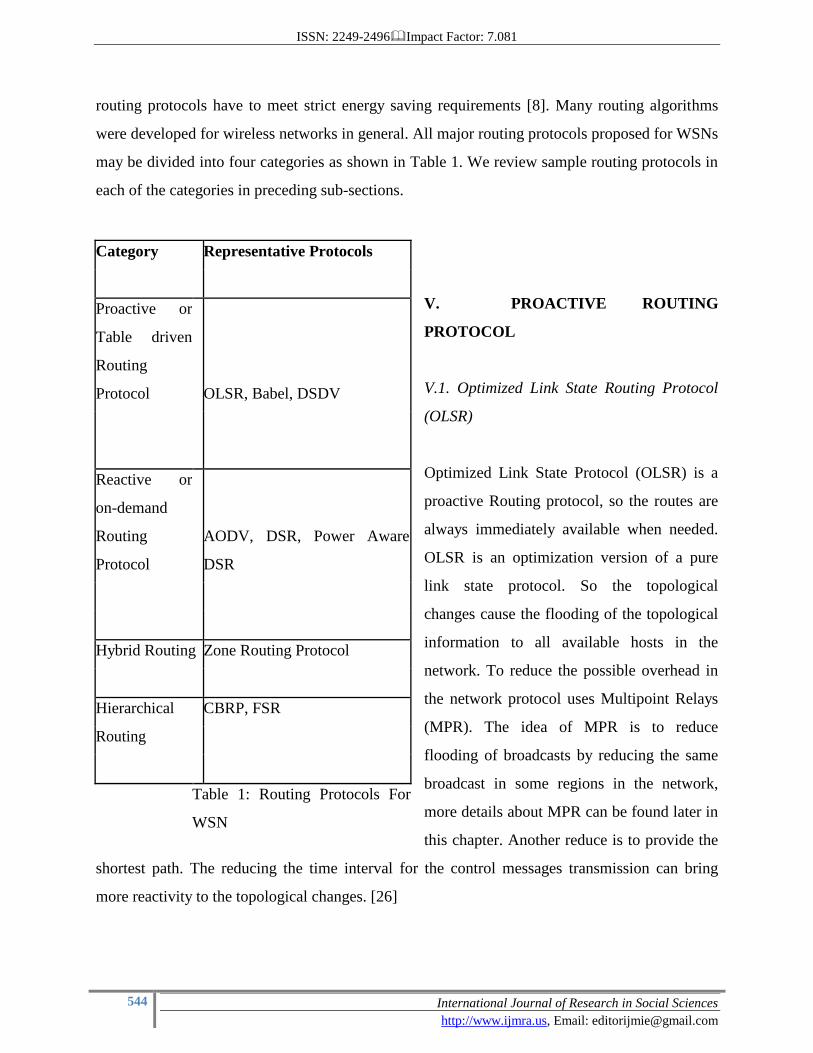
routing protocols have to meet strict energy saving requirements [8]. Many routing algorithms
were developed for wireless networks in general. All major routing protocols proposed for WSNs
may be divided into four categories as shown in Table 1. We review sample routing protocols in
each of the categories in preceding sub-sections.
V. PROACTIVE ROUTING
PROTOCOL
V.1. Optimized Link State Routing Protocol
(OLSR)
Optimized Link State Protocol (OLSR) is a
proactive Routing protocol, so the routes are
always immediately available when needed.
OLSR is an optimization version of a pure
link state protocol. So the topological
changes cause the flooding of the topological
information to all available hosts in the
network. To reduce the possible overhead in
the network protocol uses Multipoint Relays
(MPR). The idea of MPR is to reduce
flooding of broadcasts by reducing the same
broadcast in some regions in the network,
more details about MPR can be found later in
this chapter. Another reduce is to provide the
shortest path. The reducing the time interval for the control messages transmission can bring
more reactivity to the topological changes. [26]
Category Representative Protocols
Proactive or
Table driven
Routing
Protocol OLSR, Babel, DSDV
Reactive or
on-demand
Routing
Protocol
AODV, DSR, Power Aware
DSR
Hybrid Routing Zone Routing Protocol
Hierarchical CBRP, FSR
Routing
Table 1: Routing Protocols For
WSN
ISSN: 2249-2496Impact Factor: 7.081
545 International Journal of Research in Social Sciences
http://www.ijmra.us, Email: [email protected]
OLSR uses two kinds of the control messages: Hello and Topology Control (TC). Hello
messages are used for finding the information about the link status and the host’s neighbors.
With the Hello message the Multipoint Relay (MPR) Selector set is constructed which describes
which neighbors has chosen this host to act as MPR and from this information the host can
calculate its own set of the MPRs. the Hello messages are sent only one hop away but the TC
messages are broadcasted throughout the entire network. TC messages are used for broadcasting
information about own advertised neighbors which includes at least the MPR Selector list. The
TC messages are broadcasted periodically and only the MPR hosts can forward the TC messages.
[27]
There is also Multiple Interface Declaration (MID) messages which are used for informing other
host that the announcing host can have multiple OLSR interface addresses. The MID message is
broadcasted throughout the entire network only by giving the possibility for routing to the
external addresses. The HNA message provides information about the network- and the net mask
addresses, so that OLSR host can consider that the announcing host can act as a gateway to the
announcing set of addresses. The HNA is considered as a generalized version of the TC message
with only difference that the TC message can inform about route cancelling while HNA message
information is removed only after expiration time.
V.2. Babel Routing Protocol
Babel is a loop-avoiding distance-vector routing protocol that is designed to be robust and
efficient both in networks using prefix-based routing and in networks using flat routing ("mesh
networks"), and both in relatively stable wired networks and in highly dynamic wireless
networks. [9]
Babel was originally designed for wireless ad-hoc networks. Because of that, Babel is extremely
robust in the presence of mobility: only under very exceptional situations circumstances will
Babel cause a transient routing loop. The Babel protocol variant is also able to take radio
frequency into account in order to avoid interference. [10]
ISSN: 2249-2496Impact Factor: 7.081
546 International Journal of Research in Social Sciences
http://www.ijmra.us, Email: [email protected]
Unlike most routing protocols, which route either IPv4 or IPv6 but not both at the same time,
Babel is a hybrid routing protocol, in the sense that a single update packet can carry routes for
multiple network-layer protocols (both IPv6 and IPv4 routes). This makes Babel particularly
efficient and simple to manage on dual (IPv6 and IPv4) networks.
Babel has two disadvantages that make it unsuitable for use in some environments:
1) Babel relies on periodic routing table updates rather than using a reliable transport (hence, in
large, stable networks it generates more traffic than protocols that only send updates when the
network topology changes);
2) Babel does impose a hold time when a prefix is retracted. This makes Babel unsuitable for
use in mobile networks that implement automatic prefix aggregation. [9]
V.3. Destination-Sequenced Distance Vector (DSDV)
Destination sequenced distance vector routing (DSDV) protocol is one of the popular proactive
routing procols of ad hoc network. In DSDV, each node keeps record of route information in the
form of routing table. Each table contains the information’s such as ID of destination node,
Details of next hop, Metric, Sequence number, Time-to-live parameter. Using the newly added
sequence number, the mobile nodes can distinguish stale route information from the new and
thus prevent the formation of routing loops.
Packet Routing and Routing Table Management [11]
In DSDV, each mobile node of an ad hoc network maintains a routing table, which lists all
available destinations, the metric and next hop to each destination and a sequence number
generated by the destination node. The nodes in an ad hoc network transmit the packet based on
the information available in the routing table of each node. By advertising each node themselves
they updates the routing table information’s periodically or when significant new information is
available to maintain the consistency of the routing table with the dynamically changing topology
of the ad hoc network.
ISSN: 2249-2496Impact Factor: 7.081
547 International Journal of Research in Social Sciences
http://www.ijmra.us, Email: [email protected]
The entire node advertises the change of routing table information by broadcasting or
multicasting a routing table update packet when a network topology changes are detected. The
metric field of update packet starts with one to direct connected nodes. This indicates that each
receiving neighbor is one metric (hop) away from the node. It is different from that of the
conventional routing algorithms. After receiving the update packet, the neighbors update their
routing table with incrementing the metric by one and retransmit the update packet to the
corresponding neighbors of each of them. This process is repeated until all the nodes in an ad hoc
network received a copy of update packet with a corresponding metric. The update data is also
kept for a while to wait for the arrival of the best route for each particular destination node in
each node before updating its routing table and retransmitting the update packet. During the
waiting period a node can receive multiple update packet for a same destination, the routes with
more recent sequence numbers are always preferred as the basis for packet forwarding decisions,
but the routing information is not necessarily advertised immediately, if only the sequence
numbers have been changed. The update packet with the smallest metric will be used and the
existing route will be discarded or stored as a less preferable route when the update packets have
the same sequence number with the same node. In this case, the update packet will be propagated
with the sequence number to all mobile nodes in the ad hoc network. The advertisements of
routes that are about to change may be delayed until the best routes have been found. Delaying
the advertisement of possibly unstable route can damp the fluctuations of the routing table and
reduce the number of rebroadcasts of possible route entries that arrive with the same sequence
number.
The routing table elements of each mobile node change dynamically to keep consistency with
dynamically changing topology of an ad hoc network. To reach this consistency, the routing
information advertisement must be frequent or quick enough to ensure that each mobile node can
almost always locate all the other mobile nodes in the dynamic ad hoc network. Each node has to
relay data packet to other nodes depending upon the information available in updated routing
table upon request in the dynamically created ad hoc network.
ISSN: 2249-2496Impact Factor: 7.081
548 International Journal of Research in Social Sciences
http://www.ijmra.us, Email: [email protected]
815
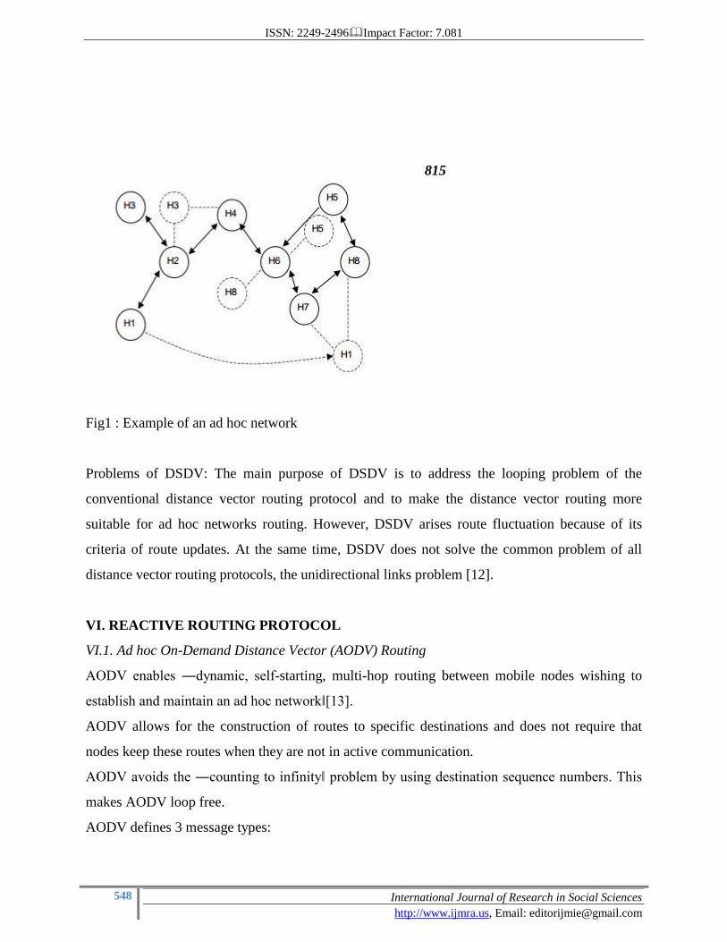
Fig1 : Example of an ad hoc network
Problems of DSDV: The main purpose of DSDV is to address the looping problem of the
conventional distance vector routing protocol and to make the distance vector routing more
suitable for ad hoc networks routing. However, DSDV arises route fluctuation because of its
criteria of route updates. At the same time, DSDV does not solve the common problem of all
distance vector routing protocols, the unidirectional links problem [12].
VI. REACTIVE ROUTING PROTOCOL
VI.1. Ad hoc On-Demand Distance Vector (AODV) Routing
AODV enables ―dynamic, self-starting, multi-hop routing between mobile nodes wishing to
establish and maintain an ad hoc network‖[13].
AODV allows for the construction of routes to specific destinations and does not require that
nodes keep these routes when they are not in active communication.
AODV avoids the ―counting to infinity‖ problem by using destination sequence numbers. This
makes AODV loop free.
AODV defines 3 message types:
ISSN: 2249-2496Impact Factor: 7.081
549 International Journal of Research in Social Sciences
http://www.ijmra.us, Email: [email protected]
– Route Requests (RREQs)
– Route Replies (RREPs)
– Route Errors (RERRs)
• RREQ messages are used to initiate the route finding process.
• RREP messages are used to finalize the routes.
• RERR messages are used to notify the network of a link breakage in an active route.
The Path Discovery process is initiated whenever a source node needs to communicate with
another node for which it has no routing information in its table Every node maintains two
separate counters. a node sequence number and a broadcast id The source node initiates path
discovery by broadcasting a route request (RREQ) packet to its neighbors. The pair <source addr,
broadcast id> uniquely identifies a RREQ broadcast id is incremented whenever the source issues
a new RREQ Each neighbor either satisfies the RREQ by sending a route reply (RREP) back to
the source. or rebroadcasts the RREQ to its own neighbors after increasing the hop cnt Notice
that a node may receive multiple copies of the same route broadcast packet from various
neighbors When an intermediate node receives a RREQ if it has already received a RREQ with
the same broadcast id and source address it drops the redundant RREQ and does not rebroadcast
it If a node cannot satisfy the RREQ it keeps track of the following information in order to
implement the reverse path setup as well as the forward path setup that will accompany the
transmission of the eventual (RREP).
There are two sequence numbers (in addition to the broadcast id) included in a RREQ: the source
sequence number and the last destination sequence number known to the source The source
sequence number is used to maintain freshness information about the reverse route to the source
and the destination sequence number specifies how fresh a route to the destination must be
before it can be accepted by the source.
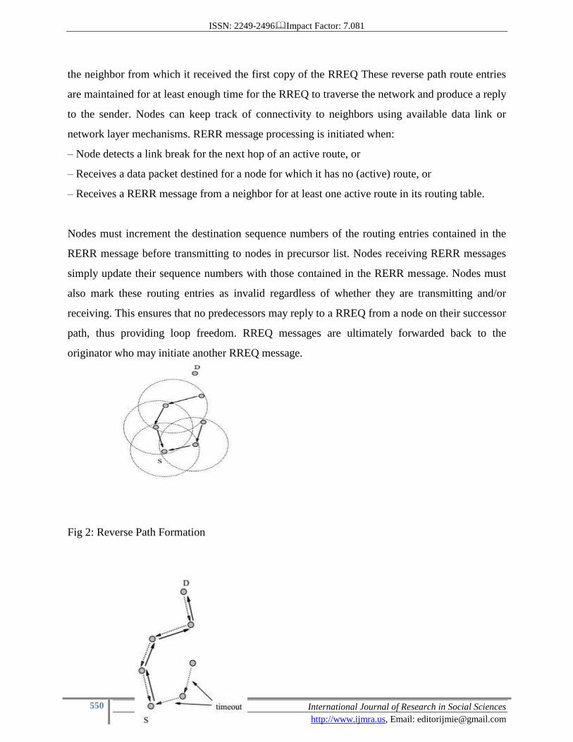
As the RREQ travels from a source to various destinations it automatically sets up the reverse
path from all nodes back to the source [14]. To set up a reverse path a node records the address of
ISSN: 2249-2496Impact Factor: 7.081
550 International Journal of Research in Social Sciences
http://www.ijmra.us, Email: [email protected]
the neighbor from which it received the first copy of the RREQ These reverse path route entries
are maintained for at least enough time for the RREQ to traverse the network and produce a reply
to the sender. Nodes can keep track of connectivity to neighbors using available data link or
network layer mechanisms. RERR message processing is initiated when:
– Node detects a link break for the next hop of an active route, or
– Receives a data packet destined for a node for which it has no (active) route, or
– Receives a RERR message from a neighbor for at least one active route in its routing table.
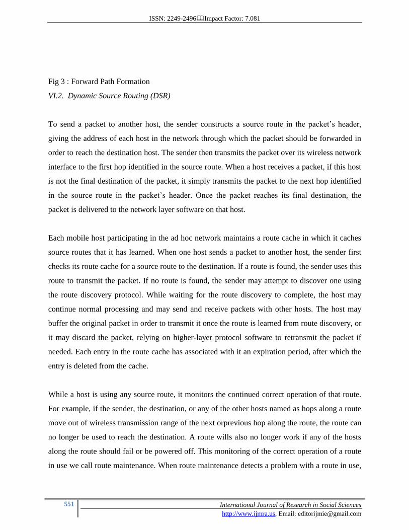
Nodes must increment the destination sequence numbers of the routing entries contained in the
RERR message before transmitting to nodes in precursor list. Nodes receiving RERR messages
simply update their sequence numbers with those contained in the RERR message. Nodes must
also mark these routing entries as invalid regardless of whether they are transmitting and/or
receiving. This ensures that no predecessors may reply to a RREQ from a node on their successor
path, thus providing loop freedom. RREQ messages are ultimately forwarded back to the
originator who may initiate another RREQ message.
Fig 2: Reverse Path Formation
ISSN: 2249-2496Impact Factor: 7.081
551 International Journal of Research in Social Sciences
http://www.ijmra.us, Email: [email protected]
Fig 3 : Forward Path Formation
VI.2. Dynamic Source Routing (DSR)
To send a packet to another host, the sender constructs a source route in the packet’s header,
giving the address of each host in the network through which the packet should be forwarded in
order to reach the destination host. The sender then transmits the packet over its wireless network
interface to the first hop identified in the source route. When a host receives a packet, if this host
is not the final destination of the packet, it simply transmits the packet to the next hop identified
in the source route in the packet’s header. Once the packet reaches its final destination, the
packet is delivered to the network layer software on that host.
Each mobile host participating in the ad hoc network maintains a route cache in which it caches
source routes that it has learned. When one host sends a packet to another host, the sender first
checks its route cache for a source route to the destination. If a route is found, the sender uses this
route to transmit the packet. If no route is found, the sender may attempt to discover one using
the route discovery protocol. While waiting for the route discovery to complete, the host may
continue normal processing and may send and receive packets with other hosts. The host may
buffer the original packet in order to transmit it once the route is learned from route discovery, or
it may discard the packet, relying on higher-layer protocol software to retransmit the packet if
needed. Each entry in the route cache has associated with it an expiration period, after which the
entry is deleted from the cache.
While a host is using any source route, it monitors the continued correct operation of that route.
For example, if the sender, the destination, or any of the other hosts named as hops along a route
move out of wireless transmission range of the next orprevious hop along the route, the route can
no longer be used to reach the destination. A route wills also no longer work if any of the hosts
along the route should fail or be powered off. This monitoring of the correct operation of a route
in use we call route maintenance. When route maintenance detects a problem with a route in use,
ISSN: 2249-2496Impact Factor: 7.081
552 International Journal of Research in Social Sciences
http://www.ijmra.us, Email: [email protected]
route discovery may be used again to discover a new, correct route to the destination [15].
In DSR, when a mobile (source) needs a route to another mobile (destination), it initiates a route
discovery process which is based on flooding. The source originates a RREQ packet that is
flooded over the network. The RREQ packet contains a list of hops which is collected by the
route request packet as it is propagated through the network. Once the RREQ reaches either the
destination or a node that knows a route to the destination, it responds with a RREP along the
reverse of the route collected by the RREQ [15]. This means that the source may receive several
RREP messages corresponding, in general, to different routes to the destination. DSR selects one
of these routes (for example the shortest), and it maintains the other routes in a cache. The routes
in the cache can be used as substitutes to speed up the route discovery if the selected route gets
disconnected. To avoid that RREQ packets travel forever in the network, nodes, that have already
processed a RREQ, discard any further RREQ bearing the same identifier.
The main difference between DSR and AODV is in the way they keep the information about the
routes: in DSR it is stored in the source while in AODV it is stored in the intermediate nodes.
However, the route discovery phase of both is based on flooding. This means that all nodes in the
network must participate in every discovery process, regardless of their potential in actually
contributing to set up the route or not, thus increasing the network load [16].
VII. HYBRID ROUTING PROTOCOL
VII.1. Zone Routing Protocol (ZRP)
As seen, proactive routing uses excess bandwidth to maintain routing information, while reactive
routing involves long route request delays. Reactive routing also inefficiently floods the entire
network for route determination. The Zone Routing Protocol (ZRP) aims to address the problems
by combining the best properties of both approaches. ZRP can be classed as a hybrid
reactive/proactive routing protocol. [17]
In an ad-hoc network, it can be assumed that the largest part of the traffic is directed to nearby
nodes. Therefore, ZRP reduces the proactive scope to a zone centered on each node. In a limited
zone, the maintenance of routing information is easier. Further, the amount of routing
ISSN: 2249-2496Impact Factor: 7.081
553 International Journal of Research in Social Sciences
http://www.ijmra.us, Email: [email protected]
information that is never used is minimized. Still, nodes farther away can be reached with
reactive routing. Since all nodes proactively store local routing information, route requests can be
more efficiently performed without querying all the network nodes. [17]
Despite the use of zones, ZRP has a flat view over the network. In this way, the organizational
overhead related to hierarchical protocols can be avoided. Hierarchical routing protocols depend
on the strategic assignment of gateways or landmarks, so that every node can access all levels,
especially the top level. Nodes belonging to different subnets must send their communication to a
subnet that is common to both nodes. This may congest parts of the network. ZRP can be
categorized as a flat protocol because the zones overlap. Hence, optimal routes can be detected
and network congestion can be reduced. [18]
Further, the behavior of ZRP is adaptive. The behavior depends on the current configuration of
the network and the behavior of the users. [17]
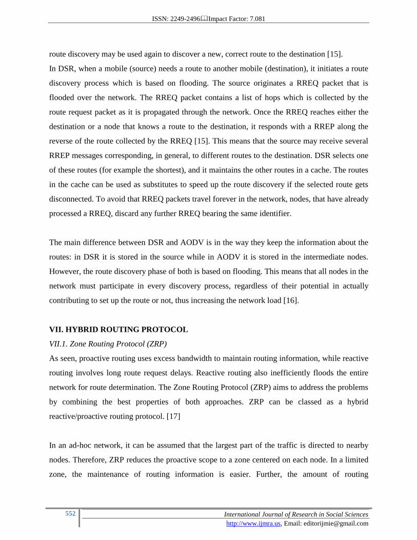
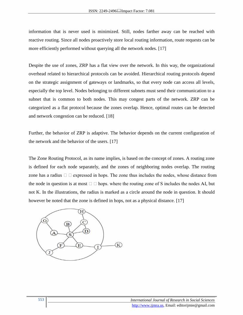
The Zone Routing Protocol, as its name implies, is based on the concept of zones. A routing zone
is defined for each node separately, and the zones of neighboring nodes overlap. The routing
zone has a radius expressed in hops. The zone thus includes the nodes, whose distance from
the node in question is at most hops. where the routing zone of S includes the nodes A–I, but
not K. In the illustrations, the radius is marked as a circle around the node in question. It should
however be noted that the zone is defined in hops, not as a physical distance. [17]
ISSN: 2249-2496Impact Factor: 7.081
554 International Journal of Research in Social Sciences
http://www.ijmra.us, Email: [email protected]
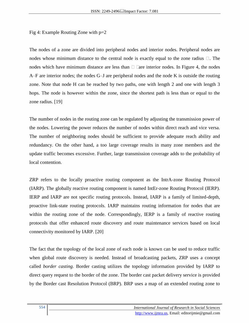
Fig 4: Example Routing Zone with p=2
The nodes of a zone are divided into peripheral nodes and interior nodes. Peripheral nodes are
nodes whose minimum distance to the central node is exactly equal to the zone radius . The
nodes which have minimum distance are less than are interior nodes. In Figure 4, the nodes
A–F are interior nodes; the nodes G–J are peripheral nodes and the node K is outside the routing
zone. Note that node H can be reached by two paths, one with length 2 and one with length 3
hops. The node is however within the zone, since the shortest path is less than or equal to the
zone radius. [19]
The number of nodes in the routing zone can be regulated by adjusting the transmission power of
the nodes. Lowering the power reduces the number of nodes within direct reach and vice versa.
The number of neighboring nodes should be sufficient to provide adequate reach ability and
redundancy. On the other hand, a too large coverage results in many zone members and the
update traffic becomes excessive. Further, large transmission coverage adds to the probability of
local contention.
ZRP refers to the locally proactive routing component as the IntrA-zone Routing Protocol
(IARP). The globally reactive routing component is named IntEr-zone Routing Protocol (IERP).
IERP and IARP are not specific routing protocols. Instead, IARP is a family of limited-depth,
proactive link-state routing protocols. IARP maintains routing information for nodes that are
within the routing zone of the node. Correspondingly, IERP is a family of reactive routing
protocols that offer enhanced route discovery and route maintenance services based on local
connectivity monitored by IARP. [20]
The fact that the topology of the local zone of each node is known can be used to reduce traffic
when global route discovery is needed. Instead of broadcasting packets, ZRP uses a concept
called border casting. Border casting utilizes the topology information provided by IARP to
direct query request to the border of the zone. The border cast packet delivery service is provided
by the Border cast Resolution Protocol (BRP). BRP uses a map of an extended routing zone to
ISSN: 2249-2496Impact Factor: 7.081
555 International Journal of Research in Social Sciences
http://www.ijmra.us, Email: [email protected]
construct border cast trees for the query packets. Alternatively, it uses source routing based on
the normal routing zone. By employing query control mechanisms, route requests can be directed
away from areas of the network that already have been covered. [21]
In order to detect new neighbor nodes and link failures, the ZRP relies on a Neighbor Discovery
Protocol (NDP) provided by the Media Access Control (MAC) layer. NDP transmits ―HELLO
beacons at regular intervals. Upon receiving a beacon, the neighbor table is updated. Neighbors,
for which no beacon has been received within a specified time, are removed from the table. If the
MAC layer does not include a NDP, the functionality must be provided by IARP. [22]
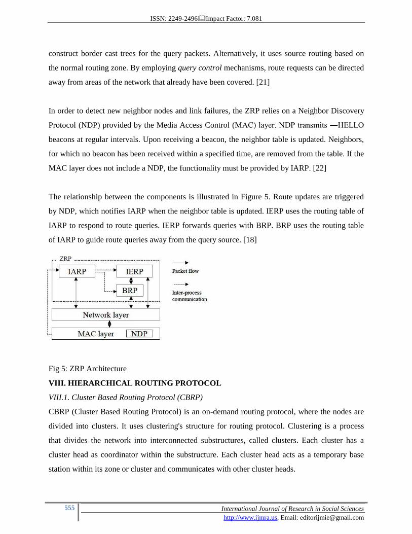
The relationship between the components is illustrated in Figure 5. Route updates are triggered
by NDP, which notifies IARP when the neighbor table is updated. IERP uses the routing table of
IARP to respond to route queries. IERP forwards queries with BRP. BRP uses the routing table
of IARP to guide route queries away from the query source. [18]
Fig 5: ZRP Architecture
VIII. HIERARCHICAL ROUTING PROTOCOL
VIII.1. Cluster Based Routing Protocol (CBRP)
CBRP (Cluster Based Routing Protocol) is an on-demand routing protocol, where the nodes are
divided into clusters. It uses clustering's structure for routing protocol. Clustering is a process
that divides the network into interconnected substructures, called clusters. Each cluster has a
cluster head as coordinator within the substructure. Each cluster head acts as a temporary base
station within its zone or cluster and communicates with other cluster heads.
ISSN: 2249-2496Impact Factor: 7.081
556 International Journal of Research in Social Sciences
http://www.ijmra.us, Email: [email protected]
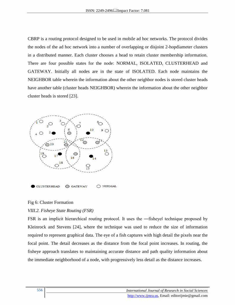
CBRP is a routing protocol designed to be used in mobile ad hoc networks. The protocol divides
the nodes of the ad hoc network into a number of overlapping or disjoint 2-hopdiameter clusters
in a distributed manner. Each cluster chooses a head to retain cluster membership information.
There are four possible states for the node: NORMAL, ISOLATED, CLUSTERHEAD and
GATEWAY. Initially all nodes are in the state of ISOLATED. Each node maintains the
NEIGHBOR table wherein the information about the other neighbor nodes is stored cluster heads
have another table (cluster heads NEIGHBOR) wherein the information about the other neighbor
cluster heads is stored [23].
Fig 6: Cluster Formation
VIII.2. Fisheye State Routing (FSR)
FSR is an implicit hierarchical routing protocol. It uses the ―fisheye‖ technique proposed by
Kleinrock and Stevens [24], where the technique was used to reduce the size of information
required to represent graphical data. The eye of a fish captures with high detail the pixels near the
focal point. The detail decreases as the distance from the focal point increases. In routing, the
fisheye approach translates to maintaining accurate distance and path quality information about
the immediate neighborhood of a node, with progressively less detail as the distance increases.
ISSN: 2249-2496Impact Factor: 7.081
557 International Journal of Research in Social Sciences
http://www.ijmra.us, Email: [email protected]
FSR is functionally similar to LS Routing in that it maintains a topology map at each node. The
key difference is the way in which routing information is disseminated. In LS, link state packets
are generated and flooded into the network whenever a node detects a topology change. In FSR,
link state packets are not flooded. Instead, nodes maintain a link state table based on the up-to-
date information received from neighboring nodes, and periodically exchange it with their local
neighbors only (no flooding). Through this exchange process, the table entries with larger
sequence numbers replace the ones with smaller sequence numbers. The FSR periodic table
exchange resembles the vector exchange in Distributed Bellman-Ford (DBF) (or more precisely,
DSDV [25]) where the distances are updated according to the time stamp or sequence number
assigned by the node originating the update. However, in FSR link states rather than distance
vectors are propagated. Moreover, like in LS, a full topology map is kept at each node and
shortest paths are computed using this map.
In a wireless environment, a radio link between mobile nodes may experience frequent
disconnects and reconnects. The LS protocol releases a link state update for each such change,
which floods the network and causes excessive overhead. FSR avoids this problem by using
periodic, instead of event driven, exchange of the topology map, greatly reducing the control
message overhead. When network size grows large, the update message could consume
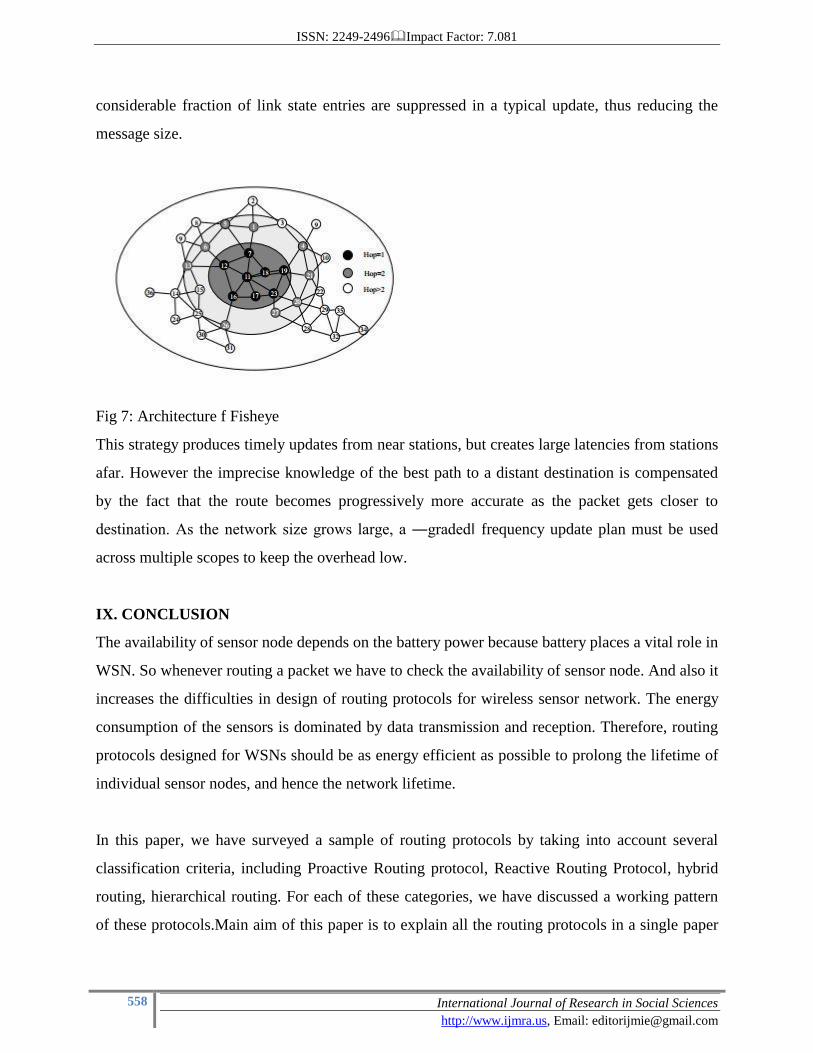
considerable amount of bandwidth, which depends on the update period. In order to reduce the
size of update messages without seriously affecting routing accuracy, FSR uses the fisheye
technique. The circles with different shades of grey define the fisheye scopes with respect to the
center node (node 11). The scope is defined as the set of nodes that can be reached within a given
number of hops. In our case, three scopes are shown for 1, 2 and 2 hops respectively. Nodes are
color coded as black, grey and white accordingly. The number of levels and the radius of each
scope will depend on the size of the network.
The reduction of routing update overhead is obtained by using different exchange periods for
different entries in routing table. More precisely, entries corresponding to nodes within the
smaller scope are propagated to the neighbors with the highest frequency. Entries in bold are
exchanged most frequently. The rest of the entries are sent out at a lower frequency. As a result, a
ISSN: 2249-2496Impact Factor: 7.081
558 International Journal of Research in Social Sciences
http://www.ijmra.us, Email: [email protected]
considerable fraction of link state entries are suppressed in a typical update, thus reducing the
message size.
Fig 7: Architecture f Fisheye
This strategy produces timely updates from near stations, but creates large latencies from stations
afar. However the imprecise knowledge of the best path to a distant destination is compensated
by the fact that the route becomes progressively more accurate as the packet gets closer to
destination. As the network size grows large, a ―graded‖ frequency update plan must be used
across multiple scopes to keep the overhead low.
IX. CONCLUSION
The availability of sensor node depends on the battery power because battery places a vital role in
WSN. So whenever routing a packet we have to check the availability of sensor node. And also it
increases the difficulties in design of routing protocols for wireless sensor network. The energy
consumption of the sensors is dominated by data transmission and reception. Therefore, routing
protocols designed for WSNs should be as energy efficient as possible to prolong the lifetime of
individual sensor nodes, and hence the network lifetime.
In this paper, we have surveyed a sample of routing protocols by taking into account several
classification criteria, including Proactive Routing protocol, Reactive Routing Protocol, hybrid
routing, hierarchical routing. For each of these categories, we have discussed a working pattern
of these protocols.Main aim of this paper is to explain all the routing protocols in a single paper
ISSN: 2249-2496Impact Factor: 7.081
559 International Journal of Research in Social Sciences
http://www.ijmra.us, Email: [email protected]
for an easy understanding of all the MANET routing protocols.
References
[1] ―21 ideas for the 21st century‖, Business Week, Aug. 30 1999, pp. 78-167.
[2] S.K. Singh, M.P. Singh, and D.K. Singh, ―A survey of Energy-Efficient Hierarchical
Cluster-based Routing in Wireless Sensor Networks‖, International Journal of Advanced
Networking and Application (IJANA), Sept.–Oct. 2010, vol. 02, issue 02, pp. 570–580.
[3] S .K.Singh, M.P.Singh, and D.K .Singh , " Energy – efficient Homogeneous Clustering
Algorithm for Wireless Sensor Network", International Journal of Wireless & Mobile Networks
(IJWMN), Aug. 2010, vol. 2, no. 3, pp. 49-61.
[4] Jun Zheng and Abbas Jamalipour, ―Wireless Sensor Networks: A Networking
Perspective‖, a book
[5] Luis Javier García Villalba, Ana Lucila Sandoval Orozco, AliciaTriviño Cabrera , and
Cláudia Jacy Barenco Abbas , ― Routing Protocol in Wireless Sensor Networks‖, Sensors 2009,
vol. 9, pp. 8399- 8421.
[6] E . Zanaj , M . Baldi , and F . Chiaraluce , ― Efficiency of the Gossip Algorithm for
Wireless Sensor Networks, In Proceedings of the 15th
International Conference on Software,
Telecommunications
[7]Jamal Al – Karaki , and Ahmed E. Kamal, ―Routing Techniques in Wireless Sensor
Networks : A Survey ― , IEEE Communications Magazine, vol 11, no. 6, Dec. 2004, pp. 6-28.
[8] S . Misra et al. ( eds .), Guide to Wireless Sensor Networks, Computer Communications and
Networks , DOI: 10.1007/978-1-84882-218-4 4, Springer-Verlag London Limited 2009.
[9] 1 J . Chroboczek , The Babel Routing Protocol, RFC 6126, ISSN 2070-1721, April 2011.
[10] 2J . Chroboczek ,Babel – a loop-avoiding distance- vector routing protocol,
http://www.pps.univ-parisdiderot.fr/jch/software/babel
[11] Perkins Charles E. Bhagwat Pravin: Highly Dynamic Destination Sequenced Distance –
Vector Routing(DSDV) for Mobile Computers, London England UK, SIGCOMM 94-8/94.
[12] Guoyou He , ― Destination – Sequenced Distance Vector ( DSDV ) Protocol‖ ,
Networking Laboratory , Helsinki University of Technology , [email protected]
[13] Perkins, et. al. ―Ad hoc On-Demand Distance Vector (AODV) Routing‖, RFC 3561, July
ISSN: 2249-2496Impact Factor: 7.081
560 International Journal of Research in Social Sciences
http://www.ijmra.us, Email: [email protected]
2003
[14] M . S . Corson and A. Ephremides. A Distributed Routing Algorithm for Mobile Wireless
Networks. ACM J Wireless Networks, 1(1), jan.1995.
[15] David B. Johnson, David A. Maltz ―Dynamic Source Routing in Ad Hoc Wireless
Networks, Mobile Computing, Thomasz Imielinski and Hank Korth (Editors) , ‖ Vol . 353,
Chapter 5, pp. 153- 181, Kluwer Academic Publishers, 1996.
[16] Akshai Aggarwal , Savita Gandhi, Nirbhay Chaubey , ―performance analysis of aodv,
dsdv and dsr in manets‖ ,International Journal of Distributed and Parallel Systems (IJDPS)
Vol.2, No.6, November 2011
[17] Pearlman , Marc R ., Haas , Zygmunt J.: Determining the Optimal Configuration for the
Zone Routing Protocol, August 1999, IEEE Journal on Selected Areas in Communications, Vol.
17, No. 8
[18] Haas, Zygmunt J., Pearlman, Marc R.: The Performance of Query Control Schemes for the
Zone Routing Protocol, August 2001, IEEE/ACM Transactions on Networking, Vol. 9, No. 4
[19] Haas, Zygmunt J., Pearlman, Marc R., Samar, P.: Intrazone Routing Protocol (IARP), June
2001, IETF Internet Draft, draft-ietf-manet-iarp-01.txt
[20] Haas, Zygmunt J., Pearlman, Marc R., Samar, P.: Interzone Routing Protocol (IERP), June
2001, IETF Internet Draft, draft-ietf-manet-ierp-01.txt
[21] Haas, Zygmunt J., Pearlman, Marc R., Samar, P. : The Bordercast Resolution Protocol
(BRP) for Ad Hoc Networks, June 2001, IETF Internet Draft, draft-ietf-manet-brp-01.txt
[22] Haas , Zygmunt J., Pearlman, Marc R.: Providing Ad-hoc Connectivity With Reconfigurable
Wireless Networks , Ihaca , New York, http://www.ee.cornell.edu/~haas/wnl.html
[23]M . Jiang , J . Li , and Y . C . Tay. “Cluster Based Routing Protocol (CBRP)” , IETF
MANET Working Group, Internet-Draft, 1999.
[24] L. Kleinrock and K. Stevens, ―Fisheye: A Lenslike Computer Display Transformation , ‖
Technical report , UCLA ,Computer Science Department, 1971.
[25] C . E . Perkins and P . Bhagwat , ―Highly Dynamic Destination- Sequenced Distance –
Vector Routing ( DSDV )for Mobile Computers, In Proceedings of ACM SIGCOMM’94,
London, UK, Sep. 1994, pp. 234-244.
ISSN: 2249-2496Impact Factor: 7.081
561 International Journal of Research in Social Sciences
http://www.ijmra.us, Email: [email protected]
[26] T. Clausen and P. Jacquet ―Optimized Link State Routing Protocol (OLSR).‖ RFC 3626,
IETF Network Working Group, October 2003.
[27] Ying Ge, Thomas Kunz and Louise Lamont ― Quality of Service Routing in Ad-Hoc
Networks Using OLSR. Proceeding of the 36th
Hawaii International Conference on System
Science(HICSS’03)