Embed Size (px)
Citation preview
International Conference on Engineering Applications (ICEA)-2013
All copyrights Reserved by ICEA-2013, Departments of Civil, CSE, ECE, EEE and Mechanical Engineering,Sardar Raja College of Engineering Alangulam, Tirunelveli, Tamilnadu, India.Published by IJEIR (www.ijeir.org) 1
International Journal of Engineering Innovation & ResearchVolume 2, Issue (2) ICEA-2013, ISSN: 2277 – 5668
A Study on RC Columns and Slabs and Restoration ofRC Columns of an Existing Multistoried Building
Abstract – The paper analyses the deficiencies in theconstruction of a multistoried RC framed building andassessed the real strength gained by the RC elements likecolumns, beams and slabs. Nondestructive tests wereconducted and representative cylindrical core samples weretaken out from the RC elements and analyzed in thestandard laboratory. The results compared with IS 456:2000reveals that the major parts of slabs in ground, first andsecond floor from the RC elements in the structure aresatisfying the minimum concrete grade M20. However, someof the columns in ground, first and second floor are notsatisfying the minimum concrete grade M20 that required asper IS 456:2000. This structure requires immediate attentionof strengthening the existing RC columns by adoptingsuitable rehabilitation techniques.
Keywords – Field Investigation, Nondestructive Tests,Rebound Hammer Test, Concrete Core Samples,Strengthening of RC Columns, Restoration Techniques.
I. INTRODUCTION
Construction of multi storied buildings is now commoneven in smaller cities of India due to urbanization.Planning and designing of buildings are usually carried outby architects and civil engineers and execution ofconstruction by civil contractors. Often unqualifiedpersons doing these construction activities create noquality production by employing unskilled labours andusing inferior quality of materials. This is weakening theentire structure; particularly RC elements like columns,beams and slabs which are not even gaining the minimumstrength. Sequentially this type of structure endangers thehuman life and loss of enormous money but rarely thistype of problems occurs. Since, a very recent constructedbuilding was taken for study in which there was no severedistress occurred due to the incomplete stage of buildingand there was no occupant. However the study has beentaken to analyze the actual strength of structure andunfortunately the RC elements are not satisfying theminimum requirements. The remedial measures aresuggested for restoration of the building by analyzingdesign, quality of methods used for construction,execution at the time of concreting etc.[1].
II. MATERIALS AND METHODS
In order to analyze the strength of RC framed structure,the following parameters were analyzed.A. Foundation AnalysisB. Structural analysis and designC. Materials used for constructionD. Field InvestigationE. Tests on MaterialsF. Nondestructive TestsA. Foundation analysis
A clayey soil which is black in colour was found up tothe depth of 1.5m and a medium layer of coarse grainedsoil mixed with lime boulders present in the foundationsoil after 1.5m depth. A safe bearing capacity of 20kN/m2
is used for the design of isolated footing [2]. Isolated RCRectangular footings were provided for all the columns totransmit the loads to beneath the soil strata.B. Structural analysis and design
The structural analysis was carried by a structuralengineer using STAAD.Pro software and reinforcementdesigns are arrived using Design aids SP-16. Thestructural drawings were issued to the site for fabricationof steel reinforcement.C. Materials used for construction
The representative samples of materials such as cement,steel, fine aggregate, coarse aggregate, water were used forconstruction to assess the quality of materials for study[3].D. Field InvestigationThe RC framed building was constructed up to secondfloor roof level. After careful investigation carried out inthe building, the following deficiencies were observed [4-7]:1. No trained supervisor was employed.2. Concreting was done manually for all the RC elements.3. Proper compaction of concreting was not achievedsince vibrators were not used for concreting.4. Water Cement Ratio was not properly maintainedduring concreting.5. Design of concrete mix was not carried out for thematerials, to achieve a minimum concrete grade of M20 asper IS 456:2000 for the RC elements such as footings,columns, beams and slabs.6. RC columns were not properly located on the grid.
Dr.V. KarthikeyanPrincipal
Thiagarajar Polytechnic CollegeSalem (TN), India
S. Loganathan, M.E.HOD/Civil Engineering
Thiagarajar Polytechnic CollegeSalem (TN), India
P. VenugopalSenior Lecturer / Civil Engineering
Thiagarajar Polytechnic CollegeSalem (TN), India
International Conference on Engineering Applications (ICEA)-2013
All copyrights Reserved by ICEA-2013, Departments of Civil, CSE, ECE, EEE and Mechanical Engineering,Sardar Raja College of Engineering Alangulam, Tirunelveli, Tamilnadu, India.Published by IJEIR (www.ijeir.org) 2
International Journal of Engineering Innovation & ResearchVolume 2, Issue (2) ICEA-2013, ISSN: 2277 – 5668
E. Tests on MaterialsThe tests on the materials were conducted in the
standard laboratory as per BIS [8-11]. The test results of
cement, steel, fine aggregate, coarse aggregate, and waterare as in Tables 1, 2, 3, 4, 5 and 6.
Table 1: Cement Test
Particulars Test ResultsIndian Standards
33Grade OPC
43Grade OPC
53Grade OPC
Fineness 2% ≯10% ≯10% ≯10%
Initial Setting time in minutes125
Minimum30
Minimum30
Minimum30
Final Setting time in minutes185 Maximum 600 Maximum 600
Maximum600
Compressive strength (MPa)-72± 1hour
29.20 16 23 27
Compressive strength (MPa)-168 ± 1hour
39.07 22 33 37
Compressive strength (MPa)-672 ± 1hour
58.60 33 43 53
Soundness in mm 1mm ≯10 ≯10 ≯10
Table 2: Steel (Fe 415) Test
Diameter(mm)
Weight permeter (Kg)
Proof load(kN)
Ultimate load(kN)
Proof Stress(N/mm2)
Ultimate Stress(N/mm2)
Elong-ation(%)
Indian Standards
Nominal weight± Tolerance
8 TMT 0.378 22 28 437 557 14.50 0.395±7%
10 TMT 0.606 35 44 445 560 20.00 0.617±7%
12 TMT 0.884 59 72 521 636 18.50 0.888±5%
16 TMT 1.504 96 120 477 597 17.00 1.580±5%
20 TMT 2.380 172 214 547 681 19.00 2.470±3%
25 TMT 3.922 228 286 464 582 20.00 3.850±3%
Table 3: Sieve analysis for fine aggregate
IS sieve Weight Retained(grams)
Percent age ofWeight Retained
Cumulative PercentageRetained
Percentageof finer
Percent age PassingLimits for Zone II
4.75mm
64 6.4 6.4 93.6 90 - 100
2.36mm
36 3.6 10.0 90.0 75 - 100
1.18mm
118 11.8 21.8 78.2 55 - 90
600micron
204 20.4 42.2 57.8 35 - 59
300micron
456 45.6 87.8 12.2 8 - 30
150micron
100 10.0 97.8 2.2 0 - 10
Pan 22 2.2 100 0- - -
International Conference on Engineering Applications (ICEA)-2013
All copyrights Reserved by ICEA-2013, Departments of Civil, CSE, ECE, EEE and Mechanical Engineering,Sardar Raja College of Engineering Alangulam, Tirunelveli, Tamilnadu, India.Published by IJEIR (www.ijeir.org) 3
International Journal of Engineering Innovation & ResearchVolume 2, Issue (2) ICEA-2013, ISSN: 2277 – 5668
Table 4: Sieve Analysis for Coarse Aggregate
IS sieve Weight Retained(grams)
Percentage ofWeight Retained
CumulativePercentage
Percentage ofFiner
Percentage Passing Limits forsingle sized aggregate
40 mm 0 0 0 100 10020 mm 426 14.2 14.2 85.8 85 -10010 mm 2556 85.2 99.4 0.6 0 - 20
4.75 mm 18 0.6 100 0 0 - 5Pan 0 0 100 0 ---
Table 5: Specific Gravity testAggregates Specific Gravity
Fine Aggregate 2.52Coarse Aggregate 2.64
Table 6: Water testName of the
TestTest
ResultsPermissible limit, Max
(as per IS 456-2000)pH 7.2 Not less than 6
Chlorides 32
2000 ppm for concrete notcontaining embedded steel and500 ppm for reinforced concretework
Sulphates 12 400 ppmOrganic 60 200 ppm
Inorganic 90 3000 ppmSuspended
matter50 2000
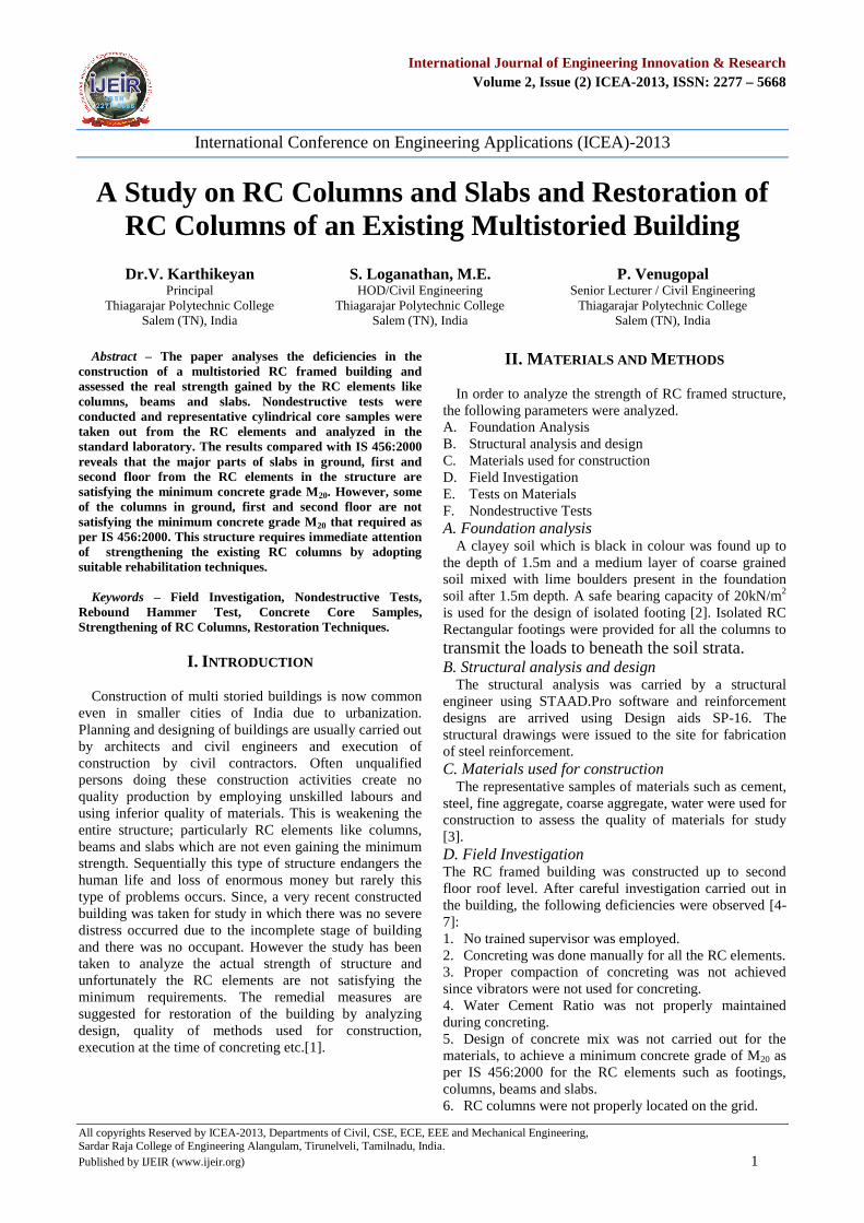
F. Nondestructive TestsNondestructive tests were conducted on RC elements
such as columns, beams and slabs to find out the actualstrength gained by them. Fig.1 is the layout pointing thecolumns which have been tested in the building.
Fig.1. Layout pointing the tested columns
1) Rebound Hammer Test: A Preliminary investigationwas conducted to find out the surface hardness of theconcrete by using Rebound Hammer at columns and slabsin various locations [12-13]. The test results are astabulated in Tables 7 and 8.
Table 7: Rebound Hammer Test on Columns
RCelements Floor Location
CompressiveStrength(MPa)
Columns
Ground FloorB2 9B4 10C5 10
First Floor C6 10Second Floor B5 9Third Floor B4 9
Table 8: Rebound Hammer Test on slabs
RCelements
Floor LocationCompressive
Strength(MPa)
Slabs
GroundFloor
A2-B2 & A3-B3 12D4-B4 & D5-C5 10.8
FirstFloor
D2-C2 & D3-B3 14.4A2-B2 & A3-B3 10.2
SecondFloor
C2-D2 & C3-B3 8C6-D6 & C5-D5 4.4A6-B6 & A7-B7 3.6A2-B2 & A3-B3 5.5
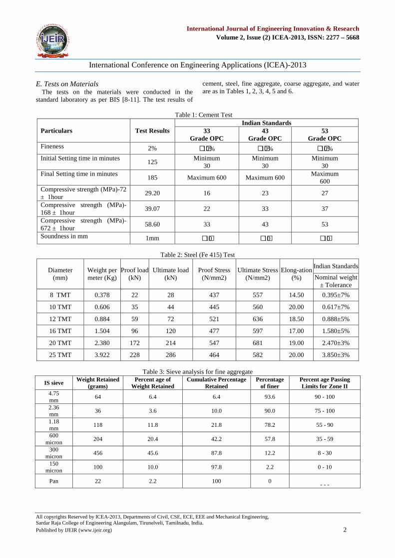
2) Core Sampling Test: Core sampling test is the mostappropriate method to assess the strength of in-situreinforced concrete construction [14]. A Profoscope–Reinforcement locater was used as shown in Fig.2 toidentify the reinforcing rods so that cutting of the samemay be avoided to the extent possible.
Fig.2. A View of the Profometer being used to identify thereinforcement in column
International Conference on Engineering Applications (ICEA)-2013
All copyrights Reserved by ICEA-2013, Departments of Civil, CSE, ECE, EEE and Mechanical Engineering,Sardar Raja College of Engineering Alangulam, Tirunelveli, Tamilnadu, India.Published by IJEIR (www.ijeir.org) 4
International Journal of Engineering Innovation & ResearchVolume 2, Issue (2) ICEA-2013, ISSN: 2277 – 5668
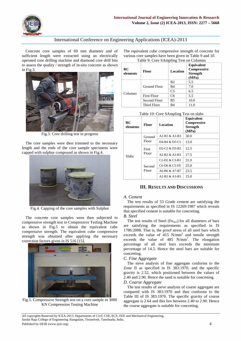
Concrete core samples of 69 mm diameter and ofsufficient length were extracted using an electricallyoperated core drilling machine and diamond core drill bitsto assess the quality / strength of in-situ concrete as shownin Fig.3.
Fig.3. Core drilling test in progress
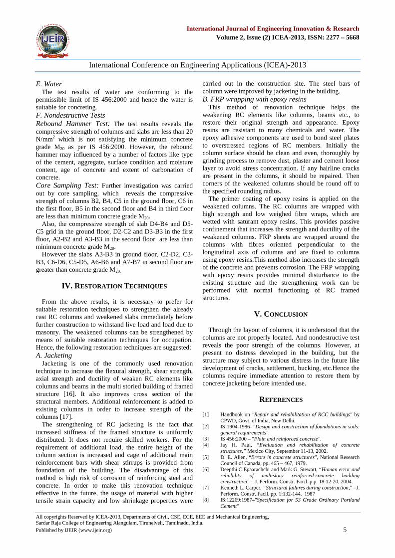
The core samples were then trimmed to the necessarylength and the ends of the core sample specimens werecapped with sulphur compound as shown in Fig.4.
Fig.4. Capping of the core samples with Sulphur
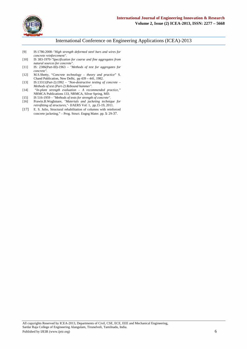
The concrete core samples were then subjected tocompressive strength test in Compressive Testing Machineas shown in Fig.5 to obtain the equivalent cubecompressive strength. The equivalent cube compressivestrength was obtained after applying the necessarycorrection factors given in IS 516 [15].
Fig.5. Compressive Strength test on a core sample in 3000KN Compression Testing Machine
The equivalent cube compressive strength of concrete forvarious core samples have been given in Table 9 and 10.
Table 9: Core SAmpling Test on Columns
RCelements Floor Location
EquivalentCompressiveStrength(MPa)
Columns
Ground FloorB2 5.5B4 7.0C5 6.5
First Floor C6 5.5Second Floor B5 10.0Third Floor B4 11.0
Table 10: Core SAmpling Test on slabs
RCelements
Floor Location
EquivalentCompressiveStrength(MPa)
Slabs
GroundFloor
A2-B2 & A3-B3 30.0
D4-B4 & D5-C5 13.0
FirstFloor
D2-C2 & D3-B3 12.5
A2-B2 & A3-B3 17.5
SecondFloor
C2-D2 & C3-B3 31.0
C6-D6 & C5-D5 25.0
A6-B6 & A7-B7 23.5
A2-B2 & A3-B3 15.0
III. RESULTS AND DISCUSSIONS
A. CementThe test results of 53 Grade cement are satisfying the
requirements as specified in IS 12269:1987 which revealsthat specified cement is suitable for concreting.B. Steel
The test results of Steel (Fe415) for all diameters of barsare satisfying the requirements as specified in IS1786:2008. That is, the proof stress of all steel bars whichexceeds the value of 415 N/mm2 and tensile strengthexceeds the value of 485 N/mm2. The elongationpercentage of all steel bars exceeds the minimumpercentage of 14.5. Hence the steel bars are suitable forconcreting.C. Fine Aggregate
The sieve analysis of fine aggregate conforms to theZone II as specified in IS 383:1970, and the specificgravity is 2.52, which positioned between the values of2.40 and 2.90. Hence the sand is suitable for concreting.D. Coarse Aggregate
The test results of sieve analysis of coarse aggregate arecompared with IS 383:1970 and thus conforms to theTable III of IS 383:1970. The specific gravity of coarseaggregate is 2.64 and this lies between 2.40 to 2.90. Hencethe coarse aggregate is suitable for concreting.
International Conference on Engineering Applications (ICEA)-2013
All copyrights Reserved by ICEA-2013, Departments of Civil, CSE, ECE, EEE and Mechanical Engineering,Sardar Raja College of Engineering Alangulam, Tirunelveli, Tamilnadu, India.Published by IJEIR (www.ijeir.org) 5
International Journal of Engineering Innovation & ResearchVolume 2, Issue (2) ICEA-2013, ISSN: 2277 – 5668
E. WaterThe test results of water are conforming to the
permissible limit of IS 456:2000 and hence the water issuitable for concreting.F. Nondestructive TestsRebound Hammer Test: The test results reveals thecompressive strength of columns and slabs are less than 20N/mm2 which is not satisfying the minimum concretegrade M20 as per IS 456:2000. However, the reboundhammer may influenced by a number of factors like typeof the cement, aggregate, surface condition and moisturecontent, age of concrete and extent of carbonation ofconcrete.Core Sampling Test: Further investigation was carriedout by core sampling, which reveals the compressivestrength of columns B2, B4, C5 in the ground floor, C6 inthe first floor, B5 in the second floor and B4 in third floorare less than minimum concrete grade M20.
Also, the compressive strength of slab D4-B4 and D5-C5 grid in the ground floor, D2-C2 and D3-B3 in the firstfloor, A2-B2 and A3-B3 in the second floor are less thanminimum concrete grade M20.
However the slabs A3-B3 in ground floor, C2-D2, C3-B3, C6-D6, C5-D5, A6-B6 and A7-B7 in second floor aregreater than concrete grade M20.
IV. RESTORATION TECHNIQUES
From the above results, it is necessary to prefer forsuitable restoration techniques to strengthen the alreadycast RC columns and weakened slabs immediately beforefurther construction to withstand live load and load due tomasonry. The weakened columns can be strengthened bymeans of suitable restoration techniques for occupation.Hence, the following restoration techniques are suggested:A. Jacketing
Jacketing is one of the commonly used renovationtechnique to increase the flexural strength, shear strength,axial strength and ductility of weaken RC elements likecolumns and beams in the multi storied building of framedstructure [16]. It also improves cross section of thestructural members. Additional reinforcement is added toexisting columns in order to increase strength of thecolumns [17].
The strengthening of RC jacketing is the fact thatincreased stiffness of the framed structure is uniformlydistributed. It does not require skilled workers. For therequirement of additional load, the entire height of thecolumn section is increased and cage of additional mainreinforcement bars with shear stirrups is provided fromfoundation of the building. The disadvantage of thismethod is high risk of corrosion of reinforcing steel andconcrete. In order to make this renovation techniqueeffective in the future, the usage of material with highertensile strain capacity and low shrinkage properties were
carried out in the construction site. The steel bars ofcolumn were improved by jacketing in the building.B. FRP wrapping with epoxy resins
This method of renovation technique helps theweakening RC elements like columns, beams etc., torestore their original strength and appearance. Epoxyresins are resistant to many chemicals and water. Theepoxy adhesive components are used to bond steel platesto overstressed regions of RC members. Initially thecolumn surface should be clean and even, thoroughly bygrinding process to remove dust, plaster and cement looselayer to avoid stress concentration. If any hairline cracksare present in the columns, it should be repaired. Thencorners of the weakened columns should be round off tothe specified rounding radius.
The primer coating of epoxy resins is applied on theweakened columns. The RC columns are wrapped withhigh strength and low weighed fibre wraps, which arewetted with saturant epoxy resins. This provides passiveconfinement that increases the strength and ductility of theweakened columns. FRP sheets are wrapped around thecolumns with fibres oriented perpendicular to thelongitudinal axis of columns and are fixed to columnsusing epoxy resins.This method also increases the strengthof the concrete and prevents corrosion. The FRP wrappingwith epoxy resins provides minimal disturbance to theexisting structure and the strengthening work can beperformed with normal functioning of RC framedstructures.
V. CONCLUSION
Through the layout of columns, it is understood that thecolumns are not properly located. And nondestructive testreveals the poor strength of the columns. However, atpresent no distress developed in the building, but thestructure may subject to various distress in the future likedevelopment of cracks, settlement, bucking, etc.Hence thecolumns require immediate attention to restore them byconcrete jacketing before intended use.
REFERENCES
[1] Handbook on "Repair and rehabilitation of RCC buildings" byCPWD, Govt. of India, New Delhi.
[2] IS 1904-1986- "Design and construction of foundations in soils:general requirements".
[3] IS 456:2000 – "Plain and reinforced concrete".[4] Jay H. Paul, “Evaluation and rehabilitation of concrete
structures,” Mexico City, September 11-13, 2002.[5] D. E. Allen, “Errors in concrete structures”, National Research
Council of Canada, pp. 465 – 467, 1979.[6] Deepthi.C.Epaarachchi and Mark G. Stewart, “Human error and
reliability of multistory reinforced-concrete buildingconstruction” – J. Perform. Constr. Facil. p p. 18:12-20, 2004.
[7] Kenneth L. Carper, “Structural failures during construction,” –J.Perform. Constr. Facil. pp. 1:132-144, 1987
[8] IS:12269:1987–"Specification for 53 Grade Ordinary PortlandCement"
International Conference on Engineering Applications (ICEA)-2013
All copyrights Reserved by ICEA-2013, Departments of Civil, CSE, ECE, EEE and Mechanical Engineering,Sardar Raja College of Engineering Alangulam, Tirunelveli, Tamilnadu, India.Published by IJEIR (www.ijeir.org) 6
International Journal of Engineering Innovation & ResearchVolume 2, Issue (2) ICEA-2013, ISSN: 2277 – 5668
[9] IS:1786:2008–"High strength deformed steel bars and wires forconcrete reinforcement".
[10] IS 383-1970-"Specification for coarse and fine aggregates fromnatural sources for concrete".
[11] IS: 2386(Part-III)-1963 – "Methods of test for aggregates forconcrete".
[12] M.S.Shetty, “Concrete technology – theory and practice” S.Chand Publication, New Delhi, pp 439 – 441, 1982.
[13] IS:13311(Part-2):1992 – "Non-destructive testing of concrete –Methods of test (Part-2) Rebound hammer".
[14] “In-plant strength evaluation – A recommended practice,”NRMCA Publications 133, NRMCA, Silver Spring, MD.
[15] IS 516-1959 – "Methods of tests for strength of concrete".[16] Prawin.B.Waghmare, "Materials and jacketing technique for
retrofitting of structures,"- IJAERS Vol: 1, pp.15-19, 2011.[17] E. S. Julio, Structural rehabilitation of columns with reinforced
concrete jacketing,” – Prog. Struct. Engng Mater. pp. 5: 29-37.