Embed Size (px)
Citation preview

HILLINOI SUNIVERSITY OF ILLINOIS AT URBANA-CHAMPAIGN
PRODUCTION NOTE
University of Illinois atUrbana-Champaign Library
Large-scale Digitization Project, 2007.


-MiWAY1 IN j11 -19D F w a
UNIVERSILTY ,.OF ILLI NOIS BULLETINVol. IV. AUQUST 19, 1907 No. 32
tatered Feb. 14, 1902, at Urbana. Illinois as secoid-class matter under Aqt of CongressJuly 16, 18941.
44
.BULLETIN NO. 16 .
A STUDY OF ROOF TRUSSES 4
N. CLIFFORD RICKER
- :s ..... lu •ll
;i. ,:l !
i'f^;-:
'x n i a ~ c
>4 4, 4
-7,
4 ,. I
44 4
447, ,4 .. 44 44
4 4 .4
A . >4
'4 .4
7,44
44
7,444 4>>4 444 4
44
4 4.
>44
'.4 7, "44
444 4 4.4,4
,4'44 >447,
7,
4y~,
7,4 4 *4~4
UIVERSITY OE ILLUNOIS7, ~1RINQ EX~tRXMENTV 81rATON,
A 44 IMS^I, .4>4 4, , ''.:!^^
>4 ;4 -4 4 4^4 4'4'44
^ * >4>4 >4, ^ ^ 1
^?. -^ '4 4 47,7, 4
4)
7,;
~ 444
7,47,
447,4,444>4
>4>4
444~
^
(-

H E, Engineering Experiment Station was established byT action of the Bfoard of Trustees December '8, 1903. Itj is the purpose of the Station to carry on investigations- along various lines of engineering, and to study prob-
lems of importance to professional engineers and to the manufac-turin'g, railway, mining, constructional and industrial interests ofthe state.
The control of the Engineering Experiment Station is vestedin the heads of the several departments of the College of Engi-neering. These constitute the Station Staff, and with theDirector determine the character of the investigations to be under-taken. The work is carried on under the supervision of the Staff;sometimes by a Research Fellow as graduate work, sometimes bya member 'of the instructional force of the College of Engineering,but more frequently by an investigator belonging to the Stationcorps.
The results of these investigations will be published in theform of bulletins, and will record mostly the experiments of theStation's own staff of investigators. There will alseo be issuedfrom time to time in the form of circulars, compilations givingthe results of the experiments of engineers, industrial works,technical institutions and governmental testing departments.
The volume and number at the top of the title page of thecoverI are merely arbitrary nnumbers and refer to the general pub-lications of the University of Illinois; above the title, is given thenumber of the Engineering Experiment Station bulletiv, or circutar,which should be'used in referring to these publipations,
For copies of bulletins, circulars or other information, addressthe Engineering Experiment Station, "Urbana, Illinois .
'.4
4.
4, j 44 ~ 4-A ,.
~ 4. '4 4 .4.
4-'- '4' .4
4 '44 (4
4 ~ 44 r ~ ~ 444
4 4-*.-~ ~4y' ' 4 44 4
'4. -4.--... ~;4v-.4 ~ ~ 44.' '-4 4 ~ 4'~'<~
'-u~~"'j " 4"'- 4 "*"~ .,, 4 4.~A ~- " 4 4 -'4-'A'- .- * 4"~44. '444444y~ ~4, 4'~'~'4'44 ' 4. '4>'~ ' ~-' .44,
4.4.44~ 44 "s' .44 4,4
-4< 4''-444\ ~ 4; '-4.44~4 ~ .444 4'4~'4 A 444~- 44
(4 ~'
4 4
>4 4,
4 44
~- 4.'
N 'A 7,4
4~44-, ~
4 ~4" ~29~
4444-444
~ 44/ 4 - 4." 4 -4 4 44,
~-4444 44 4 4

SiONI-- '•VNv9un'SIONIiii JO AIIS93AINn
'IIN3WIVd30 9NIy33NIDN3 AVM1IW4
RAILWAY ENGINEERING DEPARTMENT,UNIVERSITY OF ILLINOIS,
URBANA, ILLINOIS.
UNIVERSITY OF ILLINOIS
ENGINEERING EXPERIMENT STATION
BULLETIN No. 16 AUGUST 1907
A STUDY OF ROOF TKUSSES
BY N. CLIFFORD RICKER. D. ARCH., PROFESSOR OF ARCHITECTURE
The investigation described in this bulletin had for its originalobject the determination of a formula for the weight of roof
trusses more accurate than those now in existence. As the inves-
tigation progressed, however, other topics arose and some inter-
esting results were secured, which it is believed will be of value
to architects and engineers. Very little study has been devotedto roof trusses in comparison with the thorough treatment of bridge
trusses by eminent writers. The chief result of the work has
been the devising of a method to save time and labor by present-ing data in a form most convenient for comparison. This systemwill be found convenient in calculating and designing roof trussesto satisfy given conditions, whether constructed of wood and steel,or entirely of steel.
I. METHOD OF INVESTIGATION
In the determination of weights, general mathematical methodsmay be readily applied to most forms of bridge trusses, especiallythose with parallel chords; these are, however, less valuable forroof trusses where far more varied conditions must be arbitrarilylimited in order to make such methods applicable. The resultsare then of doubtful worth. A more practical method of inves-
tigation was therefore chosen. For a single common type oftruss, Fig. 2, nearly fifty trusses of varied span, rise, and dis-tance apart were calculated and designed in the same general

2 ILLINOIS ENGINEERING EXPERIMENT STATION
way. Next the weight of each truss was carefully computed, andif this materially differed from the assumed weight of the truss,the necessary corrections were made in the sectional dimensionsand weight of members.
The verticals were steel rods with upset ends; all other mem-bers were long leaf pine timbers. Splices in the tie-beam and itsconnection with the principal were made with vertical steel fishplates and through bolts. A purlin rested on each apex of theprincipal and supported the rafters on which was laid i-in.matched sheathing covered by a painted tin roof.
In accordance with the usual custom of engineers the roofwas assumed to support a snow load and wind pressure at thesame time, although the writer believes that this extreme condi-tion rarely occurs. The assumption, however, provides somesurplus strength for contingencies, such as unusual snowfall, veryviolent winds, etc.
II. CONDITIONS ASSUMED
The spans of the trusses were assumed to vary by 20-ft.intervals from 20 to 200 ft.
The rise of the trusses was varied by 5-ft. intervals from A toi the span.
The distance between trusses was varied by 5-ft. intervalsfrom 10 to 30 ft.
The horizontal panel length was varied from 10 to 25 ft.The number of purlins per panel was varied from 1 to 5.
III. LOADS SUPPORTED BY A TRUSS
1. Permanent loads
The following are the permanent loads assumed:Painted tin covering .............. 2 lb. per sq. ft.Long leaf pine lumber............ 4 lb. per sq. ft. B. M.Steel (see Cambria, etc.)..........480 lb. per cu. ft.Cast iron ........... ...... . .. 450 lb. per cu. ft.Weight of truss........... ...... Assumed
The weights of trusses were first assumed in accordance withMerriman and Jacoby's formula; but the following formula wasdeduced from the results of this investigation and is found toagree more closely with the computed weights of the trusses ex-amined:
URBANA, ILUNOIS.
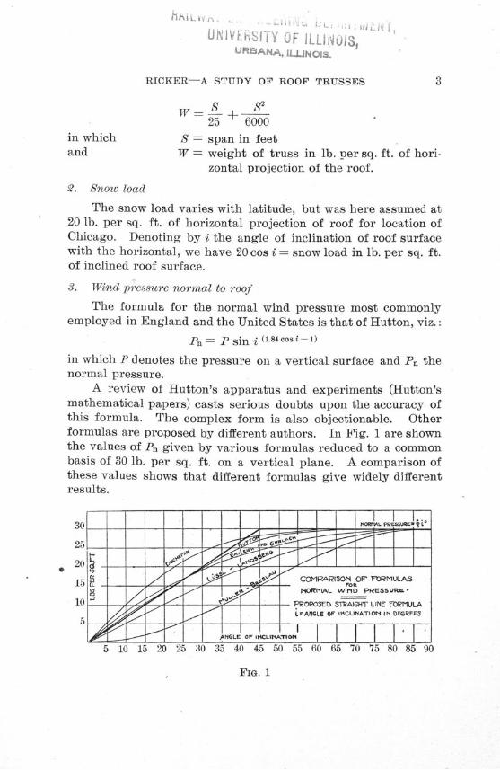
RICKER-A STUDY OF ROOF TRUSSES 3
S S2
25 ± 6000in which S = span in feetand W = weight of truss in lb. per sq. ft. of hori-
zontal projection of the roof.
2. Snow load
The snow load varies with latitude, but was here assumed at20 lb. per sq. ft. of horizontal projection of roof for location ofChicago. Denoting by i the angle of inclination of roof surfacewith the horizontal, we have 20 cos i = snow load in lb. per sq. ft.of inclined roof surface.
3. Wind pressure normal to roof
The formula for the normal wind pressure most commonlyemployed in England and the United States is that of Hutton, viz.:
Pn P sin i (1.84cosi-1)
in which P denotes the pressure on a vertical surface and Pn thenormal pressure.
A review of Hutton's apparatus and experiments (Hutton'smathematical papers) casts serious doubts upon the accuracy ofthis formula. The complex form is also objectionable. Otherformulas are proposed by different authors. In Fig. 1 are shownthe values of Pn given by various formulas reduced to a commonbasis of 30 lb. per sq. ft. on a vertical plane. A comparison ofthese values shows that different formulas give widely differentresults.
FIG. 1

4 ILLINOIS ENGINEERING EXPERIMENT STATION
Mtller of Breslau is the greatest living authority on graphicstatics and probably on the theory of bridges and roofs; hisformula, however, gives the smallest values for normal windpressures. It is evident that very little is certainly known con-cerning the relation between horizontal and normal wind pres-sures; hence the following empirical formulas were here adoptedas being sufficient and convenient in use:
Taking the angle i in degrees,Pn = I i, for P = 30 lb. per sq. ft. horizontal pressure.Pn = % i, for P = 40 lb. per sq. ft. horizontal pressure.Pn = 1 0 i, for P = 50 lb. per sq. ft. horizontal pressure.
These formulas are applicable for values of i less than 450for higher inclinations, the normal and horizontal pressures areequal. They were believed to be original, but it has since beenfound that similar formulas had already been published.
IV. APPLICATION OF THE METHOD TO A TRUSS
The treatment of a specimen truss will most clearly explainthe method employed.
1. Assumptions
Let the following program be assumed:Span of truss - 200 ft.; rise = 50 ft.; trusses set 20 ft. apart on
centers; 20 panels of 10 ft. each; i = 26.5°. Roof covered withpainted tin, laid on matched sheathing, supported by rafters rest-ing on one purlin fixed on each apex of principal. Vertical rods,splice plates, and bolts to be of steel; other members to be longleaf pine timbers.
The following values are readily found:Panel length of principal = 11.18 ft.Panel area of roof surface = 223.6 sq. ft.Snow load on roof surface = 20 cos i = 17.9 lb. per sq. ft.Normal wind pressure on roof surface = # i = 17.7 lb. per
sq. ft.
2. Sheathing
. To determine the maximum safe length L of sheathing be-tween rafters we proceed as follows:
Vertical load on sheathing = 2 lb. (tin) + 4 lb. (sheathing) +17.9 lb. (snow) = 23.9 lb. per sq. ft.

RICKER-A STUDY OF ROOF TRUSSES
This load is resolved into a normal component, acting at rightangles to surface of sheathing, and into a component parallel to thesurface. The latter may be neglected, since it is resisted amplyby the edgewise strength of the sheathing. The normal compo-nent is 23.9 cos i = 21.4 lb. per sq. ft. Adding to this the normalwind pressure, we get for the total normal load on the sheathing
21.4 + 17.7 = 39.1 lb. per sq. ft.Let L = distance in ft. between centers of rafters
t = thickness of sheathing in inches.For safety against breaking the sheathing we have
L = 43.2 43.2x.875 6.05 ft.L 4 w / 3 9 .1
For deflection limited to s-~ of length,
Lt 12.9x .875L = 12.9 - = 3.33 ft.
I w 039.1
Hence the rafters can not be spaced more than 3.33 ft. betweencenters.
S. Rafters
Assuming 2-in. by 6-in. rafters, the maximum safe distancebetween their centers is determined as follows:
Let e = distance between centers of rafters in inches;- section modulus = 12 for 2-in. by 6-in. cross-section.
c
I = moment of inertia = 36 for 2-in. by 6-in. cross-section.The values of the section modulus and moment of inertia may
be found without calculation by means of Tables 1 and 2.The vertical load on rafters is 2 lb. (tin) + 4 lb. (sheathing) +2 lb. (rafters) + 17.9 lb. (snow) = 25.9 lb. per sq. -ft.Hence the normal load on the rafters is 25.9 cos i + 17.7 (wind)= 40.9 lb. per sq. ft.; and the load parallel to the rafters actinglengthwise and producing longitudinal compression in them is25.9 sin i = 11.6 lb. per sq. ft.
For safety against breaking,
11200 I 11200 x 12e -- - 0 x121-= 26. 3 in. between centers of rafters.wLo , 40.9 x 11.182

6 ILLINOIS ENGINEERING EXPERIMENT STATION
TABLE 1
TABLE OF VALUES OF SECTION MODULUS-C
For Rectangular Wooden Timbers
inches
1 2 3 4 6 8 10 122 1 1 2 3 4 5 7 84 3 5 8 11 16 21 27 326 6 12 18 24 36 48 60 728 11 21 32 43 1 64 85 107 128
10 17 33 50 67 100 133 167 20012 24 48 72 96 144 192 240 28814 33 65 98 131 196 261 327 39216 43 85 128 171 256 341 427 51218 54 108 162 216 324 432 540 648
1493784
149233336457598756
16114296
171267384523683864
181248
108192300432588768972
TABLE 2
TABLE OF VALUES OF SECTION MOMENT OF INERTIA I
For Rectangular Wooden Timbers
inches
2468
1012141618
1 2 31 1 25 11 16
18 36 5443 85 12883 167 250
144 288 432229 457 686341 683 1024486 972 1458
4 63 4
21 3272 108
171 256333 500576 864915 1372
1365 20481944 2916
85
43144341667
1152182927313888
10753
180427833
.1440228734134860
12 148 9
75252149
11672016320147796804
64216512
10001728274440965832
16 1811 1285 96
288 324171 192
1333 15002304 25923659 41165461 61447776 8748
For safe limit of deflection,30223 I 30223x 36
e wL- - 40.9 11.18 -- 19.2 in. between centers of rafters.
Since the rafters are dressed smaller than 2 in. by 6 in., it is bestto space them 16 in. between centers instead of 19.2 in., thusmaking 15 equal spaces per bay of the roof.
The deflection A of the rafters at the middle of their lengthis
3 wL 4e 3 x 40.9 x 11.184 x 16A 2720000 1 2720000 x 36 .315 in.

RICKER-A STUDY OF ROOF TRUSSES
The total longitudinal load on one rafter is
11.6 x 1i x 11.18 = 173 lb.
One-half this, or 86.5 lb., acts on the cross-section at mid-lengthof the rafter. If the rafter is straight, this compression would beuniformly distributed over the cross-section, thus giving86.512-- 7.2 lb. per sq. in. compression. But after the rafter has
deflected .315 in., the compression in the upper fibers of the cross-section is increased to
p = p(l + 6 ) = 7.2 (1 + 6 315) = 9.5 lb. per sq. in.,d 6
where p = uniform compression in lb. per sq. in. at mid-length, and d = depth of rafter in inches.
If the load is expressed in tons, we havep' = 9.5 lb. per sq. in. = .0048 ton per sq. in. of cross-
section. The compression p' must be deducted from the safe fiberstress of long leaf pine timbers in tons per sq. in. to obtain thesafe value for this case. Taking 0.7 tons per sq. in. as this safestress, we obtain, therefore, .7000 - .0048 = .6952 ton per sq. in.as the net safe fiber stress for long leaf pine timbers.
Let this be denoted by F; then for safety against breaking
and compression:16000 Fl _ 16000 x .6952 x 12
- wLc 40.9 x 11.182 = 26.Oin. = maximum
distance between centers of rafters in inches.It is evident from this analysis that the parallel loading and
the longitudinal compression thereby caused in rafters may gener-ally be neglected except for very steep roofs.
4. PurlinsThe weight of the purlin being unknown is at first neglected.
The total loading on a purlin may be resolved into two compo-nents, one normal to the roof, the other parallel thereto.
Denoting these components by W and W' respectively, wehave
223.6 x 40.9W = 2000 = 4.57 T., the normal loading,
2000

8 ILLINOIS ENGINEERING EXPERIMENT STATION
For normal loading
- 2.14 WL = 2.14 x 4.57 x 20 = 195.2c
I =- .795 WL'= .795 x 4.57 x 20' = 1453For parallel loading
- = 2.14 WL = 2.14 x 1.30 x 20 = 55.6c
I = .795 WL 2 = .795 x 1.30 x 20' = 413From Tables 1 and 2 we select a cross-section for the purlin
such that the values for and I (edgewise for normal loading andcflatwise" for parallel loading) are not less than those just found.A cross-section 8 in. x 14 in. is found to satisfy the four condi-tions just determined.
The weight of the purlin is therefore8x14x4x208x14 x 4x2 = 747 lb. = .374 T.
12The normal component of the weight is
.374 cos i = .33 T.and the parallel component of the weight is
.374 sin i = .17 T.Adding these to previous values, we find TV = 4.90 T. and
W = 1.47 T.
Using these new values of W and W', we obtain for and Ic
the following results:For normal loading
I- = 2.14 x 4.90 x 20 = 209.3C
I = .795 x 4.90 x 202 = 1558For parallel loading
-= 2.14 x 1.47 x 20 = 59.6c
I = -.795 x 1.47 x 202 = 443Referring again to Tables 1 and 2, we find that a purlin
8 in. x 14 in. is still amply sufficient to support both its load andits own weight.

RICKER-A STUDY OF ROOF TRUSSES
5. Weight of trussUsing the formula given in Art. 3, we obtain for the weight
of truss_+__
2 200 2002- -200= 141 lb. per sq. ft. of
25 6000 25 6000horizontal projection of roof.6. Computation of apex loads
Permanent loads:Covering,sheathing and rafters,223.6 x 8 = 1789 lb.
Purlin, as before 747 lb.
Truss 200 x 14 2933 lb.5469 lb.= 2.735 T.
Snow load 200 x 20 = 4000 lb. = 2.000 T.
Wind load 223.6 x 17.7 = 3958 lb.= 1.979 T.
7. Computation of loading on one-half trussPermanent loading 2.735 x 91 = 25.98 T.
Snow loading 2.000 x 91 = 19.00 T.
Wind loading 1.979 x 91 = 18.80 T.
8. Truss diagram, stress diagrams, and stress sheet
Having the loads, the truss diagram is drawn, and the stress
diagrams are then drawn for permanent and wind loadings
FIG 2 TRU L)DAbiAll
ST1iG4 WIND STRESS DIAGRAM
FIG. 2, 3, 4

10 ILLINOIS ENGINEERING EXPERIMENT STATION
a) a) a) a) C3 (1.) WD C) c a) a.) a) [Da) C) 0 C a) C> a)tobt ~hhbn U Ubp Ubp c hC B& ho b&o i ho &bo U ho
eccc aa or OCCGCr. CGa=ca Cd d ca ca ca ca ca ac aca!? ctca ca ca rtcar
00000 00000 00000 0000
m^^0O Co m O = - 11: <= m Lm C9; Lo 00 -' +-lr- -ý~r~q 0) CC)P C C 0 00 x0
oc r- w 41: Cor-11, co fi 'm xr- o oo m- CA
_;lM'l- 14 _; _; !T-14 _ (Mi 1; _; -r- ý* 14 _; 14
00 00 0D c1 lz cc0 0c c cc 00000 0000
000~ 00~00
t- -<-h-^ - - - -^ -H ---- OOO - - -- -
.0^ 0,0 .0.0.0.0.0 -0..00 .0.0.0.0
oCo cý < m,: x me m aq
*- - - * - ^ -H '- ,^ r^ - -^ ri j^- 1 *^^^+
0 C 00000 0000
x0 wrC 4 m CA x m00 r mC
C-l--(OO rr-r 04000 00-0
| +
C^-IO CO C05O^M -OOQOO OO~t0
es J- j' o c o o^cs ~10c >io i-1 c ±
r- 00 14O 4.) ID aO t i li C ý C COO'iC^ ^QaO ! O -OOr-i r 00 - 0 0000 C0
01 CA C 00 M 'ýz r
ýXXX ýl'X ! xt i >ýP- ýýý> >, <
suoisuon!Q(
pojoal.OD
sseojsmnmuhxxB
ssa3jS 'UmjoIjo ssooxa
suocqoauuooJo
qq4tam
uqi 'o3oAS
[juoitooS
ssajlSmniuIx'BpI
ssaes puTMA
ssoeas AouS
ssajcisquounjoa%
jaqTuuoi

RICKER-A STUDY OF ROOF TRUSSES
a) a) a) 4 a.) W wD a) 0 0 a) a) a) wy w a)&hccc &hoh oh be ho bC b 0 ho bono boh& _cacacc caOecca csae am a
coooo ooooooc ooo -oo 03003000 0000000 0 00 00
cq V. i- 0 i -- "t 00 - CC C > m- - r-( =T- cel S^ 0CA~ ZZ "IZmZall L:----------
00
r^r- S1CTTO W-f-T10 1CM' O r-1' o
1 ~ 0
I +
m 0 r-^ r-100 w = km -t 00 c r-M q 0 m
all^ CAC M m-'-
0000000000
C0000 00CD00-0000 000^2 ;^ C1 c r4 c)1-i o 1=S41.) C> V3 0 ko to 0
A in 000 LM 0000 0 m0 cc 0
SSS^^a cq vT m3 + ý- r a N NT X- 0
Ocq ®^» Vz Xm 0 " cq M "t L2o C)5t~
I r r -
oi~ or-o 0
N cc -d LoU r- 00 C0 m I0 00 1- 00 00+
Cic r-00 r 0 NkO = o
00 C rý Cq -1 cl rV1 C6 a
0 aS'-tCO 0O in I- 00ffq .dl 00 - T- r ý M 4z I- = 1r-Tl- r~<-I
t-c~d 0 i(m m Is L- C9l *t<o 00 0 q -It cc wo1.4 1.4 1" . "H l-4 i-4 11 r-l
I I
+
0sHT-<OT

ILLINOIS ENGINEERING EXPERIMENT STATION
SAFE RESISTANCE OFWOODEN POSTS AND STRUTS
IN TONS N. CLIFFORD RICKER
FIG. 5 LENGTH IN FEET
12>•

RICKER-A STUDY OF ROOF TRUSSES
The magnitude of each stress is measured and written in theproper column and space of the stress sheet.
Since the diagram for snow stresses would be exactly similarto that for permanent stresses, it need not be drawn, but the snowstresses can be quickly found with a good slide rule, using thefollowing proportion:
25.98 : 19.00 = permanent stress : snow stress.It is best to tabulate the permanent, snow and wind stresses
separately, to permit taking any combination of them as the max-imum stress on the members.
Maximum stresses are here found by taking the sum of thestresses on each member.
9. Sections of members
Principals and struts are in compression, and their sectionaldimensions are most conveniently found by the graphical table,Fig. 5, based on a modified form of Stanwood's formula, for yel-low pine columns, viz.:
p - .7 00 -. 08 4 Ld
where p = safe compression in tons per sq. in.L = free length of timber in feetd = least side in inches
(a) Principals
The length of the principal is 11.18 ft.; and from the stresssheet the maximum compression in X 1 is 125.5 tons. Hence bythe table (Fig. 5) the section of principal should be 14 in. x 14in. For convenience in construction and better appearance, theprincipals are made of uniform section throughout their entirelength.
(b) .Struts
The struts are most conveniently framed and look best ifm.ade the same breadth as principal, so as to be flush on eachside. They are here 14 in. wide, and their safe thickness ordepth is found by the table.
(c) Tie-beam
The tie-beam is to be made the same breadth as principalsand struts. The safe resistance of long leaf pine to tension is

14 ILLINOIS ENGINEERING EXPERIMENT STATION
taken as 0.6 ton per sq. in. Then if b is the breadth of the tie-beam in inches and d the depth, we have
maximum tension 117.8 14.0 in.0.6 x b 0.6 x 14
Assuming that 3 horizontal rows of 1-inch bolts are to be
used in splices, we should make the total depth 14 + 3 = 17 in.,
or say 18 in.
(d) Vertical steel rods
The table for rods, nuts, washers, etc., is based on a safetensile stress of 7.5 tons per sq. in. for net section of rods,
whose ends are upset to standard diameters. The bearing areas
and diameters of washers are based on a maximum safe pressureof A ton per sq. in. on long leaf pine.
TABLE 4
TABLE OF STEEL RODS FOR LONG LEAF PINE TIMBERS
Diame- *ter of 4 )Rod ,
inches
4 1.471.872.30
S 2.784 3.32
4 3.897 4.51
47 5.181 5.891 ' 6.651i 7.461- 8.3111 9.201A 10.1511 11.141A, 12.171 13.251I 14.391 15.561- 16.781I 18.04
Cast ironUpset Ends Sq. N uts Round
inches inches Washersinches
I by 443 by 44- by 4l
1 by 411 by 441I by 441. 1 by 4411 by 4-11 by 51 by 514 by 51I by 54l1 by 5414 by 511 by 51li by 542 by 542 by 5j24 by 5424 by 542- by 51
t by 1-I by 14, by 1I
1 by 1I1 by 141 by 211 by 241i by 2417 by 241 3 by 2414 by 314 by 3It by 3114 by 34li by 34
2 by 42 by 42W by 424 by 424 by 44
I by 2I by 21ýj by 3j
1 by 3•71 by 311I by 461i by 43-11 by 4A%17 by 511 by 511i by 5&i1I by 5j1- by 6A14 by 641I by 61li by 7i2 by 71-2 by 7t24 by 824 by 8-521 by 854
U)
0
4O
4.936.137.599.23
10.8512.7714.8816.4019.2121.5724.3026.8529.8433.0336.0039.4643.0046.5150.4454.1(58.32
.67
.851.041.261.501.762.042.352.673.013.383.774.174.605.055.526.01.6.527.057.608.18
.24242i222li
141i14li1
1414111l11114
3.483.965.767.708.54
11.5615.0016.3421.7623.4228.8630.8437.4044.7047.4056.5666.2469.7678.7082.6095.06
Jý 04

RICKER-A STUDY OF ROOF TRUSSES
Divide the maximum tension in a member by the number ofrods composing it to find the stress in one rod; the diameter ofthe rod is then found in the table.
10. Splices in tie-beam and connections with principals
Splices in principals being in compression, they are simplehalved splices 1 foot long with two or four 1-inch bolts each, andare made as near the apex as possible.
Splices in tie-beams and connections of tie-beams with prin-cipals are calculated by the following formulas:Let t = thickness of one fish plate in inches.
R = number of horizontal rows of bolts.D = diameter of bolt in inches.b = breadth of tie-beam in inches.d = depth of the tie-beam in inches.a = distance in inches between centers of bolts or to end of
timber.N = total number of bolts in both ends of splice.Z = maximum longitudinal stress in member at splice or con-
nection.(a) Connection of tie-beam with principal.
For the thickness of the fish plate, we have
S-_ = _ 125.5-- =- .56 in. to resist tension.15 (d-R D) 15 (18-83 x 1)
t = .525 D = .525 x 1 = .53 in. to resist crushing against bolt.Therefore we make these fish plates each A% in. thick.a = 5 D = 5 in. between centers of bolts or to end of timber.The end of the fish plate is to be 2 in. outside the center of
the bolt.For the number of bolts, we have
N Z _ 125.5 = 24 one-in. bolts in the con-.375 Db .875 x 14 x 1
nection.These bolts must be symmetrically arranged about the axis
of the member, so that it becomes necessary to put some i-in.bolts in 1-in. holes to prevent the fish plates from buckling out-wards, being under compression.
(b) Splice in the member Y 5.Applying the same formulas, we find A-in. fish plates as be-
fore, and 20 one-in. bolts are required.(c) Splice in Y 11.

16 ILLINOIS ENGINEERING EXPERIMENT STATION
Fish plates must be -r1 in. thick, and 16 one in. -bolts are needed.(d) Splice at middle of truss.Fish plates should be a in. thick, and 12 one-in. bolts are
needed.11. Calculation of center length weights of members
The center length of each member is easily computed ormeasured on the truss diagram and it is then written on the stresssheet. This center length is then multiplied by the weight perlinear foot of the member, which is doubled to include both sidesof the truss (except for the middle vertical 18 18). These weightsare then written in the proper column of the stress sheet.
LI
k.0
.ATC5
FIG. 6
12. Calculation of weights of joints and connectionsThe differences between the actual and center length weights
of each member are next computed and written on the stresssheet.
The table of rods, etc., gives for rods their weight in poundsper linear foot, also the weight of the two upset ends, of two nuts,and of two cast-iron washers, but it does not include the portionsof rod between the intersection of the center lines of the trussmembers and the upset end of rod. This weight must be comput-ed and added to weight of rod ends, etc.
These weights of connections of members are written in thestress sheet.

RICKER-A STUDY OF ROOF TRUSSES
18. Computed weight of trussFrom the data presented in the preceding paragraphs, the
total weight of the truss may now be calculated. We have
Total center length weight of members ........... 51342 lb.Total net weight of connections ................... 3160 lb.
Total computed weight of truss......... 54554 lb.
Assumed weight of truss.................. .. ... 58660 lb.Deduct computed weight ......................... 54554 lb.
Excess of assumed weight over computed weight.. 4106 lb.
We have, therefore, excess per apex of principal=4106- 205.3 lb.
20
Whence the excess in permanent loading on one-half thetruss is
205.3 x 91-- 0.975 T.
2000
975This excess is 95. = .031 or 34 per cent of the permanent
load; hence permanent stresses in the stress sheet are 31 per centin excess. This excess is computed, written in the stress sheet,and deducted from the maximum stress. The corrected maximumstresses are thus found, since the snow and wind stresses on themembers are unchanged..
The sectional dimensions of members are next revised forthese corrected maximum stresses, the result being a slight re-duction in two members only. The corresponding reduction inweight is found to be 174 pounds.14. Final Summary
Net weight of wood in truss.............. ......... 45429 lb.Net weight of metal, nearly all steel................. 8777 lb.
Total net weight of truss................... 54380 lb.
Hence the weight of the wood is 831 per cent and the weightof the metal is 161 per cent of the total weight of truss.
The weight of the connections is 6f per cent of the centerlength weight of the truss.

18 ILLINOIS ENGINEERING EXPERIMENT STATION
Weight per square foot of horizontal projection of roof:Roof covering.......... . ........ . . 2.12 lb.Sheathing............................. 4.24 lb.Rafters .......... . . ............. 2.12 lb.P urlins ............... .............. . 3.74 lb.Truss.... .......... . ............. 13.58 lb.
Permanent load....... ............ 25.80 lb.Snow load............. ......... . 20.00 lb.W ind load...................... 17.70 lb. on in-
clined roof.
V. WEIGHTS OF TRUSSES OF DIFFERENT SPANS
Ten trusses were designed for spans of 20, 40, 60, 80, 100,120, 140, 160, 180, and 200 ft. respectively. The trusses wereset 20-ft. apart with a uniform rise of 4 span, the panel lengthsbeing 10 feet. Their weights were computed and plotted in Fig. 7,and the points connected by the broken line D. The increasingslope of this line shows that the weight of the truss increasesfaster than the span. The total permanent weight of the roof al-so increases with the span. The additional weight of the con-nections, however, diminishes very rapidly for spans less than60 ft. and varies irregularly for greater spans. Other weightsare constant.
VI. FORMULA FOR WEIGHT OF TRUSS
The following empirical formula for weights of long leaf pineand steel trusses is represented by the dotted line in Fig. 7, whichagrees well with the computed line D.
W= S+ + 0025 6000
where S = span in feetand W = weight of truss in lb. per sq. ft. of horizontal projec-
tion of roof.
VII. WEIGHT OF WHITE PINE AND STEEL TRUSSES
A series of trusses constructed of white pine timbers andsteel verticals was also designed and computed. The results ofthese computations are shown in Fig. 8. The preceding formula

RICKER-A STUDY OF ROOF TRUSSES
C) 0 0 0M -1
I I I N I I I I I I I I IHill H ill I
-------------- H ill -I----------------------------
aýz
A I
-----------
---- ----------------------
Xz" ý5 kz, -----------< ý, z I -- -----------
00
-----------
TTT M
WEIGHTS PER HORIZONTAL SQUARE FOOT
I II III I II i ii i iiiiii 111 11 1 11111U HIII I I Ri I I 1TMTW - 11 1

20 ILLINOIS ENGINEERING EXPERIMENT STATION
/CD
EIGHTS PER HORIZONTAL SQUA I OOT
/11 1 1 di l l I I 1
I\II I
WEIGHTS PER HORIZONTAL SQUARE: FOOT
0
0
4)
0 C
4)
4)
D 0ý
Z~CEo
pp)
z
P ~4
EI-1

RICKER-A STUDY OF ROOF TRUSSES
00
I
0
N
03
P4-.1
Eýz
P4
Eý
FIG. 9 SPAN IN FEET
is represented by the dotted line F, which here gives weightssomewhat exceeding those found by computation. In Fig. 9 isshown a comparison of the weights of trusses and also of the to-tal weights of roofs constructed of the two kinds of wood. Whitepine makes a somewhat lighter truss and roof than long leaf pine.However, in designing, it will be most convenient and accurate toapply the same formula and make the necessary reductions onthe stress sheet.
VIII. WEIGHT OF STEEL TRUSSES
Several steel trusses of different spans were also designedand computed. Their weights for spans of 100 and 200 feet werefound to be about the same as those of long leaf pine and steeltrusses. Therefore the formula is also applicable to steel trusses.It is very probable, however, that for short spans, steel trussesare somewhat heavier than those of wood and steel given by theformula; their connections are far more complex and certainlyrequire the addition of a larger per cent to the center lengthweights of truss. But these variations are taken into accounton the stress sheet.

22 ILLINOIS ENGINEERING EXPERIMENT STATION
IX. MOST ECONOMICAL DISTANCE BETWEEN TRUSSES
Trusses of 200-ft. span and 50-ft. rise spaced 10, 15, 20, 25and 30 ft. apart .respectively were designed and their weightswere computed. The results are shown in Fig. 10. The weight
FIG. 10. TRUSSES 200-FT. SPAN-50 FT. RISE
L. L. PINE WITH STEEL VERTICALS
20
-I.-,-
1)
DISTANCE BETWEEN TRUSSEs 0. C.
A-Weight of purlin.B-Per cent of total center length weights to be added for
weight of connections.C-Weight of covering, sheathing and rafters.D-Weight of truss.E-Total permanent weight.
of covering, sheathing, and rafters remains constant; the weightof the purlins and connections increases, and the weightof the truss diminishes as the distance between the trusses in-creases, being a minimum for a spacing of 25 ft. The totalweight of the roof, however, is a minimum when the trusses are15 ft. apart.
111.11111

RICKER-A STUDY OF ROOF TRUSSES
X. MOST ECONOMICAL SIZE OF PANELS
Trusses of 200-ft. span, 50-ft. rise, set 20 ft. apart, weredivided into 8, 10, 12, 14, 16, 18 and 20 panels to determine thebest length of panel. The results are given in Fig. 11 and show
FIG. 11. TRUSSES 200-FT. SPAN-50 FT. RISE-20 FT. ON CENTERS
L.L. PINE WITH STEEL VERTICALS
I-.- -_ -30
11 If1 20
EL ------ --- ------ ---------- ------- ---- ---- ---- ---------- ----- - ----------- ----- ---- ---- --- ---- ---
CI~.- . ......
2 ~ 2 ~ I III L - J - .1 - I - I J - J - -J
A I I I I14 16t 18 20
NUMBER OF PANELS
A-Weight of purlin.B-Per cent of total center length weights
weight of connections.C-Weight of covering, sheathing and rafters.D-Weight of truss.E-Total permanent weight.
to be added for
the following: (1) that the weight of covering, sheathing andrafters increases with the panel length; (2) the weight 'of thepurlins diminishes; (3) the weight of the truss, and very nearlythat of the entire roof, is a minimum for a panel length of 20 feet.Therefore 20-ft. panels appear to be most economical.
XI. BEST NUMBER OF PURLINS PER PANEL
For a series of trusses of like dimensions with panel lengthsof 25 ft. from 1 to 5 purlins were used on each panel length ofthe principal, which was therefore required to resist safely the
I i __ z-__-
A
"t

24 ILLINOIS ENGINEERING EXPERIMENT STATION
longitudinal compression and the stresses caused by the weightsof the purlins and their loads. The results are plotted in Fig. 12.These show (1) that the weight of the purlins increases with theirnumber; (2) the weight of covering, sheathing, and rafters de-
FIG. 12. TRUSSES 200-FT. SPAN--50 FT.-RISE-20 FT. ON CENTERSL. L. PINE WITH STEEL VERTICALS; EIGHT PANELS
§00
54
Zo'
CO
PURLINS PER PANEL
A-Weight of purlin.B-Per cent of total center length weights to be added for
weight of connections.C-Weight of covering, sheathing and rafters.D-Weight of truss.E-Total permanent weight.
creases; (3) the additional weight of the connections slightly dim-inishes; (4) the weight of truss is increased, but is least with onepurlin per panel. The total weight of the roof is least for 2, 3 or4 purlins. No advantage results frofi the use of more than 2purlins per panel of 25 ft. or of more than one for panels of or-dinary size.

RICKER--A STUDY OF ROOF TRUSSES
XII. EFFECT OF RAISING LOWER CHORD AT CENTER OF SPAN
Trusses of like dimensions were designed, excepting that thelower chord was raised 0, 5, 10, 15, 20 and 25 ft. respective-ly at the center of span, the rise of upper chord being 50 ft.
FIG. 13. TRUSSES-200-FT. SPAN-20 FT. O. C.-50-FT. RISE OF UPPERCHORD-LOWER CHORD RAISED
0
44
PA
E
0 D
N
0
c
P B
A
RISE OF LOWER CHORD
A-Weight of purlin.B-Per cent of total center length weights
weight of connections.C-Weight of covering, sheathing and rafters.D-Weight of truss with straight lower chord.E-Weight of truss with raised lower chord.F-Total permanent weight.
to be added for
The results are given in Fig. 13. The dotted line D representsthe weights of trusses of equal depth at the center, but having ahorizontal lower chord and supporting smaller normal wind pres-sures on account of their lesser inclinations.
The weight of covering, sheathing, rafters, and purlins re-mains constant; the weights of trusses and of roofs both increaserapidly with the rise of lower chord. A.comparison of curves D

26 ILLINOIS ENGINEERING EXPERIMENT STATION
and E shows clearly that this raising or cambering of the lower
chord is not economical and is done only for effect.
XIII. MOST ECONOMICAL RATIO OF RISE TO SPAN OF TRUSS
A series of trusses of 200-ft. span and set 20 ft. apart was
also designed and computed for rises of 20, 25, 30, 35, 40, 45 and
50 ft. respectively in order to determine the best proportion of
FIG. 14. TRUSSES 200-FT. SPAN-20 FT. ON CENTERS
L. L. PINE WITH STEEL VERTICALSA A
1-
20 25 30
I-
35 40 S45 50
RISE OF TRUSS IN FEET
A-Weight of purlin.B-Per cent of total center length weights to be added for
weight of connections.C--Weight of covering, sheathing and rafters.
D-Weight of truss.E-Total permanent weight.
rise to span. The results are plotted in Fig. 14. As the rise in-
creases, the weights of covering, sheathing, rafters, and purlins
slightly increase; also the additional weight of the connections:
the weight of trusses and that of the roof diminish, each being a
minimum for a rise of 35 ft. which is practically i the span,
^tI
I iI
I IIIIII//I I
tfI
Li iTU
iiti i ^- L 1iF 1 1 1

RICKER-A STUDY OF ROOF TRUSSES 27
identical with the ratio for ordinary bridge trusses. Hence thebest rise is - the span.
XIV. SUMMARY OF RESULTS
(a) Comparison of formulas for normal wind pressure.(b) System of calculation and design.(c) Form of stress sheet.(d) Formula for weight of truss.(e) Comparative weights of trusses of other materials.(f) Economical distance between trusses.(g) Economical length of panels.(h) Economical number of purlins per panel.(i) No advantage results from cambering lower chord.(j) Economical ratio of rise to span of roof trusses.

28 ILLINOIS ENGINEERING EXPERIMENT STATION
PUBLICATIONS OF THE ENGINEERING EXPERIMENT STATION
Bulletin No. 1. Tests of Reinforced Concrete Beams, byArthur N. Talbot. 1904. (Out of print).
Circular No. 1. High-Speed Tool Steels, by L. P. Brecken-ridge. 1905.
Bulletin No. 2. Tests of High-Speed Tool Steels on CastIron, by L. P. Breckenridge and Henry B. Dirks. 1905.
Circular No. 2. Drainage of Earth Roads, by Ira 0. Baker.1906.
Bulletin No. 3. The Engineering Experiment Station of theUniversity of Illinois, by L. P. Breckenridge. 1906. (Out of print).
Bulletin No. 4. Tests of Reinforced Concrete Beams, Seriesof 1905, by Arthur N. Talbot. 1906.
Bulletin No. 5. Resistance of Tubes to Collapse, by AlbertP. Carman. 1906. (Out of print).
Bulletin No. 6. Holding Power of Railroad Spikes, by RoyI. Webber. 1906.
Bulletin No. 7. Fuel Tests with Illinois Coals, by L. P.Breckenridge, S. W. Parr and Henry B. Dirks. 1906.
Bulletin No. 8. . Tests of Concrete; I. Shear; II. Bond, byArthur N. Talbot. 1906. (Out of print).
Bulletin No. 9. An Extension of the Dewey Decimal Systemof Classification Applied to the Engineering Industries, by L. P.Breckenridge and G. A. Goodenough. 1906.
Bulletin No. 10, ' Tests of Plain and Reinforced ConcreteColumns, Series of 1906, by Arthur N. Talbot. 1907.
Bulletin No. 11. The Effect of Scale on the Transmission ofHeat through Locomotive Boiler Tubes, by Edward C. Schmidtand John M. Snodgrass. 1907.
Bulletin No. 12. Tests of Reinforced Concrete T-Beams,Series of 1906, by Arthur N. Talbot. 1907.
Bulletin No. 13. An Extension of the Dewey Decimal Systemof Classification Applied to Architecture and Building, by N.Clifford Ricker. 1907.
Bulletin No. 14. Tests of Reinforced Concrete Beams, Seriesof 1906, by Arthur N. Talbot. 1907.
Bulletin No. 15. How to Burn Illinois Coal without Smoke,by L. P. Breckenridge. 1907.
Bulletin No. 16. A Study of Roof Trusses, by N. CliffordRicker. 1907.

._;,' 4 ,< 4 :*' < •:'_ •B^Aryi r x ^ , 'w 'o^ " '11? /.. " *'. ,?• '; J
UNIVERSITY o0' ILLINOIS '
THE STATE UNIVERSITY
COLLEGE OF LITERATURE AND ARTS (Ancient andModern Languages and Literatures Philosophical and Po-litical Selence Groups of Studies, Economics, Commerceand Industry).
COLLEGE OF ENGINEERING (Unexcelled library; spa-cious buildings; well-equi ped laboratories and shops. Giad-uate and JUndergraduate courseain Architecture; Architec-tural Eng'ineeri :, Architectural Decoration; Civil Engin-eering; unicipa and Sanitary Engineering; ElectricalEngineering; Mechanical Engineering; Railway Engineer-Ing).
COLLEGE OF SCIENCE (Astronomy, Botany, Chemistry,Geology, MatheNmatics, Physics, Physiology, Zoology).
COLLEGE OF AGRICULTURE (Animal Husbandry, Ag-ronomy, Dairy Husbandry, Horticulture, Veterinary Soi.ence, Household Siolence).
COLLEGE OF LAW (Three years' course).COLLEGE OF MEDICINE (College of Physicians and Sur-
geons, Chicago). (Four years' course).COLLEGE OF DENTISTRY '(Chicago). (Threeyears' course).SCHOO LS-GRADUATE SCHOOL. MUSIC (Voice, Piano,
Violin), LIBRARY SCIENCEPHARMACY,(Chicago).S EDUCATION. RAILWAY ENGINEERING AND'
ADMINISITRATION.A Summer School with a session of nine weeks is open each
summer.,A Military Regiment is organized, at the University, for in-
struction in Military Science. Closely connected with the*4 .work of the University are stud1ents' organizations for
educational and social purposes. (Glee and MandolinClubs; Literary, Scientific and Technical Societies andClubs, Young Men's and iung GWomen's Christian As-
Wbsociations).United States Experiment Station, State Laboratory of Nat-
ural History, Bioloca Exeriment; Station on IllinoisRiver, State Waterurvey, State Geological SUrvey.
ngineering Experiment Station. A, department organizedto investigate problems of importance to the engineeringand manufacturing interests of the State. "
The Libtary contains 95,000 volumes. and 17,000- pam-
The University offers 526 Free ScholarshapsFor ctalogs and inforamation address,
W. L P eLLSBURY, R .gi:rar;
Urb'ana. Ii tnois.
4^." ** ^*< ,-* '4 4 4 ~^* ^ ^ ? ^ '4
^^.sK'e^^s'' ^^ ^aN ^^^^3
44
,:' ' ir~^^ ^"4"" 4s '^ * rA^44

1 4,4
4.
44444~.-.449 4
•44/4
4444 4~J: *
4~4 444
44 -~ 44
44
444
44
4 444
41
4 ' 4
4'4
444
4 4
4 44
4 :¸
•,,
*.';* -v^ ':•¸! -.'* ',; * * ,
A
44 4. 4. . 4
44 44444944 4 4 4
41' 44~44,
4 4 4/
4 4'
44
- .4 4 4 .444
4' 444
44'4
4\~ 44 ~ / P
4 1
4 4.4 1 4
4.444. 44 I 44 4 444 4" '4~ 4~4
44.44 '>4 '"~' 4~ (4 j
4 4 44'4
4444 44 4 ~, ~ ~ !
1"4 4.. 4
4-4 44 44
444 44 '4'4 .4
4 /4 4 , 4
444.44
44 4444
44
4 4, ""• 4
~44 444
444~ 4
,f4~ '<C.444 4~ .44
.444
44.44 41
tK'' '!~9~4 4~444.44'
4 ~ &4444~ 4444.
444 4.444'44 44
4.¶44 44
44
4. . 411
444~
zIllinoiaStateReforMatoryPript
444 44-4 4
44
44 44
44 ~4~44
*'.^'y'
'^'->," »/** ' .*_,