Embed Size (px)
Citation preview

A Study into the Application of Interference Cancellation Techniques – Presentation to Industry
© Roke Manor Research Ltd a Siemens Company
1

© Roke Manor Research Ltd a Siemens Company
2
Presentation Order
Introduction● Ken Richardson (Roke)
Fixed Links Case Study● Bachir Belloul (Red-M)
BFWA Case Study● Chris Williams (University of Bristol)
Conclusions● Steve Wales (Roke)
Question & Answer Session

© Roke Manor Research Ltd a Siemens Company
3
Introduction
Ken Richardson (Roke)

© Roke Manor Research Ltd a Siemens Company
4
Introduction
Purpose of Study
● To investigate the Application of Interference Cancellation Techniques to wireless systems as a means of improving Spectrum Efficiency
Approach
● Literature Review● Techniques● Applications
● Case Studies● BFWA● Fixed Links
● Each Case Study Examined:● Link Level Performance● System Level Performance● Cost Analysis● Regulatory Aspects
● General Conclusions
© Roke Manor Research Ltd a Siemens Company
5
IC Techniques
All IC Techniques exploit some difference between the wanted andinterfering signals: for example,● Bandwidth● Angle of Arrival● Spreading Code● Channel Impulse Response● Modulation Type
Some Specific Techniques Examined:● Transform Space Techniques with Excision● Frequency Shift Filtering● Joint Detection/Multi-User Detection● Diversity and Beamforming● Higher order Statistics
© Roke Manor Research Ltd a Siemens Company
6
IC Applications
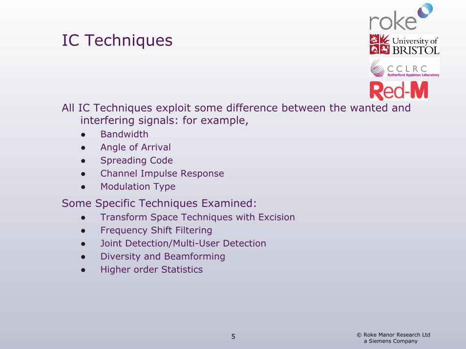
The following Key Applications were considered:
3G overlay on GSM● Ease transition from GSM to 3G. Cancellation of GSM signals in 3G receiver.
GSM to GSM● Ease transition from GSM to 3G. IC option in GSM.
BFWA● IC thought to be required by operators.
Fixed Link to Fixed Link● Potential to reduce large wanted to unwanted ratios.
Radar● Potential for facilitating band sharing.
WLAN● Limited to overcoming ‘hidden terminal problem’.
Broadcast● Improve co-channel re-use in DVB-T/DVB-H.

© Roke Manor Research Ltd a Siemens Company
7
Fixed Links Case Study
Bachir Belloul (Red-M)
© Roke Manor Research Ltd a Siemens Company
8
Introduction
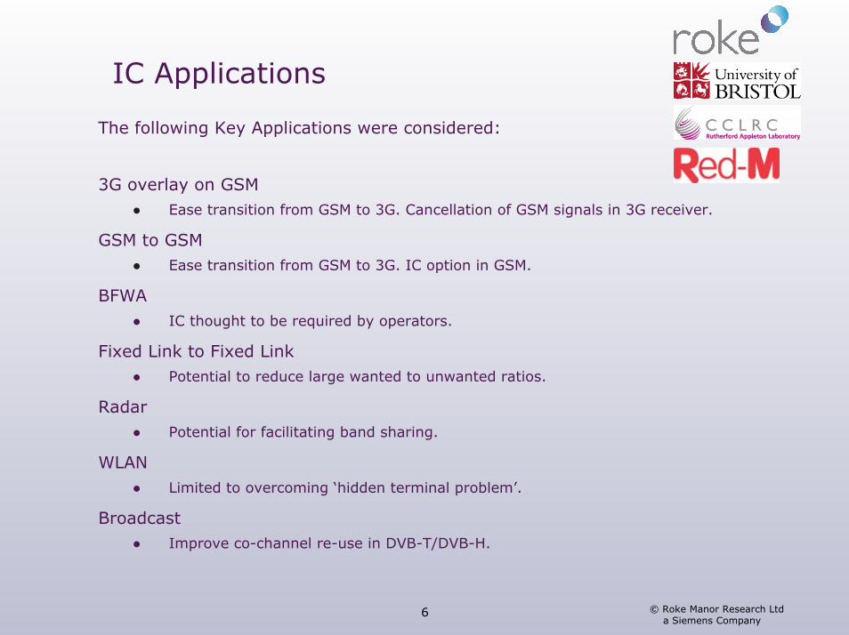
Considered Dual and Single Antenna IC
64-QAM Modulation
Receiver is extension of Decision Feedback Equaliser that:● Handles multiple signals (Joint Detection)● Handles multiple antennas
System Level evaluation based on● Assignment database for 7.5GHz band● Link Level results used to develop simple IC Receiver Model
© Roke Manor Research Ltd a Siemens Company
9
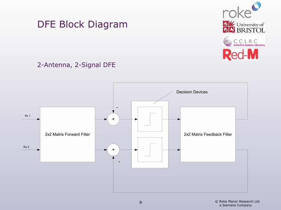
DFE Block Diagram
2-Antenna, 2-Signal DFE
+
+
-
-
2x2 Matrix Forward Filter 2x2 Matrix Feedback Filter
Decision Devices
Rx 1
Rx 2
© Roke Manor Research Ltd a Siemens Company
10
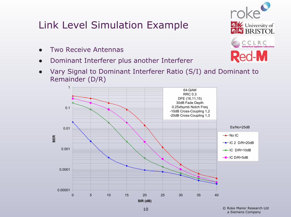
Link Level Simulation Example
● Two Receive Antennas
● Dominant Interferer plus another Interferer
● Vary Signal to Dominant Interferer Ratio (S/I) and Dominant to Remainder (D/R)
0.00001
0.0001
0.001
0.01
0.1
1
0 5 10 15 20 25 30 35 40
SIR (dB)
BER
No IC
IC 2 D/R=20dB
IC D/R=10dB
IC D/R=5dB
64-QAMRRC 0.3
DFE (16,11,15)30dB Fade Depth
0.25xfsymb Notch Freq-10dB Cross-Coupling 1,2-20dB Cross-Coupling 1,3
Es/No=25dB
© Roke Manor Research Ltd a Siemens Company
11
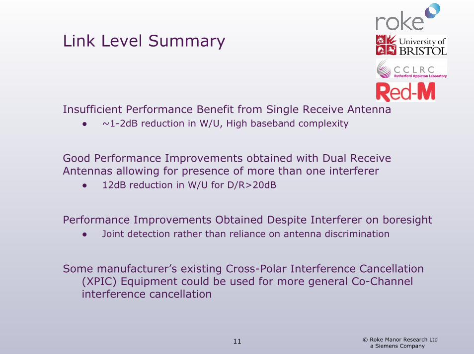
Link Level Summary
Insufficient Performance Benefit from Single Receive Antenna● ~1-2dB reduction in W/U, High baseband complexity
Good Performance Improvements obtained with Dual Receive Antennas allowing for presence of more than one interferer
● 12dB reduction in W/U for D/R>20dB
Performance Improvements Obtained Despite Interferer on boresight● Joint detection rather than reliance on antenna discrimination
Some manufacturer’s existing Cross-Polar Interference Cancellation (XPIC) Equipment could be used for more general Co-Channel interference cancellation
© Roke Manor Research Ltd a Siemens Company
12
System Level Simulation
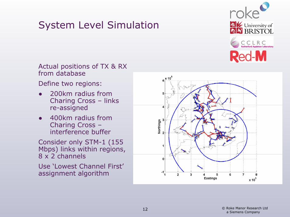
Actual positions of TX & RX from database
Define two regions:
● 200km radius from Charing Cross – links re-assigned
● 400km radius from Charing Cross –interference buffer
Consider only STM-1 (155 Mbps) links within regions, 8 x 2 channels
Use ‘Lowest Channel First’assignment algorithm
© Roke Manor Research Ltd a Siemens Company
13
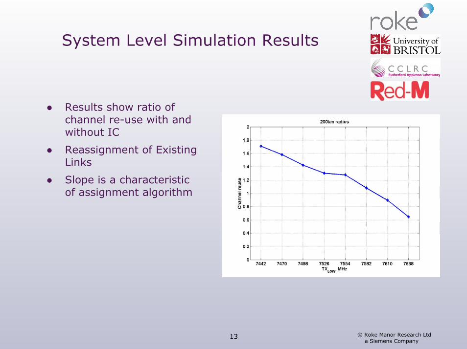
System Level Simulation Results
● Results show ratio of channel re-use with and without IC
● Reassignment of Existing Links
● Slope is a characteristic of assignment algorithm
© Roke Manor Research Ltd a Siemens Company
14
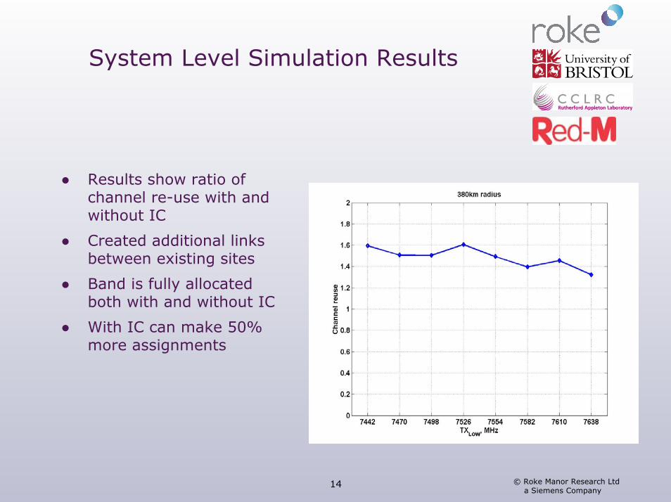
System Level Simulation Results
● Results show ratio of channel re-use with and without IC
● Created additional links between existing sites
● Band is fully allocated both with and without IC
● With IC can make 50% more assignments
© Roke Manor Research Ltd a Siemens Company
15
Cost Analysis
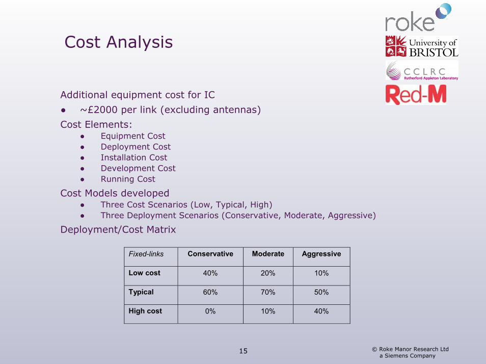
Additional equipment cost for IC
● ~£2000 per link (excluding antennas)
Cost Elements:● Equipment Cost● Deployment Cost● Installation Cost● Development Cost● Running Cost
Cost Models developed● Three Cost Scenarios (Low, Typical, High)● Three Deployment Scenarios (Conservative, Moderate, Aggressive)
Deployment/Cost Matrix
Fixed-links Conservative Moderate Aggressive
Low cost 40% 20% 10%
Typical 60% 70% 50%
High cost 0% 10% 40%
© Roke Manor Research Ltd a Siemens Company
16
Cost Analysis
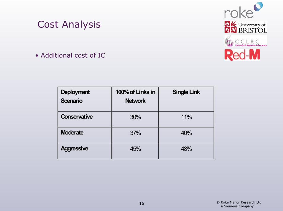
• Additional cost of IC
Deployment Scenario
100% of Links in Network
Single Link
Conservative 30% 11%
Moderate 37% 40%
Aggressive 45% 48%
© Roke Manor Research Ltd a Siemens Company
17
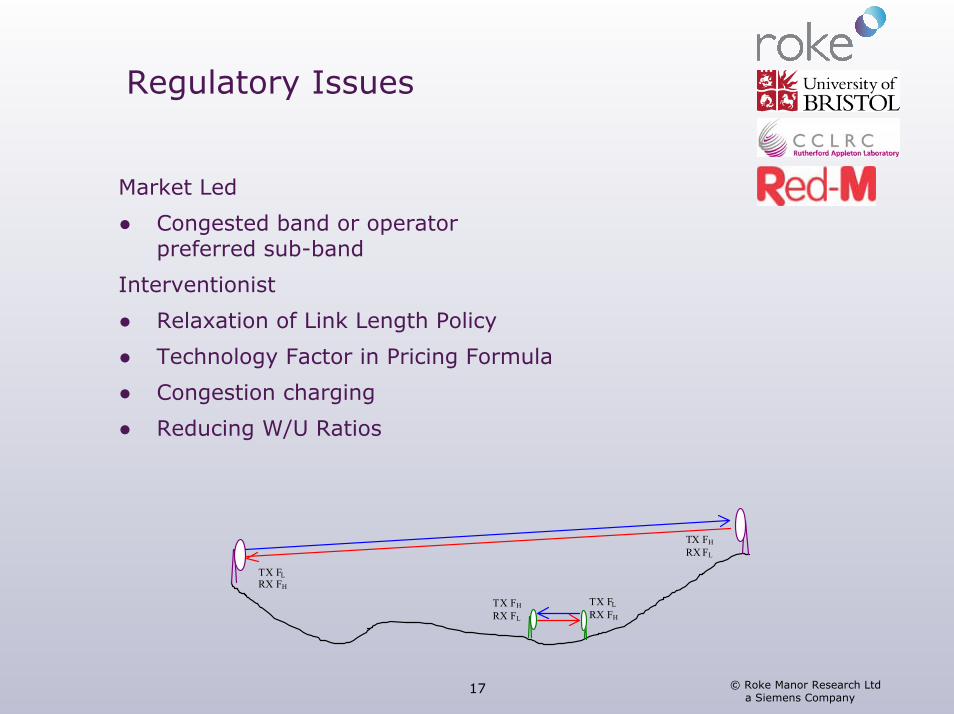
Regulatory Issues
Market Led
● Congested band or operator preferred sub-band
Interventionist
● Relaxation of Link Length Policy
● Technology Factor in Pricing Formula
● Congestion charging
● Reducing W/U Ratios
TX FH RX FL
TX FH RX FL
TX FL RX FH
TX FL RX FH
© Roke Manor Research Ltd a Siemens Company
18
BFWA Case Study
Chris Williams (University of Bristol)
© Roke Manor Research Ltd a Siemens Company
19
Introduction
IEEE 802.16 OFDM Variant for frequencies <11GHz● 256 Carrier OFDM, 5MHz bandwidth, 3.5 GHz Band● BPSK, QPSK, 16-QAM, 64 QAM modulations● Concatenated Reed-Solomon & Convolutional Code● Throughputs 1.73-15.57Mb/s
Single User (SU) and Multi-User (MU) IC Algorithms Studied● Reference Based MMSE Algorithm
Results obtained for 1, 2 & 4 antennas● Omni and Directional Elements
© Roke Manor Research Ltd a Siemens Company
20
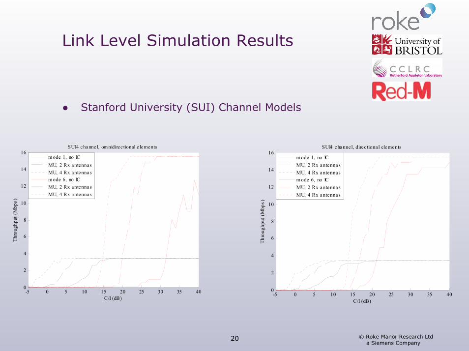
Link Level Simulation Results
● Stanford University (SUI) Channel Models
-5 0 5 10 15 20 25 30 35 400
2
4
6
8
10
12
14
16
C/I (dB)
Thro
ughp
ut (M
bps)
SUI4 channel, om nidirectional e lements
m ode 1, no ICMU, 2 Rx antennasMU, 4 Rx antennasm ode 6, no ICMU, 2 Rx antennasMU, 4 Rx antennas
-5 0 5 10 15 20 25 30 35 400
2
4
6
8
10
12
14
16
C/I (dB)
Thro
ughp
ut (M
bps)
SUI4 channel, directional elements
m ode 1, no ICMU, 2 Rx antennasMU, 4 Rx antennasm ode 6, no ICMU, 2 Rx antennasMU, 4 Rx antennas
© Roke Manor Research Ltd a Siemens Company
21
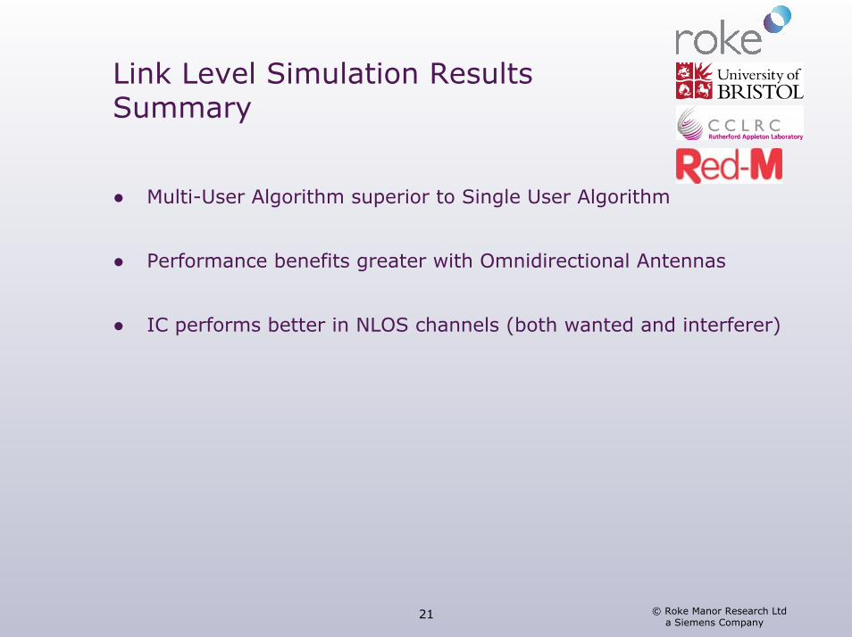
Link Level Simulation Results Summary
● Multi-User Algorithm superior to Single User Algorithm
● Performance benefits greater with Omnidirectional Antennas
● IC performs better in NLOS channels (both wanted and interferer)
© Roke Manor Research Ltd a Siemens Company
22
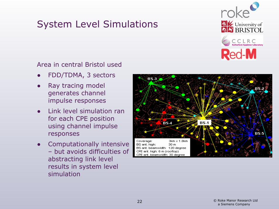
System Level Simulations
Area in central Bristol used
● FDD/TDMA, 3 sectors
● Ray tracing model generates channel impulse responses
● Link level simulation ran for each CPE position using channel impulse responses
● Computationally intensive – but avoids difficulties of abstracting link level results in system level simulation
© Roke Manor Research Ltd a Siemens Company
23
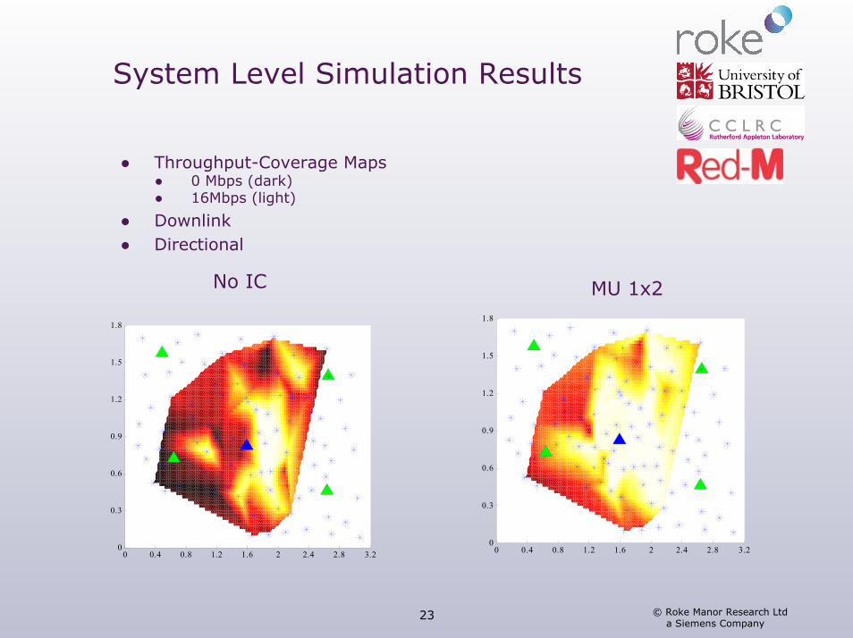
System Level Simulation Results
● Throughput-Coverage Maps ● 0 Mbps (dark)● 16Mbps (light)
● Downlink● Directional
0 0.4 0.8 1.2 1.6 2 2.4 2.8 3.20
0.3
0.6
0.9
1.2
1.5
1.8
0 0.4 0.8 1.2 1.6 2 2.4 2.8 3.20
0.3
0.6
0.9
1.2
1.5
1.8
No IC MU 1x2
© Roke Manor Research Ltd a Siemens Company
24
System Level Simulations Summary
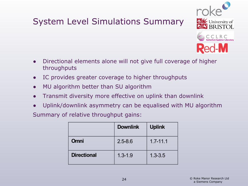
● Directional elements alone will not give full coverage of higherthroughputs
● IC provides greater coverage to higher throughputs
● MU algorithm better than SU algorithm
● Transmit diversity more effective on uplink than downlink
● Uplink/downlink asymmetry can be equalised with MU algorithm
Summary of relative throughput gains:
Downlink Uplink
Omni 2.5-8.6 1.7-11.1
Directional 1.3-1.9 1.3-3.5
© Roke Manor Research Ltd a Siemens Company
25
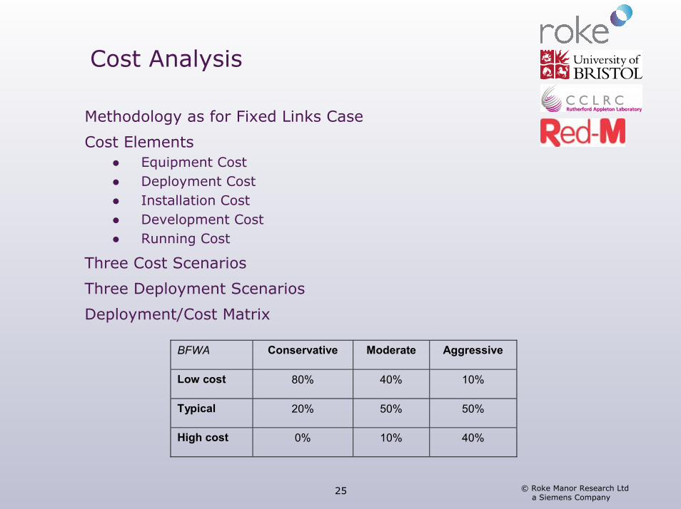
Cost Analysis
Methodology as for Fixed Links Case
Cost Elements● Equipment Cost● Deployment Cost● Installation Cost● Development Cost● Running Cost
Three Cost Scenarios
Three Deployment Scenarios
Deployment/Cost Matrix
BFWA Conservative Moderate Aggressive
Low cost 80% 40% 10%
Typical 20% 50% 50%
High cost 0% 10% 40%
© Roke Manor Research Ltd a Siemens Company
26
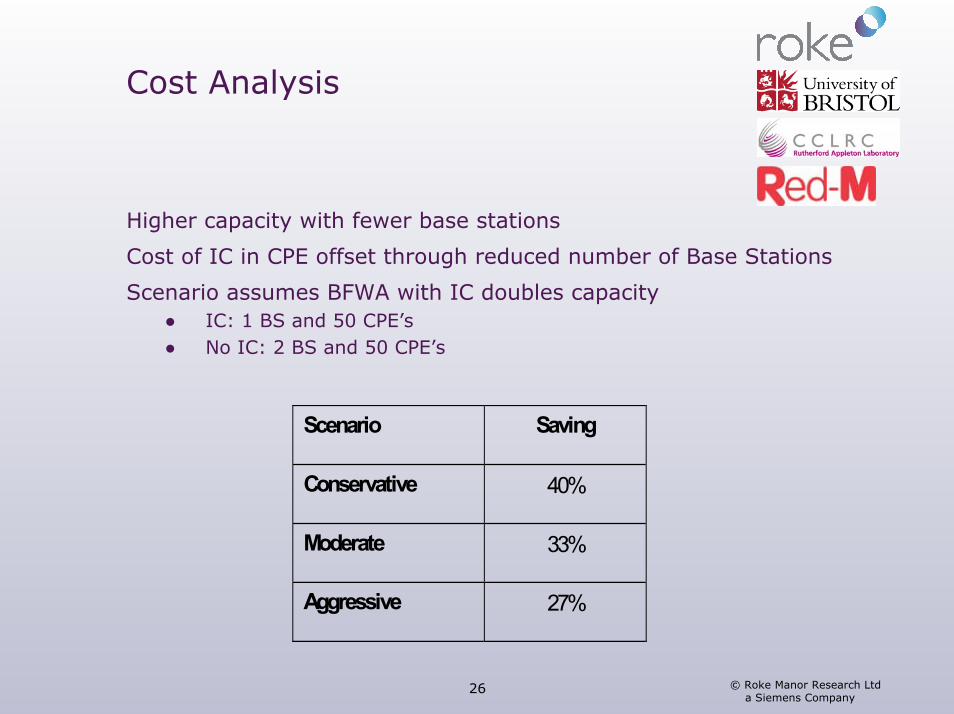
Cost Analysis
Higher capacity with fewer base stations
Cost of IC in CPE offset through reduced number of Base Stations
Scenario assumes BFWA with IC doubles capacity● IC: 1 BS and 50 CPE’s● No IC: 2 BS and 50 CPE’s
Scenario Saving
Conservative 40%
Moderate 33%
Aggressive 27%
© Roke Manor Research Ltd a Siemens Company
27
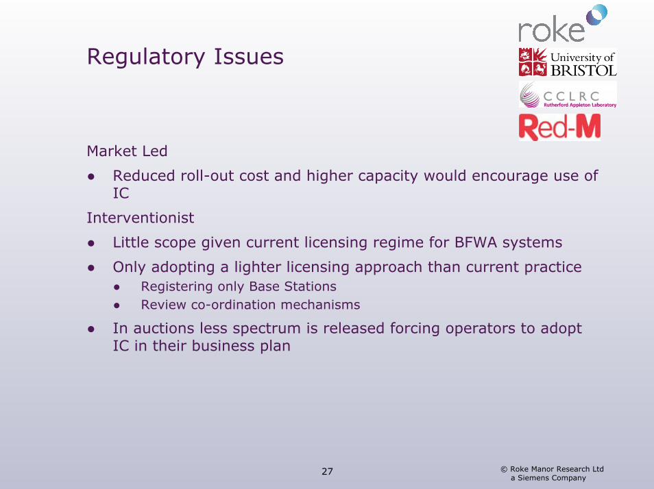
Regulatory Issues
Market Led
● Reduced roll-out cost and higher capacity would encourage use of IC
Interventionist
● Little scope given current licensing regime for BFWA systems
● Only adopting a lighter licensing approach than current practice● Registering only Base Stations● Review co-ordination mechanisms
● In auctions less spectrum is released forcing operators to adoptIC in their business plan

© Roke Manor Research Ltd a Siemens Company
28
Conclusions
Steve Wales (Roke)
© Roke Manor Research Ltd a Siemens Company
29
Fixed Links Conclusions
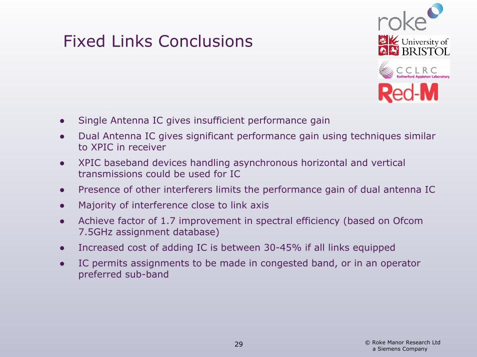
● Single Antenna IC gives insufficient performance gain
● Dual Antenna IC gives significant performance gain using techniques similar to XPIC in receiver
● XPIC baseband devices handling asynchronous horizontal and vertical transmissions could be used for IC
● Presence of other interferers limits the performance gain of dual antenna IC
● Majority of interference close to link axis
● Achieve factor of 1.7 improvement in spectral efficiency (based on Ofcom7.5GHz assignment database)
● Increased cost of adding IC is between 30-45% if all links equipped
● IC permits assignments to be made in congested band, or in an operator preferred sub-band
© Roke Manor Research Ltd a Siemens Company
30
BFWA Conclusions
● Use of directional elements alone cannot provide full sector coverage at high throughput in urban areas
● Largest relative throughput gain found was with the multi-user algorithm and omni-directional antennas
● Throughput gains with IC are reduced with directional antennas● Combination of IC and directional antennas gives best coverage of high
throughputs
● Transmit diversity offers little benefit on downlink, greater benefit on uplink
● For a given installed capacity IC can reduce infrastructure costs by between 27-40%.
© Roke Manor Research Ltd a Siemens Company
31
System Specific Conclusions
Cellular
● Already demonstrated in GSM● Would be most effective in new bands
BFWA
● Cost savings to be had in early roll-out of BFWA in urban areas
Fixed Links
● Allows new assignments to continue in congested bands. Legacy issues will prevent full benefit of IC being realised
Radar
● Potential for IC to improve band sharing. Legacy issues will hinder short-term spectral efficiency gains
Broadcast
● Potential to improve co-channel re-use in DVB-T, DVB-H. Retro-fitting necessary for existing DVB-T systems, but likely to be confined to fringes of coverage.
WLAN
● Protocols used in WLAN applications limit benefits. In WLAN systems with cellular-like infrastructure IC helps to overcome hidden terminal problem
© Roke Manor Research Ltd a Siemens Company
32
General Conclusions
Spectral Efficiency benefits of IC:● Proportional to number of receivers equipped
Maximum benefit from IC:● By applying an existing technology in a new band and mandating IC
New technologies should consider IC to be introduced at some stage in the system lifetime● Ideally defined from the beginning
Market forces could lead to IC adoption in new deployments● Regulatory involvement necessary for existing deployments.

© Roke Manor Research Ltd a Siemens Company
33
Questions and Answers

Contact: Ken RichardsonTel: 01794 833491E-mail: [email protected]
© Roke Manor Research Ltd a Siemens Company
34