Embed Size (px)
Citation preview
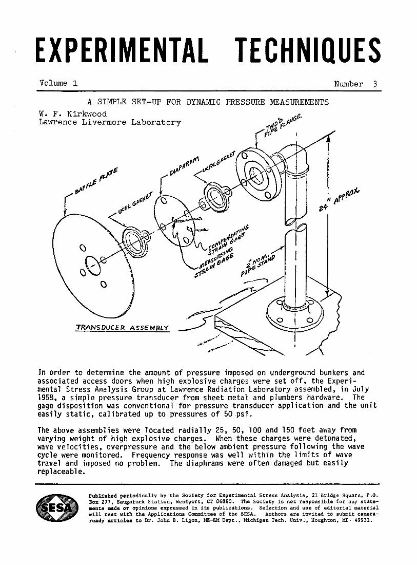
E X P E R I M E NTA 1 T E C H N I Q U E S Volume 1 Number 3
W. La
In order t o determine the amount of pressure imposed on underground bunkers and associated access doors when h i g h explosive charges were s e t o f f , the Experi- mental Stress Analysis Group a t Lawrence Radiation Laboratory assembled, i n July 1958, a simple pressure transducer from sheet metal and plumbers hardware. The gage disposition was conventional f o r pressure transducer application and the u n i t easily s t a t i c , cal ibrated up t o pressures of 50 psi.
The above assemblies were located radial ly 25, 50, I00 and 150 f e e t away from varying weight of h i g h explosive charges. When these charges were detonated, wave veloci t ies , overpressure and the below ambient pressure following the wave cycle were monitored. travel and imposed no problem. replaceable.
Frequency response was well w i t h i n the limits of wave The diaphrams were often damaged b u t eas i ly
Published p e r i o d i c a l l y by t h e Soc ie ty f o r Experimental S t r e s s Analysis , 21 Bridge Square, P.O. Box 277, Saugatuck S t a t i o n , Westport , CT 06880. The Soc ie ty i s no t r e spons ib l e f o r any s t a t e - ments made or opinions expressed i n i t s p u b l i c a t i o n s . S e l e c t i o n and use of e d i t o r i a l material w i l l rest w i t h t h e App l i ca t ions Committee of t h e SESA. Authors are i n v i t e d t o submit camera- ready articles t o D r . John B. Ligon. ME-EM Dept., Michigan Tech. Univ., Houghton, MI. 49931.
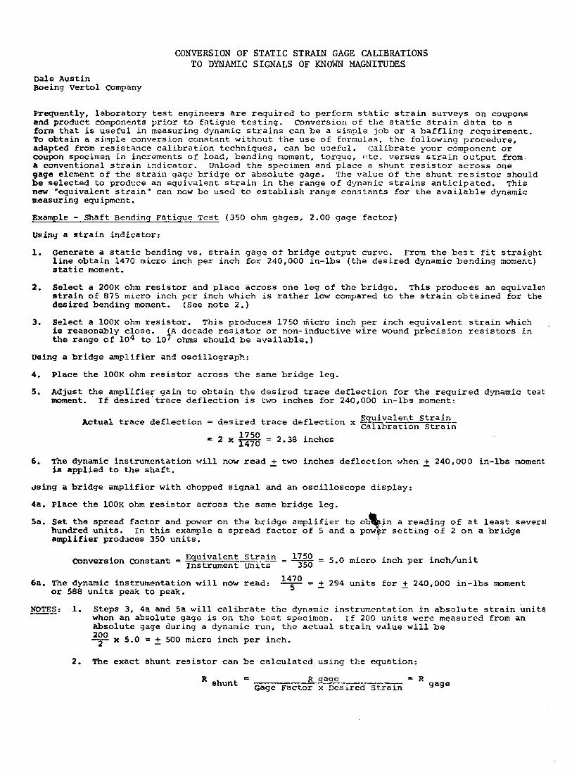
CONVERSION OF STATIC STRAIN GAGE CALIBRATIONS TO DYNAMIC SIGNALS OF KNOWN MAGNITUDES
D a l e Austin Boeing Vertol company
Frequently, l abo ra to ry t e s t engineers are r e q u i r e d t o perform s t a t i c s t r a i n surveys on coupons and product components p r i o r t o f a t i g u e t e s t i n g . Conversion of t h e s t a t i c s t r a i n d a t a t o a form t h a t is use fu l i n measuring dynamic s t r a i n s can be a simple job o r a b a f f l i n g requiremenc. To ob ta in a simple conversion cons t an t w i thou t t h e use of formulas, t h e following proced;lre, adapted from r e s i s t a n c e c a l i b r a t i o n techniques, can be use fu l . c a l i b r a t e your component o r coupon specimen i n increments of load, bending moment, torque, r > t c . versus s t r a i n o u t p u t from a conventional s t r a i n ind ica to r . Unload t h e specimen and. p l ace a shun% r e s i s t o r a c r o s s one gage element o f t h e s t r a i n gage br id3e or abso lu te gage. The value of t h e shunt r e s i s t o r should be se l ec t ed co prodcce an equivalent s t r a i n i n t h e range of dynamic s t r a i n s a n t i c i p a t e d . This new "equivalent s t r a i n " can now be used t o e s t a b l i s h range cons t an t s for t h e a v a i l a b l e dynamic measuring equipment.
Example - s h a f t Bending Fatigue Tes t (350 ohm gages, 2.00 gage f a c t o r )
U s i n y a s t r a i n indicator :
1. Generate a s t a t i c bending vs. s t r a i n gegc of b r i d g e output curve. From t h e best €it s t r a i g h t l i n e o b t a i n 1470 micro inch pe r inch for 240,000 in- lbs ( t h e d e s i r e d dynamic bending aoinent) s ta t ic moment.
2. Se lec t a 200K ohm resistor and p l a c e a c r o s s one leg of t h e br idge. This produces an equivelen s t r a i n o f 875 micro inch pe r inch which is rather low compared to t h e s t r a i n o b t a i n e d f o r the des i r ed bending moment. (See note 2 . )
3. S e l e c t a l O O K ohm r e s i s t o r . This prhduces 1750 riiicro inch p e r inch equ iva len t s t r a i n which is reasonably c lose . A decade r e s i s t o r o r non-inductive w i r e wound pr 'ecis ion r e s i s t o r s i n t h e range o f l o 4 t o 10 4 ohms should be ava i l ab le . )
Using a b r idge ampl i f i e r and osc i l l og raph :
4. Place t h e l O O K ohm r e s i s t o r ac ross t h e same b r i d g e l eg .
5 . Adjust t h e ampl ' if ier ga in to o b t a i n t h e d e s i r e d t r a c e d e f l e c t i o n f o r t h e r e q u i r e d dynamic t e s t mment. I f des i r ed trace d e f l e c t i o n i s t w o inches f o r 240,000 i n - lb s moment:
Eauivalent S t r a in - Actual trace d e f l e c t i o n = d e s i r e d trace d e f l e c t i o n x G~~~~~~~~ Strain 1750 1470 = 2 x - = 2.38 inches
6. The dynamic instrumentation w i l l now r e a d 2 two inches d e f l e c t i o n when f 240,000 in-lbs moment is appl ied t o t h e s h a f t .
J s i n g a b r idge amplif ier w i th chopped s i g n a l and an osc i l l o scope d i sp lay :
4a. Place t h e l O O K ohm r e s i s t o r ac ross t h e s a m e b r i d g e l eg .
Sa. S e t t h e spread f a c t o r and power on t h e b r i d g e ampl i f i e r t o ob$in a r ead ing of a t l e a s t several hundred u n i t s . In t h i s example a sp read f a c t o r of 5 and a power s e t t i n g of 2 o n a b r i d g e ampl i f i e r produces 350 u n i t s .
6a. The dynamic instrumentation w i l l now read: - 14i0 - - - + 294 u n i t s f o r f 240,000 i n - l b s moment or 588 u n i t s peak t o peak.
NOTES: 1. Steps 3, 4a and 5a w i l l c a l i b r a t e t h e dynamic instrumentat ion i n a b s o l u t e s t r a i n u n i t s when an absolute gage is 011 t h e t es t specimen. If 200 u n i t s w e r e measured from an abso lu te gage during a dynamic run, t h e a c t u a l s t r a i n value w i l l be - 2oo x 5.0 = 2 500 micro inch per inch.
2
2. The exact shunt r e s i s t o r can be c a l c u l a t e d using t h e equation:
= R gage = R shunt Gage Factor x Desired S t r a i n gage