Embed Size (px)
Citation preview

1
A Scalable and Resilient Layer-2 Network withEthernet Compatibility
Chen Qian, Member, IEEE, and Simon S. Lam, Fellow, IEEE
Abstract—We present the architecture and protocols of ROME,a layer-2 network designed to be backwards compatible withEthernet and scalable to tens of thousands of switches andmillions of end hosts. Such large-scale networks are neededfor emerging applications including data center networks, widearea networks, and metro Ethernet. ROME is based upona recently developed greedy routing protocol, greedy distancevector (GDV). Protocol design innovations in ROME includea stateless multicast protocol, a Delaunay DHT, as well asrouting and host discovery protocols for a hierarchical network.ROME protocols do not use broadcast and provide both control-plane and data-plane scalability. Extensive experimental resultsfrom a packet-level event-driven simulator, in which ROMEprotocols are implemented in detail, show that ROME protocolsare efficient and scalable to metropolitan size. Furthermore,ROME protocols are highly resilient to network dynamics. Therouting latency of ROME is only slightly higher than shortest-path latency. To demonstrate scalability, we provide simulationperformance results for ROME networks with up to 25,000switches and 1.25 million hosts.
I. INTRODUCTION
Layer-2 networks, each scalable to tens of thousands ofswitches/routers and connecting millions of end hosts, areneeded for important future and current applications andservices including: data center networks [14], metro Ethernet[1], [4], [15], [17], wide area networks [5], [19], [16], as wellas enterprise and provider networks.
Ethernet offers plug-and-play functionality and a flat MACaddress space. Ethernet MAC addresses, being permanentand location independent, support host mobility and facilitatemanagement functions, such as trouble shooting and accesscontrol. For these reasons, Ethernet is easy to manage. How-ever Ethernet is not scalable to a large network because it usesa spanning tree routing protocol that is highly inefficient andnot resilient to failures. Also, after a cache miss, it relies onnetwork-wide flooding for host discovery and packet delivery.
Today’s metropolitan and wide area Ethernet services pro-vided by network operators are based upon a network ofIP (layer-3) and MPLS routers which interconnect relativelysmall Ethernet LANs [15]. Adding the IP layer to performend-to-end routing in these networks nullifies Ethernet’s de-sirable properties. Large IP networks require massive effortsby human operators to configure and manage, especially forenterprise and data center networks where host mobility andVM migration are ubiquitous. This is because IP addresses
This work was sponsored by National Science Foundation grants CNS-0830939 and CNS-1214239. An abbreviated version of this paper [38]appeared in Proceedings of IEEE ICNP, Austin, TX, November 2012.
Chen Qian is with the Department of Computer Science, University ofKentucky, Lexington, KY 40506 (e-mail: [email protected]). Simon S. Lam iswith the Department of Computer Science, The University of Texas at Austin,Austin, TX 78712 (e-mail: [email protected]).
are location-dependent and change with host mobility and VMmigration. Network configurations and policies, such as accesscontrol policies, specified by IP addresses require frequentupdates which impose a large administrative burden. As anexample, Google’s globally-distributed database scales up tomillions of machines across hundreds of data centers [10]which are interconnected in layer 3. Using a scalable layer-2networking technology, management complexity and cost ofsuch huge networks could be significantly reduced.
Networks that use shortest-path routing on flat addressing inlayer 2 have been proposed [21], [14]. These networks requirea large amount of data-plane state (forwarding table entries) toreach every destination in the network. Also, when multicastand VLAN are used, each switch has to store a lot more stateinformation. Such data plane scalability is challenging becausehigh-speed memory is both expensive and power hungry [49].
Besides scalability, resiliency is also an important require-ment of large layer-2 networks. According to a recent studyby Cisco [3], availability and resilience are the most importantnetwork performance metrics for distributed data processing,such as Hadoop, in large data centers. Without effective fail-ure recovery techniques, job completion will be significantlydelayed.
Therefore, it is desirable to have a scalable and resilientlayer-2 network that is backwards compatible with Ether-net, i.e., its switches interact with hosts by Ethernet framesusing conventional Ethernet format and semantics. Ethernetcompatibility provides plug-and-play functionality and ease ofnetwork management. Hosts still run current protocols and useIP addresses as identifiers but the network does not use IPaddresses for routing.
In this paper, we present the architecture and protocols of ascalable and resilient layer-2 network, named ROME (which isacronym for Routing On Metropolitan-scale Ethernet). ROMEis fully decentralized and self-organizing without any centralcontroller or special nodes. All switches execute the samedistributed algorithms in the control plane. ROME uses greedyrouting instead of spanning-tree or shortest-path routing toachieve scalability and resiliency. ROME provides control-plane scalability by eliminating network broadcast and limitingcontrol message propagation within a local area. ROME pro-vides data-plane scalability because each switch stores smallrouting and multicast states.
ROME protocols utilize some recent advances in greedyrouting, namely, GDV on VPoD [37] and MDT [25]. Un-like greedy routing in wireless sensor and ad hoc networks,switches in ROME do not need any location information.For routing in ROME, a virtual space is first specified, such
2
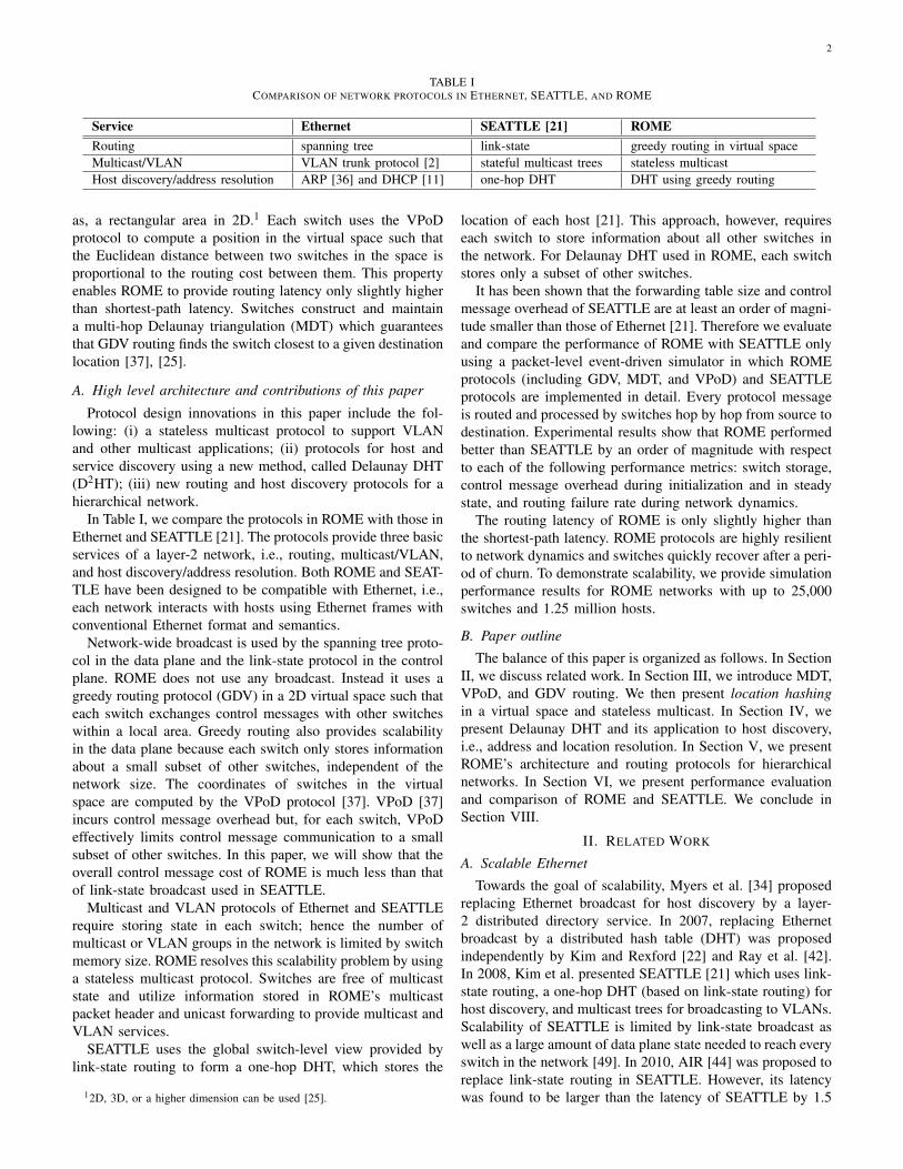
TABLE ICOMPARISON OF NETWORK PROTOCOLS IN ETHERNET, SEATTLE, AND ROME
Service Ethernet SEATTLE [21] ROMERouting spanning tree link-state greedy routing in virtual spaceMulticast/VLAN VLAN trunk protocol [2] stateful multicast trees stateless multicastHost discovery/address resolution ARP [36] and DHCP [11] one-hop DHT DHT using greedy routing
as, a rectangular area in 2D.1 Each switch uses the VPoDprotocol to compute a position in the virtual space such thatthe Euclidean distance between two switches in the space isproportional to the routing cost between them. This propertyenables ROME to provide routing latency only slightly higherthan shortest-path latency. Switches construct and maintaina multi-hop Delaunay triangulation (MDT) which guaranteesthat GDV routing finds the switch closest to a given destinationlocation [37], [25].
A. High level architecture and contributions of this paper
Protocol design innovations in this paper include the fol-lowing: (i) a stateless multicast protocol to support VLANand other multicast applications; (ii) protocols for host andservice discovery using a new method, called Delaunay DHT(D2HT); (iii) new routing and host discovery protocols for ahierarchical network.
In Table I, we compare the protocols in ROME with those inEthernet and SEATTLE [21]. The protocols provide three basicservices of a layer-2 network, i.e., routing, multicast/VLAN,and host discovery/address resolution. Both ROME and SEAT-TLE have been designed to be compatible with Ethernet, i.e.,each network interacts with hosts using Ethernet frames withconventional Ethernet format and semantics.
Network-wide broadcast is used by the spanning tree proto-col in the data plane and the link-state protocol in the controlplane. ROME does not use any broadcast. Instead it uses agreedy routing protocol (GDV) in a 2D virtual space such thateach switch exchanges control messages with other switcheswithin a local area. Greedy routing also provides scalabilityin the data plane because each switch only stores informationabout a small subset of other switches, independent of thenetwork size. The coordinates of switches in the virtualspace are computed by the VPoD protocol [37]. VPoD [37]incurs control message overhead but, for each switch, VPoDeffectively limits control message communication to a smallsubset of other switches. In this paper, we will show that theoverall control message cost of ROME is much less than thatof link-state broadcast used in SEATTLE.
Multicast and VLAN protocols of Ethernet and SEATTLErequire storing state in each switch; hence the number ofmulticast or VLAN groups in the network is limited by switchmemory size. ROME resolves this scalability problem by usinga stateless multicast protocol. Switches are free of multicaststate and utilize information stored in ROME’s multicastpacket header and unicast forwarding to provide multicast andVLAN services.
SEATTLE uses the global switch-level view provided bylink-state routing to form a one-hop DHT, which stores the
12D, 3D, or a higher dimension can be used [25].
location of each host [21]. This approach, however, requireseach switch to store information about all other switches inthe network. For Delaunay DHT used in ROME, each switchstores only a subset of other switches.
It has been shown that the forwarding table size and controlmessage overhead of SEATTLE are at least an order of magni-tude smaller than those of Ethernet [21]. Therefore we evaluateand compare the performance of ROME with SEATTLE onlyusing a packet-level event-driven simulator in which ROMEprotocols (including GDV, MDT, and VPoD) and SEATTLEprotocols are implemented in detail. Every protocol messageis routed and processed by switches hop by hop from source todestination. Experimental results show that ROME performedbetter than SEATTLE by an order of magnitude with respectto each of the following performance metrics: switch storage,control message overhead during initialization and in steadystate, and routing failure rate during network dynamics.
The routing latency of ROME is only slightly higher thanthe shortest-path latency. ROME protocols are highly resilientto network dynamics and switches quickly recover after a peri-od of churn. To demonstrate scalability, we provide simulationperformance results for ROME networks with up to 25,000switches and 1.25 million hosts.
B. Paper outline
The balance of this paper is organized as follows. In SectionII, we discuss related work. In Section III, we introduce MDT,VPoD, and GDV routing. We then present location hashingin a virtual space and stateless multicast. In Section IV, wepresent Delaunay DHT and its application to host discovery,i.e., address and location resolution. In Section V, we presentROME’s architecture and routing protocols for hierarchicalnetworks. In Section VI, we present performance evaluationand comparison of ROME and SEATTLE. We conclude inSection VIII.
II. RELATED WORK
A. Scalable Ethernet
Towards the goal of scalability, Myers et al. [34] proposedreplacing Ethernet broadcast for host discovery by a layer-2 distributed directory service. In 2007, replacing Ethernetbroadcast by a distributed hash table (DHT) was proposedindependently by Kim and Rexford [22] and Ray et al. [42].In 2008, Kim et al. presented SEATTLE [21] which uses link-state routing, a one-hop DHT (based on link-state routing) forhost discovery, and multicast trees for broadcasting to VLANs.Scalability of SEATTLE is limited by link-state broadcast aswell as a large amount of data plane state needed to reach everyswitch in the network [49]. In 2010, AIR [44] was proposed toreplace link-state routing in SEATTLE. However, its latencywas found to be larger than the latency of SEATTLE by 1.5
3
orders of magnitude. In 2011, VIRO [18] was proposed toreplace link-state routing. To construct a rooted virtual binarytree for routing, a centralized algorithm was used for largenetworks (e.g., enterprise and campus networks).
To increase the throughput and scalability of Ethernet fordata center networks, SPAIN [33] and PAST [46] proposed theuse of many spanning trees for routing. In SPAIN, an offlinenetwork controller first pre-computes a set of paths that exploitredundancy in a given network topology. The controller thenmerges these paths into a set of trees and maps each treeonto a separate VLAN. SPAIN requires modification to endhosts. PAST does not requires end-host modification; instead,a spanning tree is installed in network switches for every host.The important issue of data plane scalability was not addressedin both papers.
In four of the five papers with simulation results to shownetwork performance [21], [44], [18], [46], scalability wasdemonstrated for networks of several hundred switches. InSPAIN [33], simulation experiments were performed for spe-cial data center network topologies (e.g., Fat Tree) of up to2,880 switches. In this paper, we demonstrate scalability ofROME from experiments that ran on a packet-level event-driven simulator for up to 25,000 switches and 1.25 millionhosts.
ROME was designed to run on general topologies. Today’sdata center networks are often physically inter-connected asa multi-rooted tree. Thus special topologies with a knownstructure can be exploited to improve routing and forwardingefficiency. FCP [24] shows the benefits of assuming someknowledge of baseline topology in routing protocols. PortLand[35] is a scalable layer-two design for Fat Tree topologies. Itemploys a lightweight protocol to enable switches to discovertheir positions in the topology. It further assigns internalhierarchical addresses to all end hosts to encode their positionsin the topology. Portland uses a central controller to handle themore complicated portions of address assignment as well asall routing. ALIAS was later designed to explore the extentto which hierarchical host labels can be assigned for routingand forwarding, in a decentralized, scalable, and broadcast-free manner for indirect hierarchical topologies [48].
B. Greedy routing and virtual coordinates
Many greedy geographic routing protocols have been de-signed for wireless sensor and ad hoc networks. Two of theearliest protocols, GFG [8] and GPSR [20], use face routing tomove packets out of local minima. They require the networktopology to be a planar graph in 2D to avoid routing failures.Kim et al. [23] proposed CLDP which, given any connectivitygraph, produces a subgraph in which face routing would notcause routing failures. Leong et al. proposed GDSTR [27]for greedy routing without the planar graph assumption bymaintaining a hull tree. Lam and Qian proposed MDT [25]for any connectivity graph of nodes with arbitrary coordinatesin a d-dimensional Euclidean space (d ≥ 2). From simulationexperiments in which GFG/GPSR, CLDP, GDSTR, and MDT-greedy ran on the same networks, it is shown that MDT-greedyprovides the lowest routing stretch and the highest routingsuccess rate (1.0) [25].
Many virtual coordinate schemes have been proposed forwireless networks when node location information is un-available (e.g., [39], [12], and [9]). In each scheme, themain objective is to improve greedy routing success rate.Tsuchiya designed a hierarchical routing protocol using virtuallandmarks for large networks [47]. Lua et al. proposed to usenetwork-aware coordinates for overlay multicast [28]. VPoD[37] is the only virtual coordinate protocol designed to predictand minimize the routing cost between nodes.
III. ROUTING IN ROME
A. Services provided by MDT, VPoD, and GDV
ROME uses greedy routing to provide scalability and re-siliency. The protocol used by ROME switches is GDV routingwhich uses services provided by VPoD and MDT protocols[37], [25].
In what follows, we first define Delaunay triangulation (DT)before providing a brief overview of the three protocols.
A triangulation of a set S of nodes (points) in 2D isa subdivision of the convex hull of nodes in S into non-overlapping triangles such that the vertices of each triangleare nodes in S. A DT in 2D is a triangulation such thatthe circumcircle of each triangle does not contain any othernode inside [13]. The definition of DT can be generalizedto a higher dimensional Euclidean space using simplexes andcircum-hyperspheres. In each case, the DT of S is a graph thatcan be computed from locations of the nodes in the Euclideanspace.
In a DT, two nodes sharing an edge are said to be DTneighbors. For 2D, Bose and Morin [7] proved that greedyforwarding in a DT guarantees to find the destination node.For 2D, 3D, and higher dimensional Euclidean spaces, Leeand Lam [26] generalized their result and proved that greedyforwarding in a DT guarantees to find the node closest to adestination location. Since two neighbors in a DT graph maynot be directly-connected, nodes maintain forwarding tablesfor communication between DT neighbors multiple hops apart(hence the name, multi-hop DT [25]).
At network initialization, each ROME switch assigns itself arandom location in the virtual space and discovers its directly-connected neighbors. Each pair of directly-connected switchesexchange their unique identifiers (e.g., MAC addresses) andself-assigned locations. Then, the switches have enough in-formation to construct and maintain a multi-hop Delaunaytriangulation using MDT protocols [25].
ROME switches then repeatedly exchange messages withtheir neighbors, including multi-hop DT neighbors, and changetheir positions. Using the VPoD protocol [37], each switchmoves its location in the virtual space by comparing, for eachneighbor, the Euclidean distance with the routing cost betweenthem. (Routing cost can be in any additive metric.) A switchstops running VPoD when the amount of location change hasconverged to less than a threshold value. When all switchesfinish, the Euclidean distance between two switches in thevirtual space approximates the routing cost between them.(This is why greedy routing using VPoD coordinates can findnear-optimal routes.) Then switches use their updated locations
4
to construct a new multi-hop DT to be used by GDV routing[37].
GDV routing is greedy routing in the multi-hop DT of aset of nodes with VPoD coordinates [37]. GDV guarantees toroute every packet to the switch that is closest to the packet’sdestination location. It has been shown that the VPoD protocolis very effective such that GDV’s routing cost is not muchhigher than that of shortest-path routing.
MDT [25] and VPOD [37] protocols do not use broadcast.MDT has a very efficient and effective search method foreach switch to find its multi-hop DT neighbors; in particular,each switch only communicates with a small subset of otherswitches in a large network. Also, construction of virtualcoordinates by VPoD can be performed in a short time.Furthermore, MDT and VPoD protocols have been designedto be highly resilient to rapid topology changes. Due to spacelimitation, we omit a detailed explanation of design tradeoffsand performance evaluation results of MDT, VPoD, and GDV.The interested reader is referred to our prior publications [25],[37].
B. Virtual space for switches
Consider a network of switches with an arbitrary topology(any connected graph). Each switch selects one of its MAC ad-dresses to be its identifier. End hosts are connected to switcheswhich provide frame delivery between hosts. Ethernet framesfor delivery are encapsulated in ROME packets. Switchesinteract with hosts by Ethernet frames using conventionalEthernet format and semantics. ROME protocols run only inswitches. Link-level delivery is assumed to be reliable.
A Euclidean space (2D, 3D, or a higher dimension) ischosen as the virtual space. The number of dimensions andthe minimum and maximum coordinate values of each di-mension are specified in the token at the beginning of VPoDconstruction [37] and known to all switches. Each switchdetermines for itself a location in the space represented bya set of coordinates.
Location hashing. To start ROME protocols, each switchboots up and assigns itself an initial location randomly byhashing its identifier, IDS, using a globally-known hash func-tion H. The hash value is a binary number which is convertedto a set of coordinates. Our protocol implementation uses thehash function MD5 [43], which outputs a 16-byte binary value.4 bytes are used for each dimension. Thus locations can be in2D, 3D, or 4D.2
Consider, for example, a network that uses a 2D virtualspace. For 2D, the last 8 bytes of H(IDS) are converted to two4-byte binary numbers, x and y. Let MAX be the maximum4-byte binary value, that is, 232 − 1. Also let mink and maxkbe the minimum and maximum coordinate values for the kthdimension. Then the location in 2D obtained from the hash val-ue is (min1 +
xMAX (max1 −min1), min2 +
yMAX (max2 −min2)),
where each coordinate is a real number. The location can bestored in decimal format, using 4 bytes per dimension. Here-after, for any identifier, ID, we will use H(ID) to represent
2Conceptually, a higher dimensional space gives VPoD more flexibility butrequires more storage space and control overhead. Our experimental resultsshow that VPoD’s performance in 2D is already very good.
its location in the virtual space and refer to H(ID) as theidentifier’s location hash or, simply, location.
Switches discover their directly-connected neighbors and,using their initial locations, proceed to construct a multi-hopDT [25]. Switches then update their locations using VPoDand construct a new multi-hop DT as described in subsectionIII-A.
Unicast routing. Unicast packet delivery in ROME isprovided by GDV routing in the multi-hop DT maintained byswitches. In a correct multi-hop DT, GDV routing of a packetguarantees to find the switch that is closest to the destinationlocation of the packet [25], [37] assuming reliable link-leveldelivery and no packet drop due to congestion.
As in most prior work [21], [49], [44], [18], the issue ofmulti-path routing and traffic engineering is not addressedherein and will be an interesting problem for future work.
C. Hosts
Hosts have IP and MAC addresses. Each host is directlyconnected to a switch called its access switch. An accessswitch knows the IP and MAC addresses of every hostconnected to it. The routable address of each host is thelocation of its access switch in the virtual space, also called thehost’s location. Hosts are not aware of ROME protocols andrun ARP [36], DHCP [11], and Ethernet protocols in the sameway as when they are connected to a conventional Ethernet.
D. Stateless multicast and its applications
To provide the same services as conventional Ethernet,ROME needs to support group-wide broadcast or multicast,for applications, such as, VLAN, teleconferencing, television,replicated storage/update in data centers, etc.
A straightforward way to deliver messages to a groupis by using a multicast tree similar to IP multicast [21].All broadcast packets within a group are delivered througha multicast tree sourced at a dedicated switch, namely abroadcast root, of the group. When a switch detects that one ofits hosts is a member of a group, the switch joins the group’smulticast tree and stores some multicast state for this group.When there are many groups with many hosts in each group,the amount of multicast state stored in switches can becomea scalability problem.
We present a stateless multicast protocol for group-widebroadcast in ROME. A group message is delivered using thelocations of its receivers without construction of any multicasttree. Switches do not store any state for delivering groupmessages.
The membership information of stateless multicast is main-tained at a rendezvous point (RP) for each group. The RP ofa group is determined by the location hash H(IDG), whereIDG is the group’s ID. The switch whose location is closestto H(IDG) serves as the group’s RP. The access switch of thesender of a group message sends the message to the RP byunicast. GDV routing guarantees to find the switch closest toH(IDG).
The RP then forwards the message to other group members(receivers) as follows: The RP partitions the entire virtualspace into multiple regions. To each region with one or more
5
SP1
S1
S2
S3
a
b
c
d f
e
g
(a) Split at S1
SP1
SP2
S1
S2 S3
a
b
c
d f
e
g
(b) Splits at S2 and S3
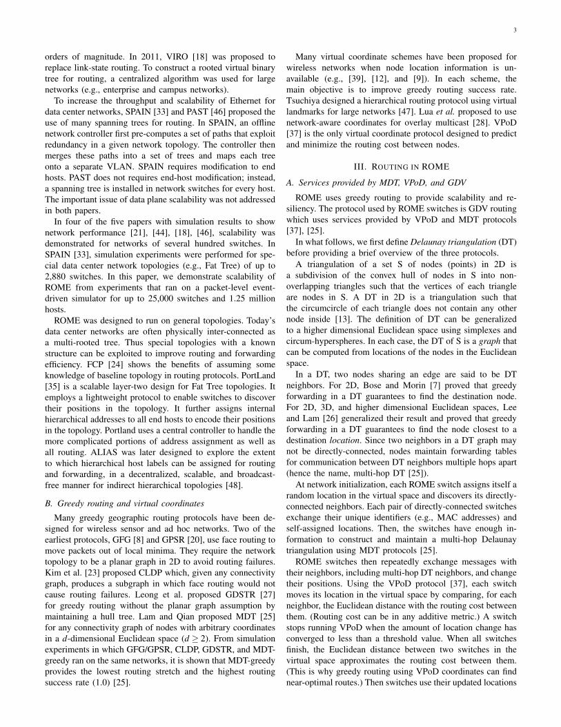
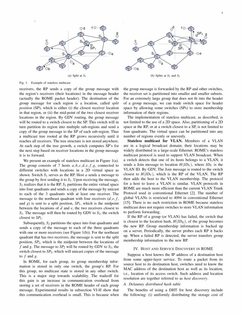
Fig. 1. Example of stateless multicast
receivers, the RP sends a copy of the group message withthe region’s receivers (their locations) in the message header(actually the ROME packet header). The destination of thegroup message for each region is a location, called splitposition (SP), which is either (i) the closest receiver locationin that region, or (ii) the mid-point of the two closest receiverlocations in the region. By GDV routing, the group messagewill be routed to a switch closest to the SP. This switch will inturn partition its region into multiple sub-regions and send acopy of the group message to the SP of each sub-region. Thusa multicast tree rooted at the RP grows recursively until itreaches all receivers. The tree structure is not stored anywhere.At each step of the tree growth, a switch computes SP’s forthe next step based on receiver locations in the group messageit is to forward.
We present an example of stateless multicast in Figure 1(a).The group consists of 7 hosts a,b,c,d,e, f ,g, connected todifferent switches with locations in a 2D virtual space asshown. Switch S1 serves as the RP. Host a sends a message tothe group by first sending it to S1. Upon receiving the message,S1 realizes that it is the RP. S1 partitions the entire virtual spaceinto four quadrants and sends a copy of the message by unicastto each of the 3 quadrants with at least one receiver. Themessage to the northeast quadrant with four receivers (d,e, f ,and g) is sent to a split position, SP1, which is the midpointbetween the locations of d and e, the two receivers closest toS1. The message will then be routed by GDV to S2, the switchclosest to SP1.
Subsequently, S2 partitions the space into four quadrants andsends a copy of the message to each of the three quadrantswith one or more receivers (see Figure 1(b)). For the northeastquadrant that has two receivers, the message is sent to the splitposition, SP2, which is the midpoint between the locations off and g. The message to SP2 will be routed by GDV to S3, theswitch closest to SP2, which will unicast copies of the messageto f and g.
In ROME, for each group, its group membership infor-mation is stored in only one switch, the group’s RP. Forthis group, no multicast state is stored in any other switch.This is a major step towards scalability. The tradeoff forthis gain is an increase in communication overhead fromstoring a set of receivers in the ROME header of each groupmessage. Experimental results in subsection VI-H show thatthis communication overhead is small. This is because when
the group message is forwarded by the RP and other switches,the receiver set is partitioned into smaller and smaller subsets.For an extremely large group that does not fit into the headerof a group message, we can trade switch space for headerspace by allowing some switches (SPs) to store membershipinformation of their regions.
The implementation of stateless multicast, as described, isnot limited to the use of a 2D space. Also, partitioning of a 2Dspace at the RP, or at a switch closest to a SP, is not limited tofour quadrants. The virtual space can be partitioned into anynumber of regions evenly or unevenly.
Stateless multicast for VLAN. Members of a VLANare in a logical broadcast domain; their locations may bewidely distributed in a large-scale Ethernet. ROME’s statelessmulticast protocol is used to support VLAN broadcast. Whena switch detects that one of its hosts belongs to a VLAN, itsends a Join message to location H(IDV ), where IDV is theVLAN ID. By GDV, The Join message is routed to the switchclosest to H(IDV ), which is the RP of the VLAN. The RPthen adds the host to the VLAN membership. The protocolfor a host to leave a VLAN is similar. VLAN protocols inROME are much more efficient than the current VLAN TrunkProtocol used in conventional Ethernet [2]. The number ofglobal VLANs is restricted to 4094 in conventional Ethernet[15]. There is no such restriction in ROME because statelessmulticast does not require switches to store VLAN informationto perform forwarding.
If the RP of a group (or VLAN) has failed, the switch thatis closest to the location hash, H(IDG), of the group becomesthe new RP. Group membership information is backed upon a server. Periodically, the server probes each RP it backsup. When a failed RP is detected, the server transfers groupmembership information to the new RP.
IV. HOST AND SERVICE DISCOVERY IN ROMESuppose a host knows the IP address of a destination host
from some upper-layer service. To route a packet from itssource host to its destination host, switches need to know theMAC address of the destination host as well as its location,i.e., location of its access switch. Such address and locationresolution are together referred to as host discovery.A. Delaunay distributed hash table
The benefits of using a DHT for host discovery includethe following: (i) uniformly distributing the storage cost of
6
Location
H(kb)
Sa
2. S’: closest to
H(kb), stores
the tuple
Sb
a
b
3. Message to b
4. Sending the
query to H(kb)
1. Publishing <kb, vb>
to H(kb)
5. Replying <kb, vb>
to Sa
S’
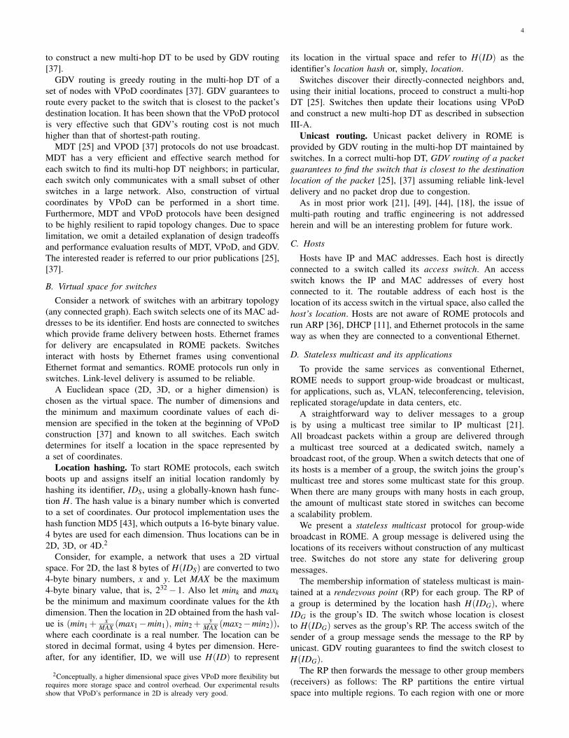
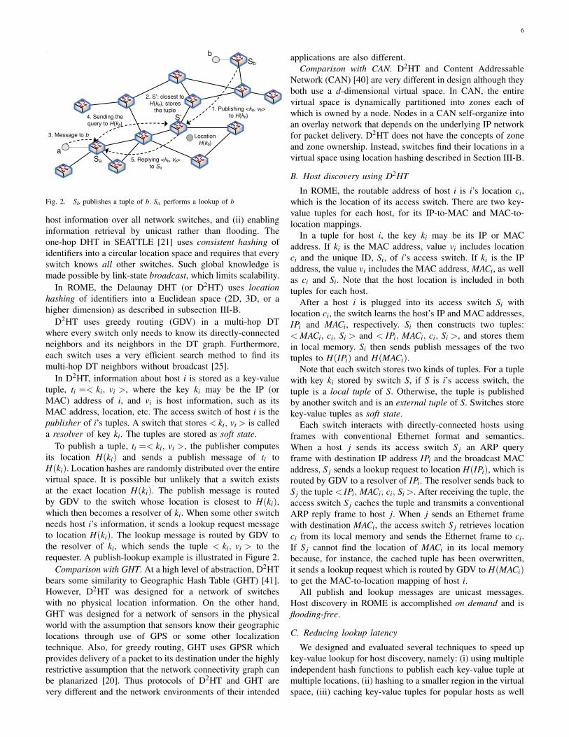
Fig. 2. Sb publishes a tuple of b. Sa performs a lookup of b
host information over all network switches, and (ii) enablinginformation retrieval by unicast rather than flooding. Theone-hop DHT in SEATTLE [21] uses consistent hashing ofidentifiers into a circular location space and requires that everyswitch knows all other switches. Such global knowledge ismade possible by link-state broadcast, which limits scalability.
In ROME, the Delaunay DHT (or D2HT) uses locationhashing of identifiers into a Euclidean space (2D, 3D, or ahigher dimension) as described in subsection III-B.
D2HT uses greedy routing (GDV) in a multi-hop DTwhere every switch only needs to know its directly-connectedneighbors and its neighbors in the DT graph. Furthermore,each switch uses a very efficient search method to find itsmulti-hop DT neighbors without broadcast [25].
In D2HT, information about host i is stored as a key-valuetuple, ti =< ki, vi >, where the key ki may be the IP (orMAC) address of i, and vi is host information, such as itsMAC address, location, etc. The access switch of host i is thepublisher of i’s tuples. A switch that stores < ki, vi > is calleda resolver of key ki. The tuples are stored as soft state.
To publish a tuple, ti =< ki, vi >, the publisher computesits location H(ki) and sends a publish message of ti toH(ki). Location hashes are randomly distributed over the entirevirtual space. It is possible but unlikely that a switch existsat the exact location H(ki). The publish message is routedby GDV to the switch whose location is closest to H(ki),which then becomes a resolver of ki. When some other switchneeds host i’s information, it sends a lookup request messageto location H(ki). The lookup message is routed by GDV tothe resolver of ki, which sends the tuple < ki, vi > to therequester. A publish-lookup example is illustrated in Figure 2.
Comparison with GHT. At a high level of abstraction, D2HTbears some similarity to Geographic Hash Table (GHT) [41].However, D2HT was designed for a network of switcheswith no physical location information. On the other hand,GHT was designed for a network of sensors in the physicalworld with the assumption that sensors know their geographiclocations through use of GPS or some other localizationtechnique. Also, for greedy routing, GHT uses GPSR whichprovides delivery of a packet to its destination under the highlyrestrictive assumption that the network connectivity graph canbe planarized [20]. Thus protocols of D2HT and GHT arevery different and the network environments of their intended
applications are also different.Comparison with CAN. D2HT and Content Addressable
Network (CAN) [40] are very different in design although theyboth use a d-dimensional virtual space. In CAN, the entirevirtual space is dynamically partitioned into zones each ofwhich is owned by a node. Nodes in a CAN self-organize intoan overlay network that depends on the underlying IP networkfor packet delivery. D2HT does not have the concepts of zoneand zone ownership. Instead, switches find their locations in avirtual space using location hashing described in Section III-B.
B. Host discovery using D2HT
In ROME, the routable address of host i is i’s location ci,which is the location of its access switch. There are two key-value tuples for each host, for its IP-to-MAC and MAC-to-location mappings.
In a tuple for host i, the key ki may be its IP or MACaddress. If ki is the MAC address, value vi includes locationci and the unique ID, Si, of i’s access switch. If ki is the IPaddress, the value vi includes the MAC address, MACi, as wellas ci and Si. Note that the host location is included in bothtuples for each host.
After a host i is plugged into its access switch Si withlocation ci, the switch learns the host’s IP and MAC addresses,IPi and MACi, respectively. Si then constructs two tuples:< MACi, ci, Si > and < IPi, MACi, ci, Si >, and stores themin local memory. Si then sends publish messages of the twotuples to H(IPi) and H(MACi).
Note that each switch stores two kinds of tuples. For a tuplewith key ki stored by switch S, if S is i’s access switch, thetuple is a local tuple of S. Otherwise, the tuple is publishedby another switch and is an external tuple of S. Switches storekey-value tuples as soft state.
Each switch interacts with directly-connected hosts usingframes with conventional Ethernet format and semantics.When a host j sends its access switch S j an ARP queryframe with destination IP address IPi and the broadcast MACaddress, S j sends a lookup request to location H(IPi), which isrouted by GDV to a resolver of IPi. The resolver sends back toS j the tuple < IPi, MACi, ci, Si >. After receiving the tuple, theaccess switch S j caches the tuple and transmits a conventionalARP reply frame to host j. When j sends an Ethernet framewith destination MACi, the access switch S j retrieves locationci from its local memory and sends the Ethernet frame to ci.If S j cannot find the location of MACi in its local memorybecause, for instance, the cached tuple has been overwritten,it sends a lookup request which is routed by GDV to H(MACi)to get the MAC-to-location mapping of host i.
All publish and lookup messages are unicast messages.Host discovery in ROME is accomplished on demand and isflooding-free.
C. Reducing lookup latency
We designed and evaluated several techniques to speed upkey-value lookup for host discovery, namely: (i) using multipleindependent hash functions to publish each key-value tuple atmultiple locations, (ii) hashing to a smaller region in the virtualspace, (iii) caching key-value tuples for popular hosts as well

7
as other shortcuts for faster responses. These latency reductiontechniques are omitted due to page limitation.
D. Maintaining consistent key-value tuples
A key-value tuple < ki,vi > stored as an external tuple in aswitch is consistent iff (i) the switch is closest to the locationH(ki) among all switches in the virtual space, and (ii) ci isthe correct location of i’s access switch. At any time, somekey-value tuples may become inconsistent as a result of hostor network dynamics.
Host dynamics. A host may change its IP address, such as,when a mobile node moves to a new physical location or avirtual machine migrates to a new system. A host may alsochange its MAC address due to NIC card change or MACaddress spoofing.
Network dynamics. These include the addition of newswitches or links to the network as well as deletion/failure ofexisting switches and links. MDT and VPoD protocols havebeen shown to be highly resilient to network dynamics (churn)[25], [37]. Switch states of the multi-hop DT as well as switchlocations in the virtual space recover quickly to correct valuesafter churn. The following discussion is limited to how hostand network dynamics are handled by switches in the role ofpublisher and in the role of resolver in D2HT.
As a publisher, each switch ensures that local tuples of itshosts are correct when there are host dynamics. For example,if a host has changed its IP or MAC address, the host’s tuplesare updated accordingly. If a new host is plugged into theswitch, it creates tuples for the new host. New as well asupdated tuples are published to the network. In addition tothese reactions to host dynamics, switches also periodicallyrefresh tuples they previously published. For every local tuple< ki, vi >, S sends a refresh message every Tr second to itslocation H(ki). The purpose of a refresh message is twofold: (i)If the switch closest to location H(ki) is the current resolver,timer of the soft-state tuple in the resolver is refreshed. (ii)If the switch closest to H(ki) is different from the currentresolver, the refresh message notifies the switch to become aresolver.
As a resolver, each switch sets a timer for every externaltuple stored in local memory. The timer is reset by a requestor refresh message for the tuple. If a timer has not been resetfor Te time, timeout occurs and the tuple will be deleted bythe resolver. Te is set to a value several times that of Tr.
For faster recovery from network dynamics, we designedand implemented a technique, called external tuple handoff.When a switch detects topology or location changes in themulti-hop DT, it checks the location H(ki) of every externaltuple < ki, vi >. If the switch finds a physical or DT neighborcloser to H(ki) than itself, it sends a handoff message includingthe tuple to the closer neighbor. The handoff message will beforwarded by GDV until it reaches the switch closest to H(ki),which then becomes the tuple’s new resolver.
E. DHCP server discovery using D2HT
In a conventional Ethernet, a new host broadcasts a DynamicHost Configuration Protocol (DHCP) discover message to finda DHCP server. Each DHCP server that has received the
discover message allocates an IP address and broadcasts aDHCP offer message to the host. The host broadcasts a DHCPrequest to accept an offer. The selected server broadcasts aDHCP ACK message. Other DHCP servers, if any, withdrawtheir offers.
In ROME, the access switch of each DHCP server publishesthe server’s information to a location using a key known byall switches, such as, “DHCPSERVER1”. When some accessswitch receives a DHCP discover message from one of itshosts, it sends a server query message to the location ofa specific DHCP server. The query is routed by GDV tothe resolver of the server. The resolver sends to the accessswitch a reply message containing the location of the specificDHCP server. The access switch then sends a DHCP requestto the server and subsequently receives a DHCP offer fromthe queried server. In these message exchanges, each messageis sent by unicast. (Unlike Ethernet, broadcast is not used.) Tobe compatible with a conventional Ethernet, the access switchreplies to the host with a DHCP offer and later transmits aDHCP ACK in response to the host’s DHCP request.
V. ROME FOR A HIERARCHICAL NETWORK
A metropolitan or wide area Ethernet spanning across alarge geographic area typically has a hierarchical structurecomprising many access networks interconnected by a corenetwork [17]. Each access network has one or more borderswitches. The border switches of all access networks form thecore network. Consider a hierarchical network consisting of500 access networks each of which has 2000 switches. Thetotal number of switches is 1 million. At 100 hosts per switch,the total number of hosts is 100 millions. We believe thata 2-level hierarchy is adequate for metropolitan scale in theforeseeable future.
A. Routing in a hierarchical network
For hierarchical routing in ROME, separate virtual spacesare specified for the core network and each of the accessnetworks, called regions. Every switch knows the virtual spaceof its region (i.e., dimensionality as well as maximum andminimum coordinate values of each dimension). Every borderswitch knows two virtual spaces, the virtual space of its regionand the virtual space of the core network, called backbone.
The switches in a region first discover their directly-connected neighbors. They then use MDT and VPoD protocolsto determine their locations in the region’s virtual space(regional locations) and construct a multi-hop DT for theaccess network. Similarly, the border switches use MDT andVPoD protocols to determine their locations in the virtualspace of the backbone (backbone locations) and construct amulti-hop DT for the core network. Each border switch sendsits information (unique ID, regional and backbone locations)to all switches in its region.
The Delaunay DHT requires the following extension forhierarchical routing: Each key-value tuple < ki,vi > of host istored at a resolver includes additional information, Bi, whichspecifies the IDs and backbone locations of the border switchesin host i’s region.
8
virtual spaces of access networks
virtual space of the core network
Inter-region routing
Intra-region routing
use regional location
1. use regional location
2. use backbone location
3. use regional location
S1
S2
S3 S4
S5
S6
S7
S8
virtual space of the access
network
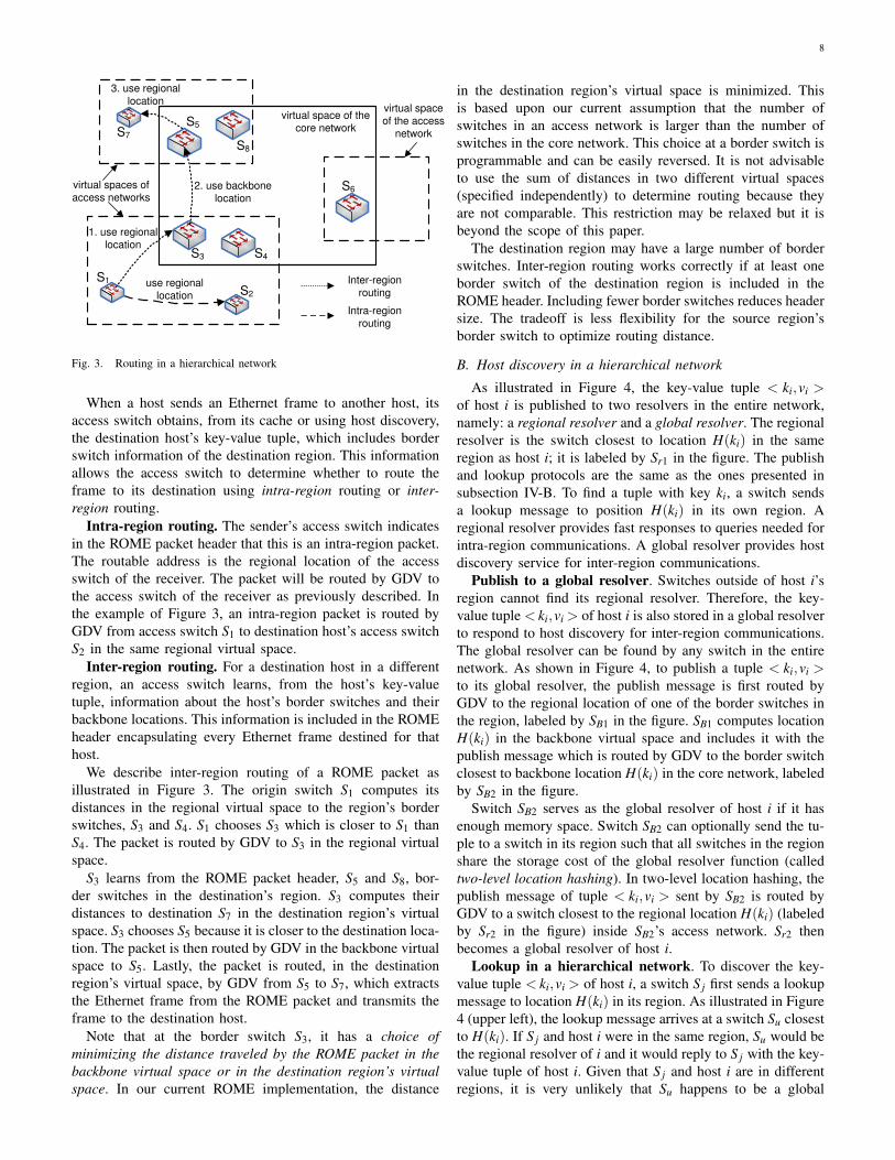
Fig. 3. Routing in a hierarchical network
When a host sends an Ethernet frame to another host, itsaccess switch obtains, from its cache or using host discovery,the destination host’s key-value tuple, which includes borderswitch information of the destination region. This informationallows the access switch to determine whether to route theframe to its destination using intra-region routing or inter-region routing.
Intra-region routing. The sender’s access switch indicatesin the ROME packet header that this is an intra-region packet.The routable address is the regional location of the accessswitch of the receiver. The packet will be routed by GDV tothe access switch of the receiver as previously described. Inthe example of Figure 3, an intra-region packet is routed byGDV from access switch S1 to destination host’s access switchS2 in the same regional virtual space.
Inter-region routing. For a destination host in a differentregion, an access switch learns, from the host’s key-valuetuple, information about the host’s border switches and theirbackbone locations. This information is included in the ROMEheader encapsulating every Ethernet frame destined for thathost.
We describe inter-region routing of a ROME packet asillustrated in Figure 3. The origin switch S1 computes itsdistances in the regional virtual space to the region’s borderswitches, S3 and S4. S1 chooses S3 which is closer to S1 thanS4. The packet is routed by GDV to S3 in the regional virtualspace.
S3 learns from the ROME packet header, S5 and S8, bor-der switches in the destination’s region. S3 computes theirdistances to destination S7 in the destination region’s virtualspace. S3 chooses S5 because it is closer to the destination loca-tion. The packet is then routed by GDV in the backbone virtualspace to S5. Lastly, the packet is routed, in the destinationregion’s virtual space, by GDV from S5 to S7, which extractsthe Ethernet frame from the ROME packet and transmits theframe to the destination host.
Note that at the border switch S3, it has a choice ofminimizing the distance traveled by the ROME packet in thebackbone virtual space or in the destination region’s virtualspace. In our current ROME implementation, the distance
in the destination region’s virtual space is minimized. Thisis based upon our current assumption that the number ofswitches in an access network is larger than the number ofswitches in the core network. This choice at a border switch isprogrammable and can be easily reversed. It is not advisableto use the sum of distances in two different virtual spaces(specified independently) to determine routing because theyare not comparable. This restriction may be relaxed but it isbeyond the scope of this paper.
The destination region may have a large number of borderswitches. Inter-region routing works correctly if at least oneborder switch of the destination region is included in theROME header. Including fewer border switches reduces headersize. The tradeoff is less flexibility for the source region’sborder switch to optimize routing distance.
B. Host discovery in a hierarchical network
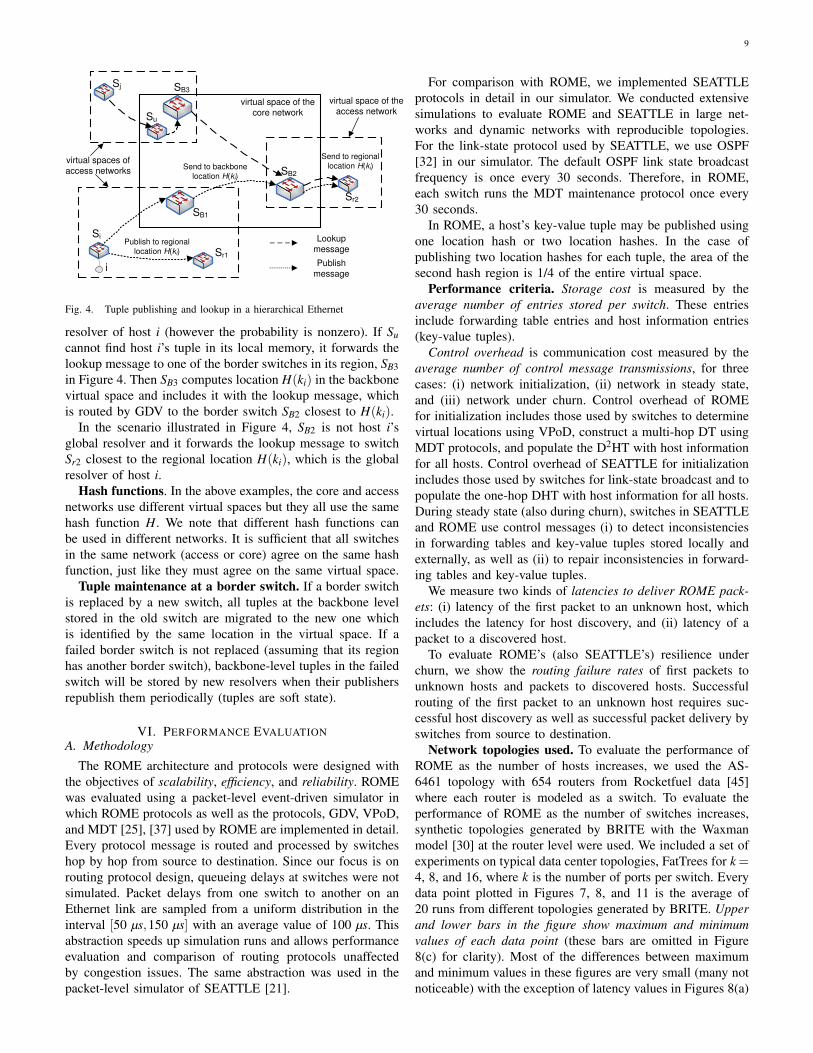
As illustrated in Figure 4, the key-value tuple < ki,vi >of host i is published to two resolvers in the entire network,namely: a regional resolver and a global resolver. The regionalresolver is the switch closest to location H(ki) in the sameregion as host i; it is labeled by Sr1 in the figure. The publishand lookup protocols are the same as the ones presented insubsection IV-B. To find a tuple with key ki, a switch sendsa lookup message to position H(ki) in its own region. Aregional resolver provides fast responses to queries needed forintra-region communications. A global resolver provides hostdiscovery service for inter-region communications.
Publish to a global resolver. Switches outside of host i’sregion cannot find its regional resolver. Therefore, the key-value tuple < ki,vi > of host i is also stored in a global resolverto respond to host discovery for inter-region communications.The global resolver can be found by any switch in the entirenetwork. As shown in Figure 4, to publish a tuple < ki,vi >to its global resolver, the publish message is first routed byGDV to the regional location of one of the border switches inthe region, labeled by SB1 in the figure. SB1 computes locationH(ki) in the backbone virtual space and includes it with thepublish message which is routed by GDV to the border switchclosest to backbone location H(ki) in the core network, labeledby SB2 in the figure.
Switch SB2 serves as the global resolver of host i if it hasenough memory space. Switch SB2 can optionally send the tu-ple to a switch in its region such that all switches in the regionshare the storage cost of the global resolver function (calledtwo-level location hashing). In two-level location hashing, thepublish message of tuple < ki,vi > sent by SB2 is routed byGDV to a switch closest to the regional location H(ki) (labeledby Sr2 in the figure) inside SB2’s access network. Sr2 thenbecomes a global resolver of host i.
Lookup in a hierarchical network. To discover the key-value tuple < ki,vi > of host i, a switch S j first sends a lookupmessage to location H(ki) in its region. As illustrated in Figure4 (upper left), the lookup message arrives at a switch Su closestto H(ki). If S j and host i were in the same region, Su would bethe regional resolver of i and it would reply to S j with the key-value tuple of host i. Given that S j and host i are in differentregions, it is very unlikely that Su happens to be a global
9
virtual spaces of access networks
virtual space of the core network
Publishmessage
Lookup message
Publish to regional
location H(ki)
Si
Sr1
SB1
SB3Sj
i
SB2
Sr2
Send to backbone
location H(ki)
Send to regional
location H(ki)
Su
virtual space of the access network
Fig. 4. Tuple publishing and lookup in a hierarchical Ethernet
resolver of host i (however the probability is nonzero). If Sucannot find host i’s tuple in its local memory, it forwards thelookup message to one of the border switches in its region, SB3in Figure 4. Then SB3 computes location H(ki) in the backbonevirtual space and includes it with the lookup message, whichis routed by GDV to the border switch SB2 closest to H(ki).
In the scenario illustrated in Figure 4, SB2 is not host i’sglobal resolver and it forwards the lookup message to switchSr2 closest to the regional location H(ki), which is the globalresolver of host i.
Hash functions. In the above examples, the core and accessnetworks use different virtual spaces but they all use the samehash function H. We note that different hash functions canbe used in different networks. It is sufficient that all switchesin the same network (access or core) agree on the same hashfunction, just like they must agree on the same virtual space.
Tuple maintenance at a border switch. If a border switchis replaced by a new switch, all tuples at the backbone levelstored in the old switch are migrated to the new one whichis identified by the same location in the virtual space. If afailed border switch is not replaced (assuming that its regionhas another border switch), backbone-level tuples in the failedswitch will be stored by new resolvers when their publishersrepublish them periodically (tuples are soft state).
VI. PERFORMANCE EVALUATIONA. Methodology
The ROME architecture and protocols were designed withthe objectives of scalability, efficiency, and reliability. ROMEwas evaluated using a packet-level event-driven simulator inwhich ROME protocols as well as the protocols, GDV, VPoD,and MDT [25], [37] used by ROME are implemented in detail.Every protocol message is routed and processed by switcheshop by hop from source to destination. Since our focus is onrouting protocol design, queueing delays at switches were notsimulated. Packet delays from one switch to another on anEthernet link are sampled from a uniform distribution in theinterval [50 µs,150 µs] with an average value of 100 µs. Thisabstraction speeds up simulation runs and allows performanceevaluation and comparison of routing protocols unaffectedby congestion issues. The same abstraction was used in thepacket-level simulator of SEATTLE [21].
For comparison with ROME, we implemented SEATTLEprotocols in detail in our simulator. We conducted extensivesimulations to evaluate ROME and SEATTLE in large net-works and dynamic networks with reproducible topologies.For the link-state protocol used by SEATTLE, we use OSPF[32] in our simulator. The default OSPF link state broadcastfrequency is once every 30 seconds. Therefore, in ROME,each switch runs the MDT maintenance protocol once every30 seconds.
In ROME, a host’s key-value tuple may be published usingone location hash or two location hashes. In the case ofpublishing two location hashes for each tuple, the area of thesecond hash region is 1/4 of the entire virtual space.
Performance criteria. Storage cost is measured by theaverage number of entries stored per switch. These entriesinclude forwarding table entries and host information entries(key-value tuples).
Control overhead is communication cost measured by theaverage number of control message transmissions, for threecases: (i) network initialization, (ii) network in steady state,and (iii) network under churn. Control overhead of ROMEfor initialization includes those used by switches to determinevirtual locations using VPoD, construct a multi-hop DT usingMDT protocols, and populate the D2HT with host informationfor all hosts. Control overhead of SEATTLE for initializationincludes those used by switches for link-state broadcast and topopulate the one-hop DHT with host information for all hosts.During steady state (also during churn), switches in SEATTLEand ROME use control messages (i) to detect inconsistenciesin forwarding tables and key-value tuples stored locally andexternally, as well as (ii) to repair inconsistencies in forward-ing tables and key-value tuples.
We measure two kinds of latencies to deliver ROME pack-ets: (i) latency of the first packet to an unknown host, whichincludes the latency for host discovery, and (ii) latency of apacket to a discovered host.
To evaluate ROME’s (also SEATTLE’s) resilience underchurn, we show the routing failure rates of first packets tounknown hosts and packets to discovered hosts. Successfulrouting of the first packet to an unknown host requires suc-cessful host discovery as well as successful packet delivery byswitches from source to destination.
Network topologies used. To evaluate the performance ofROME as the number of hosts increases, we used the AS-6461 topology with 654 routers from Rocketfuel data [45]where each router is modeled as a switch. To evaluate theperformance of ROME as the number of switches increases,synthetic topologies generated by BRITE with the Waxmanmodel [30] at the router level were used. We included a set ofexperiments on typical data center topologies, FatTrees for k =4, 8, and 16, where k is the number of ports per switch. Everydata point plotted in Figures 7, 8, and 11 is the average of20 runs from different topologies generated by BRITE. Upperand lower bars in the figure show maximum and minimumvalues of each data point (these bars are omitted in Figure8(c) for clarity). Most of the differences between maximumand minimum values in these figures are very small (many notnoticeable) with the exception of latency values in Figures 8(a)

10
0 0.4 0.8 1.2 1.6 2 2.41
2
4
8
Time (s)
GD
V R
outin
g st
retc
h
VPoD (2D)VPoD (3D)
(a) Routing stretch convergence
100 400 700 10000
20
40
60
80
100
No. of nodes
Sto
rage
cos
t
VPoD(3D)VPoD(2D)Num of neighbors
(b) Storage cost
Fig. 5. Performance comparison for 2D and 3D virtual spaces
and (b).
B. Choice of dimensionality
We evaluated GDV routing performance in 2D and 3Dspaces for Brite networks. The VPoD adjustment period wasset at 100 ms. Figure 5(a) shows the GDV routing stretch(equal to routing latency divided by shortest path latency)versus time for simulation runs in 2D and 3D. At the startof each simulation run, the routing stretch was relatively highfor both 2D and 3D because node locations were randomlyselected. After a number of VPoD adjustments, the routingstretch converged in 2.5 seconds of simulated time to 1.25 and1.15 seconds for 2D and 3D, respectively. Our experimentsfor Rocketfuel networks show similar results. Figure 5(b)shows the per node storage cost (average number of entriesin a forwarding table) of ROME in 2D and 3D for BRITEnetworks. The average number of directly-connected neighborsis shown as the baseline for comparison. Clearly, runningVPoD in 3D requires a higher storage cost than in 2D.From experimental results (presented below), we found thatthe routing latency provided by 2D is already very good.Therefore, we choose to use 2D rather than 3D (or 4D) tominimize the storage of ROME switches and control messageoverhead.
C. Varying the number of hosts
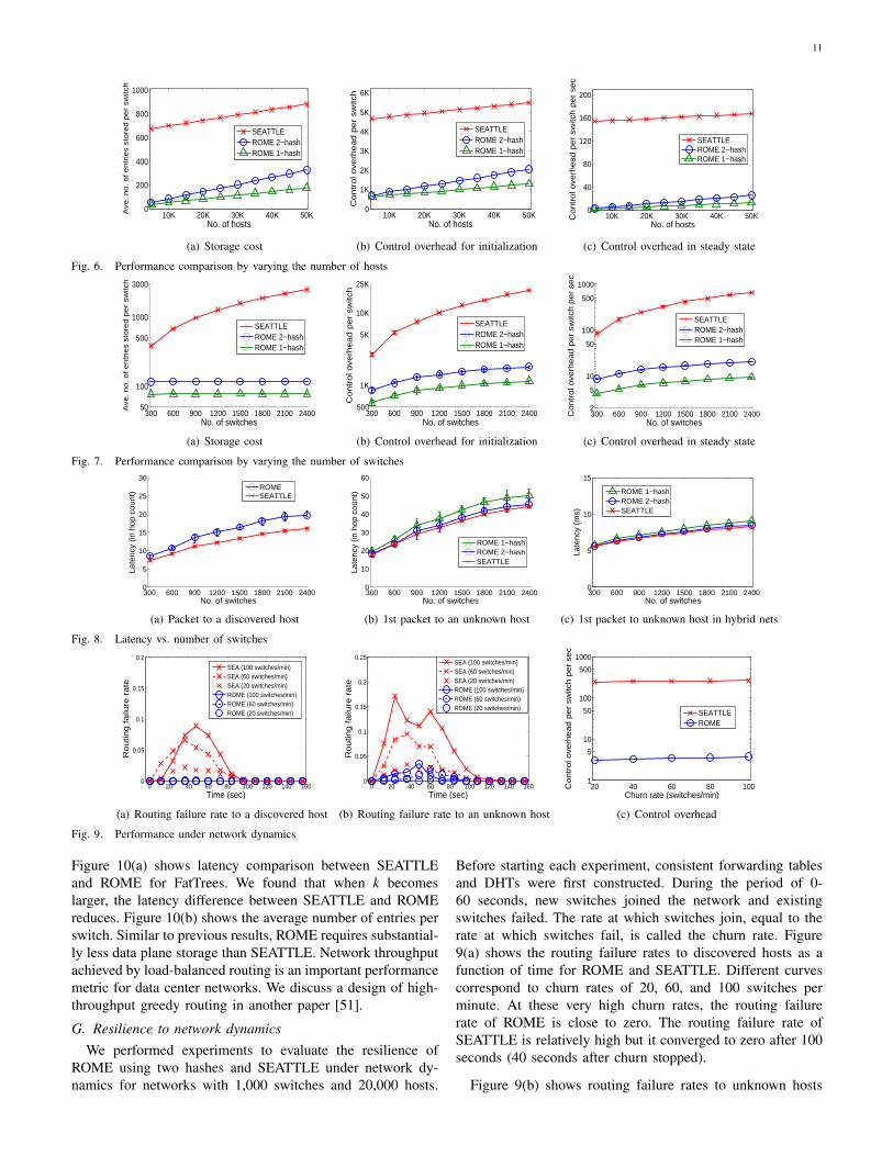
For a network with n switches and m hosts, a conventionalEthernet requires O(nm) storage per switch while SEATTLErequires O(m) storage per switch. We found that ROME alsorequires O(m) storage per switch with a much smaller abso-lute value than that of SEATTLE. We performed simulationexperiments for a fixed topology (Rocketfuel AS-6461) with654 switches. The number of hosts at each switch varies. Thetotal number of hosts of the entire network varies from 5,000to 50,000. We found that the storage costs of ROME andSEATTLE for forwarding tables are constant, while their stor-age costs for host information increase linearly as the numberof hosts increases. In Figure 6(a), the difference between thestorage costs of ROME and SEATTLE is the difference in theirforwarding table storage costs per switch. The host informationstorage cost of ROME using two (location) hashes is close to,but not larger than, twice the storage cost of ROME using onehash.
Figures 6(b) and 6(c) show the control overheads of ROMEand SEATTLE, for initialization and in steady state. Wefound that the control overheads for constructing and updatingSEATTLE’s one-hop DHT and ROME’s D2HT both increase
k = 4 k = 8 k = 160
2
4
6
8
10
Late
ncy
(in h
op c
ount
)
SEATTLEROME
(a) Routing latency
k = 4 k = 8 k = 160
100
200
300
400
Ave
. no.
of e
ntrie
s st
ored
per
sw
itch
SEATTLEROME
(b) Storage cost
Fig. 10. Performance comparison for FatTrees
linearly with m and they are about the same. However, thefigures show that ROME’s overall control overhead is muchsmaller than that of SEATTLE. This is because ROME’sforwarding table construction and maintenance are flooding-free and thus much more efficient.
D. Varying the number of switches
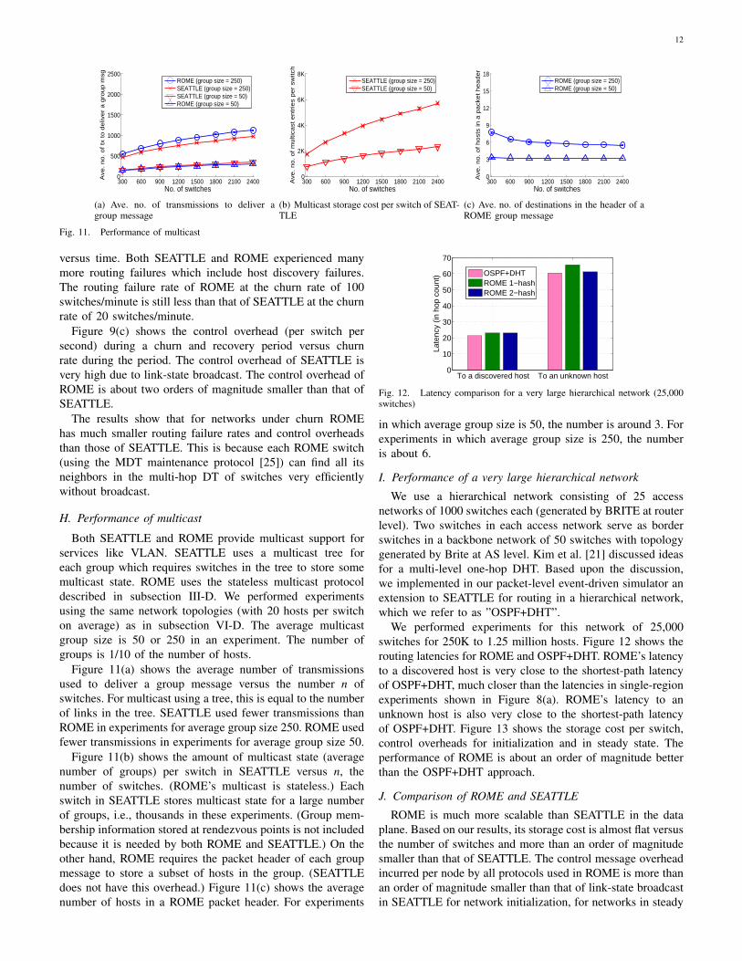
In this set of experiments the number n of switches increasesfrom 300 to 2,400 while the average number of hosts perswitch is fixed at 20. Thus the total number of hosts of thenetwork also increases linearly from 6,000 to 48,000. Theresults are shown in Figure 7. Note that each y-axis is inlogarithmic scale.
Figure 7(a) shows storage cost versus n. Note that while thestorage cost of SEATTLE increases with n, ROME’s storagecost is almost flat versus n. At n = 2400, ROME’s storage costis less than 1/20 of the storage of SEATTLE.
Figures 7(b) and (c) show that the control overheads ofROME for initialization and in steady state are both substan-tially lower than those of SEATTLE. These control overheadsof ROME increase slightly with n. This is because the pathsfrom publishers to resolvers in a larger network are longer.
E. Routing latencies
These experiments were performed using the same networktopologies (with 20 hosts per switch on average) as in subsec-tion VI-D. Figure 8(a) shows the latency (in average numberof hops) of packets to discovered hosts. Note that ROME’slatency is not much higher than the shortest-path latency ofSEATTLE.
Figure 8(b) shows the latency of first packets to unknownhosts for SEATTLE and for ROME using one and two hashes.This latency includes the round-trip delay between senderand resolver, and the subsequent latency from sender todestination. By using two hashes instead of one, the latencyof ROME improves and becomes very close to the latencyof SEATTLE. At n = 300, the latency of ROME (2-hash) isactually smaller than the latency of SEATTLE.
We also performed experiments to evaluate ROME andSEATTLE latencies in hybrid networks, where 20% of theswitches are replaced by wireless switches. The packet delayof a wireless hop is sampled uniformly from [5 ms,15 ms]with an average value of 10 ms, much higher than 100 µs fora wired connection. Figure 8(c) shows that SEATTLE still hasthe lowest latency, but the difference between SEATTLE andROME is negligible.
F. Data center topologies
We evaluated the performance of ROME running on typicaldata center topologies, i.e., FatTrees for k = 4, 8, and 16.
11
10K 20K 30K 40K 50K0
200
400
600
800
1000
No. of hosts
Ave
. n
o.
of e
ntr
ies
sto
red
pe
r sw
itch
SEATTLEROME 2−hashROME 1−hash
(a) Storage cost
10K 20K 30K 40K 50K0
1K
2K
3K
4K
5K
6K
No. of hosts
Co
ntr
ol o
verh
ea
d p
er
switc
h
SEATTLEROME 2−hashROME 1−hash
(b) Control overhead for initialization
10K 20K 30K 40K 50K0
40
80
120
160
200
No. of hosts
Co
ntr
ol o
verh
ea
d p
er
switc
h p
er
sec
SEATTLEROME 2−hashROME 1−hash
(c) Control overhead in steady state
Fig. 6. Performance comparison by varying the number of hosts
300 600 900 1200 1500 1800 2100 240050
100
500
1000
3000
No. of switches
Ave
. n
o. o
f e
ntr
ies
sto
red
pe
r sw
itch
SEATTLEROME 2−hashROME 1−hash
(a) Storage cost
300 600 900 1200 1500 1800 2100 2400500
1K
5K
10K
25K
No. of switches
Co
ntr
ol o
verh
ea
d p
er
switc
h
SEATTLEROME 2−hashROME 1−hash
(b) Control overhead for initialization
300 600 900 1200 1500 1800 2100 24002
5
10
50
100
500
1000
No. of switches
Co
ntr
ol o
verh
ea
d p
er
switc
h p
er
sec
SEATTLEROME 2−hashROME 1−hash
(c) Control overhead in steady state
Fig. 7. Performance comparison by varying the number of switches
300 600 900 1200 1500 1800 2100 24000
5
10
15
20
25
30
No. of switches
Late
ncy
(in h
op c
ount
) ROMESEATTLE
(a) Packet to a discovered host
300 600 900 1200 1500 1800 2100 24000
10
20
30
40
50
60
No. of switches
Late
ncy
(in h
op c
ount
)
ROME 1−hashROME 2−hashSEATTLE
(b) 1st packet to an unknown host
300 600 900 1200 1500 1800 2100 24000
5
10
15
No. of switches
Late
ncy
(ms)
ROME 1−hashROME 2−hashSEATTLE
(c) 1st packet to unknown host in hybrid nets
Fig. 8. Latency vs. number of switches
0 20 40 60 80 100 120 140 1600
0.05
0.1
0.15
0.2
Time (sec)
Routin
g failu
re r
ate
SEA (100 switches/min)SEA (60 switches/min)SEA (20 switches/min)ROME (100 switches/min)ROME (60 switches/min)ROME (20 switches/min)
(a) Routing failure rate to a discovered host
0 20 40 60 80 100 120 140 1600
0.05
0.1
0.15
0.2
0.25
Time (sec)
Routin
g failu
re r
ate
SEA (100 switches/min)SEA (60 switches/min)SEA (20 switches/min)ROME (100 switches/min)ROME (60 switches/min)ROME (20 switches/min)
(b) Routing failure rate to an unknown host
20 40 60 80 1001
5
10
50
100
500
1000
Churn rate (switches/min)
Contr
ol o
verh
ead p
er
switc
h p
er
sec
SEATTLEROME
(c) Control overhead
Fig. 9. Performance under network dynamics
Figure 10(a) shows latency comparison between SEATTLEand ROME for FatTrees. We found that when k becomeslarger, the latency difference between SEATTLE and ROMEreduces. Figure 10(b) shows the average number of entries perswitch. Similar to previous results, ROME requires substantial-ly less data plane storage than SEATTLE. Network throughputachieved by load-balanced routing is an important performancemetric for data center networks. We discuss a design of high-throughput greedy routing in another paper [51].
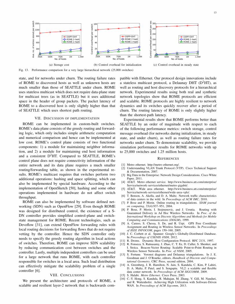
G. Resilience to network dynamicsWe performed experiments to evaluate the resilience of
ROME using two hashes and SEATTLE under network dy-namics for networks with 1,000 switches and 20,000 hosts.
Before starting each experiment, consistent forwarding tablesand DHTs were first constructed. During the period of 0-60 seconds, new switches joined the network and existingswitches failed. The rate at which switches join, equal to therate at which switches fail, is called the churn rate. Figure9(a) shows the routing failure rates to discovered hosts as afunction of time for ROME and SEATTLE. Different curvescorrespond to churn rates of 20, 60, and 100 switches perminute. At these very high churn rates, the routing failurerate of ROME is close to zero. The routing failure rate ofSEATTLE is relatively high but it converged to zero after 100seconds (40 seconds after churn stopped).
Figure 9(b) shows routing failure rates to unknown hosts
12
300 600 900 1200 1500 1800 2100 24000
500
1000
1500
2000
2500
No. of switches
Ave
. no. of tx
to d
eliv
er
a g
roup m
sg
ROME (group size = 250)SEATTLE (group size = 250)SEATTLE (group size = 50)ROME (group size = 50)
(a) Ave. no. of transmissions to deliver agroup message
300 600 900 1200 1500 1800 2100 24000
2K
4K
6K
8K
No. of switches
Ave
. no. of m
ulti
cast
entr
ies
per
switc
h
SEATTLE (group size = 250)SEATTLE (group size = 50)
(b) Multicast storage cost per switch of SEAT-TLE
300 600 900 1200 1500 1800 2100 24000
3
6
9
12
15
18
No. of switches
Ave
. no. of host
s in
a p
ack
et header
ROME (group size = 250)ROME (group size = 50)
(c) Ave. no. of destinations in the header of aROME group message
Fig. 11. Performance of multicast
versus time. Both SEATTLE and ROME experienced manymore routing failures which include host discovery failures.The routing failure rate of ROME at the churn rate of 100switches/minute is still less than that of SEATTLE at the churnrate of 20 switches/minute.
Figure 9(c) shows the control overhead (per switch persecond) during a churn and recovery period versus churnrate during the period. The control overhead of SEATTLE isvery high due to link-state broadcast. The control overhead ofROME is about two orders of magnitude smaller than that ofSEATTLE.
The results show that for networks under churn ROMEhas much smaller routing failure rates and control overheadsthan those of SEATTLE. This is because each ROME switch(using the MDT maintenance protocol [25]) can find all itsneighbors in the multi-hop DT of switches very efficientlywithout broadcast.
H. Performance of multicast
Both SEATTLE and ROME provide multicast support forservices like VLAN. SEATTLE uses a multicast tree foreach group which requires switches in the tree to store somemulticast state. ROME uses the stateless multicast protocoldescribed in subsection III-D. We performed experimentsusing the same network topologies (with 20 hosts per switchon average) as in subsection VI-D. The average multicastgroup size is 50 or 250 in an experiment. The number ofgroups is 1/10 of the number of hosts.
Figure 11(a) shows the average number of transmissionsused to deliver a group message versus the number n ofswitches. For multicast using a tree, this is equal to the numberof links in the tree. SEATTLE used fewer transmissions thanROME in experiments for average group size 250. ROME usedfewer transmissions in experiments for average group size 50.
Figure 11(b) shows the amount of multicast state (averagenumber of groups) per switch in SEATTLE versus n, thenumber of switches. (ROME’s multicast is stateless.) Eachswitch in SEATTLE stores multicast state for a large numberof groups, i.e., thousands in these experiments. (Group mem-bership information stored at rendezvous points is not includedbecause it is needed by both ROME and SEATTLE.) On theother hand, ROME requires the packet header of each groupmessage to store a subset of hosts in the group. (SEATTLEdoes not have this overhead.) Figure 11(c) shows the averagenumber of hosts in a ROME packet header. For experiments
To a discovered host To an unknown host0
10
20
30
40
50
60
70
Late
ncy
(in h
op c
ount
) OSPF+DHTROME 1−hashROME 2−hash
Fig. 12. Latency comparison for a very large hierarchical network (25,000switches)
in which average group size is 50, the number is around 3. Forexperiments in which average group size is 250, the numberis about 6.
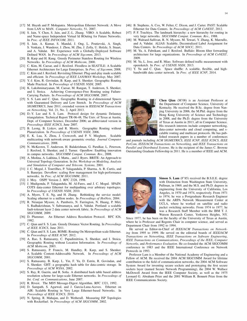
I. Performance of a very large hierarchical network
We use a hierarchical network consisting of 25 accessnetworks of 1000 switches each (generated by BRITE at routerlevel). Two switches in each access network serve as borderswitches in a backbone network of 50 switches with topologygenerated by Brite at AS level. Kim et al. [21] discussed ideasfor a multi-level one-hop DHT. Based upon the discussion,we implemented in our packet-level event-driven simulator anextension to SEATTLE for routing in a hierarchical network,which we refer to as ”OSPF+DHT”.
We performed experiments for this network of 25,000switches for 250K to 1.25 million hosts. Figure 12 shows therouting latencies for ROME and OSPF+DHT. ROME’s latencyto a discovered host is very close to the shortest-path latencyof OSPF+DHT, much closer than the latencies in single-regionexperiments shown in Figure 8(a). ROME’s latency to anunknown host is also very close to the shortest-path latencyof OSPF+DHT. Figure 13 shows the storage cost per switch,control overheads for initialization and in steady state. Theperformance of ROME is about an order of magnitude betterthan the OSPF+DHT approach.
J. Comparison of ROME and SEATTLE
ROME is much more scalable than SEATTLE in the dataplane. Based on our results, its storage cost is almost flat versusthe number of switches and more than an order of magnitudesmaller than that of SEATTLE. The control message overheadincurred per node by all protocols used in ROME is more thanan order of magnitude smaller than that of link-state broadcastin SEATTLE for network initialization, for networks in steady
13
250K 500K 750K 1M 1.25M0
300
600
900
1200
1500
No. of hosts
Ave
. n
o. o
f e
ntr
ies
sto
red
pe
r sw
itch
OSPF+DHTROME 2−hashROME 1−hash
(a) Storage cost
250K 500K 750K 1M 1.25M0
2K
4K
6K
8K
10K
No. of hosts
Co
ntr
ol o
verh
ea
d p
er
switc
h
OSPF+DHTROME 2−hashROME 1−hash
(b) Control overhead for initialization
250K 500K 750K 1M 1.25M0
50
100
150
200
250
300
No. of hosts
Co
ntr
ol o
verh
ea
d p
er
switc
h p
er
sec
OSPF+DHTROME 2−hashROME 1−hash
(c) Control overhead in steady state
Fig. 13. Performance comparison for a very large hierarchical network (25,000 switches)
state, and for networks under churn. The routing failure ratesof ROME to discovered hosts as well as unknown hosts aremuch smaller than those of SEATTLE under churn. ROMEuses stateless multicast which does not require data-plane statefor multicast trees (as in SEATTLE) but it uses additionalspace in the header of group packets. The packet latency ofROME to a discovered host is only slightly higher than thatof SEATTLE which uses shortest path routing.
VII. DISCUSSION OF IMPLEMENTATION
ROME can be implemented in custom-built switches.ROME’s data plane consists of the greedy routing and forward-ing logic, which only includes simple arithmetic computationand numerical comparison and hence can be implemented atlow cost. ROME’s control plane consists of two functionalcomponents: 1) a module for maintaining neighbor informa-tion, and 2) a module for maintaining end host informationand a consistent D2HT. Compared to SEATTLE, ROME’scontrol plane does not require connectivity information of theentire network and its data plane requires a much smallerrouting/forwarding table, as shown in the experimental re-sults. ROME’s multicast requires that switches perform twoadditional operations: hashing and space splitting, which canalso be implemented by special hardware. According to theimplementation of OpenSketch [50], hashing and some otheroperations implemented in hardware do not affect switchthroughput.
ROME can also be implemented by software defined net-working (SDN) such as OpenFlow [29]. Even though ROMEwas designed for distributed control, the existence of a S-DN controller provides simplified control-plane and switch-state management for ROME. Recent technologies, such asDevoflow [31], can extend OpenFlow forwarding rules withlocal routing decisions for forwarding flows that do not requirevetting by the controller. Hence the SDN controller onlyneeds to specify the greedy routing algorithm in local actionsof switches. Therefore, ROME can improve SDN scalabilityby reducing communication cost between switches and thecontroller. Lastly, multiple independent controllers can be usedfor a large network that runs ROME, with each controllerresponsible for switches in a local area. Such load distributioncan effectively mitigate the scalability problem of a singlecontroller [6].
VIII. CONCLUSIONS
We present the architecture and protocols of ROME, ascalable and resilient layer-2 network that is backwards com-
patible with Ethernet. Our protocol design innovations includea stateless multicast protocol, a Delaunay DHT (D2HT), aswell as routing and host discovery protocols for a hierarchicalnetwork. Experimental results using both real and syntheticnetwork topologies show that ROME protocols are efficientand scalable. ROME protocols are highly resilient to networkdynamics and its switches quickly recover after a period ofchurn. The routing latency of ROME is only slightly higherthan the shortest-path latency.
Experimental results show that ROME performs better thanSEATTLE by an order of magnitude with respect to eachof the following performance metrics: switch storage, controlmessage overhead (for networks during initialization, in steadystate, and under churn), as well as routing failure rates fornetworks under churn. To demonstrate scalability, we providesimulation performance results for ROME networks with upto 25,000 switches and 1.25 million hosts.
REFERENCES
[1] Metro ethernet. http://metro-ethernet.org/.[2] Understanding VLAN Trunk Protocol (VTP). Cisco Technical Support
& Documentation, 2007.[3] Big Data in the Enterprise: Network Design Considerations. Cisco White
Paper, 2011.[4] AT&T. Metro ethernet service. http://www.business.att.com/enterprise/
Service/network-services/ethernet/metro-gigabit/.[5] AT&T. Wide area ethernet. http://www.business.att.com/enterprise/
Service/network-services/ethernet/wide-area-vpls/.[6] T. Benson, A. Akella, and D. A. Maltz. Network traffic characteristics
of data centers in the wild. In Proceedings of ACM IMC, 2010.[7] P. Bose and P. Morin. Online routing in triangulations. SIAM journal
on computing, 33(4):937–951, 2004.[8] P. Bose, P. Morin, I. Stojmenovic, and J. Urrutia. Routing with
Guaranteed Delivery in Ad Hoc Wireless Networks. In Proc. of theInternational Workshop on Discrete Algorithms and Methods for MobileComputing and Communications (DIALM), 1999.
[9] A. Caruso, S. Chessa, S. De, and R. Urpi. GPS Free CoordinateAssignment and Routing in Wireless Sensor Networks. In Proceedingsof IEEE INFOCOM, pages 150–160, 2005.
[10] J. C. Corbett et al. Spanner: Google’s Globally-Distributed Database.In Proceedings of USENIX OSDI, 2012.
[11] R. Droms. Dynamic Host Configuration Protocol. RFC 2131, 1997.[12] R. Fonseca, S. Ratnasamy, J. Zhao, C. T. Ee, D. Culler, S. Shenker, and
I. Stoica. Beacon-Vector Routing: Scalable Point-to-Point Routing inWireless Sensor Networks. In Proc. of NSDI, 2005.
[13] S. Fortune. Voronoi diagrams and Delaunay triangulations. In J. E.Goodman and J. O’Rourke, editors, Handbook of Discrete and Compu-tational Geometry. CRC Press, second edition, 2004.
[14] A. Greenberg, J. R. Hamilton, N. Jain, S. Kandula, C. Kim, P. Lahiri,D. A. Maltz, P. Patel, and S. Sengupta. VL2: a scalable and flexibledata center network. In Proceedings of ACM SIGCOMM, 2009.
[15] S. Halabi. Metro Ethernet. Cisco Press, 2003.[16] C.-Y. Hong, S. Kandula, R. Mahajan, M. Zhang, V. Gill, M. Nanduri,
and R. Wattenhofer. Achieving High Utilization with Software-DrivenWAN. In Proceedings of ACM Sigcomm, 2013.
14
[17] M. Huynh and P. Mohapatra. Metropolitan Ethernet Network: A Movefrom LAN to MAN. Computer Networks, 51, 2007.
[18] S. Jain, Y. Chen, S. Jain, and Z.-L. Zhang. VIRO: A Scalable, Robustand Name-space Independent Virtual Id ROuting for Future Networks.In Proc. of IEEE INFOCOM, 2011.
[19] S. Jain, A. Kumar, S. Mandal, J. Ong, L. Poutievski, A. Singh,S. Venkata, J. Wanderer, J. Zhou, M. Zhu, J. Zolla, U. Holzle, S. Stuart,and A. Vahdat. B4: Experience with a Globally-Deployed SoftwareDefined WAN. In Proceedings of ACM Sigcomm, 2013.
[20] B. Karp and H. Kung. Greedy Perimeter Stateless Routing for WirelessNetworks. In Proceedings of ACM Mobicom, 2000.
[21] C. Kim, M. Caesar, and J. Rexford. Floodless in SEATTLE: A ScalableEthernet Architecture for Large Enterprises. In Proc. of Sigcomm, 2008.
[22] C. Kim and J. Rexford. Revisiting Ethernet: Plug-and-play made scalableand efficient. In Proceedings of IEEE LAN/MAN Workshop, May 2007.
[23] Y.-J. Kim, R. Govindan, B. Karp, and S. Shenker. Geographic RoutingMade Practical. In Proceedings of USENIX NSDI, 2005.
[24] K. Lakshminaryanan, M. Caesar, M. Rangan, T. Anderson, S. Shenker,and I. Stoica. Achieving Convergence-Free Routing using Failure-Carrying Packets. In Proceedings of ACM SIGCOMM, 2007.
[25] S. S. Lam and C. Qian. Geographic Routing in d-dimensional Spaceswith Guaranteed Delivery and Low Stretch. In Proceedings of ACMSIGMETRICS, June 2011; extended version in IEEE/ACM Transactionson Networking, Vol. 21, No. 2, April 2013.
[26] D.-Y. Lee and S. S. Lam. Protocol design for dynamic Delaunaytriangulation. Technical Report TR-06-48, The Univ. of Texas at Austin,Dept. of Computer Science, December 2006; an abbreviated version inProceedings IEEE ICDCS, June 2007.
[27] B. Leong, B. Liskov, and R. Morris. Geographic Routing withoutPlanarization. In Proceedings of USENIX NSDI, 2006.
[28] E. K. Lua, X. Zhou, J. Crowcroft, and P. V. Mieghem. Scalablemulticasting with network-aware geometric overlay. Journal ComputerCommunications, 2008.
[29] N. McKeown, T. Anderson, H. Balakrishnan, G. Parulkar, L. Peterson,J. Rexford, S. Shenker, and J. Turner. Openflow: Enabling innovationin campus networks. SIGCOMM Comput. Commun. Rev., 2008.
[30] A. Medina, A. Lakhina, I. Matta, , and J. Byers. BRITE: An Approach toUniversal Topology Generation. In Int. Workshop on Modeling, Analysisand Simulation of Computer and Telecom. Systems, 2001.
[31] J. C. Mogul, J. Tourrilhes, P. Yalagandula, P. Sharma, A. R. Curtis, andS. Banerjee. Devoflow: scaling flow management for high-performancenetworks. In Proc. of ACM SIGCOMM, 2011.
[32] J. Moy. OSPF Version 2. RFC 2328, 1998.[33] J. Mudigonda, P. Yalagandula, M. Al-Fares, and J. C. Mogul. SPAIN:
COTS data-center Ethernet for multipathing over arbitrary topologies.In Proceedings of USENIX NSDI, 2010.
[34] A. Myers, T. E. Ng, and H. Zhang. Rethinking the service model:Scaling ethernet to a million nodes. In Proceedings of HotNets, 2004.
[35] R. Niranjan Mysore, A. Pamboris, N. Farrington, N. Huang, P. Miri,S. Radhakrishnan, V. Subramanya, and A. Vahdat. Portland: a scalablefault-tolerant layer 2 data center network fabric. In Proceedings of ACMSIGCOMM, 2009.
[36] D. Plummer. An Ethernet Address Resolution Protocol. RFC 826,1982.
[37] C. Qian and S. S. Lam. Greedy Distance Vector Routing. In Proceedingsof IEEE ICDCS, June 2011.
[38] C. Qian and S. S. Lam. ROME: Routing On Metropolitan-scale Ethernet.In Proceedings of IEEE ICNP, 2012.
[39] A. Rao, S. Ratnasamy, C. Papadimitriou, S. Shenker, and I. Stoica.Geographic Routing without Location Information. In Proceedings ofACM Mobicom, 2003.
[40] S. Ratnasamy, P. Francis, M. Handley, R. Karp, and S. Shenker.A Scalable Content-Addressable Network. In Proceedings of ACMSIGCOMM, 2001.
[41] S. Ratnasamy, B. Karp, L. Yin, F. Yu, D. Estrin, R. Govindan, andS. Shenker. GHT: a geographic hash table for data-centric storage. InProceedings of ACM WSNA, 2002.
[42] S. Ray, R. Guerin, and R. Sofia. A distributed hash table based addressresolution scheme for large-scale Ethernet networks. In Proceedings ofInt. Conf. on Communications, June 2007.
[43] R. Rivest. The MD5 Message-Digest Algorithm. RFC 1321, 1992.[44] D. Sampath, S. Agarwal, and J. Garcia-Luna-Aceves. Ethernet on
AIR: Scalable Routing in Very Large Ethernet-based Networks. InProceedings of IEEE ICDCS, 2010.
[45] N. Spring, R. Mahajan, and D. Wetherall. Measuring ISP Topologieswith Rocketfuel. In Proceedings of ACM SIGCOMM, 2002.
[46] B. Stephens, A. Cox, W. Felter, C. Dixon, and J. Carter. PAST: ScalableEthernet for Data Centers. In Proceedings of ACM CoNEXT, 2012.
[47] P. F. Tsuchiya. The landmark hierarchy: a new hierarchy for routing invery large networks. SIGCOMM Comput. Commun. Rev., 1988.
[48] M. Walraed-Sullivan, R. N. Mysore, M. Tewari, Y. Zhang, K. Marzullo,and A. Vahdat. ALIAS: Scalable, Decentralized Label Assignment forData Centers. In Proceedings of ACM SOCC, 2011.
[49] M. Yu, A. Fabrikant, and J. Rexford. Buffalo: Bloom filter forwardingarchitecture for large organizations. In Proceedings of ACM CoNEXT,2009.
[50] M. Yu, L. Jose, and R. Miao. Software defined traffic measurement withopensketch. In Proc. of USENIX NSDI, 2013.
[51] Y. Yu and C. Qian. Space shuffle: A scalable, flexible, and high-bandwidth data center network. In Proc. of IEEE ICNP, 2014.
Chen Qian (M’08) is an Assistant Professor atthe Department of Computer Science, University ofKentucky. He received the B.Sc. degree from Nan-jing University in 2006, the M.Phil. degree from theHong Kong University of Science and Technologyin 2008, and the Ph.D. degree from the Universityof Texas at Austin in 2013, all in Computer Science.His research interests include computer networking,data-center networks and cloud computing, and s-calable routing and multicast protocols. He has pub-lished research papers in a number of conferences
and journals including ACM SIGMETRICS, IEEE ICNP, IEEE ICDCS, IEEEPerCom, IEEE/ACM Transactions on Networking, and IEEE Transactions onParallel and Distributed Systems. He is the recipient of the James C. BrowneOutstanding Graduate Fellowship in 2011. He is a member of IEEE and ACM.
Simon S. Lam (F’85) received the B.S.E.E. degreewith Distinction from Washington State University,Pullman, in 1969, and the M.S. and Ph.D. degrees inengineering from the University of California, LosAngeles, in 1970 and 1974, respectively. From 1971to 1974, he was a Postgraduate Research Engineerwith the ARPA Network Measurement Center atUCLA, where he worked on satellite and radiopacket switching networks. From 1974 to 1977, hewas a Research Staff Member with the IBM T. J.Watson Research Center, Yorktown Heights, NY.
Since 1977, he has been on the faculty of the University of Texas at Austin,where he is Professor and Regents Chair in computer science, and served asDepartment Chair from 1992 to 1994.
He served as Editor-in-Chief of IEEE/ACM Transactions on Network-ing from 1995 to 1999. He served on the editorial boards of IEEE/ACMTransactions on Networking, IEEE Transactions on Software Engineering,IEEE Transactions on Communications, Proceedings of the IEEE, ComputerNetworks, and Performance Evaluation. He co-founded the ACM SIGCOMMconference in 1983 and the IEEE International Conference on NetworkProtocols in 1993.
Professor Lam is a Member of the National Academy of Engineering and aFellow of ACM. He received the 2004 ACM SIGCOMM Award for lifetimecontribution to the field of communication networks, the 2004 ACM SoftwareSystem Award for inventing secure sockets and prototyping the first securesockets layer (named Secure Network Programming), the 2004 W. WallaceMcDowell Award from the IEEE Computer Society, as well as the 1975Leonard G. Abraham Prize and the 2001 William R. Bennett Prize from theIEEE Communications Society.