Embed Size (px)
Citation preview

A. Ruiz-Jimeno,ILD-Krakow-Sept2013
TRACKING IN ILD: A REVIEW

Outline— REQUIREMENTS— CURRENT SITUATION— HOW TO PROCEED(mainly silicon tracking)
A. Ruiz-Jimeno,ILD-Krakow-Sept2013
Thanks for their inputs to D.Moya, R. D. Settles, Y. Sugimoto, I. Vila and M. Vos

Requirements
A. Ruiz-Jimeno,ILD-Krakow-Sept2013
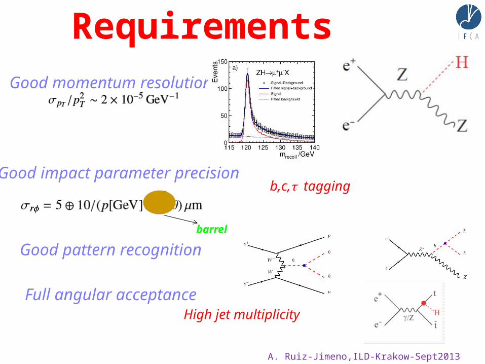
Good momentum resolution

Requirements
A. Ruiz-Jimeno,ILD-Krakow-Sept2013
Good momentum resolution
Good impact parameter precisionb,c, t tagging
barrel
Requirements
A. Ruiz-Jimeno,ILD-Krakow-Sept2013
Good momentum resolution
Good impact parameter precision
Good pattern recognition
Full angular acceptance
b,c, t tagging
barrel
High jet multiplicity

A. Ruiz-Jimeno,ILD-Krakow-Sept2013
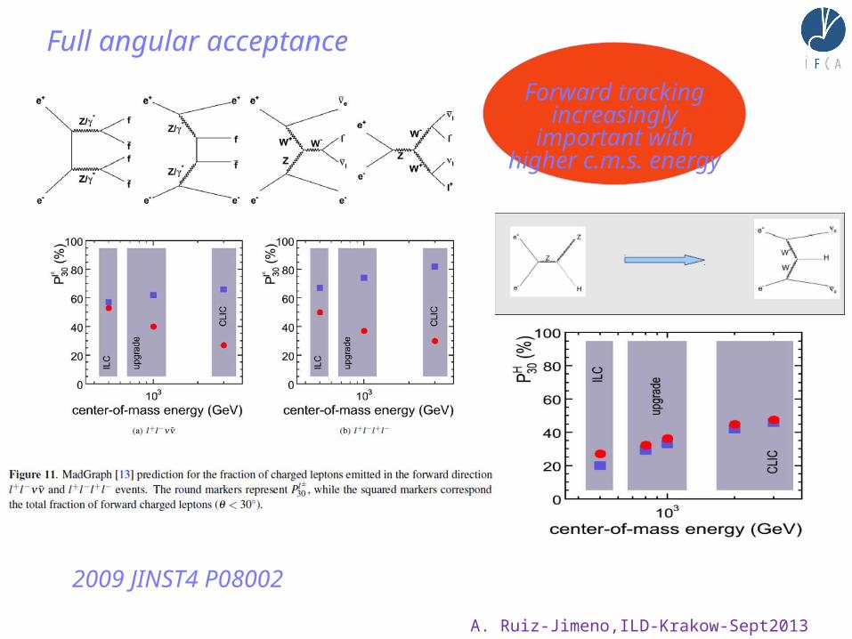
Full angular acceptance
Forward tracking increasingly important
with higher c.m.s. energy
2009 JINST4 P08002
A. Ruiz-Jimeno,ILD-Krakow-Sept2013
Full angular acceptance
Forward tracking increasingly important
with higher c.m.s. energy
2009 JINST4 P08002

A. Ruiz-Jimeno,ILD-Krakow-Sept2013
Good momentum resolution
Gluckstern formula for N equally spaced layers(N>10, no Multiple Scattering)
Lever arm L perpendicular to magnetic field B
ILD 100GeV muons (dashed line: simulation;
contonuous line:Gluckstern)
Degradation at small angle due to the reduction of L
Note also that D(1/p)~D(1/pt) * sinq
Goal ILD
TPC resolution is dependent of drift length

A. Ruiz-Jimeno,ILD-Krakow-Sept2013
Good momentum resolutionReal layout ILD inner part
Complex tracking system:- srf not uniform - at angles<40º, N decreases, added
to shorter L- forward tracking, N<10, srf ~7mm
Multiple scattering contribution depends on the material budget. Equals the other term
at p~50GeV, at large angle
(ideal)

A. Ruiz-Jimeno,ILD-Krakow-Sept2013
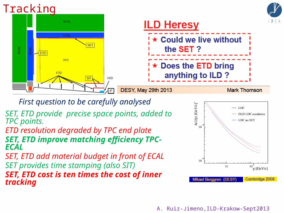
- First question to be carefully analysed
Tracking
A. Ruiz-Jimeno,ILD-Krakow-Sept2013
- First question to be carefully analysedSET, ETD provide precise space points, added to TPC points.ETD resolution degraded by TPC end plateSET, ETD improve matching efficiency TPC-ECALSET, ETD add material budget in front of ECALSET provides time stamping (also SIT)SET, ETD cost is ten times the cost of inner tracking
Tracking

A. Ruiz-Jimeno,ILD-Krakow-Sept2013
- First question to be carefully analysedSET, ETD provide precise space points, added to TPC points.ETD resolution degraded by TPC end plateSET, ETD improve matching efficiency TPC-ECALSET, ETD add material budget in front of ECALSET provides time stamping (also SIT)SET, ETD cost is ten times the cost of inner tracking
To answer the question it is needed to analyze it with a realistic ILD layout. Calorimeter people input is very
important
Tracking
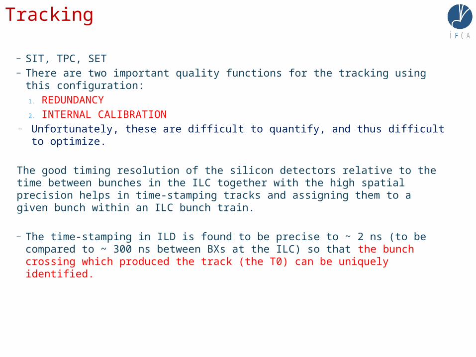
— SIT, TPC, SET— There are two important quality functions for the tracking using this
configuration:1. REDUNDANCY2. INTERNAL CALIBRATION
— Unfortunately, these are difficult to quantify, and thus difficult to optimize.
The good timing resolution of the silicon detectors relative to the time between bunches in the ILC together with the high spatial precision helps in time-stamping tracks and assigning them to a given bunch within an ILC bunch train.
— The time-stamping in ILD is found to be precise to ~ 2 ns (to be compared to ~ 300 ns between BXs at the ILC) so that the bunch crossing which produced the track (the T0) can be uniquely identified.
Tracking
A. Ruiz-Jimeno,ILD-Krakow-Sept2013
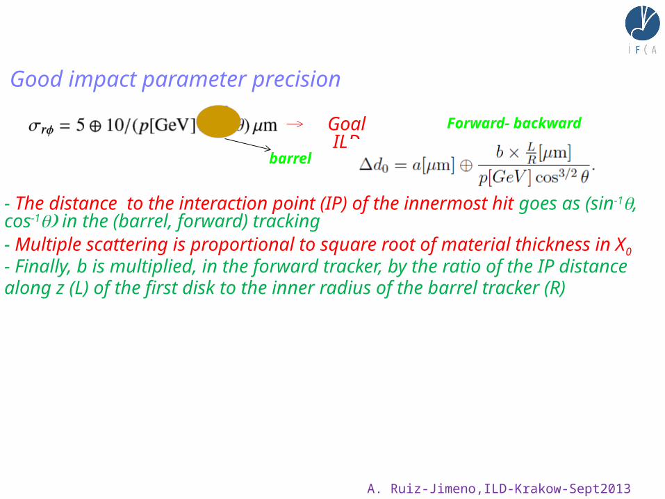
Good impact parameter precision
barrel
Goal ILD Forward- backward
- The distance to the interaction point (IP) of the innermost hit goes as (sin-1q, cos-
1 )q in the (barrel, forward) tracking- Multiple scattering is proportional to square root of material thickness in X0
- Finally, b is multiplied, in the forward tracker, by the ratio of the IP distance along z (L) of the first disk to the inner radius of the barrel tracker (R)

A. Ruiz-Jimeno,ILD-Krakow-Sept2013
Good impact parameter precision
barrel
Goal ILD Forward- backward
- The distance to the interaction point (IP) of the innermost hit goes as (sin-1q, cos-
1 )q in the (barrel, forward) tracking- Multiple scattering is proportional to square root of material thickness in X0
- Finally, b is multiplied, in the forward tracker, by the ratio of the IP distance along z (L) of the first disk to the inner radius of the barrel tracker (R)
Limited by the background near IPThe gap between barrel and end cap
limited by mechanics and services
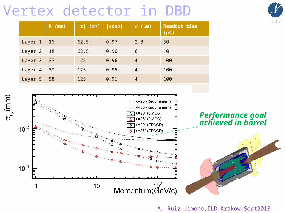
Vertex detector in DBDR (mm) |z| (mm) |cosq| s (mm) Readout time
(ms)
Layer 1 16 62.5 0.97 2.8 50
Layer 2 18 62.5 0.96 6 10
Layer 3 37 125 0.96 4 100
Layer 4 39 125 0.95 4 100
Layer 5 58 125 0.91 4 100
Layer 6 60 125 0.9 4 100
Performance goal achieved in barrel
A. Ruiz-Jimeno,ILD-Krakow-Sept2013
A. Ruiz-Jimeno,ILD-Krakow-Sept2013
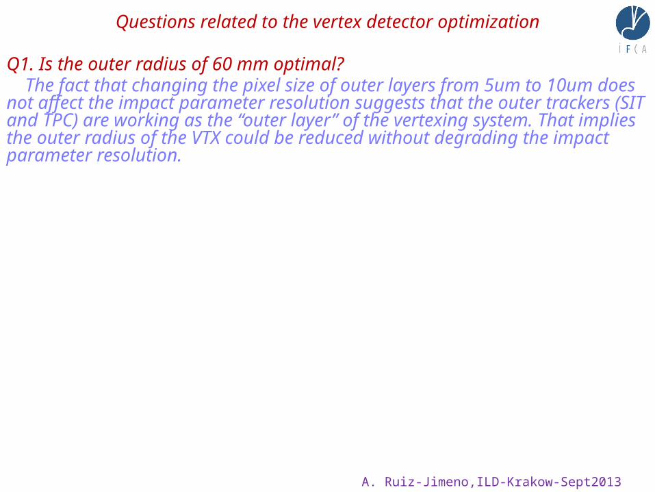
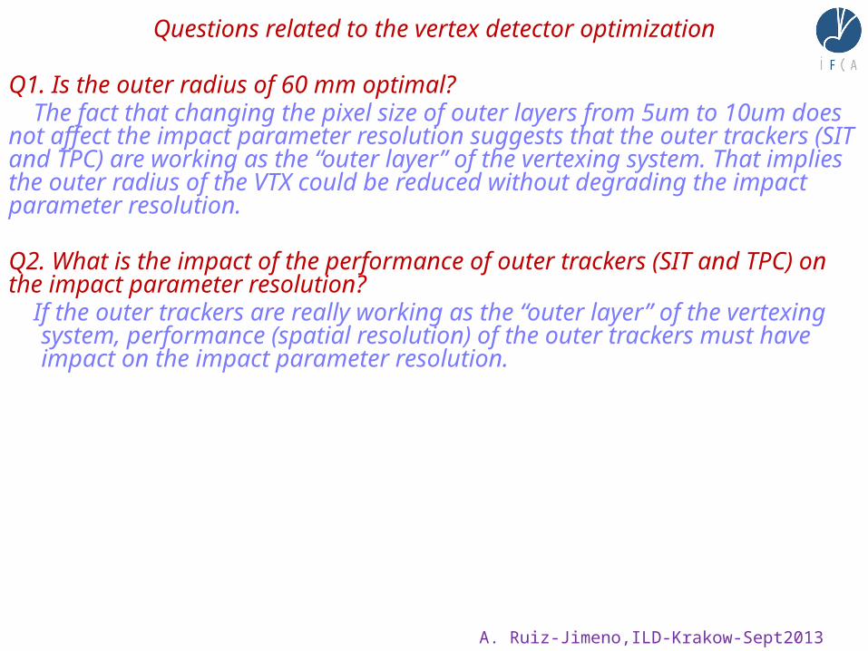
Questions related to the vertex detector optimization
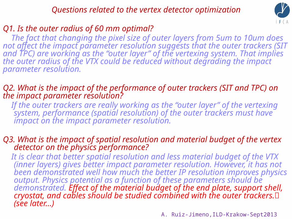
Q1. Is the outer radius of 60 mm optimal? The fact that changing the pixel size of outer layers from 5um to 10um does not affect the impact parameter resolution suggests that the outer trackers (SIT and TPC) are working as the “outer layer” of the vertexing system. That implies the outer radius of the VTX could be reduced without degrading the impact parameter resolution.
A. Ruiz-Jimeno,ILD-Krakow-Sept2013
Questions related to the vertex detector optimization
Q1. Is the outer radius of 60 mm optimal? The fact that changing the pixel size of outer layers from 5um to 10um does not affect the impact parameter resolution suggests that the outer trackers (SIT and TPC) are working as the “outer layer” of the vertexing system. That implies the outer radius of the VTX could be reduced without degrading the impact parameter resolution. Q2. What is the impact of the performance of outer trackers (SIT and TPC) on the impact parameter resolution? If the outer trackers are really working as the “outer layer” of the vertexing system,
performance (spatial resolution) of the outer trackers must have impact on the impact parameter resolution.
Q3. What is the impact of spatial resolution and material budget of the vertex detector
on the physics performance? It is clear that better spatial resolution and less material budget of the VTX (inner
layers) gives better impact parameter resolution. However, it has not been demonstrated well how much the better IP resolution improves physics output. Physics potential as a function of these parameters should be demonstrated. Effect of the material budget of the end plate, support shell, cryostat, and cables should be studied combined with the outer trackers. (see later…)

A. Ruiz-Jimeno,ILD-Krakow-Sept2013
Good impact parameter precision
1 GeV
100 GeV
Functional form, toy detector with 0,12% X0 per layer, 3 m spatial resolution in r f and z
Realistic material budget can degrade notoriously the impact
parameter resolution
Mainly vertex cables, services…
(not FTD)
JINST 8 T06001 2013

A. Ruiz-Jimeno,ILD-Krakow-Sept2013
Engineering challenges:
Beam pipe as thin as possible
Careful optimization of the services and support structures of the barrel vertex detector to avoid a.m.a.p. the line of sight between the IP and the
innermost disk
Routing of the barrel vertex detector cables and services over the end-cap

A. Ruiz-Jimeno,ILD-Krakow-Sept2013
Good pattern recognitionOCCUPANCY
FTD1 (eett) average
FTD1 (eett) peak
JINST 8 T06001 2013
Pixels of 25*25 mm2 in the most inner region allows robust pattern recognition for a readout time of 50 msec ( about 100 BX)

A. Ruiz-Jimeno,ILD-Krakow-Sept2013
Good pattern recognition
JINST 8 T06001 2013
Microstrip detectors in the forward tracker have radially oriented strips. To constraint the second coordinate with a low proportion of ghost hits, an stereo angle a of about
100 mrad will be used
100*100 mm2 sensors with 25 mm pitch
a= 100 mrad s(r) = 20 s (space point resolution of the detector)
Moderately precise r-measurements should be needed in all the forward tracking layers to have a robust pattern recognition

A. Ruiz-Jimeno,ILD-Krakow-Sept2013
More questions related to the vertex ( and tracker) detector optimization
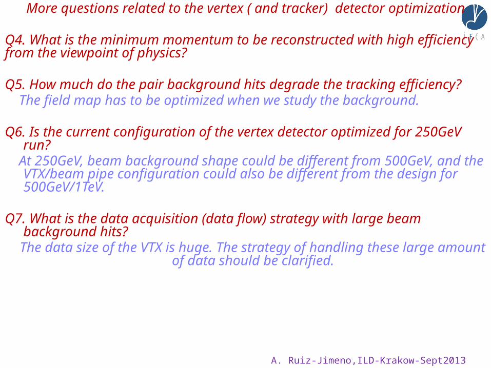
Q4. What is the minimum momentum to be reconstructed with high efficiency from the viewpoint of physics?

A. Ruiz-Jimeno,ILD-Krakow-Sept2013
More questions related to the vertex ( and tracker) detector optimization
Q4. What is the minimum momentum to be reconstructed with high efficiency from the viewpoint of physics? Q5. How much do the pair background hits degrade the tracking efficiency? The field map has to be optimized when we study the background.

A. Ruiz-Jimeno,ILD-Krakow-Sept2013
More questions related to the vertex ( and tracker) detector optimization
Q4. What is the minimum momentum to be reconstructed with high efficiency from the viewpoint of physics? Q5. How much do the pair background hits degrade the tracking efficiency? The field map has to be optimized when we study the background. Q6. Is the current configuration of the vertex detector optimized for 250GeV run? At 250GeV, beam background shape could be different from 500GeV, and the
VTX/beam pipe configuration could also be different from the design for 500GeV/1TeV.
Q7. What is the data acquisition (data flow) strategy with large beam background
hits? The data size of the VTX is huge. The strategy of handling these large amount of
data should be clarified.

A. Ruiz-Jimeno,ILD-Krakow-Sept2013
More questions related to the vertex ( and tracker) detector optimization
Q4. What is the minimum momentum to be reconstructed with high efficiency from the viewpoint of physics? Q5. How much do the pair background hits degrade the tracking efficiency? The field map has to be optimized when we study the background. Q6. Is the current configuration of the vertex detector optimized for 250GeV run? At 250GeV, beam background shape could be different from 500GeV, and the
VTX/beam pipe configuration could also be different from the design for 500GeV/1TeV.
Q7. What is the data acquisition (data flow) strategy with large beam background
hits? The data size of the VTX is huge. The strategy of handling these large amount of
data should be clarified. Does the ILD design provide robust tracking down to 6 degrees?
The CLIC answer: no!Redesign prompted by larger background (inner radius 1.5 cm → 3 cm)
2-disk pixel system extended to 3 double layers (See : Dannheim, Vos, Simulation studies for the layout of the vertex and tracking
regions of the CLIC detectors, LCD-2011-031)

A. Ruiz-Jimeno,ILD-Krakow-Sept2013
A FAST-TRACK OF THE FORWARD TRACKER STATUS ( more information on I.Vila and F. Arteche talks)
Instituto de Física de Cantabria (IFCA)
Instituto Tecnológico de Aragón (ITA)
Instituto de Física Corpuscular (IFIC)
Centro Nacional de Microelectrónica de Barcelona (CNM-IMB)Universidad de Barcelona (UB)
Instituto Nacional de Tecnicas Aeronauticas

A. Ruiz-Jimeno,ILD-Krakow-Sept2013
A FAST-TRACK OF THE FORWARD TRACKER STATUS ( more information on I.Vila and F. Arteche talks)
CONSIDERATIUM:
Most of the developments made could serve also for the barrel tracker system.
Anyway there are differences which should be considered in a realistic way
DESIDERATUM:
To reorganize the silicon tracker system as a unique system
Instituto de Física de Cantabria (IFCA)
Instituto Tecnológico de Aragón (ITA)
Instituto de Física Corpuscular (IFIC)
Centro Nacional de Microelectrónica de Barcelona (CNM-IMB)Universidad de Barcelona (UB)
Instituto Nacional de Tecnicas Aeronauticas

A. Ruiz-Jimeno,ILD-Krakow-Sept2013
FORWARD TRACKER STATUS
Baseline sensor: conventional microstrip sensor with integrated signal routing in a second metal layer.Baseline operational unit: petal (sensor+standard hybrid board(s) with readout, powering and data link circuitry.
R&D on future technologies ( see I. Vila talk)

(19)
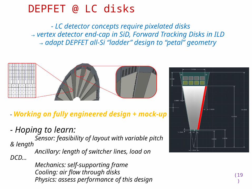
DEPFET @ LC disks
- LC detector concepts require pixelated disks → vertex detector end-cap in SiD, Forward Tracking Disks in ILD
→ adapt DEPFET all-Si “ladder” design to “petal” geometry
(19)
DEPFET @ LC disks
- LC detector concepts require pixelated disks → vertex detector end-cap in SiD, Forward Tracking Disks in ILD
→ adapt DEPFET all-Si “ladder” design to “petal” geometry
- Working on fully engineered design + mock-up- Hoping to learn:
Sensor: feasibility of layout with variable pitch & length
Ancillary: length of switcher lines, load on DCD...Mechanics: self-supporting frameCooling: air flow through disksPhysics: assess performance of this design

(20)
DEPFET @ LC disks, Material budget
Big leap wrt to LHC...Admittedly not a fair comparison
Material budget close to LC goal!!!
Integrate!– Amplification stage in sensor– Support structure in sensor
– Signal and power lines on sensor– Electronics on sensors

A. Ruiz-Jimeno,ILD-Krakow-Sept2013
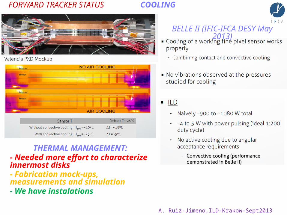
FORWARD TRACKER STATUS COOLING
BELLE II (IFIC-IFCA DESY May 2013)
A. Ruiz-Jimeno,ILD-Krakow-Sept2013
FORWARD TRACKER STATUS COOLING
BELLE II (IFIC-IFCA DESY May 2013)
THERMAL MANAGEMENT:- Needed more effort to characterize innermost disks- Fabrication mock-ups, measurements and simulation- We have instalations

A. Ruiz-Jimeno,ILD-Krakow-Sept2013
FORWARD TRACKER STATUS MECHANIC,CABLES
STUDY, PROGRESSING

A. Ruiz-Jimeno,ILD-Krakow-Sept2013
FORWARD TRACKER STATUS ASSEMBLING
STUDY, PROGRESSING

A. Ruiz-Jimeno,ILD-Krakow-Sept2013
FORWARD TRACKER STATUS FRONT END ELECTRONICS
In an initial phase. Much work to be doneThere are possible fall-back solutions

A. Ruiz-Jimeno,ILD-Krakow-Sept2013
FORWARD TRACKER STATUS POWER SYSTEM
WORK ONGOING SATISFACTORILY
See F.Arteche talk

A. Ruiz-Jimeno,ILD-Krakow-Sept2013
ALIGNMENT
Improved InfraRedtransparent microstripsdetectors for tracker alignment
WELL ADVANCED

A. Ruiz-Jimeno,ILD-Krakow-Sept2013
Real Time Structural and Environmental Monitoring
PROGRESSING

A. Ruiz-Jimeno,ILD-Krakow-Sept2013
Study to optimize design in a meaningful way:- samples: some signal with jets (tt), pair production and gg → hadrons (ILD MC team?)- design: provide alternative designs (Spanish LC network)- technology choice?: no, assume generic performance parameters in DBD- analysis: ad-hoc task force (joint venture of tracking software team + Spanish LC network?)
OPTIMIZATION
Lack of manpower

Costs
Costs— One way to reduce overall costs is to reduce the size
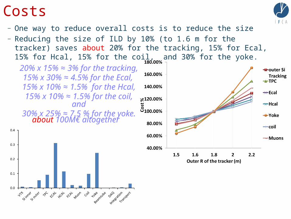
Costs— One way to reduce overall costs is to reduce the size — Reducing the size of ILD by 10% (to 1.6 m for the tracker) saves about 20% for
the tracking, 15% for Ecal, 15% for Hcal, 15% for the coil, and 30% for the yoke.
20% x 15% ≈ 3% for the tracking,15% x 30% ≈ 4.5% for the Ecal, 15% x 10% ≈ 1.5% for the Hcal,
15% x 10% ≈ 1.5% for the coil, and30% x 25% ≈ 7.5 % for the yoke.
about 100M€ altogether

Costs— 100M€. Does this make sense? Yes, of course, but...— What happens to the performance?
_ Vertexing ≈ unchanged._ Momentum resolution ≈ 20% worse._ Particle flow resolution ≈ ? (depends on the what happens to the Ecal
granularity)_ Coil is the size of CMS‘s, new tooling doesn‘t cost much, but experience with
4T?
—Bottom line: Mainly a question for Ecal granularity And performance
_ An old wisdom: don‘t save money in the wrong place

A. Ruiz-Jimeno,ILD-Krakow-Sept2013
TR@cking in ILDWe are approaching the goal !

BACKUP
A. Ruiz-Jimeno,ILD-Krakow-Sept2013
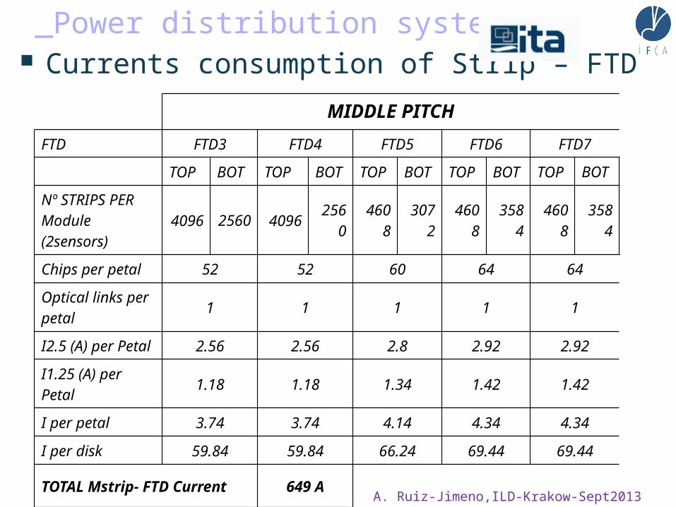
_Power distribution system Currents consumption of Strip – FTD
MIDDLE PITCH
FTD FTD3 FTD4 FTD5 FTD6 FTD7
TOP BOT TOP BOT TOP BOT TOP BOT TOP BOT
Nº STRIPS PER Module (2sensors) 4096 2560 4096 2560 4608 3072 4608 3584 4608 3584
Chips per petal 52 52 60 64 64
Optical links per petal 1 1 1 1 1
I2.5 (A) per Petal 2.56 2.56 2.8 2.92 2.92
I1.25 (A) per Petal 1.18 1.18 1.34 1.42 1.42
I per petal 3.74 3.74 4.14 4.34 4.34
I per disk 59.84 59.84 66.24 69.44 69.44
TOTAL Mstrip- FTD Current 649 A
A. Ruiz-Jimeno,ILD-Krakow-Sept2013

53
2.1 Powering schemes: DC-DC-based Power System
— Example (1/4 disk) : Power values per group:_ Routing inside each petal:
6 DC-DC converters 4 DC-DC (12V - 2.5V) 2 DC- DC (12V- 1.25V)
Max out current per DC-DC less than 3 A (low transients) Short cabling – Less than 1 meter (low voltage drop)
_ Outside petal (1 cable per ¼ disk) 1 DC-DC per power group
200V – 12V Max out current per DC-DC less than 3 A
Transients attenuated by the DC-DC_ Outside experiment
1 AC-DC per disk 400V 50 Hz – 200V DC
Max current per cable less than 1 A
[email protected], 2012 ILD Workshop, May 23th, Fokuaka University.

Powering schemes: Supercapacitor based PS— This power system is
based on :_ Supercapacitors
Pulse power _ LV regulators
Stabilize FEE voltage_ Current source
supercapacitor voltage controlled
— To absorb transients related to power pulsing system._ Keep transients locally
at FEE level.
[email protected], 2012 ILD Workshop, May 23th, Fokuaka University.

55
Powering schemes: Supercapacitor based PS
— Power values per ¼ disk (power group)_ Routing inside each petal
3 Regulators 2 REG (5V -2.5V) / 2.92 A Pk – 0.29A 1 REG (5V- 1.25V) / 1.42 A Pk – 0.15A
Max out current per petal (16 petals) – 4.34 A / 0.434A) Short cabling – Less than 1 meter (low voltage drop) ? 2 Supercapacitors per (1/4 disk) – C=75 F / V=5 V / Imax=18 A /Imin=2
_ Outside petal - ¼ disk 1 Cable per disk Max out current per cable around 2/3 A (defined by FEE)
_ Outside experiment 1 Current source per ¼ disk
IDC = 2/3 A
— A similar number of HV cable will be considered to keep the same granularity_ 1 HV cable and HV power unit per ¼ disk
[email protected], 2012 ILD Workshop, May 23th, Fokuaka University.

A. Ruiz-Jimeno,ILD-Krakow-Sept2013

A. Ruiz-Jimeno,ILD-Krakow-Sept2013
One module of each FTD disk will be composed by four petals ( 16 sensors) in order to reduce cables. For each module we will have eight LV 5/2.5 regulators, four LV 5/1.25 regulator and two supercapacitors. Each disk will be by a power system of 16 W. The power to two supercapacitors will be transmited usin an AWG 16 cable . The conexión
from the supercapacitors to the LV regulators will be done by and AWG16 cooper cable too. For each module we will have too one HV cable ( AWG25) and one
optical cable. So for each module there will bee four cooper cables with a total section of 3.03 mm2 and for each disk 16 cables with a total section of 12.12 mm2.
Per module we will have:2 LV cables ( AWG 16) for supercapacitors powering
2 HV cables (AWG 24) for sensors polarizing1 fiber optic for results transmision
In the next table can be seen the total numbre or cables and cooper section going
outside the FTD. Only is taking into account the ustrip FTD cables ( it must be added vertex, SIT and pixel FTD-s cables)
FTD3 FTD4 FTD5 FTD6 FTD7Fiber optic cable 4 8 12 16 20
Nº HV cables (AWG 24)
8 16 24 32 40
Nº LV cables ( AWG 16)
8 16 24 32 40
Total cooper section (mm2)
12.092 24.184 36.276 48.368 60.46