Embed Size (px)
Citation preview
1
A Robust Lyapunov’s De-modulator for Tracking ofSingle/Three-Phase Grid Voltage VariablesA. K. Verma, Member, IEEE, C. Subramanian, Member, IEEE, R. K. Jarial, Member, IEEE,
Pedro Roncero-Sanchez, Senior Member, IEEE, and U. Mohan Rao, Member, IEEE
Abstract—In this article, a robust Lyapunov demodulator(LD) based on orthogonal signal generation (OSG) approachfor single/three-phase application is proposed. Conventionally,LD is not capable of rejecting the DC-offset in the grid signal.Thus, an additional estimation loop is required which mayaffect the dynamic performance. Nevertheless, an application ofharmonically polluted grid voltage signal to LD may severelyaffect the steady-state performance of the estimated parameters.To address these issues, an enhanced LD based-OSG is proposed,wherein a moving average filter is incorporated in the LD–OSGstructure. Thus, rapid rejection of DC-offset and harmonics iseasily achieved without any additional loop. The proposed struc-ture may accurately estimate the fundamental in-phase and thequadrature components. However, these orthogonal componentsmay suffer from amplitude imbalance and errors in the phaseinformation under off-nominal frequency conditions. Addition-ally, the errors in the amplitude and the phase information areeliminated using an open-loop frequency deviation detector and afeed-forward curve fitting approach. The dynamic performanceof the proposed scheme has been validated by numerical andhardware studies. It is reported that, with the less sensitivitytoward phase angle jump and good immunity to fundamentalnegative sequence, the proposed scheme is a potential techniquefor synchronization of single/three-phase grid connected powerelectronic equipment.
Index Terms—Lyapunov demodulator, moving average filter(MAF), amplitude estimation, phase estimation, frequency esti-mation.
I. INTRODUCTION
W ITH the evolution of the smart grid, the improvementin the grid resilience and power quality relies on a good
control over grid connected converters (GCCs) [1], [2]. Thecontrol architecture of GCC is composed of well known gridsynchronization algorithms i.e. phase locked–loops (PLLs)and frequency locked–loops [3]–[14]. In general, an elevatedperformance of a control algorithm is achieved by analog ordigital signal conditioning units. With the pertinent digitalsignal processors, the robust performance of a control tech-nique relies on a fast removal of the noise and the harmoniccomponents [4]. Thus, demanding the need for research onimmunity based digital filtering techniques [5]. The optimizedfiltering techniques often applied for the developement ofbetter control architecture of GCCs are reported in [6]–[8].
Synchronous reference frame (SRF) PLL usually providesa good estimate of the grid attributes. However, the SRF-PLL alone is incapable of handling the grid disturbances (i.e.DC-offset, harmonics and the fundamental negative sequence(FNS)). It is well known that the SRF-PLL is a type-2 systemand posses low-pass filtering capability. Importantly, simulta-neous rejection of the DC-offset and harmonics may impose amajor challenge for the detection of the grid voltage attributes
for power system applications [8]. To overcome this issue, in-loop and pre-loop filters are deployed to improve the trackingability of the SRF-PLL [8], [9]. With the inclusion of a specifictype of filtering technique, the stability margin, controllertuning, and trade-off in the response time are challenging forSRF–PLLs [10], [11]. Nevertheless, the non-adaptive pre-loopfiltering methods demostrate fast dyanmic response when com-pared to in-loop filtering methods. However, erroneous resultsin the estimate of amplitude and the phase information remainchallenging irrespective to the choice of control algorithm[12]. Thus, error correction units are required to achieve zerosteady-state error in the estimate of the fundamental amplitudeand the phase information.
It is to be recalled that the DC-offset and FNS componentsare the main reasons for double frequency oscillations in theestimated parameters obtained from a grid synchronizationalgorithm [10]–[14]. The orthgonal signal generation (OSG)filters along with an instantaneous symmetrical componentmethod are capable of rejecting the DC-offset and FNScomponents [13], [14]. Thus, there is need to explore improvedand accurate phase tracking algorithms with a good dynamicbehavior and negligible steady-state errors accompanied byhigh immunity to grid disturbances.
The OSG based on demodulation of the grid voltage signalis a potential approach to estimate the grid attributes [15]–[24]. The demodulation of a single-phase signal is achievedby multiplying fixed frequency unit orthogonal signals thatprovide rotating reference (dq) frame components, as reportedin [15], [16]. However, the presence of harmonics and DC-offset components will induce full cycle and even harmonicscomponents in the demodulated components [16]. Thus, theleast-squares-Kalman filter based demodulation approach iseqquiped with an ability to reject the negative effects ofharmonics [17], [18]. Nevertheless, this approach is compu-tationally complex owing to the higher-order finite impulseresponse filters. On the other hand, low pass filter (LPFs)based schemes involve in phase errors under off-nominal fre-quency conditions [16]–[19]. Thus, a computationally efficientinfinite impulse response-LPF based demodulation schemewith minimum phase error and an improved response timeis reported in [20]. The predictive filtering in conjuctionwith moving average filters (MAFs) may be deployed tominimize errors in the phase information [21]. On the otherhand, improved frequency adaptive filtered-sequence MAF-PLL may avoid predictive filters for accurate extraction of thephase information [22]. The simplest open-loop demodulationbased phase error compensation technique is reported in [23].However, a proper rejection of the DC-offset and harmonicsunder off-nominal frequency condition is challenging with
2
this approach. Thus, a grid voltage demodulation techniqueas reported in [24] may be adopted with improved off-nominal harmonic and the DC-offset rejection capabilities.However, the DSC operator involved in the pre-filtering stageis responsible for elevation of the noise signal present in thegrid signal. Importantly, a good dynamic response may beachieved with this technique for grid synchronization pur-pose. Nevertheless, the quest for improved orthogonal signalgenerators are still in demand. Also, the open-loop frequencyestimators when combined with improved OSGs may help inattaining improved robustness, memory storage, steady-stateaccuracy, and dynamic performance. It is expected to have aninvestigation regarding the combination of new OSG structuresalong with the open-loop frequency estimation algorithmsfor achieving better accuracy and robust performance underadverse grid voltage conditions. It is well known that the open-loop frequency estimators performs well once the fundamentalgrid voltage signal is obtained. Thus, the pre-filters (OSGs)are responsible for strengthening the overall robustness of anysynchronization scheme.
An effective approach with which to perform OSG relieson non-linear control theory [25], [26] based Lyapunov de-modulation [27]–[29]. The analysis of Lyapunov based PLL(L–PLL) is reported in [27] to estimate the grid attributes.However, L–PLL is not immune to the DC-offset. To addressthis issue, an additional DC-offset rejection loop may bedeployed with a trade-off in the response time [28], [29].Under off-nominal frequency conditions, the improved L-PLL[29] is incapable of rejecting harmonics properly. Thus, thechallenges with regard to the performance improvement areaddressed, in this article, as follows: A non-adaptive enhancedLyapunov demodulator-based-OSG (ELD–OSG) is proposed.The possibility of rejecting the DC-offset and harmonics isenhanced by incorporating MAFs in LD–OSG structure. Underoff-nominal frequency conditions, steady-state errors in theestimated amplitude and phase information are eliminatedthrough an online regression method. For this purpose, anopen-loop frequency detector is considered owing to its su-periority over the PLL. The salient features of the proposedscheme are as follows:• Good immunity to harmonics, DC-offset, and FNS.• Improved and stable dynamic behavior.• Improved steady-state accuracy.• Reduced tuning efforts owing to the avoidance of fre-
quency and phase feedback loops• Simple error compensation approach for amplitude and
phase estimation.
II. CONVENTIONAL LYAPUNOV DEMODULATOR
The Laypunov demodulator (LD) [22] is a non-linear ap-proach that allows to reconstruct a single-phase grid voltagesignal from its dq−frame (i.e. direct (vd) axis and quadrature(vq) axis) components, as explained below:
v(t) = A cos(φ) sin(ωnot) +A sin(φ) cos(ωnot)
= vq S1 + vd C1 (1)
where, S1 = sin(ωnot), C1 = cos(ωnot), vq = A cos(φ),vd = Asin(φ), ωno is the nominal angular grid frequency, and
φ is the initial phase angle. The estimate of v(t) is expressedas follows,
v(t) = vq S1 + vd C1 (2)
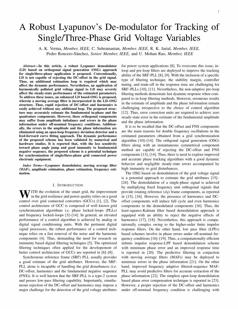
where, the estimate of the states i.e. vq and vd are denotedby vq and vd, respectively. The accurate estimation of thedq−frame components i.e. vq and vd may be achieved byimplementing the LD, as shown in Fig 1. The re-constructionof the fundamental orthogonal signals (vα and vβ) may beachieved by an inverse Park’s Transformation (IPT).
Fig. 1. General block diagram of Lyapunov’s demodulator-based-OSG.
A. Lyapunov’s Estimation LawThe Lyapunov’s estimation law relies on the demodulation
of the error (e) between v and v which is given below:˙vq(t) = σ sin(ωnot) (v − v) = σ sin(ωnot) e (3)˙vd(t) = σ cos(ωnot) (v − v) = σ cos(ωnot) e (4)
where, the time derivatives of state variables (vq and vd) are˙vq and ˙vq , respectively and σ represents a constant gain. Thegeneralized state space model is expressed as follows,
˙x = σ H e (5)v = HT x (6)
where, H = [sin(ωnot), cos(ωnot)]T and x = [vq, vd]
T .
B. Stability and Convergence of State-Space VectorAs reported in [25], [26], and [28], the stability of the
Lyapunov estimation law is based on Kalman-Yakubovich-Popov and Meyer-Kalman-Yakubovich Lemmas along withthe strictly positive real Lyapunov design approach. Thus, theappropriate choice of Lyapunov like function (VLP ) is whenthe time derivative of VLP is non-positive, i.e. VLP ≤ 0.This ensures guaranteed boundedness as well as the stability(e, x, ˙x) as per [25]. In addition, the signal vector H followsthe persistent excitation (PE) property if there exist αo, α1,and To > 0 such that,
α1I ≥∫ t+To
t
H(τ)HT (τ)dτ ≥ αoI (7)
Thus, unboundedness of signal vector H is not the case forLyapunov estimation law [25], [28]. In the time interval [t, t+T0], the integral of the matrix H(τ)HT (τ) is uniformly positivedefinite [25], [26]. Hence, the exponential convergence of xto x is ensured.
3
III. PROPOSED ENHANCED LD–OSG BASED SCHEME
In this section, the analysis of the proposed enhanced LD(ELD) based OSG is investigated for single/three-phase gridattributes tracking. The major challenges with regard to theelimination of DC-offset and the harmonics are discussed. Un-der off-nominal frequency deviations, the steady-state outputof ELD–OSG will be erroneous in regard to the fundamentalamplitude and phase angle information. Thus, a computation-ally efficient open-loop estimation of the frequency deviationis presented to eliminate the aforementioned errors.
A. Error Boundedness
As discussed, the error term in (3) and (4) may be expressedas follows:
e = v − v = vq S1 + vd C1 − vq S1 − vd C1 (8)
The errors in the estimation may be represented as follows:
vq = vq − vq (9)vd = vd − vd (10)
Substituting (9) and (10) in (8), the error (e) is,
e = vq S1 + vd C1 (11)
Thus, a Laypunov’s like function is constructed as follows:
VLP (t) =v2q (t) + v2d(t)
2(12)
The time derivative of (12) yields.
VLP (t) = vq ˙vq + vd ˙vd (13)
where, ˙vq = − ˙vq and ˙vd = − ˙vd. Similarly, the time derivativeof estimation errors may be expressed as follows:
˙vq = −σS1e (14)˙vd = −σC1e (15)
Thus, VLP (t) may be rewritten as follows:
VLP (t) = −σ (vq S1 + vd C1) e = −σ e2 (16)
According to PE property [25],[26], for positive values of σ >0, VLP (t) ≤ 0 must hold. Thus, it may be concluded that,
limt→∞
= vq = vq (17)
limt→∞
= vd = vd (18)
From (17) and (18), the unknowns vq and vd are estimatedwithout any steady-state error.
B. Effect of the DC-Offset
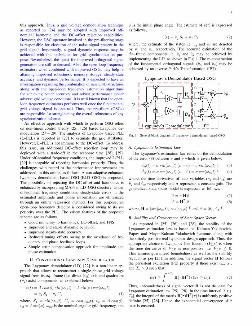
The Lyapunov’s estimation law is sensitive to DC-offsetcomponent present in the grid signal, as discussed in [28],[29]. In order to deal with this issue, a third state may beadded representing the DC-offset (Vo) [28]. In addition, aconstant element i.e. 1 is added to the signal vector (H) asH = [sin(ωnot), cos(ωnot), 1]T and a tuning gain σ1 maybe introduced to update the law for rejection of DC-offset, asreported in [29]. In Fig. 2, the implementation of the DC-offset
Fig. 2. Implementation of DC-offset rejection loop.
rejection loop is depicted. From [28], [29], the suitable choicefor σ and σ1 is, σ = 8fno and σ1 = fno where, fno is thenominal frequency i.e. 50 Hz. As σ1 = σ/8, it is understoodthat the convergence rate of Vo state may affect the overalldynamic response. Thus, a grid voltage signal contaminatedwith a DC-offset is considered as follows:
v(t) = A sin(ωnot+ φ) + Vo = vq S1 + vd C1 + Vo (19)
Using (8) and (19), the error (e1) in case of a DC-offset is,
e1 = e+ Vo = vq S1 + vd C1 − vq S1 − vd C1 + Vo (20)
Using (3) and (4), e1 may be demodulated to obtain ˙vq and˙vd in terms of e and Vo as shown below:
˙vq = σS1e1 = σ S1 e+ σ Vo S1 (21)˙vd = σC1e1 = σ C1 e+ σ Vo C1 (22)
From (21) and (22), it may be observed that Vo will becomea full cycle component with an oscillating frequency of fno.To deal with this issue, a moving average filter (MAF) [10],[21] may be deployed in LD–OSG structure, as shown inFig. 3. The window length (Tw) of MAF is equivalent to one
Fig. 3. Improved orthogonal signal generation based on LD.
fundamental period i.e. Tw = Tno, where Tno = 1/fno andfno = 50 Hz. In Fig. 3, the filtered dq-frame components i.e.vq and vd are fed to IPT to obtain vα and vβ . In order tounderstand the effect of MAF in the ELD–OSG structure, afrequency response plot is provided in Fig. 4.
Fig. 4. Frequency response plot for ELD-based-OSG.
4
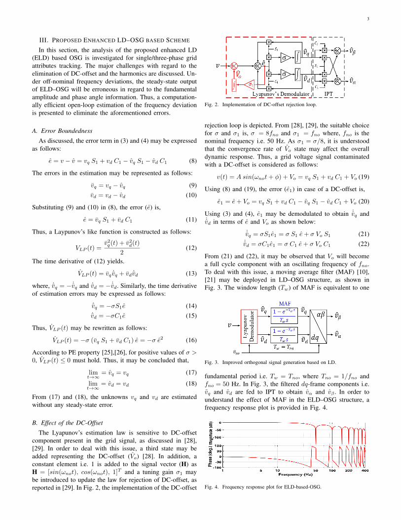
It may be observed that the proposed structure behaves as acomb filter which may effectively reject the DC-offset compo-nent. In a simulation environment, the fundamental amplitude(i.e. A =
√v2α + v2β ) is estimated in the presence of 10% DC-
offset with 50% voltage sag in the grid signal, as shown inFig. 5. It may be observed that the ELD–OSG structure posses
Fig. 5. Dynamic performance comparison in case of a DC-Offset in gridsignal.
a good DC-offset rejection capability and takes approximatelytwo times of fundamental cycle (i.e. 40 ms) to estimate theamplitude. The ELD–OSG structure demonstrates good andstable dynamic performance as compared to the LD–OSGstructure.
C. Small Signal Model and Effect of Harmonics
In this section, the small signal model of the LD is revisitedto explore the type of filtering capability associated withthe LD, as shown in Fig. 6 wherein D1 denotes the outputdisturbance.
Fig. 6. Small signal model of the LD.
It may be inferred that the error term is subdivided into twoequal parts between the input states (vd and vq) to the outputstates (vd and vq). The simplified transfer function relationshipis as follows,
Vd(s)
Vd(s)=
1(sωc
)+ 1
(23)
Vq(s)
Vq(s)=
1(sωc
)+ 1
(24)
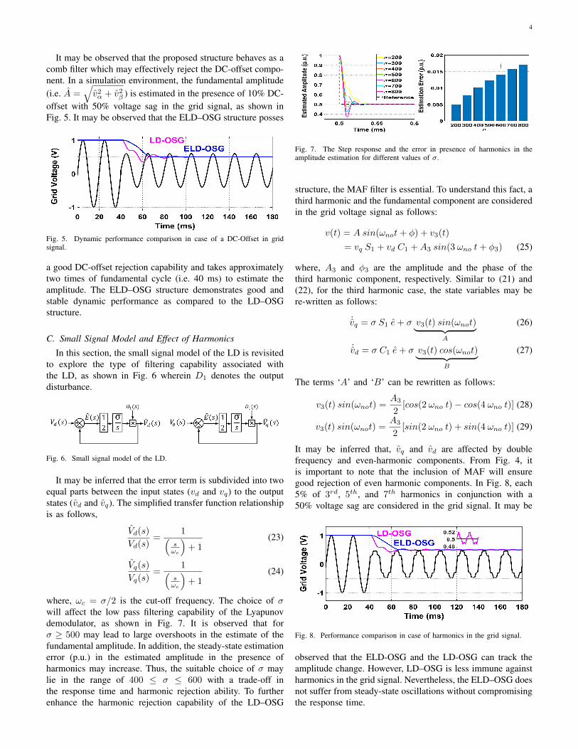
where, ωc = σ/2 is the cut-off frequency. The choice of σwill affect the low pass filtering capability of the Lyapunovdemodulator, as shown in Fig. 7. It is observed that forσ ≥ 500 may lead to large overshoots in the estimate of thefundamental amplitude. In addition, the steady-state estimationerror (p.u.) in the estimated amplitude in the presence ofharmonics may increase. Thus, the suitable choice of σ maylie in the range of 400 ≤ σ ≤ 600 with a trade-off inthe response time and harmonic rejection ability. To furtherenhance the harmonic rejection capability of the LD–OSG
Fig. 7. The Step response and the error in presence of harmonics in theamplitude estimation for different values of σ.
structure, the MAF filter is essential. To understand this fact, athird harmonic and the fundamental component are consideredin the grid voltage signal as follows:
v(t) = A sin(ωnot+ φ) + v3(t)
= vq S1 + vd C1 +A3 sin(3 ωno t+ φ3) (25)
where, A3 and φ3 are the amplitude and the phase of thethird harmonic component, respectively. Similar to (21) and(22), for the third harmonic case, the state variables may bere-written as follows:
˙vq = σ S1 e+ σ v3(t) sin(ωnot)︸ ︷︷ ︸A
(26)
˙vd = σ C1 e+ σ v3(t) cos(ωnot)︸ ︷︷ ︸B
(27)
The terms ‘A’ and ‘B’ can be rewritten as follows:
v3(t) sin(ωnot) =A3
2[cos(2 ωno t)− cos(4 ωno t)] (28)
v3(t) sin(ωnot) =A3
2[sin(2 ωno t) + sin(4 ωno t)] (29)
It may be inferred that, vq and vd are affected by doublefrequency and even-harmonic components. From Fig. 4, itis important to note that the inclusion of MAF will ensuregood rejection of even harmonic components. In Fig. 8, each5% of 3rd, 5th, and 7th harmonics in conjunction with a50% voltage sag are considered in the grid signal. It may be
Fig. 8. Performance comparison in case of harmonics in the grid signal.
observed that the ELD-OSG and the LD-OSG can track theamplitude change. However, LD–OSG is less immune againstharmonics in the grid signal. Nevertheless, the ELD–OSG doesnot suffer from steady-state oscillations without compromisingthe response time.
5
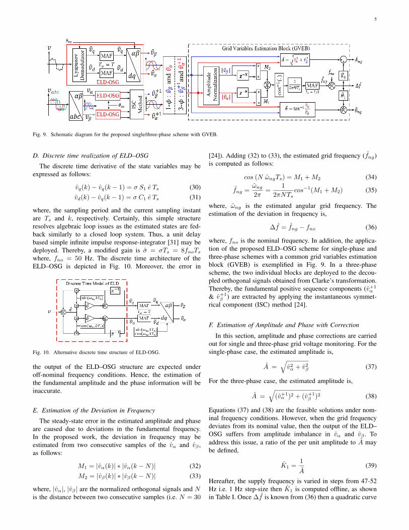
Fig. 9. Schematic diagram for the proposed single/three-phase scheme with GVEB.
D. Discrete time realization of ELD–OSG
The discrete time derivative of the state variables may beexpressed as follows:
vq(k)− vq(k − 1) = σ S1 e Ts (30)vd(k)− vq(k − 1) = σ C1 e Ts (31)
where, the sampling period and the current sampling instantare Ts and k, respectively. Certainly, this simple structureresolves algebraic loop issues as the estimated states are fed-back similarly to a closed loop system. Thus, a unit delaybased simple infinite impulse response-integrator [31] may bedeployed. Thereby, a modified gain is σ = σTs = 8fnoTswhere, fno = 50 Hz. The discrete time architecture of theELD–OSG is depicted in Fig. 10. Moreover, the error in
Fig. 10. Alternative discrete time structure of ELD-OSG.
the output of the ELD–OSG structure are expected underoff-nominal frequency conditions. Hence, the estimation ofthe fundamental amplitude and the phase information will beinaccurate.
E. Estimation of the Deviation in Frequency
The steady-state error in the estimated amplitude and phaseare caused due to deviations in the fundamental frequency.In the proposed work, the deviation in frequency may beestimated from two consecutive samples of the vα and vβ ,as follows:
M1 = |vα(k)| ∗ |vα(k −N)| (32)M2 = |vβ(k)| ∗ |vβ(k −N)| (33)
where, |vα|, |vβ | are the normalized orthogonal signals and Nis the distance between two consecutive samples (i.e. N = 30
[24]). Adding (32) to (33), the estimated grid frequency (fng)is computed as follows:
cos (N ωngTs) = M1 +M2 (34)
fng =ωng2π
=1
2πNTscos−1(M1 +M2) (35)
where, ωng is the estimated angular grid frequency. Theestimation of the deviation in frequency is,
∆f = fng − fno (36)
where, fno is the nominal frequency. In addition, the applica-tion of the proposed ELD–OSG scheme for single-phase andthree-phase schemes with a common grid variables estimationblock (GVEB) is exemplified in Fig. 9. In a three-phasescheme, the two individual blocks are deployed to the decou-pled orthogonal signals obtained from Clarke’s transformation.Thereby, the fundamental positive sequence components (v+1
α
& v+1β ) are extracted by applying the instantaneous symmet-
rical component (ISC) method [24].
F. Estimation of Amplitude and Phase with Correction
In this section, amplitude and phase corrections are carriedout for single and three-phase grid voltage monitoring. For thesingle-phase case, the estimated amplitude is,
A =√v2α + v2β (37)
For the three-phase case, the estimated amplitude is,
A =√
(v+1α )2 + (v+1
β )2 (38)
Equations (37) and (38) are the feasible solutions under nom-inal frequency conditions. However, when the grid frequencydeviates from its nominal value, then the output of the ELD–OSG suffers from amplitude imbalance in vα and vβ . Toaddress this issue, a ratio of the per unit amplitude to A maybe defined,
K1 =1
A(39)
Hereafter, the supply frequency is varied in steps from 47-52Hz i.e. 1 Hz step-size then K1 is computed offline, as shownin Table I. Once ∆f is known from (36) then a quadratic curve
6
TABLE ISIMULATED DATA FOR AMPLITUDE AND PHASE CORRECTION FACTOR
∆f (Hz) -3 -2 -1 0 1 2
θ1 (rad.) -0.2255 -0.141 -0.0572 0.0262 0.1092 0.192
K1 0.9768 0.9829 0.990786 1 1.0107 1.0231
fitting method is applied online to update K1 as follows:
K1 = 0.0008 (∆f)2 + 0.01 (∆f) + 1 (40)
The correct estimated amplitude (Ang) is,
Ang = K1
√v2α + v2β = K1A (41)
From (41), it can be inferred that if A is compensated correctly,then Ang → 1. Similarly, the phase angle information for thesingle-phase case is estimated as follows:
θ = arctan
(vαvβ
)(42)
For the three-phase case, the estimated phase is,
θ = arctan
(v+1α
v+1β
)(43)
The error in the phase information is denoted by θ1 whichmay be obtained by subtracting the artificially generated rampphase angle (θt) from θ i.e. θ1 = θt − θ. Similar to theprocedure followed in the amplitude correction case, for everystep change in the supply frequency θ1 is noted offline, asshown in Table I. Using (36), θ1 is expressed in terms of ∆fwhich may be updated through an online linear regressionmethod as expressed below:
θ1 = 0.0835(∆f) + 0.0257 (44)
The actual phase angle information is,
θng = θ + θ1 (45)
It may be understood that, if θ is correctly compensated thenθng → θt. Similarly, the correction factors for the three-phasecase in GVEB remain unchanged as shown in Fig. 9, only thefilter configuration needs to be changed.
IV. NUMERICAL RESULTS
The performance of the proposed ELD–OSG scheme iscompared with LD–PLL [29] in MATLAB/ Simulink envi-ronment. The simulation parameters are as follows: 1) gridvoltage: 1 p.u., 50 Hz, and sampling frequency of 12 kHz; 2)LD–PLL: σ = 400, σ1 = 50, kp = 5000; and 3) ELD–OSGscheme: σ = 600 thus σ = 0.05 and N = 30. The followingtwo test cases are considered: 1) single-phase (off-nominalcondition) and three-phase (unbalance, unequal DC-offset, andfrequency drift).
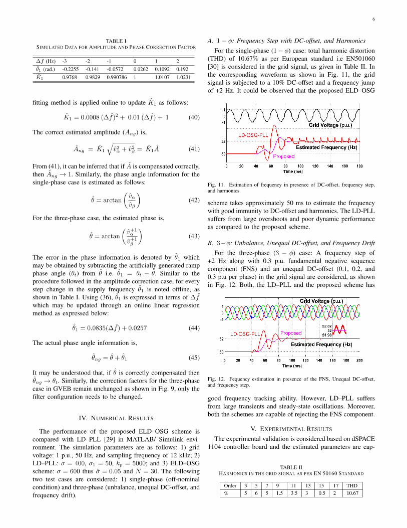
A. 1− φ: Frequency Step with DC-offset, and Harmonics
For the single-phase (1− φ) case: total harmonic distortion(THD) of 10.67% as per European standard i.e EN501060[30] is considered in the grid signal, as given in Table II. Inthe corresponding waveform as shown in Fig. 11, the gridsignal is subjected to a 10% DC-offset and a frequency jumpof +2 Hz. It could be observed that the proposed ELD–OSG
Fig. 11. Estimation of frequency in presence of DC-offset, frequency step,and harmonics.
scheme takes approximately 50 ms to estimate the frequencywith good immunity to DC-offset and harmonics. The LD-PLLsuffers from large overshoots and poor dynamic performanceas compared to the proposed scheme.
B. 3−φ: Unbalance, Unequal DC-offset, and Frequency Drift
For the three-phase (3 − φ) case: A frequency step of+2 Hz along with 0.3 p.u. fundamental negative sequencecomponent (FNS) and an unequal DC-offset (0.1, 0.2, and0.3 p.u per phase) in the grid signal are considered, as shownin Fig. 12. Both, the LD–PLL and the proposed scheme has
Fig. 12. Fequency estimation in presence of the FNS, Unequal DC-offset,and frequency step.
good frequency tracking ability. However, LD–PLL suffersfrom large transients and steady-state oscillations. Moreover,both the schemes are capable of rejecting the FNS component.
V. EXPERIMENTAL RESULTS
The experimental validation is considered based on dSPACE1104 controller board and the estimated parameters are cap-
TABLE IIHARMONICS IN THE GRID SIGNAL AS PER EN 50160 STANDARD
Order 3 5 7 9 11 13 15 17 THD% 5 6 5 1.5 3.5 3 0.5 2 10.67
7
tured on a 16 channel scopecorder (DL-750). The performanceof the ELD–OSG scheme is compared with the LD–PLL [29].The experimental parameters for the algorithms are similar tothe numerical results. To understand the significance of theELD–OSG, a single-phase and a three-phase variant of theproposed ELD–OSG scheme are provided. Importantly, twocritical test conditions are considered for single and three-phase case. Thereby, the dynamic performance improvementmay be observed at nominal and off-nominal frequency con-ditions.
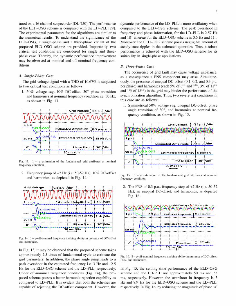
A. Single-Phase Case
The grid voltage signal with a THD of 10.67% is subjectedto two critical test conditions as follows:
1. 50% voltage sag, 10% DC-offset, 30◦ phase transitionand harmonics at nominal frequency condition i.e. 50 Hz,as shown in Fig. 13.
Fig. 13. 1 − φ estimation of the fundamental grid attributes at nominalfrequency condition.
2. Frequency jump of +2 Hz (i.e. 50-52 Hz), 10% DC-offsetand harmonics, as depicted in Fig. 14.
Fig. 14. 1−φ off-nominal frequency tracking ability in presence of DC-offsetand harmonics.
In Fig. 13, it may be observed that the proposed scheme takesapproximately 2.5 times of fundamental cycle to estimate thegrid parameters. In addition, the phase angle jump leads to apeak overshoot in the estimated frequency i.e. 3 Hz and 12.5Hz for the ELD–OSG scheme and the LD–PLL, respectively.Under off-nominal frequency conditions (Fig. 14), the pro-posed scheme posses a better harmonic rejection capability ascompared to LD–PLL. It is evident that both the schemes arecapable of rejecting the DC-offset component. However, the
dynamic performance of the LD–PLL is more oscillatory whencompared to the ELD–OSG scheme. The peak overshoot infrequency and phase information, for the LD–PLL is 2.57 Hzand 18◦ whereas for the ELD–OSG scheme is 0.6 Hz and 11◦.Moreover, the ELD–OSG scheme posses negligible amount ofsteady-state ripples in the estimated quantities. Thus, a robustperformance is achieved with the ELD–OSG scheme for itssuitability in single-phase applications.
B. Three-Phase Case
The occurrence of grid fault may cause voltage unbalance,as a consequence a FNS component may arise. Simultane-ously, the presence of unequal DC-offset (0.1, 0.2, and 0.3 p.u.per phase) and harmonics (each 5% of 5th and 7th, 3% of 11th
and 1% of 13th) in the grid may hinder the performance of thesynchronization algorithm. Thus, two severe test conditions inthis case are as follows:
1. Symmetrical 50% voltage sag, unequal DC-offset, phaseangle transition of 30◦, and harmonics at nominal fre-quency condition, as shown in Fig. 15.
Fig. 15. 3 − φ estimation of the fundamental grid attributes at nominalfrequency condition.
2. The FNS of 0.3 p.u., frequency step of +2 Hz (i.e. 50-52Hz), an unequal DC-offset, and harmonics, as depictedFig. 16.
Fig. 16. 3−φ off-nominal frequency tracking ability in presence of DC-offset,FNS, and harmonics.
In Fig. 15, the settling time performance of the ELD–OSGscheme and the LD-PLL are approximately 50 ms and 55ms, respectively. However, the overshoot in frequency is 3Hz and 8.9 Hz for the ELD–OSG scheme and the LD–PLL,respectively. In Fig. 16, by reducing the magnitude of phase ‘a’
8
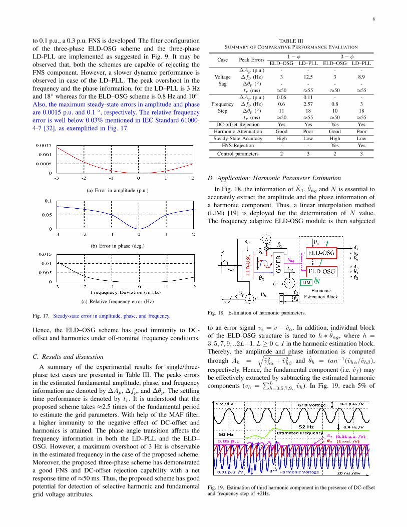
to 0.1 p.u., a 0.3 p.u. FNS is developed. The filter configurationof the three-phase ELD-OSG scheme and the three-phaseLD-PLL are implemented as suggested in Fig. 9. It may beobserved that, both the schemes are capable of rejecting theFNS component. However, a slower dynamic performance isobserved in case of the LD–PLL. The peak overshoot in thefrequency and the phase information, for the LD–PLL is 3 Hzand 18◦ whereas for the ELD–OSG scheme is 0.8 Hz and 10◦.Also, the maximum steady-state errors in amplitude and phaseare 0.0015 p.u. and 0.1 ◦, respectively. The relative frequencyerror is well below 0.03% mentioned in IEC Standard 61000-4-7 [32], as exemplified in Fig. 17.
(a) Error in amplitude (p.u.)
(b) Error in phase (deg.)
(c) Relative frequency error (Hz)
Fig. 17. Steady-state error in amplitude, phase, and frequency.
Hence, the ELD–OSG scheme has good immunity to DC-offset and harmonics under off-nominal frequency conditions.
C. Results and discussion
A summary of the experimental results for single/three-phase test cases are presented in Table III. The peaks errorsin the estimated fundamental amplitude, phase, and frequencyinformation are denoted by ∆Ap, ∆fp, and ∆θp. The settlingtime performance is denoted by tr. It is understood that theproposed scheme takes ≈2.5 times of the fundamental periodto estimate the grid parameters. With help of the MAF filter,a higher immunity to the negative effect of DC-offset andharmonics is attained. The phase angle transition affects thefrequency information in both the LD–PLL and the ELD–OSG. However, a maximum overshoot of 3 Hz is observablein the estimated frequency in the case of the proposed scheme.Moreover, the proposed three-phase scheme has demonstrateda good FNS and DC-offset rejection capability with a netresponse time of ≈50 ms. Thus, the proposed scheme has goodpotential for detection of selective harmonic and fundamentalgrid voltage attributes.
TABLE IIISUMMARY OF COMPARATIVE PERFORMANCE EVALUATION
Case Peak Errors1 − φ 3 − φ
ELD–OSG LD–PLL ELD–OSG LD–PLL
VoltageSag
∆Ap (p.u.) - - - -∆fp (Hz) 3 12.5 3 8.9∆θp (◦) - - - -tr (ms) ≈50 ≈55 ≈50 ≈55
FrequencyStep
∆Ap (p.u.) 0.06 0.11 - -∆fp (Hz) 0.6 2.57 0.8 3∆θp (◦) 11 18 10 18tr (ms) ≈50 ≈55 ≈50 ≈55
DC-offset Rejection Yes Yes Yes YesHarmonic Attenuation Good Poor Good PoorSteady-State Accuracy High Low High Low
FNS Rejection - - Yes Yes
Control parameters 2 3 2 3
D. Application: Harmonic Parameter Estimation
In Fig. 18, the information of K1, θng and N is essential toaccurately extract the amplitude and the phase information ofa harmonic component. Thus, a linear interpolation method(LIM) [19] is deployed for the determination of N value.The frequency adaptive ELD-OSG module is then subjected
Fig. 18. Estimation of harmonic parameters.
to an error signal ve = v − vα. In addition, individual blockof the ELD-OSG structure is tuned to h ∗ θng , where h =3, 5, 7, 9, ..2L+1, L ≥ 0 ∈ I in the harmonic estimation block.Thereby, the amplitude and phase information is computedthrough Ah =
√v2hα + v2hβ and θh = tan−1(vhα/vhβ),
respectively. Hence, the fundamental component (i.e. vf ) maybe effectively extracted by subtracting the estimated harmoniccomponents (vh =
∑Lh=3,5,7,9.. vh). In Fig. 19, each 5% of
Fig. 19. Estimation of third harmonic component in the presence of DC-offsetand frequency step of +2Hz.
9
3rd, 5th, 7th, and DC-offset along with a step change of+2 Hz in the supply frequency are considered in the gridsignal. It may be observed that the third harmonic componentis accurately estimated within 2.5 times of the fundamentalcycles.
E. Comparison with Other Synchronization Schemes
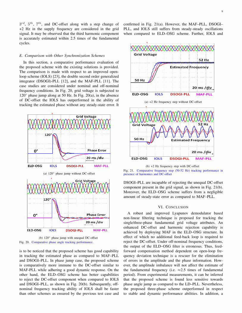
In this section, a comparative performance evaluation ofthe proposed scheme with the existing solutions is provided.The comparison is made with respect to an improved open-loop scheme (IOLS) [23], the double second order generalizedintegrator (DSOGI)-PLL [12], and the MAF-PLL [11]. Thecase studies are considered under nominal and off-nominalfrequency conditions. In Fig. 20, grid voltage is subjected to120◦ phase jump along at 50 Hz. In Fig. 20(a), in the absenceof DC-offset the IOLS has outperformed in the ability oftracking the estimated phase without any steady-state error. It
(a) 120◦ phase jump without DC-offset
(b) 120◦ phase jump with unequal DC-offsetFig. 20. Comparative phase angle tracking performance.
is to be noticed that the proposed scheme has good capabilityin tracking the estimated phase as compared to MAF–PLLand DSOGI–PLL. In phase jump case, the proposed schemeis comparatively more immune to the DC-offset similar toMAF-PLL while adhering a good dynamic response. On theother hand, the ELD–OSG scheme has better capabilitiesto reject the DC-offset component when compared to IOLSand DSOGI–PLL, as shown in Fig. 20(b). Subsequently, off-nominal frequency tracking ability of IOLS shall be fasterthan other schemes as ensured by the previous test case and
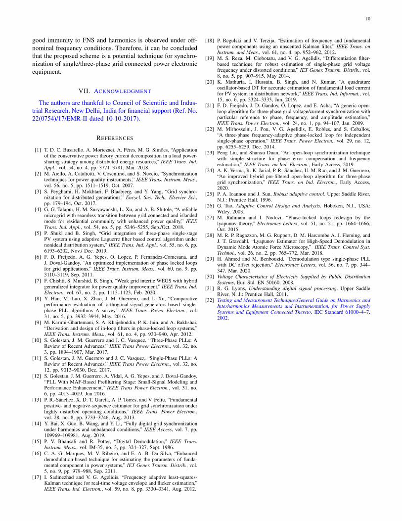
confirmed in Fig. 21(a). However, the MAF–PLL, DSOGI–PLL, and IOLS still suffers from steady-steady oscillationswhen compared to ELD–OSG scheme. Further, IOLS and
(a) +2 Hz frequency step without DC-offset
(b) +2 Hz frequency step with DC-offsetFig. 21. Comparative frequency step (50-52 Hz) tracking performance inpresence of harmonics and DC-offset
DSOGI–PLL are incapable of rejecting the unequal DC-offsetcomponent present in the grid signal, as shown in Fig. 21(b).Moreover, the ELD–OSG scheme suffers from a negligibleamount of steady-state error as compared to MAF–PLL.
VI. CONCLUSION
A robust and improved Lyapunov demodulator basednon-linear filtering technique is proposed for tracking thesingle/three-phase fundamental grid voltage attributes. Anenhanced DC-offset and harmonic rejection capability isachieved by deploying MAF in the ELD–OSG structure. Ineffect of which no additional feed-back loop is required toreject the DC-offset. Under off-nominal frequency conditions,the output of the ELD–OSG filter is erroneous. Thus, feed-forward compensation method dependent on open-loop fre-quency deviation technique is a rescuer for the eliminationof errors in the amplitude and the phase information. How-ever, the amplitude imbalance will not affect the estimate ofthe fundamental frequency (i.e. ≈2.5 times of fundamentalperiod). From experimental measurements, it can be inferredthat the proposed scheme is found less sensitive towardsphase angle jump as compared to the LD–PLL. Nevertheless,the proposed three-phase scheme outperformed in respectto stable and dynamic performance abilities. In addition, a
10
good immunity to FNS and harmonics is observed under off-nominal frequency conditions. Therefore, it can be concludedthat the proposed scheme is a potential technique for synchro-nization of single/three-phase grid connected power electronicequipment.
VII. ACKNOWLEDGMENT
The authors are thankful to Council of Scientific and Indus-trial Research, New Delhi, India for financial support (Ref. No.22(0754)/17/EMR-II dated 10-10-2017).
REFERENCES
[1] T. D. C. Busarello, A. Mortezaei, A. Peres, M. G. Simoes, “Applicationof the conservative power theory current decomposition in a load power-sharing strategy among distributed energy resources,” IEEE Trans. Ind.Appl., vol. 54, no. 4, pp. 3771–3781, Mar. 2018.
[2] M. Aiello, A. Cataliotti, V. Cosentino, and S. Nuccio, “Synchronizationtechniques for power quality instruments,” IEEE Trans. Instrum. Meas.,vol. 56, no. 5, pp. 1511–1519, Oct. 2007.
[3] S. Peyghami, H. Mokhtari, F. Blaabjerg, and Y. Yang, “Grid synchro-nization for distributed generations,” Encycl. Sus. Tech., Elsevier Sci.,pp. 179–194, Oct. 2017.
[4] G. G. Talapur, H. M. Suryawanshi, L. Xu, and A. B. Shitole, “A reliablemicrogrid with seamless transition between grid connected and islandedmode for residential community with enhanced power quality,” IEEETrans. Ind. Appl., vol. 54, no. 5, pp. 5246–5255, Sep./Oct. 2018.
[5] P. Shukl and B. Singh, “Grid integration of three-phase single-stagePV system using adaptive Laguerre filter based control algorithm undernonideal distribution system,” IEEE Trans. Ind. Appl., vol. 55, no. 6, pp.6193–6202, Nov./ Dec. 2019.
[6] F. D. Freijedo, A. G. Yepes, O. Lopez, P. Fernandez-Comesana, andJ. Doval-Gandoy, “An optimized implementation of phase locked loopsfor grid applications,” IEEE Trans. Instrum. Meas., vol. 60, no. 9, pp.3110–3119, Sep. 2011.
[7] F. Chishti, S. Murshid, B. Singh, “Weak grid intertie WEGS with hybridgeneralized integrator for power quality improvement,” IEEE Trans. Ind.Electron., vol. 67, no. 2, pp. 1113–1123, Feb. 2020.
[8] Y. Han, M. Luo, X. Zhao, J. M. Guerrero, and L. Xu, “Comparativeperformance evaluation of orthogonal-signal-generators-based single-phase PLL algorithms–A survey,” IEEE Trans. Power Electron., vol.31, no. 5, pp. 3932–3944, May. 2016.
[9] M. Karimi-Ghartemani, S. A. Khajehoddin, P. K. Jain, and A. Bakhshai,“Derivation and design of in-loop filters in phase-locked loop systems,”IEEE Trans. Instrum. Meas., vol. 61, no. 4, pp. 930–940, Apr. 2012.
[10] S. Golestan, J. M. Guerrero and J. C. Vasquez, “Three-Phase PLLs: AReview of Recent Advances,” IEEE Trans Power Electron., vol. 32, no.3, pp. 1894–1907, Mar. 2017.
[11] S. Golestan, J. M. Guerrero and J. C. Vasquez, “Single-Phase PLLs: AReview of Recent Advances,” IEEE Trans Power Electron., vol. 32, no.12, pp. 9013–9030, Dec. 2017.
[12] S. Golestan, J. M. Guerrero, A. Vidal, A. G. Yepes, and J. Doval-Gandoy,“PLL With MAF-Based Prefiltering Stage: Small-Signal Modeling andPerformance Enhancement,” IEEE Trans Power Electron., vol. 31, no.6, pp. 4013–4019, Jun 2016.
[13] P. R.-Sanchez, X. D. T. Garcıa, A. P. Torres, and V. Feliu, “Fundamentalpositive- and negative-sequence estimator for grid synchronization underhighly disturbed operating conditions,” IEEE Trans. Power Electron.,vol. 28, no. 8, pp. 3733–3746, Aug. 2013.
[14] Y. Bai, X. Guo, B. Wang, and Y. Li, “Fully digital grid synchronizationunder harmonics and unbalanced conditions,” IEEE Access, vol. 7, pp.109969–109981, Aug. 2019.
[15] P. V. Bhansali and R. Potter, “Digital Demodulation,” IEEE Trans.Instrum. Meas., vol. IM-35, no. 3, pp. 324–327, Sept. 1986.
[16] C. A. G. Marques, M. V. Ribeiro, and E. A. B. Da Silva, “Enhanceddemodulation-based technique for estimating the parameters of funda-mental component in power systems,” IET Gener. Transm. Distrib., vol.5, no. 9, pp. 979–988, Sep. 2011.
[17] I. Sadinezhad and V. G. Agelidis, “Frequency adaptive least-squares-Kalman technique for real-time voltage envelope and flicker estimation,”IEEE Trans. Ind. Electron., vol. 59, no. 8, pp. 3330–3341, Aug. 2012.
[18] P. Regulski and V. Terzija, “Estimation of frequency and fundamentalpower components using an unscented Kalman filter,” IEEE Trans. onInstrum. and Meas., vol. 61, no. 4, pp. 952–962, 2012.
[19] M. S. Reza, M. Ciobotaru, and V. G. Agelidis, “Differentiation filter-based technique for robust estimation of single-phase grid voltagefrequency under distorted conditions,” IET Gener. Transm. Distrib., vol.8, no. 5, pp. 907–915, May 2014.
[20] K. Mathuria, I. Hussain, B. Singh, and N. Kumar, “A quadratureoscillator-based DT for accurate estimation of fundamental load currentfor PV system in distribution network,” IEEE Trans. Ind. Informat., vol.15, no. 6, pp. 3324–3333, Jun. 2019.
[21] F. D. Freijedo, J. D.-Gandoy, O. Lopez, and E. Acha, “A generic open-loop algorithm for three-phase grid voltage/current synchronization withparticular reference to phase, frequency, and amplitude estimation,”IEEE Trans. Power Electron., vol. 24, no. 1, pp. 94–107, Jan. 2009.
[22] M. Mirhosseini, J. Pou, V. G. Agelidis, E. Robles, and S. Ceballos,“A three-phase frequency-adaptive phase-locked loop for independentsingle-phase operation,” IEEE Trans. Power Electron., vol. 29, no. 12,pp. 6255–6259, Dec. 2014.
[23] Peng Liu, and Shanxu Duan, “An open-loop synchronization techniquewith simple structure for phase error compensation and frequencyestimation,” IEEE Trans. on Ind. Electron., Early Access, 2019.
[24] A. K. Verma, R. K. Jarial, P. R.-Sanchez, U. M. Rao, and J. M. Guerrero,“An improved hybrid pre-filtered open-loop algorithm for three-phasegrid synchronization,” IEEE Trans. on Ind. Electron., Early Access,2020.
[25] P. A. Ioannou and J. Sun, Robust adaptive control. Upper Saddle River,N.J.: Prentice Hall, 1996.
[26] G. Tao, Adaptive Control Design and Analysis. Hoboken, N.J., USA:Wiley, 2003.
[27] M. Rahmani and I. Nodozi, “Phase-locked loops redesign by thelyapunov theory,” Electronics Letters, vol. 51, no. 21, pp. 1664–1666,Oct. 2015.
[28] M. R. P. Ragazzon, M. G. Ruppert, D. M. Harcombe A. J. Fleming, andJ. T. Gravdahl, “Lyapunov Estimator for High-Speed Demodulation inDynamic Mode Atomic Force Microscopy,” IEEE Trans. Control Syst.Technol., vol. 26, no. 2, pp. 765–772, Mar. 2018.
[29] H. Ahmed and M. Benbouzid, “Demodulation type single-phase PLLwith DC offset rejection,” Electronics Letters, vol. 56, no. 7, pp. 344–347, Mar. 2020.
[30] Voltage Characteristics of Electricity Supplied by Public DistributionSystems, Eur. Std. EN 50160, 2008.
[31] R. G. Lyons, Understanding digital signal processing. Upper SaddleRiver, N. J.: Prentice Hall, 2011.
[32] Testing and Measurement TechniquesGeneral Guide on Harmonics andInterharmonics Measurements and Instrumentation, for Power SupplySystems and Equipment Connected Thereto, IEC Standard 61000–4–7,2002.