Embed Size (px)
Citation preview
Renewable Energy 23 (2001) 261–292www.elsevier.nl/locate/renene
A review of impulse turbines for wave energyconversion
T. Setoguchia,*, S. Santhakumarb, H. Maedac, M. Takaoa,K. Kanekoa
a Department of Mechanical Engineering, Saga University, Saga, Japanb Department of Aerospace Engineering, I.I.T., Madras, India
c Torishima Pump Manufacturing Company Limited, Saga, Japan
Received 25 May 1999; accepted 24 August 2000
Abstract
Oscillating Water Column based wave energy plants convert wave energy into low pressurepnuematic power in the form of bi-directional air flows. Air turbines which are capable ofrotating uni-directionally in bi-directional air flow, otherwise also known as self-rectifyingturbines, are used to extract mechanical shaft power which is further converted into electricalpower by a generator. This paper reviews the state of the art in self-rectifying impulse airturbines. New results on optimum parameters for the fixed-guide-vane impulse turbine are alsopresented. Starting characteristics and conversion efficiencies of two types of impulse turbinesare compared with the well known Wells turbine. 2001 Elsevier Science Ltd. All rightsreserved.
Keywords:Fluid machinery; Impulse turbine; Wells turbine; Guide vane; Ocean energy; Wave energyconversion
1. Introduction
One of the methods for wave energy conversion utilises an Oscillating WaterColumn (OWC) which in turn converts wave energy into low pressure pneumaticenergy in the form of bi-directional air flow. An air turbine which rotates in a singledirection and extracts mechanical shaft power from such bi-directional air flow is
* Corresponding author.E-mail address:[email protected] (T. Setoguchi).
0960-1481/01/$ - see front matter 2001 Elsevier Science Ltd. All rights reserved.PII: S0960 -1481(00 )00175-0
262 T. Setoguchi et al. / Renewable Energy 23 (2001) 261–292
Nomenclature
a semi-major axis of ellipseAc air chamber cross-sectional areaAt turbine flow passage areab blade heightCA input coefficient {Eq. (1)}CT torque coefficnet {Eq. (2)}d slot width {see Fig. 3(b)}e semi-minor axis of ellipsef frequency of wave motionf̄ mean frequency of wave motion= 1/T̄f* nondimensional frequency= f/f̄h wave height in air chamberh* nondimensional wave height in air chamber= h/H1/3
H incident wave heightH1/3 significant wave heightH* nondimensional incident wave= H/H1/3
I moment of inertia of rotorlr chord length of rotor bladelg chord length of guide vaneN number of wavesm At/Ac
K nondimensional period= rRm/H1/3
Q flow raterR mean radiusrr radius of circular arc of pressure side of elliptic profile {see Fig.
4(b) and Fig. 21}R1 radius of circular arc of pressure side of simple profile {see Fig.
4(a)}R2 radius of circular arc of suction side of simple profile {see Fig.
4(a)}Sg guide vane pitchSr rotor blade pitchS* nondimensional spectrum of wave motiont timet* nondimensional time in sinusoidal flow= t/Tt̄∗ nondimensional time in irregular flow= t/T̄ta width of flow path (see Fig. 4)T period of wave motionTo turbine output torqueTL loading torqueT̄ mean period in irregular flow 1/f̄UR circumferential velocity atrR
νa mean axial flow velocity
263T. Setoguchi et al. / Renewable Energy 23 (2001) 261–292
νa* nondimensional axial flow velocity= νa/V
V reference velocity= H1/3/(mT̄)Va peak value ofνa in sinusoidal flowW̄i incident wave power {Eq. (10)}W̄0 OWC output power {Eq. (11)}XI nondimensional moment of inertia=I/(prar5
R)XL nondimensional loading torque=TL/(praV2
ar3R), TL/(praV2r3
R)z number of rotor bladesα incident angle of guide vane (see Fig. 2)γ rotor blade inlet angle (Fig. 4)λ rotor blade sweep angle (Fig. 10)δ camber angle of guide vaneDp total pressure drop between settling chamber and atmosphereη turbine efficiency under steady flow condition {Eq. (3)}ηm maximum value ofηh̄ mean turbine efficiency under sinusoidal flow condition {Eq. (5)}h̄m maximum value ofh̄h̃ conversion efficiency under irregular flow condition {Eq. (18)}h̃c efficiency of air chamber {Eq. (12)}h̃t mean turbine efficiency under irregular flow condition {Eq. (17)}θ setting angle of fixed guide vaneθp pitch angle of guide vaneθ1 setting angle of upstream guide vaneθ2 setting angle of downstream guide vaneν hub-to-tip ratioρa density of airρs density of seawaterσ solidity of rotor atrR
φ flow coefficient {Eq. (4)}F flow coefficient {Eq. (6)}ω angular velocity of turbine rotorω* nondimensional angular velocity in sinusoidal flow= ωTw̄∗ nondimensional angular velocity in irregular flowwT̄
required to drive a generator to produce electricity. Such a turbine is also called aself-rectifying turbine. Different types of impulse turbines have been proposed overthe years [1] but generally their performance has not been investigated except maybe in the case of McCormick turbine whose efficiency is found to be rather low.
The Wells turbine was the first choice for all the OWC based wave energy plantswhich were built in Norway, Japan, Scotland, India and China.
There are many reports which describe the performance of the Wells turbine bothat starting and running conditions [2–4]. According to these results, the Wells turbine
264 T. Setoguchi et al. / Renewable Energy 23 (2001) 261–292
has inherent disadvantages: narrow range of flow rates at which it operates at usefulefficiencies, poor starting characteristics, high speed operation and consequent noiseand high axial thrust.
Setoguchi et al. [5–12] developed an impulse turbine with self-pitch controlledguide vanes and subsequently with linked guide vanes to overcome the drawbacksof the Wells turbine.
This design delivers useful efficiencies over a wide range of flow rates, has verygood starting characteristics and low operating speeds. These characteristics havebeen borne out by field trials conducted by the National Institute of Ocean Tech-nology, India, on a 1-meter-diameter turbine at Vizhinjam on the west coast of India.
Notwithstanding the superior characteristics of the impulse turbine with self-pitch-controlled guide vanes, certain disadvantages are imposed by such variable-geometrydesign. The guide vanes pitch at the wave frequency calling for a robust mechanicaldesign to withstand a large number of oscillation cycles per day. Presence of manymoving parts lead to maintenance and operating life problems and more cost. If fixedguide vanes are provided instead, it was felt that these problems will be mitigatedeven though the performance may be poorer. With this in view, model tests wereconducted to determine the characteristics of fixed-guide-vane impulse turbine. Theresults were encouraging and more tests were conducted to optimise various para-meters of the turbine. Site trial also shows the validity of this concept.
The objective of this paper is to show the present state of the art of the impulseturbine with self-pitch-controlled guide vane and of the fixed-guide-vane impulseturbine. In addition, new results on the effect of hub-to-tip diameter ratio and rotor-stator gap on the performance of fixed-guide-vane impulse turbine are also presented.
2. Description of the oscillatory flow test rig
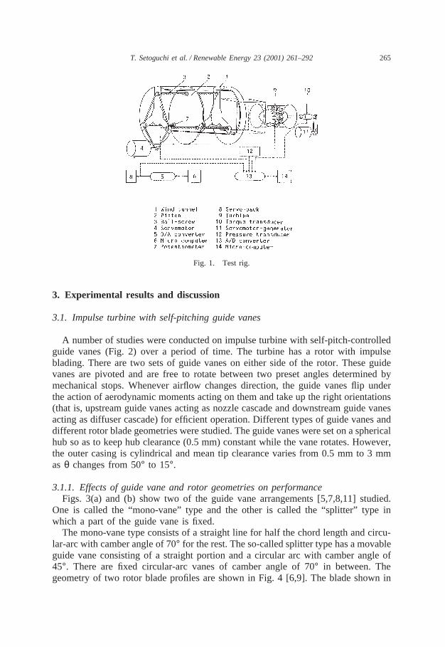
The test rig used for testing turbines consists of a large piston-cylinder, a settlingchamber and 300 mm diameter test section with entry/exit at its two ends which arebell-mouthed (Fig. 1). The test-turbine is placed at the centre of the test section. Itis coupled through a torque transducer to an electrical generator/motor which iselectronically controlled to maintain the rpm constant at any set value. The pistonis translated by means of three ball-screws which are driven by a d.c. servo-motorby chain and sprockets. A computer controls this motor to produce sinusoidal flow,any random/irregular flow or steady flow (for a short period) through the turbine.Average flow rate is measured by pitot-tube survey. Settling chamber pressure ismeasured by a pressure transducer. Turbine performance is evaluated from turbinerpm, turbine output torque, flow rate and total pressure drop between settlingchamber and atmosphere. Tests were performed for total pressure drops in the rangeof 200 to 800 N/m2, turbine angular velocity up to 370 rad/s and flow rates upto0.63 m3/s. The measurement uncertainty in turbine efficiency is about±2%. Formeasuring guide vane angleθp, a potentiometer was used.
265T. Setoguchi et al. / Renewable Energy 23 (2001) 261–292
Fig. 1. Test rig.
3. Experimental results and discussion
3.1. Impulse turbine with self-pitching guide vanes
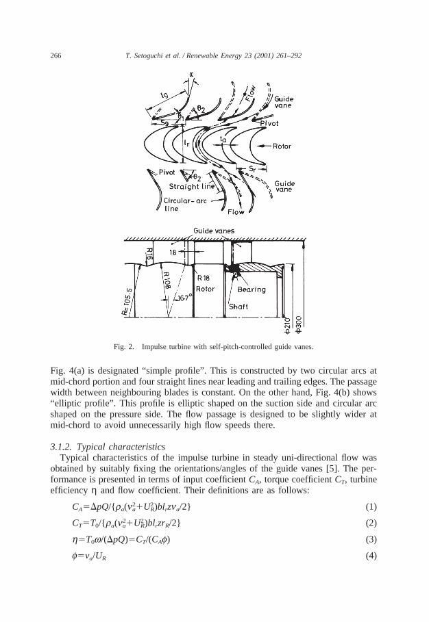
A number of studies were conducted on impulse turbine with self-pitch-controlledguide vanes (Fig. 2) over a period of time. The turbine has a rotor with impulseblading. There are two sets of guide vanes on either side of the rotor. These guidevanes are pivoted and are free to rotate between two preset angles determined bymechanical stops. Whenever airflow changes direction, the guide vanes flip underthe action of aerodynamic moments acting on them and take up the right orientations(that is, upstream guide vanes acting as nozzle cascade and downstream guide vanesacting as diffuser cascade) for efficient operation. Different types of guide vanes anddifferent rotor blade geometries were studied. The guide vanes were set on a sphericalhub so as to keep hub clearance (0.5 mm) constant while the vane rotates. However,the outer casing is cylindrical and mean tip clearance varies from 0.5 mm to 3 mmas θ changes from 50° to 15°.
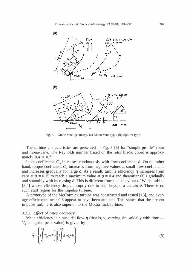
3.1.1. Effects of guide vane and rotor geometries on performanceFigs. 3(a) and (b) show two of the guide vane arrangements [5,7,8,11] studied.
One is called the “mono-vane” type and the other is called the “splitter” type inwhich a part of the guide vane is fixed.
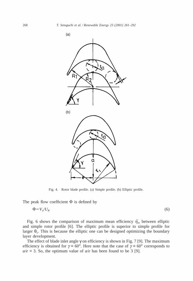
The mono-vane type consists of a straight line for half the chord length and circu-lar-arc with camber angle of 70° for the rest. The so-called splitter type has a movableguide vane consisting of a straight portion and a circular arc with camber angle of45°. There are fixed circular-arc vanes of camber angle of 70° in between. Thegeometry of two rotor blade profiles are shown in Fig. 4 [6,9]. The blade shown in
266 T. Setoguchi et al. / Renewable Energy 23 (2001) 261–292
Fig. 2. Impulse turbine with self-pitch-controlled guide vanes.
Fig. 4(a) is designated “simple profile”. This is constructed by two circular arcs atmid-chord portion and four straight lines near leading and trailing edges. The passagewidth between neighbouring blades is constant. On the other hand, Fig. 4(b) shows“elliptic profile”. This profile is elliptic shaped on the suction side and circular arcshaped on the pressure side. The flow passage is designed to be slightly wider atmid-chord to avoid unnecessarily high flow speeds there.
3.1.2. Typical characteristicsTypical characteristics of the impulse turbine in steady uni-directional flow was
obtained by suitably fixing the orientations/angles of the guide vanes [5]. The per-formance is presented in terms of input coefficientCA, torque coefficientCT, turbineefficiency η and flow coefficient. Their definitions are as follows:
CA5DpQ/{ra(n2a1U2
R)blrzna/2} (1)
CT5T0/{ra(n2a1U2
R)blrzrR/2} (2)
h5T0w/(DpQ)5CT/(CAf) (3)
f5va/UR (4)
267T. Setoguchi et al. / Renewable Energy 23 (2001) 261–292
Fig. 3. Guide vane geometry. (a) Mono vane type. (b) Splitter type.
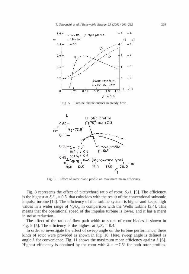
The turbine characteristics are presented in Fig. 5 [5] for “simple profile” rotorand mono-vane. The Reynolds number based on the rotor blade, chord is approxi-mately 0.4× 10⁵.
Input coefficient,CA increases continuously with flow coefficientf. On the otherhand, torque coefficientCT increases from negative values at small flow coefficientsand increases gradually for largef. As a result, turbine efficiencyη increases fromzero atf = 0.15 to reach a maximum value atf = 0.4 and thereafter falls graduallyand smoothly with increasingf. This is different from the behaviour of Wells turbine[3,4] whose efficiency drops abruptly due to stall beyond a certainf. There is nosuch stall region for the impulse turbine.
A prototype of the McCormick turbine was constructed and tested [13], and aver-age efficiencies near 0.3 appear to have been attained. This shows that the presentimpulse turbine is also superior to the McCormick turbine.
3.1.3. Effect of rotor geometryMean efficiency in sinusoidal flowh̄ (that is,va varying sinusoidally with time —
Va being the peak value) is given by
h̄55fE1/f
0
T0wdtJ|HfE1/f
0
DpQdt6 (5)
268 T. Setoguchi et al. / Renewable Energy 23 (2001) 261–292
Fig. 4. Rotor blade profile. (a) Simple profile. (b) Elliptic profile.
The peak flow coefficientF is defined by
F5Va/UR (6)
Fig. 6 shows the comparison of maximum mean efficiencyh̄m between ellipticand simple rotor profile [6]. The elliptic profile is superior to simple profile forlargerθ1. This is because the elliptic one can be designed optimizing the boundarylayer development.
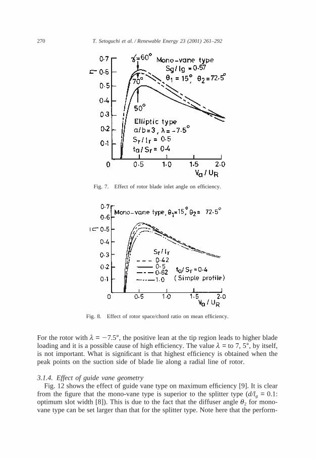
The effect of blade inlet angleγ on efficiency is shown in Fig. 7 [9]. The maximumefficiency is obtained forg = 60°. Here note that the case ofg = 60° corresponds toa/e = 3. So, the optimum value ofa/e has been found to be 3 [9].
269T. Setoguchi et al. / Renewable Energy 23 (2001) 261–292
Fig. 5. Turbine characteristics in steady flow.
Fig. 6. Effect of rotor blade profile on maximum mean efficiency.
Fig. 8 represents the effect of pitch/chord ratio of rotor,Sr/1r [5]. The efficiencyis the highest atSr/1r = 0.5, that coincides with the result of the conventional subsonicimpulse turbine [14]. The efficiency of this turbine system is higher and keeps highvalues in a wider range ofVa/UR in comparison with the Wells turbine [3,4]. Thismeans that the operational speed of the impulse turbine is lower, and it has a meritin noise reduction.
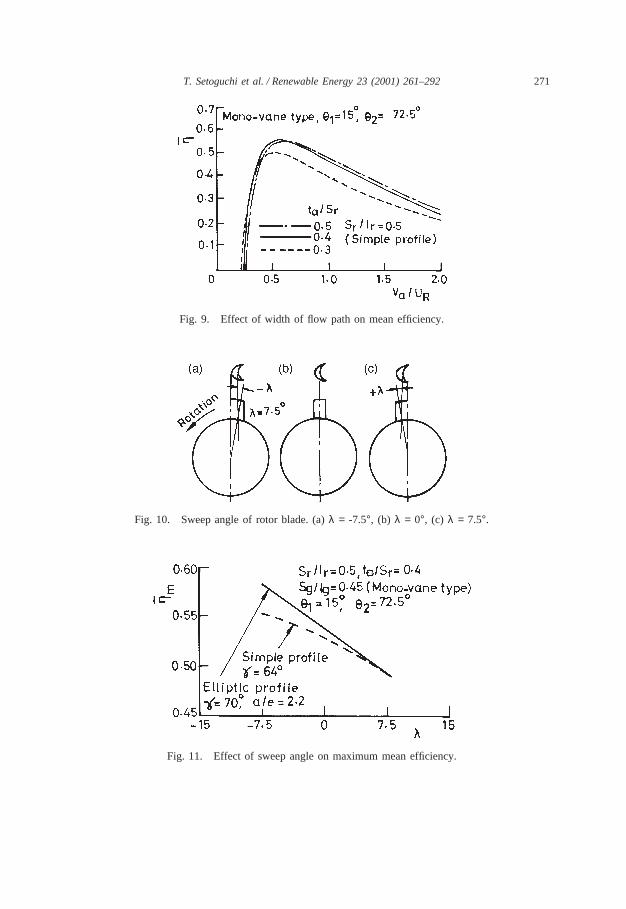
The effect of the ratio of flow path width to space of rotor blades is shown inFig. 9 [5]. The efficiency is the highest atta/Sr = 0.4.
In order to investigate the effect of sweep angle on the turbine performance, threekinds of rotor were provided as shown in Fig. 10. Here, sweep angle is defined asanglel for convenience. Fig. 11 shows the maximum mean efficiency againstl [6].Highest efficiency is obtained by the rotor withl = 27.5° for both rotor profiles.
270 T. Setoguchi et al. / Renewable Energy 23 (2001) 261–292
Fig. 7. Effect of rotor blade inlet angle on efficiency.
Fig. 8. Effect of rotor space/chord ratio on mean efficiency.
For the rotor withl = 27.5°, the positive lean at the tip region leads to higher bladeloading and it is a possible cause of high efficiency. The valuel = to 7, 5°, by itself,is not important. What is significant is that highest efficiency is obtained when thepeak points on the suction side of blade lie along a radial line of rotor.
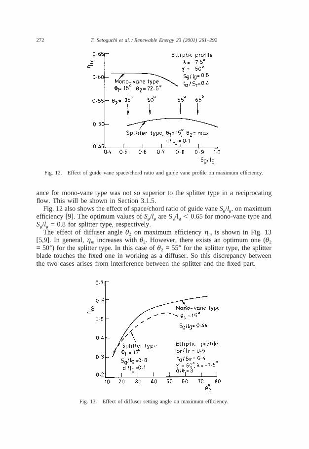
3.1.4. Effect of guide vane geometryFig. 12 shows the effect of guide vane type on maximum efficiency [9]. It is clear
from the figure that the mono-vane type is superior to the splitter type (d/lg = 0.1:optimum slot width [8]). This is due to the fact that the diffuser angleq2 for mono-vane type can be set larger than that for the splitter type. Note here that the perform-
271T. Setoguchi et al. / Renewable Energy 23 (2001) 261–292
Fig. 9. Effect of width of flow path on mean efficiency.
Fig. 10. Sweep angle of rotor blade. (a)λ = -7.5°, (b) λ = 0°, (c) λ = 7.5°.
Fig. 11. Effect of sweep angle on maximum mean efficiency.
272 T. Setoguchi et al. / Renewable Energy 23 (2001) 261–292
Fig. 12. Effect of guide vane space/chord ratio and guide vane profile on maximum efficiency.
ance for mono-vane type was not so superior to the splitter type in a reciprocatingflow. This will be shown in Section 3.1.5.
Fig. 12 also shows the effect of space/chord ratio of guide vaneSg/lg. on maximumefficiency [9]. The optimum values ofSg/lg are Sg/lg , 0.65 for mono-vane type andSg/lg = 0.8 for splitter type, respectively.
The effect of diffuser angleq2 on maximum efficiencyhm is shown in Fig. 13[5,9]. In general,hm increases withq2. However, there exists an optimum one (q2
= 50°) for the splitter type. In this case ofq2 = 55° for the splitter type, the splitterblade touches the fixed one in working as a diffuser. So this discrepancy betweenthe two cases arises from interference between the splitter and the fixed part.
Fig. 13. Effect of diffuser setting angle on maximum efficiency.
273T. Setoguchi et al. / Renewable Energy 23 (2001) 261–292
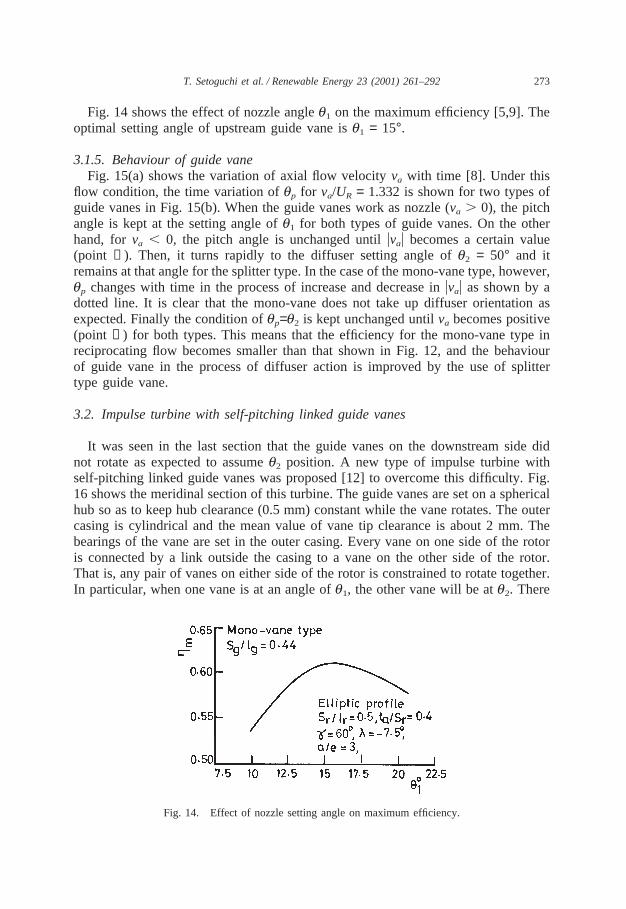
Fig. 14 shows the effect of nozzle angleq1 on the maximum efficiency [5,9]. Theoptimal setting angle of upstream guide vane isq1 = 15°.
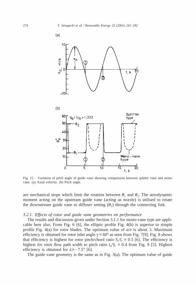
3.1.5. Behaviour of guide vaneFig. 15(a) shows the variation of axial flow velocityva with time [8]. Under this
flow condition, the time variation ofqp for va/UR = 1.332 is shown for two types ofguide vanes in Fig. 15(b). When the guide vanes work as nozzle (va . 0), the pitchangle is kept at the setting angle ofq1 for both types of guide vanes. On the otherhand, forva , 0, the pitch angle is unchanged untiluvau becomes a certain value(point ➀). Then, it turns rapidly to the diffuser setting angle ofq2 = 50° and itremains at that angle for the splitter type. In the case of the mono-vane type, however,qp changes with time in the process of increase and decrease inuvau as shown by adotted line. It is clear that the mono-vane does not take up diffuser orientation asexpected. Finally the condition ofqp=q2 is kept unchanged untilva becomes positive(point ➁) for both types. This means that the efficiency for the mono-vane type inreciprocating flow becomes smaller than that shown in Fig. 12, and the behaviourof guide vane in the process of diffuser action is improved by the use of splittertype guide vane.
3.2. Impulse turbine with self-pitching linked guide vanes
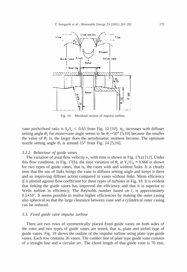
It was seen in the last section that the guide vanes on the downstream side didnot rotate as expected to assumeq2 position. A new type of impulse turbine withself-pitching linked guide vanes was proposed [12] to overcome this difficulty. Fig.16 shows the meridinal section of this turbine. The guide vanes are set on a sphericalhub so as to keep hub clearance (0.5 mm) constant while the vane rotates. The outercasing is cylindrical and the mean value of vane tip clearance is about 2 mm. Thebearings of the vane are set in the outer casing. Every vane on one side of the rotoris connected by a link outside the casing to a vane on the other side of the rotor.That is, any pair of vanes on either side of the rotor is constrained to rotate together.In particular, when one vane is at an angle ofq1, the other vane will be atq2. There
Fig. 14. Effect of nozzle setting angle on maximum efficiency.
274 T. Setoguchi et al. / Renewable Energy 23 (2001) 261–292
Fig. 15. Variation of pitch angle of guide vane showing comparision between splitter vane and monovane. (a) Axial velocity. (b) Pitch angle.
are mechanical stops which limit the rotation betweenq1 andq2. The aerodynamicmoment acting on the upstream guide vane (acting as nozzle) is utilised to rotatethe downstream guide vane to diffuser setting (q2) through the connecting link.
3.2.1. Effects of rotor and guide vane geometries on performanceThe results and discussion given under Section 3.1.1 for mono-vane type are appli-
cable here also. From Fig. 6 [6], the elliptic profile Fig. 4(b) is superior to simpleprofile Fig. 4(a) for rotor blades. The optimum value ofa/e is about 3. Maximumefficiency is obtained for rotor inlet angleg = 600 as seen from Fig. 7[9]. Fig. 8 showsthat efficiency is highest for rotor pitch/chord ratioSr/lr = 0.5 [6]. The efficiency ishighest for rotor flow path width to pitch ratiota/Sr = 0.4 from Fig. 9 [5]. Highestefficiency is obtained forl=27.5° [6].
The guide vane geometry is the same as in Fig. 3(a). The optimum value of guide
275T. Setoguchi et al. / Renewable Energy 23 (2001) 261–292
Fig. 16. Meridinal section of impulse turbine.
vane pitch/chord ratio isSg/lg , 0.65 from Fig. 12 [10].hm increases with diffusersetting angleq2 for mono-vane angle seems to beq2<50° [5,10] because the smallerthe value ofq2 is, the larger does the aerodynamic moment become. The optimumnozzle setting angleq1 is around 15° from Fig. 14 [5,10].
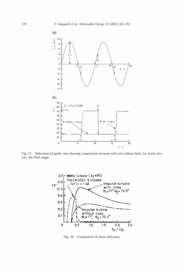
3.2.2. Behaviour of guide vanesThe variation of axial flow velocityva with time is shown in Fig. 17(a) [12]. Under
this flow condition, in Fig. 17(b), the time variation ofqp at Va/UR = 0.666 is shownfor two types of guide vanes, that is, the cases with and without links. It is clearlyseen that the use of links brings the vane to diffuser setting angle and keeps it thereand so improving diffuser action compared to vanes without links. Mean efficiencyh̄ is plotted against flow coefficient for three types of turbines in Fig. 18. It is evidentthat linking the guide vanes has improved the efficiency and that it is superior toWells turbine in efficiency. The Reynolds number based onlr is approximately0.5×105. It seems possible to realise higher efficiencies by making the outer casingalso spherical so that the large clearance between vane and a cylindrical outer casingcan be reduced.
3.3. Fixed guide vane impulse turbine
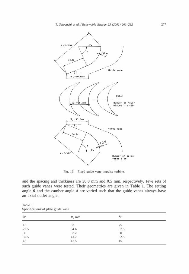
There are two rows of symmetrically placed fixed guide vanes on both sides ofthe rotor and two types of guide vanes are tested, that is, plate and airfoil type ofguide vanes. Fig. 19 shows the outline of the impulse turbine using plate type guidevanes. Each row contains 26 vanes. The camber line of plate type guide vane consistsof a straight line and a circular arc. The chord length of that guide vane is 70 mm,
276 T. Setoguchi et al. / Renewable Energy 23 (2001) 261–292
Fig. 17. Behaviour of guide vane showing comparision between with and without links. (a) Axial velo-city. (b) Pitch angle.
Fig. 18. Comparison of mean efficiency.
277T. Setoguchi et al. / Renewable Energy 23 (2001) 261–292
Fig. 19. Fixed guide vane impulse turbine.
and the spacing and thickness are 30.8 mm and 0.5 mm, respectively. Five sets ofsuch guide vanes were tested. Their geometries are given in Table 1. The settingangleq and the camber angled are varied such that the guide vanes always havean axial outlet angle.
Table 1Specifications of plate guide vane
θ° Ra mm δ°
15 32 7522.5 34.6 67.530 37.2 6037.5 41.7 52.545 47.5 45
278 T. Setoguchi et al. / Renewable Energy 23 (2001) 261–292
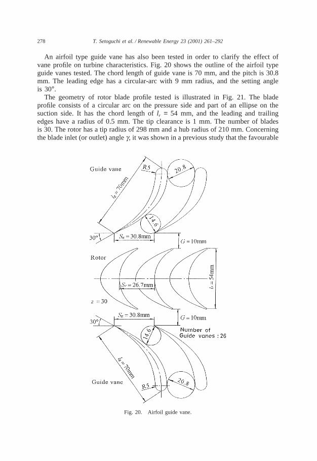
An airfoil type guide vane has also been tested in order to clarify the effect ofvane profile on turbine characteristics. Fig. 20 shows the outline of the airfoil typeguide vanes tested. The chord length of guide vane is 70 mm, and the pitch is 30.8mm. The leading edge has a circular-arc with 9 mm radius, and the setting angleis 30°.
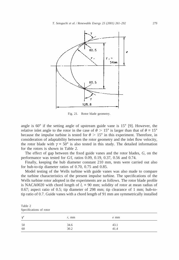
The geometry of rotor blade profile tested is illustrated in Fig. 21. The bladeprofile consists of a circular arc on the pressure side and part of an ellipse on thesuction side. It has the chord length oflr = 54 mm, and the leading and trailingedges have a radius of 0.5 mm. The tip clearance is 1 mm. The number of bladesis 30. The rotor has a tip radius of 298 mm and a hub radius of 210 mm. Concerningthe blade inlet (or outlet) angleg, it was shown in a previous study that the favourable
Fig. 20. Airfoil guide vane.
279T. Setoguchi et al. / Renewable Energy 23 (2001) 261–292
Fig. 21. Rotor blade geometry.
angle is 60° if the setting angle of upstream guide vane is 15° [9]. However, therelative inlet angle to the rotor in the case ofq . 15° is larger than that ofq = 15°because the impulse turbine is tested forq . 15° in this experiment. Therefore, inconsideration of adaptability between the rotor geometry and the inlet flow velocity,the rotor blade withg = 50° is also tested in this study. The detailed informationfor the rotors is shown in Table 2.
The effect of gap between the fixed guide vanes and the rotor blades,G, on theperformance was tested forG/lr ratios 0.09, 0.19, 0.37, 0.56 and 0.74.
Finally, keeping the hub diameter constant 210 mm, tests were carried out alsofor hub-to-tip diameter ratios of 0.70, 0.75 and 0.85.
Model testing of the Wells turbine with guide vanes was also made to comparethe turbine characteristics of the present impulse turbine. The specifications of theWells turbine rotor adopted in the experiments are as follows. The rotor blade profileis NACA0020 with chord length oflr = 90 mm; solidity of rotor at mean radius of0.67; aspect ratio of 0.5; tip diameter of 298 mm; tip clearance of 1 mm; hub-to-tip ratio of 0.7. Guide vanes with a chord length of 91 mm are symmetrically installed
Table 2Specifications of rotor
γ° rr mm e mm
50 34.6 43.160 30.2 41.4
280 T. Setoguchi et al. / Renewable Energy 23 (2001) 261–292
at a distance of 39 mm downstream and upstream of the rotor. Detailed informationabout the guide vane is as follows: circular are profile with constant thickness ratioof 0.011; solidity at mean radius of 1.25; camber angle of 600; aspect ratio of 0.5;gap to chord ratio of 0.43; stagger angle of 16.30; and leading and trailing edgesrounded to a semicircle with a radius of 0.5 mm. Note here that this turbine isconsidered the most promising one in the previous studies [15–17].
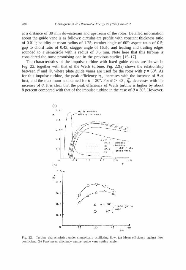
The characteristics of the impulse turbine with fixed guide vanes are shown inFig. 22, together with that of the Wells turbine. Fig. 22(a) shows the relationshipbetweenh̄ andF, where plate guide vanes are used for the rotor withg = 60°. Asfor this impulse turbine, the peak efficiencyh̄m increases with the increase ofq atfirst, and the maximum is obtained forq = 30°. For q . 30°, h̄m decreases with theincrease ofq. It is clear that the peak efficiency of Wells turbine is higher by about8 percent compared with that of the impulse turbine in the case ofq = 30°. However,
Fig. 22. Turbine characteristics under sinusoidally oscillating flow. (a) Mean efficiency against flowcoefficient. (b) Peak mean efficiency against guide vane setting angle.
281T. Setoguchi et al. / Renewable Energy 23 (2001) 261–292
the efficiency of the impulse turbine is higher over a wider range of peak flowcoefficientF in comparison with the Wells turbine.
Fig. 22(b) shows the effect of setting angleq on the peak mean efficiencyh̄m fortwo inlet angles of rotor blade.h̄m for g = 60° is higher than that for 50° for the allsetting angles. Therefore, it is clear that the favourable inlet (or outlet) angle of rotorblade is 60°, which is similar to the previous result [9].
Now, let us consider the causes of the above mentioned characteristics on thebasis of experimental results obtained under steady flow conditions.
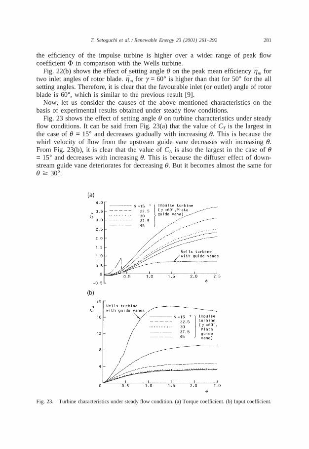
Fig. 23 shows the effect of setting angleq on turbine characteristics under steadyflow conditions. It can be said from Fig. 23(a) that the value ofCT is the largest inthe case ofq = 15° and decreases gradually with increasingq. This is because thewhirl velocity of flow from the upstream guide vane decreases with increasingq.From Fig. 23(b), it is clear that the value ofCA is also the largest in the case ofq= 15° and decreases with increasingq. This is because the diffuser effect of down-stream guide vane deteriorates for decreasingq. But it becomes almost the same forq $ 30°.
Fig. 23. Turbine characteristics under steady flow condition. (a) Torque coefficient. (b) Input coefficient.
282 T. Setoguchi et al. / Renewable Energy 23 (2001) 261–292
The difference in the running characteristics between the impulse turbine and theWells turbine can be explained as follows. From Fig. 23(a), at small flow coefficient,high output torqueT0 is obtained in the case of Wells turbine, and then the efficiencywould become higher. However, forf . 0.36 (this corresponds to a stall point),T0
for the case of Wells turbine is very small, and the value ofCA increases with theincrease off as shown in Fig. 6(b). Therefore, the turbine efficiency of Wells turbinewould become quite low forf . 0.36. This means that the performance of Wellsturbine might deteriorate in irregular oscillating flow since it will experience highflow coefficients often.
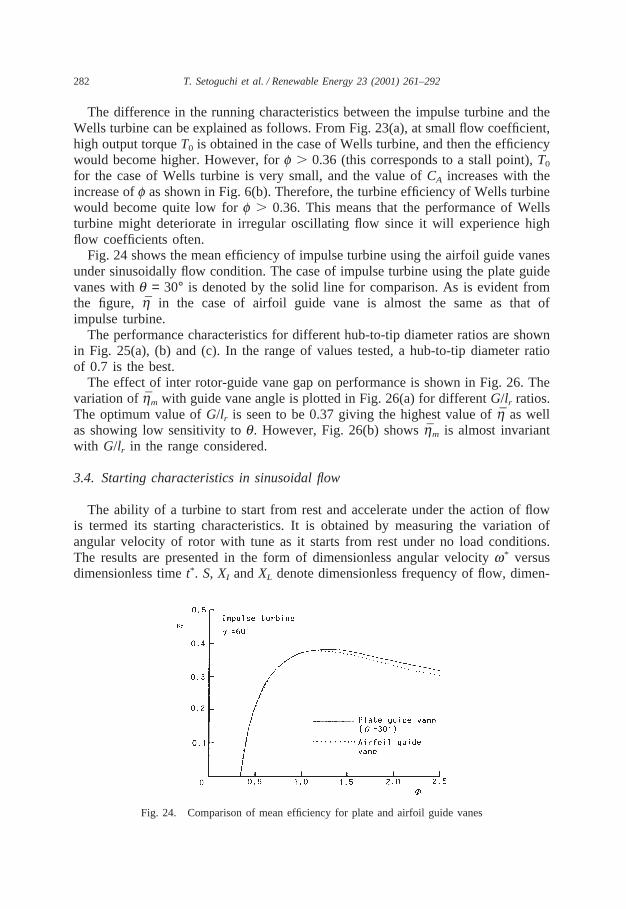
Fig. 24 shows the mean efficiency of impulse turbine using the airfoil guide vanesunder sinusoidally flow condition. The case of impulse turbine using the plate guidevanes withq = 30° is denoted by the solid line for comparison. As is evident fromthe figure, h̄ in the case of airfoil guide vane is almost the same as that ofimpulse turbine.
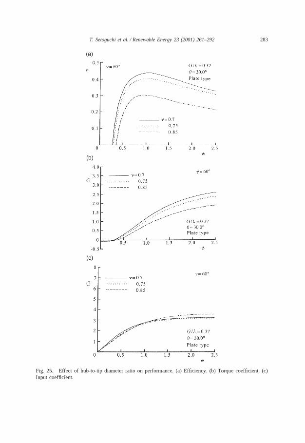
The performance characteristics for different hub-to-tip diameter ratios are shownin Fig. 25(a), (b) and (c). In the range of values tested, a hub-to-tip diameter ratioof 0.7 is the best.
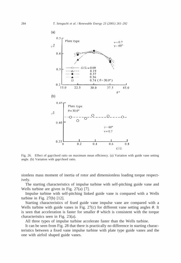
The effect of inter rotor-guide vane gap on performance is shown in Fig. 26. Thevariation ofh̄m with guide vane angle is plotted in Fig. 26(a) for differentG/lr ratios.The optimum value ofG/lr is seen to be 0.37 giving the highest value ofh̄ as wellas showing low sensitivity toq. However, Fig. 26(b) showsh̄m is almost invariantwith G/lr in the range considered.
3.4. Starting characteristics in sinusoidal flow
The ability of a turbine to start from rest and accelerate under the action of flowis termed its starting characteristics. It is obtained by measuring the variation ofangular velocity of rotor with tune as it starts from rest under no load conditions.The results are presented in the form of dimensionless angular velocityw* versusdimensionless timet*. S, XI andXL denote dimensionless frequency of flow, dimen-
Fig. 24. Comparison of mean efficiency for plate and airfoil guide vanes
283T. Setoguchi et al. / Renewable Energy 23 (2001) 261–292
Fig. 25. Effect of hub-to-tip diameter ratio on performance. (a) Efficiency. (b) Torque coefficient. (c)Input coefficient.
284 T. Setoguchi et al. / Renewable Energy 23 (2001) 261–292
Fig. 26. Effect of gap/chord ratio on maximum mean efficiency. (a) Variation with guide vane settingangle. (b) Variation with gap/chord ratio.
sionless mass moment of inertia of rotor and dimensionless loading torque respect-ively.
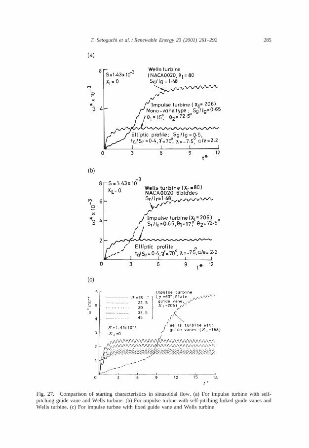
The starting characteristics of impulse turbine with self-pitching guide vane andWells turbine are given in Fig. 27(a) [7].
Impulse turbine with self-pitching linked guide vane is compared with a Wellsturbine in Fig. 27(b) [12].
Starting characteristics of fixed guide vane impulse vane are compared with aWells turbine with guide vanes in Fig. 27(c) for different vane setting anglesq. Itis seen that acceleration is faster for smallerq which is consistent with the torquecharacteristics seen in Fig. 23(a).
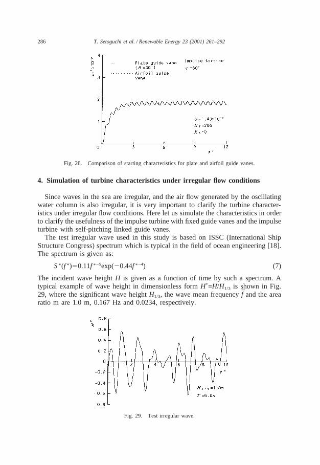
All three types of impulse turbine accelerate faster than the Wells turbine.It can be seen from Fig. 28 that there is practically no difference in starting charac-
teristics between a fixed vane impulse turbine with plate type guide vanes and theone with airfoil shaped guide vanes.
285T. Setoguchi et al. / Renewable Energy 23 (2001) 261–292
Fig. 27. Comparison of starting characteristics in sinusoidal flow. (a) For impulse turbine with self-pitching guide vane and Wells turbine. (b) For impulse turbne with self-pitching linked guide vanes andWells turbine. (c) For impulse turbne with fixed guide vane and Wells turbine
286 T. Setoguchi et al. / Renewable Energy 23 (2001) 261–292
Fig. 28. Comparison of starting characteristics for plate and airfoil guide vanes.
4. Simulation of turbine characteristics under irregular flow conditions
Since waves in the sea are irregular, and the air flow generated by the oscillatingwater column is also irregular, it is very important to clarify the turbine character-istics under irregular flow conditions. Here let us simulate the characteristics in orderto clarify the usefulness of the impulse turbine with fixed guide vanes and the impulseturbine with self-pitching linked guide vanes.
The test irregular wave used in this study is based on ISSC (International ShipStructure Congress) spectrum which is typical in the field of ocean engineering [18].The spectrum is given as:
S∗(f∗)50.11f∗−5exp(20.44f∗−4) (7)
The incident wave heightH is given as a function of time by such a spectrum. Atypical example of wave height in dimensionless formH*=H/H1/3 is shown in Fig.29, where the significant wave heightH1/3, the wave mean frequencyf̄ and the arearatio m are 1.0 m, 0.167 Hz and 0.0234, respectively.
Fig. 29. Test irregular wave.
287T. Setoguchi et al. / Renewable Energy 23 (2001) 261–292
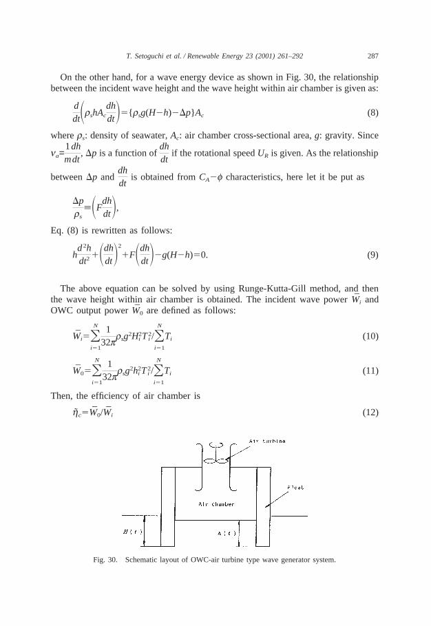
On the other hand, for a wave energy device as shown in Fig. 30, the relationshipbetween the incident wave height and the wave height within air chamber is given as:
ddtSrshAc
dhdtD5{rsg(H2h)2Dp} Ac (8)
wherers: density of seawater,Ac: air chamber cross-sectional area,g: gravity. Since
na=1m
dhdt
, Dp is a function ofdhdt
if the rotational speedUR is given. As the relationship
betweenDp anddhdt
is obtained fromCA2f characteristics, here let it be put as
Dprs
;SFdhdtD,
Eq. (8) is rewritten as follows:
hd2hdt2
1SdhdtD2
1FSdhdtD2g(H2h)50. (9)
The above equation can be solved by using Runge-Kutta-Gill method, and thenthe wave height within air chamber is obtained. The incident wave powerW̄i andOWC output powerW̄0 are defined as follows:
W̄i5ONi51
132prsg2H2
i T2i /ON
i51
Ti (10)
W̄05ONi51
132prsg2h2
i T2i /ON
i51
Ti (11)
Then, the efficiency of air chamber is
h̃c5W̄0/W̄i (12)
Fig. 30. Schematic layout of OWC-air turbine type wave generator system.
288 T. Setoguchi et al. / Renewable Energy 23 (2001) 261–292
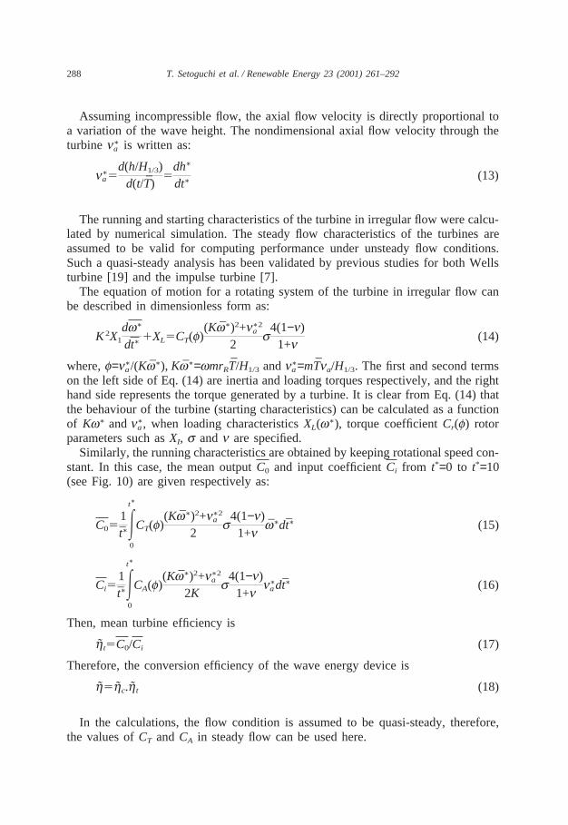
Assuming incompressible flow, the axial flow velocity is directly proportional toa variation of the wave height. The nondimensional axial flow velocity through theturbinen∗
a is written as:
n∗a5
d(h/H1/3)d(t/T̄)
5dh∗
dt∗(13)
The running and starting characteristics of the turbine in irregular flow were calcu-lated by numerical simulation. The steady flow characteristics of the turbines areassumed to be valid for computing performance under unsteady flow conditions.Such a quasi-steady analysis has been validated by previous studies for both Wellsturbine [19] and the impulse turbine [7].
The equation of motion for a rotating system of the turbine in irregular flow canbe described in dimensionless form as:
K2X1
dw∗
dt∗1XL5CT(f)
(Kw̄∗)2+n∗2a
2s
4(1−n)1+n
(14)
where,f=n∗a/(Kw̄∗), Kw̄∗=wmrRT̄/H1/3 andn∗
a=mT̄na/H1/3. The first and second termson the left side of Eq. (14) are inertia and loading torques respectively, and the righthand side represents the torque generated by a turbine. It is clear from Eq. (14) thatthe behaviour of the turbine (starting characteristics) can be calculated as a functionof Kw∗ andn∗
a, when loading characteristicsXL(w∗), torque coefficientCr(f) rotorparameters such asXI, s andn are specified.
Similarly, the running characteristics are obtained by keeping rotational speed con-stant. In this case, the mean outputC0 and input coefficientCi from t*=0 to t*=10(see Fig. 10) are given respectively as:
C051t̄∗E
t∗
0
CT(f)(Kw̄∗)2+n∗2
a
2s
4(1−n)1+n
w̄∗dt̄∗ (15)
Ci51t̄∗E
t∗
0
CA(f)(Kw̄∗)2+n∗2
a
2Ks
4(1−n)1+n
n∗adt̄∗ (16)
Then, mean turbine efficiency is
h̃t5C0/Ci (17)
Therefore, the conversion efficiency of the wave energy device is
h̃5h̃c.h̃t (18)
In the calculations, the flow condition is assumed to be quasi-steady, therefore,the values ofCT andCA in steady flow can be used here.
289T. Setoguchi et al. / Renewable Energy 23 (2001) 261–292
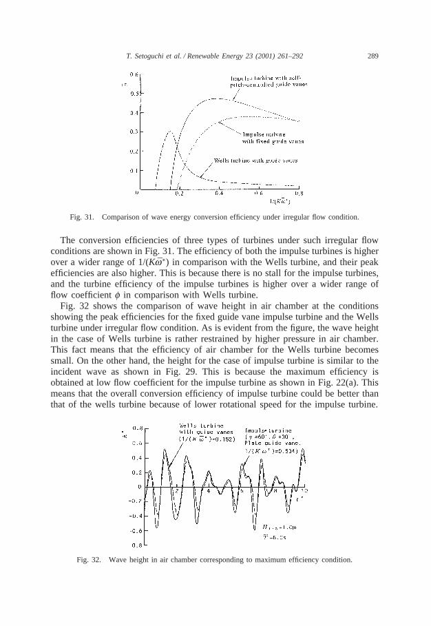
Fig. 31. Comparison of wave energy conversion efficiency under irregular flow condition.
The conversion efficiencies of three types of turbines under such irregular flowconditions are shown in Fig. 31. The efficiency of both the impulse turbines is higherover a wider range of 1/(Kw̄∗) in comparison with the Wells turbine, and their peakefficiencies are also higher. This is because there is no stall for the impulse turbines,and the turbine efficiency of the impulse turbines is higher over a wider range offlow coefficientf in comparison with Wells turbine.
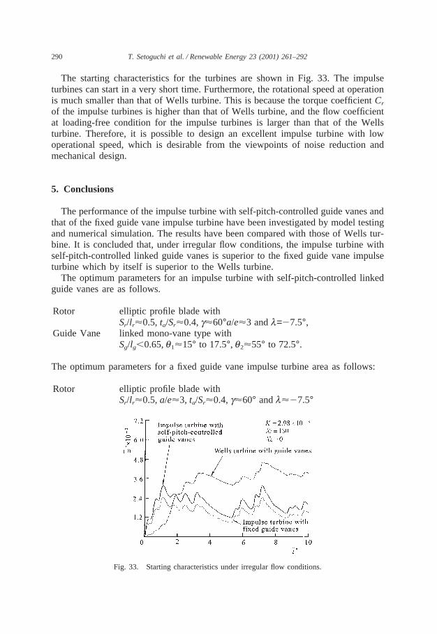
Fig. 32 shows the comparison of wave height in air chamber at the conditionsshowing the peak efficiencies for the fixed guide vane impulse turbine and the Wellsturbine under irregular flow condition. As is evident from the figure, the wave heightin the case of Wells turbine is rather restrained by higher pressure in air chamber.This fact means that the efficiency of air chamber for the Wells turbine becomessmall. On the other hand, the height for the case of impulse turbine is similar to theincident wave as shown in Fig. 29. This is because the maximum efficiency isobtained at low flow coefficient for the impulse turbine as shown in Fig. 22(a). Thismeans that the overall conversion efficiency of impulse turbine could be better thanthat of the wells turbine because of lower rotational speed for the impulse turbine.
Fig. 32. Wave height in air chamber corresponding to maximum efficiency condition.
290 T. Setoguchi et al. / Renewable Energy 23 (2001) 261–292
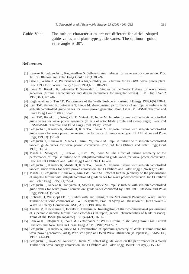
The starting characteristics for the turbines are shown in Fig. 33. The impulseturbines can start in a very short time. Furthermore, the rotational speed at operationis much smaller than that of Wells turbine. This is because the torque coefficientCr
of the impulse turbines is higher than that of Wells turbine, and the flow coefficientat loading-free condition for the impulse turbines is larger than that of the Wellsturbine. Therefore, it is possible to design an excellent impulse turbine with lowoperational speed, which is desirable from the viewpoints of noise reduction andmechanical design.
5. Conclusions
The performance of the impulse turbine with self-pitch-controlled guide vanes andthat of the fixed guide vane impulse turbine have been investigated by model testingand numerical simulation. The results have been compared with those of Wells tur-bine. It is concluded that, under irregular flow conditions, the impulse turbine withself-pitch-controlled linked guide vanes is superior to the fixed guide vane impulseturbine which by itself is superior to the Wells turbine.
The optimum parameters for an impulse turbine with self-pitch-controlled linkedguide vanes are as follows.
Rotor elliptic profile blade withSr/lr<0.5, ta/Sr<0.4,g<60°a/e<3 andl=27.5°,
Guide Vane linked mono-vane type withSg/lg,0.65,q1<15° to 17.5°, q2<55° to 72.5°.
The optimum parameters for a fixed guide vane impulse turbine area as follows:
Rotor elliptic profile blade withSr/lr<0.5,a/e<3, ta/Sr<0.4,g<60° andl<27.5°
Fig. 33. Starting characteristics under irregular flow conditions.
291T. Setoguchi et al. / Renewable Energy 23 (2001) 261–292
Guide Vane The turbine characteristics are not different for airfoil shapedguide vanes and plate-type guide vanes. The optimum guidevane angle is 30°.
References
[1] Kaneko K, Setoguchi T, Raghunathan S. Self-rectifying turbines for wave energy conversion. Proc1st Int Offshore and Polar Engg Conf 1991;1:385–92.
[2] Gato L, Warfield V. Performance of a high-solidity wells turbine for an OWC wave power plant.Proc 1993 Euro Wave Energy Symp 1994;NEL:181–90.
[3] Inoue M, Kaneko K, Setoguchi T, Saruwatari T. Studies on the Wells Turbine for wave powergenerator (turbine characteristics and design parameters for irregular waves). JSME Int J Ser 21988;31(4):676–82.
[4] Raghuanathan S, Tan CP. Performance of the Wells Turbine at starting. J Energy 1982;6(6):430–1.[5] Kim TW, Kaneko K, Setoguchi T, Inoue M. Aerodynamic performance of an impulse turbine with
self-pitch-controlled guide vanes for wave power generator. Proc 1st KSME-JSME Thermal andFluid Engg Conf 1988;2:133–7.
[6] Kim TW, Kaneko K, Setoguchi T, Matsuki E, Inoue M. Impulse turbine with self-pitch-controlledguide vanes for wave power generator (effects of rotor blade profile and sweep angle). Proc 2ndKSME-JSME Thermal and Fluid Engg Conf 1990;1:277–81.
[7] Setoguchi T, Kaneko K, Maeda H, Kim TW, Inouse M. Impulse turbine with self-pitch-controlledguide vanes for wave power conversion: performance of mono-vane type. Int J Offshore and PolarEngg 1993;3(1):73–8.
[8] Setoguchi T, Kaneko K, Maeda H, Kim TW, Inoue M. Impulse turbine with self-pitch-controlledtandem guide vanes for wave power conversion. Proc 3rd Int Offshore and Polar Engg Conf1993;1:161–6.
[9] Maeda H, Setoguchi T, Kaneko K, Kim TW, Inoue M. The effect of turbine geometry on theperformance of impulse turbine with self-pitch-controlled guide vanes for wave power conversion.Proc 4th Int Offshore and Polar Engg Conf 1994;1:378–82.
[10] Setoguchi T, Kaneko K, Maeda H, Kim TW, Inouse M. Impulse turbine with self-pitch-controlledtandem guide vanes for wave power conversion. Int J Offshore and Polar Engg 1994;4(1):76–80.
[11] Maeda H, Setoguchi T, Kaneko K, Kim TW, Inoue M. Effect of turbine geometry on the performanceof impulse turbine with self-pitch-controlled guide vanes for wave power conversion. Int J Offshoreand Polar Engg 1995;5(1):72–4.
[12] Setoguchi T, Kaneko K, Taniyama H, Maeda H, Inoue M. Impulse turbine with self-pitch-controlledguide vanes for wave power conversion: guide vanes connected by links. Int J Offshore and PolarEngg 1996;6(1):76–80.
[13] Richards D, Weishopf FB Jr, Studies with, and testing of the McCormick Pneumatic Wave EnergyTurbine with some comments on PWECS systems, Proc Int Symp on Utilisation of Ocean Waves –Wave to Energy Conversion, ASE, ASCE;1986:80–102
[14] Tanaka M, Kawashima T, Isozaki T, Takehira A. Investigation of the two-dimensional performanceof supersonic impulse turbine blade cascades (1st report, general characteristics of blade cascade).Trans of the JSME (in Japanese) 1981;47(421):1681–9.
[15] Kaneko K, Setoguchi T, Inoue M. Performance of Wells Turbine in sscillating flow. Proc CurrentPractices and New Tech in Ocean Engg ASME 1986;2:447–52.
[16] Setoguchi T, Kaneko K, Inoue M, Determination of optimum geometry of Wells Turbine rotor forwave power generator (Part I), Proc 3rd Symp on Ocean Wave Utilisation (in Japanese), JAMSTEC,1986:141–149.
[17] Setoguchi T, Takao M, Kaneko K, Inoue M. Effect of guide vanes on the performance of a WellsTurbine for wave energy conversion. Int J Offshore and Polar Engg, ISOPE 1998;8(2):155–60.

292 T. Setoguchi et al. / Renewable Energy 23 (2001) 261–292
[18] Hineno M, Yamauchi Y, Spectrum of sea wave, J Soc Nav Arch Japan, (in Japanese),1980;609:160–180.
[19] Inoue M, Kaneko K, Setoguchi T, Raghunathan S. Simulation of starting characteristics of the WellsTurbine. Bull JSME 1986;29(250):1177–82.


