Embed Size (px)
Citation preview

HAL Id: hal-02915271https://hal-mines-paristech.archives-ouvertes.fr/hal-02915271
Submitted on 14 Aug 2020
HAL is a multi-disciplinary open accessarchive for the deposit and dissemination of sci-entific research documents, whether they are pub-lished or not. The documents may come fromteaching and research institutions in France orabroad, or from public or private research centers.
L’archive ouverte pluridisciplinaire HAL, estdestinée au dépôt et à la diffusion de documentsscientifiques de niveau recherche, publiés ou non,émanant des établissements d’enseignement et derecherche français ou étrangers, des laboratoirespublics ou privés.
A real-time unscented Kalman filter on manifolds forchallenging AUV navigation
Théophile Cantelobre, Clément Chahbazian, Arnaud Croux, Silvère Bonnabel
To cite this version:Théophile Cantelobre, Clément Chahbazian, Arnaud Croux, Silvère Bonnabel. A real-time unscentedKalman filter on manifolds for challenging AUV navigation. IEEE International Conference on Intel-ligent Robots and Systems, Oct 2020, Las Vegas, United States. hal-02915271

A real-time unscented Kalman filter on manifolds for challenging AUV navigation
Theophile Cantelobre1, Clement Chahbazian2, Arnaud Croux2, Silvere Bonnabel3
Abstract— We consider the problem of localization andnavigation of Autonomous Underwater Vehicles (AUV) in thecontext of high performance subsea asset inspection missionsin deep water. We propose a solution based on the recentlyintroduced Unscented Kalman Filter on Manifolds (UKF-M) foronboard navigation to estimate the robot’s location, attitude andvelocity, using a precise round and rotating Earth navigationmodel. Our algorithm has the merit of seamlessly handlingnonlinearity of attitude, and is far simpler to implementthan the extended Kalman filter (EKF), which is widely usedin the navigation industry. The unscented transform notablyspares the user the computation of Jacobians and lends itselfwell to fast prototyping in the context of multi-sensor datafusion. Besides, we provide the community with feedback aboutimplementation, and execution time is shown to be compatiblewith real-time. Realistic extensive Monte-Carlo simulationsprove uncertainty is estimated with accuracy by the filter, andillustrate its convergence ability. Real experiments in the contextof a 900m deep dive near Marseille (France) illustrate therelevance of the method.
I. INTRODUCTION
Various industrial fields use Remotely Operated under-water Vehicles (ROV) to inspect critical subsea assets, atgreat cost. Thanks to recent progresses in telemetry and au-tonomous systems, Autonomous Underwater Vehicles (AUV)are currently being developed and deployed as a more cost-efficient and capable solution. One such example is Schlum-berger’s AUV project, displayed in Figure 1 and describedin Section V-A. However, many challenges remain beforeubiquitous adoption of AUVs in industrial use cases. One ofthe most significant challenges is guidance and navigation,as the capacity for the robot to localize itself and correctlysense its environment is pivotal for autonomy.
Given an Autonomous Underwater Vehicle, the goal ofthe present work is to estimate its position, velocity andattitude (kinematic state) as well as the associated confidenceenvelopes, in real-time and in challenging industrial condi-tions where great accuracy is required. Although most highgrade inertial measurements units (IMU) come with built-in(proprietary) navigation softwares, it proves important for theroboticist to develop their own simple yet efficient navigation
This work was supported by Schlumberger-Doll Research, Cambridge,MA (USA).
1Theophile Cantelobre is with INRIA and Mines ParisTech, PSLResearch University, 60 bd Saint-Michel, 75006 Paris, France. Workundertaken during an internship at Schlumberger-Doll [email protected]
2Clement Chahbazian and Arnaud Croux are with Schlumberger-DollResearch, 1 Hampshire St, Cambridge, MA, 02139. [email protected]
3Silvere Bonnabel is with Mines ParisTech, PSL Research Univer-sity, Center for Robotics, 60 bd Saint-Michel, 75006 Paris, France; andUniversity of New Caledonia, Institut ISEA, Noumea, [email protected]
Fig. 1. Schlumberger’s untethered AUV platform used in the experiments.
code to keep grip on the onboard navigation system, whetherit be for fusion with other sensors, or in relation to othermodules such as motion planning, or LiDAR-based mapping.
A. Motivations
In spite of half a century of experience with the ExtendedKalman Filter (EKF), its implementation and tuning in thecontext of high precision inertial navigation still requiresexpertise, that can essentially be found inside companies thatmanufacture high end IMUs. Following the work of Julierand Ulhmann, [1], we believe an implementation based onthe unscented Kalman filter (UKF) is much more desirablefor the roboticist having limited experience in the field ofinertial navigation. Indeed, resorting to the UKF spares thedesigner the computation of Jacobians, as required by theEKF methodology (and the more recent smoothing basedmethods [2]) which can be tedious, error-prone, and lackversatility (changing the model slightly or the sensors mightrequire intensive re-computation).
Despite the EKF being well-established, it was shownto suffer from inconsistent uncertainty estimates, see forexample [3], especially for fusion of IMU and vision.This is an important consideration for practicing roboticists,because a credible uncertainty estimate is crucial for filterperformance, see e.g., Section IV-B.2 and Reference [4].
B. Key contributions
In the present work, to accommodate for the nonlinearityof the rotation matrices encoding the robot’s orientation,we advocate the recently introduced UKF-M methodology,see [5]. The complete solution we present here handlesboth nonlinear state spaces and nonlinear dynamics, whileremaining simple to implement and to grasp. Moreover itis shown to be compatible with the requirements of high
performance real-time subsea inspection in deep water. Ourcontributions include:
1) Developing a complete Inertial Navigation System(INS) based on the UKF-M achieving high accuracy,consistency, and fast runtime performance required forindustrial deep water AUV use cases;
2) Showing the relevance of combining a precise round-Earth kinematic model with the UKF-M in orderto guarantee robustness to dead reckoning, which isessential during dive phases;
3) Developing an end-to-end navigation simulation frame-work using ROS 2 to validate the performance ofthe filter in simulation, and with experimental datacollected using the AUV platform shown in Figure 1;
4) The ROS 2 implementation provides modularity: thesame UKF-M code is seamlessly used for pure simu-lation, in “hardware in the loop” mode, and onboardas well. This approach allows speeding up the devel-opment phase and improves testing methods.
C. Relation to prior literature
The body of work devoted to ROV and AUV navigationis too broad to be covered here, see the surveys [6], [7].However, solutions based on the UKF are scarce [6]. In [8],a modified dual UKF is used for AUV localization. Howeverthe application contrasts with our work owing to the use ofa low-cost IMU: the localization accuracy is hence low, thenavigation model is simplistic and does not account for roundand rotating Earth effects, and experiments are conducted inshallow water (a test tank), where Euler angles are used,which results in singularites [9]. The recent work [10]presents an AUV based navigation system that utilizes theUFK, and proves that the UKF has superior performance tothe EKF. However, the method and the context drasticallydiffer from ours. First, the dynamics rely on a simplifiedphysical model of the robot based on the rotational speed ofthe motors related to the delivered thrusts which by natureis too approximate to compete with high grade IMUs. Thismodel is completed with Xsens MTI IMU which is of muchlower grade than ours, and the orientation estimated bythe Xsens proprietary algorithm is used in the UKF, whichis undesirable at two levels: 1) we want to keep controlover the entire estimation pipeline, and 2) the proprietaryalgorithm delivers highly suboptimal angles estimation asit does not correlate the IMU with other available sensorssuch as GPS, DVL, USBL, and depth, inevitably leading todegraded performance. Finally, the tests are performed at afew meters depth.
The rest of this paper is organized as follows. In Section II,we present the round-Earth system model we use in our filter.In Section III, we present our proposed UKF-M algorithmand discuss its advantages over the industry standard, theEKF. In Section IV, we present the simulation pipeline andthen demonstrate our algorithm’s performance using MonteCarlo simulations using accuracy and consistency metrics.In Section V, we show that the developed filter can run inreal-time using experimental data from the AUV platform.
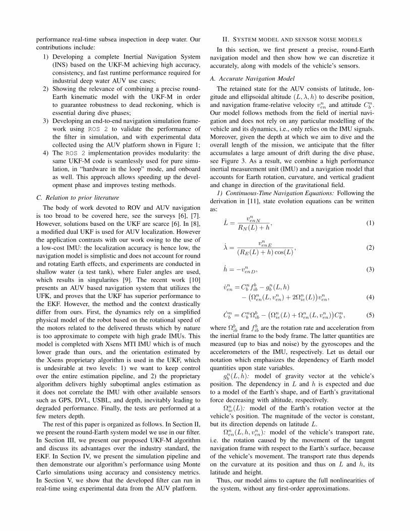
II. SYSTEM MODEL AND SENSOR NOISE MODELS
In this section, we first present a precise, round-Earthnavigation model and then show how we can discretize itaccurately, along with models of the vehicle’s sensors.
A. Accurate Navigation Model
The retained state for the AUV consists of latitude, lon-gitude and ellipsoidal altitude (L, λ, h) to describe position,and navigation frame-relative velocity vnen and attitude Cnb .Our model follows methods from the field of inertial navi-gation and does not rely on any particular modelling of thevehicle and its dynamics, i.e., only relies on the IMU signals.Moreover, given the depth at which we aim to dive and theoverall length of the mission, we anticipate that the filteraccumulates a large amount of drift during the dive phase,see Figure 3. As a result, we combine a high performanceinertial measurement unit (IMU) and a navigation model thataccounts for Earth rotation, curvature, and vertical gradientand change in direction of the gravitational field.
1) Continuous-Time Navigation Equations: Following thederivation in [11], state evolution equations can be writtenas:
L =vnenN
RN (L) + h, (1)
λ =vnenE
(RE(L) + h) cos(L), (2)
h = −vnenD, (3)
vnen =Cnb fbib − gnb (L, h)
−(Ωnen(L, vnen) + 2Ωnie(L)
)vnen, (4)
Cnb = Cnb Ωbib −(Ωnie(L) + Ωnen(L, vnen)
)Cnb , (5)
where Ωbib and f bib are the rotation rate and acceleration fromthe inertial frame to the body frame. The latter quantities aremeasured (up to bias and noise) by the gyroscopes and theaccelerometers of the IMU, respectively. Let us detail ournotation which emphasizes the dependency of Earth modelquantities upon state variables.
gnb (L, h): model of gravity vector at the vehicle’sposition. The dependency in L and h is expected and dueto a model of the Earth’s shape, and of Earth’s gravitationalforce decreasing with altitude, respectively.
Ωnie(L): model of the Earth’s rotation vector at thevehicle’s position. The magnitude of the vector is constant,but its direction depends on latitude L.
Ωnen(L, h, vnen): model of the vehicle’s transport rate,i.e. the rotation caused by the movement of the tangentnavigation frame with respect to the Earth’s surface, becauseof the vehicle’s movement. The transport rate thus dependson the curvature at its position and thus on L and h, itslatitude and height.
Thus, our model aims to capture the full nonlinearities ofthe system, without any first-order approximations.

2) Model Discretization: We now derive the discrete timeequations from the continuous-time model above in viewof our filter’s implementation. The inputs of this discretepropagation step are thus: the previous state, the body framespecific force f bib returned by accelerometers, the rotationrate ωbib returned by gyroscopes (both up to bias and noise),and the time step ∆t. From our experience, the key insightbrought by [11] is to integrate the equations in an orderthat minimizes computations as variables computed can bereused in the next equation. Experimentally, we have foundthe following order to be the best.
In what follows, for each quantity z we denote z(−) thecurrent value, z(+) the propagated value. We denote αbib =ωbib∆t and α = ||αbib||1.
a) Velocity: First, transform the specific force fromthe body to the navigation frame fnib = Cnb f
bib using an
intermediate frame transformation
Cnbdef= Cnb C
b−b
(αbib)−1
2(Ωnie(−) + Ωnen(−))Cnb (−)∆t
Next, calculate vnen(+) in two steps, including the transportand Coriolis terms.
vnen(+) = vnen(−)+∆tfnib + ∆tgnb (L(−), h(−))
−∆t
2(Ωnen(−) + 2Ωnie(−))vnen(−)
(6)
−∆t
2
(Ωnen(vn′en) + 2Ωnie(−))vn′en
where vnen′ is a straightforward integration of Equation (4)
using fnib.b) Longitude, latitude and height: from there, position
is computed using a second order integration method.
h(+) = h(−)− ∆t
2(vnenD(−) + vnenD(+)) (7)
L(+) = L(−) +∆t
2
vnenN (−)
RN (L(−)) + h(−)(8)
+∆t
2
vnenN (+)
RN (L(−)) + h(+)
λ(+) = λ(−) +∆t
2
vnenE(−)
(RE(L(−)) + h(−)) cos(L(−))(9)
+∆t
2
vnenE(+)
(RE(L(+)) + h(+)) cos(L(+))
c) Attitude: Finally, attitude is propagated using thepreviously computed quantities.
Cnb (+) =
(I3 −∆t
(Ωnie(−)−Ωnen(−) + Ωnen(+)
2
))(10)
× Cnb (−)Cb−b+ (αbib)
1See [11] for other notations.
Note that this succession of equations defines a map fsuch that if χ is the kinematic state and u the IMU inputs,χn+1 = f(χn, un,∆t).
B. Sensor Errors
Much of the uncertainty in the model above stems fromthe presence of noise in the IMU’s signals. However, IMUsensor noises are very difficult to model. For this reason,only a posteriori noise models exist, including [12], [13].Based on manufacturer calibration information and an Allanvariance analysis [14] of our hardware, we concluded thata biased, white noise model with covariance matrix Qin wecould compute from the specifications is sufficient, even forhours long missions.
We made similar considerations for the other sensors usedin the mission, that is, Global Positioning System (GPS) atthe surface, Doppler Velocity Log (DVL), depth sensor, andacoustic Ultra Short Base Line (USBL) positioning systemat the bottom.
III. UNSCENTED KALMAN FILTER ON MANIFOLDS FORAUV NAVIGATION
Given a kinematic model and noisy sensor outputs, ourgoal is thus to fuse all the prior information we have aboutour system (the kinematic and sensor models) with the sensordata the robot measures. In our use case, we are faced withtwo problems that make it difficult to apply the commonplaceExtended Kalman Filter (EFK).
1) Rotation-error handling: our state representation doesnot lie in a vector space, but on a manifold owing tothe presence of rotation matrices (or quaternions) thatencode the attitude Cnb .
2) Complexity of the model: because we take into con-sideration an Earth and gravity model, and because ofthe precise integration scheme, deriving the Jacobianof f as required in the EKF methodology is complexand error-prone. Moreover, the slightest model modi-fication requires to re-calculate Jacobians.
For these two reasons, we resort to the method proposedin [5], the Unscented Kalman Filter on Manifolds, as theback-bone of our data-fusion algorithm. The latter is a recentvariant of the UKF as introduced by Julier and Uhlmannin [15], which accommodates for the nonlinear structure ofthe model and of the state space, owed to the presence ofrotation matrices. In this section, we describe the algorithm,the design choices we made and how it handles the twoissues described above.
A. Application of UKF-M to the present problem
In order to use the machinery of UKF-M to accommodaterotation matrices, we naturally define the manifold in whichthe state χ = (L, λ, h, vnen, C
nb ) lives asM = R6×SO3(R).
This choice is also relevant becauseM has a trivial Lie groupstructure, see [16]. The second ingredient of the method isthe choice of a retraction ϕ :M×R9 →M that we define

as
ϕ(χ, ξ) =
L+ ξ1λ+ ξ2h+ ξ3
vnen + ξ4:6
Cnb exp(ξ7:9))
(11)
which leads us to define ϕχ(χ)−1 def=
(χ1:6 −
χ1:6, logSO(3)(χ−17:9χ7:9)
), where we have defined the
expSO(3) and logSO(3) maps on SO3(R) as in [17]. Thisallows one to define an UKF despite the fact the state spaceis a manifold which includes rotation matrices. Indeed, thekey observation is that ϕ−1
χ (χ) ∈ R9 defines a (vector) errorbetween state χ and state χ. Note that, recent works haveadvocated the use of a more sophisticated Lie group fornavigation (and hence a different map ϕ), in the contextof invariant filtering [18]. The potential benefits of such achoice are left for future work, though.
B. Uncertainty Representation
In the UKF-M methodology, the statistical belief aboutthe state is represented as ϕ(χ, ξ) with χ the mean oraverage estimate, and ξ ∼ N (0, P ) a centered Gaussian withcovariance matrix P that reflects statistical dispersion, andwhere ϕ is the chosen retraction, in our case (11). This maybe related to the notion of concentrated Gaussian, see [19],[20], when the state is a Lie group.
C. Proposed Algorithm
We now present our application of the UKF-M algorithmand how it handles model nonlinearities in a derivative-free manner. The main idea behind the UKF-M is to usesigma-points as in the UKF methodology [15] to capture thenonlinearities in the model. These sigma-points statisticallylinearize the model instead of using an analytic expressionof the Jacobian, as required by the EKF. The UKF-Miterates the two following steps over time: (i) propagation(of the distribution through the dynamics), and (ii) update(re-estimation of the distribution in the light of observations).
1) UKF-M: Propagation step: In the UKF-M framework,the mean χ is propagated directly through the system’sequations described in Section II-A.2, as in the standardEKF and in contrast with the canonical UKF methodology.The motivations are as follows: (i) because they do notlie on a vector space, averaging rotation matrices wouldgreatly increase the complexity of the algorithm [21], (ii)with mean propagation separate from covariance propagationin dead reckoning, the filter is more stable. Indeed, in deadreckoning, covariance divergence occurs due to a corollaryof the Schuler effect [11], and in turn degrades the meanpropagation if the canonical UKF methodology is used.
By contrast, to propagate the uncertainty estimate, sigmapoints over state and input variables are used. This presentsthree advantages: (i) it captures second order terms [22],(ii) it avoids error-prone Jacobian calculations [1], and(iii) it eliminates the difficult to compute (or arbitrary [1])propagation noise matrix, essentially eliminating a matrix
hyperparameter. The UKF-M propagation step is summarizedin Algorithm 1.
Algorithm 1: UKF-M: propagation stepInput : χn, Pn, un, ∆t, QinParameters: α, d = dim(χn), λ(d) = d(α2 − 1)// Mean propagationχ+n+1 = f(χn, un,∆t) with f from Section II-A.2;
// State Sigma-point calculationξi = coli(
√d+ λ(d)
√Pn), 1 ≤ i ≤ d;
ξd+i = −coli(√d+ λ(d)
√Pn), 1 ≤ i ≤ d;
// State Covariance propagationεi = ϕ−1
χ+n+1
(f(ϕ(χn, ξi))
), 1 ≤ i ≤ 2d;
P sn+1 =∑2di=1 wiεiε
Ti ;
// Noise Sigma-point calculationξ′i = coli(
√6 + λ(6)
√Qin), 1 ≤ i ≤ 6;
ξ′6+i = −coli(√
6 + λ(6)√Qin), 1 ≤ i ≤ 6;
// Noise Covariance propagationε′i = ϕ−1
χ+n+1
(f(ϕ(χn, ξi))
), 1 ≤ i ≤ 12;
Pnn+1 =∑12i=1 wiε
′iε′Ti ;
Result: χ+n+1, P+
n+1 = P sn+1 + Pnn+1
2) UKF-M: update step: With the introduction of sensornoise from the IMU, the uncertainty obtained during propa-gation (called dead reckoning) grows over time. This can beobserved, for example, in Figure 3. Algorithm 2 describeshow the UKF-M refines the state estimate χ and associateduncertainty P in the light of measurements. In the following,observations are assumed to be of the following form:
∀t ≥ 0, y(t) = h(χ(t)
)+ n(t) (12)
where h is a known map and n is white noise. This mayrepresent DVL, acoustic positioning, and more generally allreadings from sensors of the AUV.
As is usual in data fusion, the state vector can be extendedto include parameters such as model biases. This allows easycalibration of IMU biases, for example, see Figure 5.
D. Numerical Aspects
While less accurate and consistent than the UKF [3][22],the EKF still prevails in the navigation industry because theformer is considered as more challenging numerically.
1) Runtime performance: A straightforward applicationof the UKF methology implies running Algorithm 1 at highfrequency (typically 100 Hz), with 2d + 1 forward modelevaluations and a matrix square root computation. This isoften considered prohibitive on standard hardware. However,we show that in the context of industrial-grade navigationsystems for AUVs, the UKF-M is a feasible solution. Weobserved a 40× margin compared to real-time, with fullstate updates. Our runtime evaluations are summarized inTable I. The experiments were executed on a Intel Corei7-8850H CPU (2.60GHz) akin to embedded Intel NUCboards. We believe it is a contribution of this work to therobotics community to have shown that the UKF-M’s simpler

Algorithm 2: UKF-M: update step
Input : χ+n+1, P+
n+1, un+1, hParameters: α, d = dim(χn), λ(d) = d(α2 − 1)// Sigma-point calculation
ξi = coli(√d+ λ(d)
√P+n+1), 1 ≤ i ≤ d;
ξd+i = −coli(√d+ λ(d)
√P+n+1), 1 ≤ i ≤ d;
// Mean and sigma-point predictiony0 = h(χ+
n+1);yi = h(ϕ
(χ+n+1, ξi
)), 1 ≤ i ≤ 2d;
// Mean calculation
y =∑2di=0 w
si yi;
// Covariance calculation
Pyy =∑2di=0 w
ci (yi − y)(yi − y)T ;
// Cross-covariance calculation
Pχy =∑2di=1 w
ci ξi(yi − y)T ;
// Covariance updateK = PχyP
−1yy ;
Pn+1 = P+n+1 −KPyyKT ;
// Mean updateχn+1 = ϕ
(χ+n+1,K(yn+1 − y)
);
Result: χn+1, Pn+1
implementation can actually be leveraged in practice withoutsacrifying runtime performance.
TABLE IRUNTIME PERFORMANCE.
Mission type Mission length (s) fs IMU (s) Runtime (s)Full navigation 1945 100 Hz 45.6Full navigation 1945 10 Hz 4.6Propagation only 1945 100 Hz 32.4Propagation only 1945 10 Hz 3.3
2) Rotation matrix stability: In the navigation and aero-nautics literature and industries, it is customary to usequaternions in place of rotation matrices2. However, the useof rotation matrices is common among roboticists. We foundthat by applying Gram-Schmidt normalization to Cnb whennecessary, our performance was indistinguishable from thatof a quaternion-based system.
IV. REALISTIC NUMERICAL EXPERIMENTS
In AUV applications, especially subsea asset inspectionin the Oil & Gas industry where robots may operate indeep water, ground truth is very costly - if not impossible- to obtain, especially during the design stage. We thusmade extensive use of a simulation framework built on theROS 2 [24] middleware to develop and test the algorithm.This allows us to assess accuracy, consistency, and runtimeperformance of the filter.
2For an UKF implementation of attitude-only estimation using quater-nions, see the USQUE algorithm in [23].
A. Simulation pipeline
As part of the design and the implementation of thenavigation algorithm we presented above, we developed anend-to-end simulation pipeline. From a concise descriptionof the trajectory, it simulates the vehicle’s sensors and,using ROS 2 as a middleware, runs the navigation algorithmagainst this data. Our simulation framework is composed ofROS 2 nodes, and can be presented in four layers:
1) Ground truth trajectory generation, based on the open-source GNSS INS Sim package3;
2) Sensor simulation nodes, which use the ground truthtrajectories to generate sensor output, taking into con-sideration sensor visibility aspects;
3) UKF-M node, which estimates the vehicle’s state andassociated uncertainty from simulated sensor output;
4) Finally, real-time visualization and diagnostics relyingon a Postgres database interfaced with a Grafanadashboard.
This approach has several advantages including: (i) it ismodular and interactive: it can easily be extended to includenew sensors, physical model or vehicle behaviors or decisionmaking capabilities; (ii) it simulates many of the challengesof real-time navigation, such as delays and message loss; (iii)it is compatible with Hardware-in-the-loop simulation in aDigital avatar in a lab or testing onboard a vehicle, suchas onboard Schlumberger’s Sabertooth platform described inSection V-A.
B. Monte Carlo Experiments and Evaluation Metrics
In order to rigorously evaluate our model and our algo-rithm, we simulated the navigation system presented aboveon a realistic inspection-type mission, using Monte Carlosimulations. We draw N different noise realizations over theinput data (IMU, depth sensor, GPS, DVL and USBL) andrun the algorithm against these N realizations. The output ofthe different runs χi(t) allow us to evaluate the algorithm’sperformance according to two criteria: its accuracy and itsconsistency. These simulations were run on a variant of theabove pipeline compatible with parallel simulation, usingGNU Parallel [25].
The metrics we use to assess filter’s performance are:1) Accuracy through Standard Deviation: We measure
the dispersion of the different runs, i.e. the risk we takeby accepting to use one of the trajectories as our meantrajectory. For this, we denote σN (t) the standard deviationof the different runs’ estimates at time t.
2) Consistency through Normalized Estimation ErrorSquared (NEES): One of our algorithm’s desirable propertiesis the quality of its uncertainty estimate. This is paramountas it impacts the quality of the estimation later during themission for the two following reasons. First, as presentedby Y. Bar-Shalom, in [4], “wrong covariances yield wronggains”, which in turn may degrade performance. This is espe-cially true in navigation, where it is customary to propagateat high frequency (typically at f IMU
s = 100 Hz) and update
3https://github.com/Aceinna/gnss-ins-sim

less frequently (typically at fGPSs = 1 Hz). Second, theuncertainty estimate P is a quantity that can be used asinput to other algorithms, especially for motion planningand resulting decision making on board the vehicle (forexample, to safely approach subsea infrastructure during aninspection mission). Finally, uncertainty may also be usedwhen correlating feeds from imaging sensors [26], and ourAUV is also equipped with LiDAR for survey purposes.
We define the Normalized Estimation Error Squared(NEES) for each trajectory χi(t) and uncertainty estimateP i(t), comparing the estimated uncertainty to the estimationerror [4][27]. Formally, if ξG(t) is the ground truth trajectoryand ξi(t) is an estimated trajectory with associated uncer-tainty P i(t), then εi(t) = ϕ−1
χG(t)
(χi(t)
)is the estimation
error. The NEES is defined by:
νi(t)def=
1
dεi(t)TP i(t)−1εi(t) (13)
We can then define the Average NEES (ANEES) over thedifferent trajectories, ν(t)
def= 1
N
∑Nk=1 ν
i(t).To ensure we have a reliable uncertainty estimate, ν(t)
should be around 1: if ν > 1, the uncertainty is overesti-mated; otherwise, it is underestimated.
TABLE IISENSOR VISIBILITY ON INSPECTION MISSION
Phase IMU GPS Depth DVL USBLCalibrate 3 3 7 7 7Dive 3 7 3 7 7Survey 3 7 3 3 3
Fig. 2. Longitude error (m) during the calibration phase. Despite thecalibration process, the estimates are stable and the uncertainty well-estimated.
C. Simulation Mission Design
We evaluated our model and algorithm against a realisticinspection mission, a dive and survey mission (DAS). The
Fig. 3. Longitude error (m) during the dive phase. Note that the uncertaintyin the estimate is well predicted by
√P (t).
Fig. 4. Longitude error (m) during the survey phase after large drift hasbeen accumulated in the dead reckoning dive phase. This illustrates thefilter’s convergence properties owed to the consistent uncertainty estimationduring dead reckoning.
mission can be divided into three successive parts describedbelow. Conservative hypotheses are assumed with respect tosensor visibility and performance, summarized in Tables IIand III respectively. These characteristics reflect those of therobot displayed in Figure 1.
1) Surface calibration: At the surface, the vehicle cali-brates its IMU biases by executing figure-eights, with onlyGPS visible. Note that no special behavior is imparted to thefilter during this calibration phase, it runs identically to theother phases.
2) Dive: Dive from the surface to 1200 meters depth ata 80 degree incline. Only the depth sensor is available.
3) Survey: At 1200 meters depth, level and execute ahigh-altitude survey over equipment in a lawnmower pattern.Depth, DVL and USBL sensors are then all available.
D. Results
To analyze the performance of our framework, we use thetwo metrics defined in Section IV-B:

Fig. 5. Accelerometer bias estimate (m/s2) during the calibration phase.The horizontal red dashed line is the true bias parameter 0.004m.s−2, andwe see it is fully recovered. Note that the convergence
√P (t) to 0 can be
used to mark the end of the calibration phase.
Fig. 6. NEES over the mission. At the beginning of the mission, uncertaintyis overestimated but the NEES rapidly converge towards 1. At each changein navigation regime, the NEES becomes very large for a few seconds, thetime for the filter to converge. It quickly converges back to 1 (red dashedline). The black curve is the ANEES and the grey envelope the dispersionof the NEES trajectories as defined in Section IV-B.2, over N = 48 runs.
• to evaluate consistency: in Figure 6, we compare ν(t) to1 and verify that the spread of the νi(t) are reasonable;
• to evaluate accuracy: in Figures 2-4, we show the1−σN (t) envelope for the different estimated trajec-tories, and compare them to our estimated uncertainty√P i(t)4. In these figures, the grey envelope is between
±σN (t) and the black lines are the estimated covariance√P (t), for N = 48 runs.
The results illustrate several desirable properties of thealgorithm:
1) Overall performances: Figures 2-6 show that our filterachieves metric accuracy and is consistent, on a realistic deepwater inspection-type mission, including an (auto) calibration
4Note that although the P i(t) are date-dependent, in practice theirdispersion is negligible, so any P i(t) can be used.
phase where IMU biases are recovered.2) Robustness to dead-reckoning: Figure 3 shows that the
accumulated dispersion is only 200 m after 15 minutes ofdead reckoning of diving.
3) Convergence property: Figure 4 illustrates filter con-vergence: the filter recovers the correct position thanks toDVL and USBL updates, despite dispersion incurred duringdead reckoning dive. This also emphasizes the importanceof a consistent uncertainty estimate which yields correctKalman gains. Note that these results are obtained usingnominal noise models, without so-called “robust learning”or “stabilizing noise” [1] which helps the filter to convergeand combat the nonlinearities but ultimately degrades per-formance, since it is based on erroneous noise statistics.
4) Sensor bias integration: Figure 5 shows how sensorbiases can be observed with great confidence executinga simple maneuver during a short period of time. Moreimportantly, one can use the convergence of the bias un-certainty (the
√P (t) envelope) to detect the bias estimate’s
convergence.5) Consistency: Finally, Figure 6 shows that the ANEES
is reliably close to 1 during the mission, except when thereare transitions in sensor visibility. The ability of the filterto very accurately convey its uncertainty is key notably formotion planning during inspection and maintenance.
TABLE IIISENSOR CHARACTERISTICS
Sensor fs (Hz) Noise model Bias model
Gyroscope 100 Hz 0.012 deg/√hr 2 deg/hr
Accelerometer 100 Hz 0.0141 m.s−1.hr−1/2 4.10−3m/s2
Depth 1 Hz 1.0 m -GPS 1 Hz 2 m -DVL 1 Hz 5 mm/s -USBL 1/60 Hz 5 m, 5 m, 0.1 m -
V. EXPERIMENTAL VALIDATION
In order to show that the INS presented in this work can beused onboard an AUV, we evaluated it against data collectedin the field by Schlumberger with the AUV displayed inFigure 1 and described below. Our experiments show thatwithout algorithm adaptation, we obtain a credible estimateof the AUV’s position.
A. Experimental Platform & Data Collection
The platform used to collect the data is an untetheredAUV, developed by Schlumberger within a wider multi-agent autonomy system for subsea asset inspection. Basedon Saab’s Sabertooth platform, the AUV features a standardunderwater navigation sensor suite including: a high-gradeIMU, Doppler Velocity Log (DVL), depth sensor, GPS, andUltra-Short Baseline (USBL) acoustic postioning system.Sensors’ characteristics are summarized in Table III.
The AUV was used to capture IMU, GPS, DVL, USBLand depth data from the sensor suite in order to evaluate theframework presented above. The mission was executed off

the coast of La Ciotat (France) and is similar to the one usedfor simulation. In particular, it includes a dive as well as asurvey at around 900 meters depth.
Fig. 7. Estimated trajectory on experimental data captured using Schlum-berger’s AUV. USBL used in the update step are materialized (red crosses).
B. Results & Discussion
Runnning against this data, we showed that our INSsystem was capable of reproducing the performance achievedin simulation, in real-time, and with comparable performanceto the simulation results.
Figure 7 shows the longitude estimate over an extractof the estimated trajectory, during the survey phase at thearound 900 meters depth. During that segment, the IMU,DVL, and USBL sensors are available. In Figure 7, USBLdatapoints are represented by red crosses. They show thatdespite the filter being initialized erroneously, the filterconverges through USBL and DVL updates.
VI. CONCLUSION
Our work shows that our UKF-M-based navigation solu-tion can be used in real-time, while attaining high accuracyand consistency on challenging, sensor-denied missions. Fur-thermore, we showed that it is robust to dead-reckoning andto sensor biases. These results have been shown to hold insimulation and on experimental data from various sensors(high-grade IMU, DVL, and USBL) in the context of a real,challenging 900 m deep mission.
In future work we plan to (1) integrate perception-basedupdates to the navigation system, and (2) develop manoeu-vres to re-calibrate underwater.
REFERENCES
[1] S. Julier and J. Uhlmann, “Unscented Filtering and Nonlinear Estima-tion,” Proc. IEEE, vol. 92, pp. 401–422, Mar. 2004.
[2] M. F. Fallon, M. Kaess, H. Johannsson, and J. J. Leonard, “EfficientAUV navigation fusing acoustic ranging and side-scan sonar,” in2011 IEEE International Conference on Robotics and Automation,(Shanghai, China), pp. 2398–2405, IEEE, May 2011.
[3] G. P. Huang, A. I. Mourikis, and S. I. Roumeliotis, “Analysis andimprovement of the consistency of extended Kalman filter basedSLAM,” in 2008 IEEE International Conference on Robotics andAutomation, (Pasadena, CA, USA), pp. 473–479, IEEE, May 2008.
[4] Y. Bar-Shalom, X.-R. Li, and T. Kirubarajan, Estimation with Appli-cations to Tracking and Navigation. New York, USA: John Wiley &Sons, Inc., 2001.
[5] M. Brossard, A. Barrau, and S. Bonnabel, “A Code for UnscentedKalman Filtering on Manifolds (UKF-M),” in 2020 InternationalConference on Robotics and Automation (ICRA), IEEE, 2020.
[6] J. C. Kinsey, R. M. Eustice, and L. L. Whitcomb, “A SURVEY OFUNDERWATER VEHICLE NAVIGATION: RECENT ADVANCESAND NEW CHALLENGES,” p. 12.
[7] L. Paull, S. Saeedi, M. Seto, and H. Li, “AUV Navigation andLocalization: A Review,” IEEE J. Oceanic Eng., vol. 39, pp. 131–149, Jan. 2014.
[8] G. C. Karras, S. G. Loizou, and K. J. Kyriakopoulos, “On-line stateand parameter estimation of an under-actuated underwater vehicleusing a modified Dual Unscented Kalman Filter,” in 2010 IEEE/RSJInternational Conference on Intelligent Robots and Systems, (Taipei),pp. 4868–4873, IEEE, Oct. 2010.
[9] P. Allgeuer and S. Behnke, “Fused angles: A representation of bodyorientation for balance,” in 2015 IEEE/RSJ International Conferenceon Intelligent Robots and Systems (IROS), (Hamburg, Germany),pp. 366–373, IEEE, Sept. 2015.
[10] B. Allotta, A. Caiti, R. Costanzi, F. Fanelli, D. Fenucci, E. Meli,and A. Ridolfi, “A new AUV navigation system exploiting unscentedKalman filter,” Ocean Engineering, vol. 113, pp. 121–132, Feb. 2016.
[11] P. D. Groves, Principles of GNSS, inertial, and multisensor integratednavigation systems. GNSS technology and application series, Boston:Artech House, 2nd ed ed., 2013. OCLC: ocn820530994.
[12] R. J. Vaccaro and A. S. Zaki, “Statistical Modeling of Rate Gyros,”IEEE Trans. Instrum. Meas., vol. 61, pp. 673–684, Mar. 2012.
[13] “IEEE Standard Specification Format Guide and Test Procedure forSingle-Axis Interferometric Fiber Optic Gyros,” tech. rep., IEEE,1997.
[14] D. Allan, “Time and Frequency (Time-Domain) Characterization,Estimation, and Prediction of Precision Clocks and Oscillators,” IEEETrans. Ultrason., Ferroelect., Freq. Contr., vol. 34, pp. 647–654, Nov.1987.
[15] S. J. Julier and J. K. Uhlmann, “New extension of the Kalman filter tononlinear systems,” in Signal Processing, Sensor Fusion, and TargetRecognition VI (I. Kadar, ed.), vol. 3068, pp. 182 – 193, InternationalSociety for Optics and Photonics, SPIE, 1997.
[16] M. Brossard, S. Bonnabel, and J.-P. Condomines, “Unscented Kalmanfiltering on Lie groups,” in 2017 IEEE/RSJ International Conferenceon Intelligent Robots and Systems (IROS), (Vancouver, BC), pp. 2485–2491, IEEE, Sept. 2017.
[17] T. D. Barfoot, State Estimation for Robotics. Cambridge: CambridgeUniversity Press, 2017.
[18] A. Barrau and S. Bonnabel, “The Invariant Extended Kalman Filter asa Stable Observer,” IEEE Trans. Automat. Contr., vol. 62, pp. 1797–1812, Apr. 2017.
[19] Yunfeng Wang and G. Chirikjian, “Error propagation on the Euclideangroup with applications to manipulator kinematics,” IEEE Trans.Robot., vol. 22, pp. 591–602, Aug. 2006.
[20] G. Bourmaud, R. Mgret, M. Arnaudon, and A. Giremus, “Continuous-Discrete Extended Kalman Filter on Matrix Lie Groups Using Concen-trated Gaussian Distributions,” J Math Imaging Vis, vol. 51, pp. 209–228, Jan. 2015.
[21] M. Moakher, “Means and Averaging in the Group of Rotations,” SIAMJ. Matrix Anal. & Appl., vol. 24, pp. 1–16, Jan. 2002.
[22] F. Gustafsson and G. Hendeby, “Some Relations Between Extendedand Unscented Kalman Filters,” IEEE Trans. Signal Process., vol. 60,pp. 545–555, Feb. 2012.
[23] J. L. Crassidis and F. L. Markley, “Unscented Filtering for SpacecraftAttitude Estimation,” Journal of Guidance, Control, and Dynamics,vol. 26, pp. 536–542, July 2003.
[24] M. Quigley, B. Gerkey, K. Conley, J. Faust, T. Foote, J. Leibs,E. Berger, R. Wheeler, and A. Ng, “ROS: an open-source RobotOperating System,” p. 6.
[25] P. D. Hanlon and P. S. Maybeck, “GNU Parallel - The Command-LinePower Tool,” login: The USENIX Magazine, no. 2, pp. 42–47, 2011.
[26] M. Brossard, A. Barrau, and S. Bonnabel, “AI-IMU Dead-Reckoning,”arXiv:1904.06064 [cs, stat]. Accepted in IEEE Transactions on Intel-ligent Vehicles., Apr. 2020. arXiv: 1904.06064.
[27] X. R. Li, Z. Zhao, and V. P. Jilkov, “Practical Measures and Test forCredibility of an Estimator,”