Embed Size (px)
Citation preview

2958 R. V. TOWNEND Vol. 50
2. From the data obtained we have calculated the osmotic pressures, the activities of the solute and solvent, the activity coefficients and various changes in free energy accompanying change in concentration.
3. For all concentrations the magnitude of these solution values is greater for solutions of sodium bromide than for solutions of potassium iodide.
IOWA CITY, IOWA
[CONTRIBUTION FROM THE CHEMISTRY LABORATORY OF THE JOHNS HOPKINS UNIVERSITY ]
A NEW METHOD FOR MEASURING OSMOTIC PRESSURE1nZ BY R. V. TOWND
RECEIVED AUGUST 2, 1928 P ~ L I S R B D NOVEMBER 6, 1928
Introduction In the past the study of osmotic pressure has been hampered by the
experimental difficulties involved in making exact measurements. At least partly for this reason, the possibilities of osmotic pressure as a means for investigating the nature of solutions of electrolytes have been largely overlooked. The subject is treated briefly in many textbooks of chem- istry, although its fundamental importance in other lines, such as plant and animal nutrition, has long been recognized by botanists and others. As a means for determining the activity of dissolved substances i t ranks with such methods as vapor pressure lowering, freezing point lowering, and boiling point raising. 145th the exception of vapor pressure measure- ments] i t is the only method of directly measuring activity a t any and all temperatures. The osmotic method also has certain advantages over that which depends on the estimation of difficultly soluble substances in the presence of other salts. In the latter case i t is necessary to make certain assumptions, such as the “ionic strength principle,” whereas this is un- necessary in the case of the osmotic method. Moreover, the fact that a thousandth molal potassium chloride solution has a freezing point lowering of about 0.00368”, whereas the same solution has an osmotic pressure of about 36 mm., indicates clearly that as a means for investigating dilute solutions it would be of unsurpassed value provided certain experimental difficulties could be overcome.
The Measurement of Osmotic Pressure The ordinary method for measuring osmotic pressure and the only one
which has so far given satisfactory results consists in the use of a porous 1 In memory of Ira Remsen. 2 The substance of this paper was presented by the author to the Board of Uni-
versity Studies of The Johns Hopkin’s University as part of the requirement for the c‘t- gree of Doctor of Philosophy.
Nov., 1928 MEASUREMENT OF OSMOTIC PRESSURE 2959
clay cell, which acts as a support for a copper ferrocyanide membrane. The solution is placed on one side of the cell, a suitable manometer at- tached and the equilibrium pressure determined when pure solvent is placed in contact with the other side of the membrane. The method has been refined so as to give reliable results with solutes of high molecular weight but up to the present it has not been applicable to solutions of electrolytes, on account of the difficulty in obtaining suitable membranes which would be impermeable to the ions.
The present method makes use of two general properties of liquids which are not ordinarily considered: first, that changing the pressure on a liquid surface changes its vapor pressure, and, secondly, that liquids possess an internal pressure or cohesion force so that (in the absence of excess dis- solved gases) i t is possible to place a tension on the two ends of a column of l i q ~ i d . ~
Outline of the Method In the method to be described here, the solution to be measured-for
example a salt solution-is placed in contact with its vapor. Some of the pure solvent is also placed in contact with the vapor. Since the vapor pressure of the solution is less than the vapor pressure of the pure solvent a t the same temperature, in the case mentioned, water vapor will distil from the pure solvent into the solution. It is seen that the vapor phase may be regarded as a perfect semi-permeable membrane permitting the passage of the molecules of solvent only.
In order to permit the measurement of the osmotic pressure the liquid water is located within the capillaries of a thin porous plate. The capil- laries are of sufficient size to permit the liquid water to pass readily to the surface of the plate, but so small that the maximum capillary rise is somewhat greater than the maximum osmotic pressure to be measured. Below the plate is a quantity of liquid water and below this a column of mercury. The weight of the water and mercury places a tension on the water a t the surface of the plate. At equilibrium this force (corrected for any difference in heights between the water and solution) equals the osmotic pressure of the solution. The equilibrium point is determined by measuring the rates of distillation from the plate to the solution under different tensions. These rates are plotted against the corresponding tensions. The osmotic pressure, which corresponds to the tension a t zero distillation, is obtained from the curve by extrapolating to zero.
There are several experimental details mentioned below which, in the course of working out this method, were found to be necessary for success. From the large amount of work carried out in this Laboratory on vapor pressure, it was known that in order to obtain a satisfactory distillation
See also Washbum, J. Am. Ceram. SOC., 1,29 (1918).
2960 R. V. TOWNEND Vol. 50
from (or into) the surface of a liquid, the system must be practically air- free.
In order to insure absolute uniformity (both of temperature and com- position) throughout the solution a t all times, gentle stirring was neces- sary. Violent agitation a t the surface was to be avoided, as it might give high results due to the fact that potassium chloride is negatively adsorbed a t the surface of water solutions.
The porous disk involved considerable experimentation in order to secure the required porosity, as pointed out above. In addition, the disk must be mechanically supported to withstand the stress applied and all surfaces must be thoroughly wetted by the liquid.
At 25" the vapor pressure of water changes approximately 1.4 mm. per degree, while a 0.001 M solution lowers the vapor pressure by approximately 0.00074 mm. Thus i t is seen that a drop in temperature of about 0.00053" has the same effect on the vapor pressure as a 0.001 molal solution.
Since in the process of removing the air from the system, the con- centration of the solution was changed by an unknown amount, the solutions were analyzed after the measurements were completed. These analyses were made by means of the Zeiss interferometer, after the in- strument had been calibrated against solutions of the same salt of known concentration. In the case of the most dilute solution, the total amount of solid used was less than five milligrams and it was necessary to con- centrate a portion of the solution by evaporation before a satisfactory reading could be obtained on the interferometer.
By this method the measurements of osmotic pressure are made on air-free solutions. Since the solubility of air in water under ordinary conditions is nearly 0.001 M, this may well affect the measurements which are made on dilute solutions, in which the solute is present to only a fraction of this amount. In the majority of instances this factor has been entirely neglected.
Temperature control is of primary importance.
Details of the Apparatus The thermostat used in this work was a cylindrical copper tank, sixteen inches high
and of the same diameter. It was covered on the sides and bottom with a layer of as- bestos. Vigorous circulation was effected by means of a three and one-half inch pro- peller with suitable baffles. No temperature difference could be detected with a Beck- mann thermometer in various parts of the bath. The usual heating lamp in series with a lamp bank of nominally 300 volts, and coil carrying tap water for cooling were used. It was found necessary to shield the contents of the thermostat from strong light during the course of a run, due to local superheating. Consequently the windows and top were covered during these periods.
The thermoregulator was of the toluene-mercury type constructed as follows. Twelve feet of thin, one-quarter inch diameter copper tubing was coiled into a helix about twelve inches in diameter. One end was squeezed tightly together- and soldered
Nov., 1928 MEASURBMENT OF OSMOTIC PRESSURE 2961
along the seam. To the other end a four-inch length of brass tubing of slightly larger diameter was fitted carefully and soldered. The other end of the brass tubing was attached to the glass part of the regulator by means of a "soldered joint." This was made as follows: the brass tube was reamed out sufficiently to allow the glass to slide inside for a distance of about an inch. The inside of the brass tube was "tinned" and a slight excess of solder melted into the inside, The glass was roughened slightly by rub- bing with fine emery paper, carefully cleaned and dried. After having coated the sur- face of the roughened part with a layer of platinum (produced by evaporating a solu- tion of platinum chloride on this surface and decomposing the chloride by heating to dull redness), the two pieces were heated to about the same temperature and pushed together.
Under the best conditions the regulator de- scribed held the temperature of the bath suffi- ciently constant so that no movement of the mercury of the Beckmann thermometer was de- tected. The room temperature was held not more than two or three degrees from the tem- perature of the bath and in particular sudden fluctuations of temperature were avoided. It was found advantageous to make the measure- ments a t night and in most instances this was done. . I n the experiments the bath vaned slightly in temperature but not over two or three thousandths of a degree. As a matter of fact, due to the lag in registering, it is question- able whether the Beckmann readings are much more reliable than this. As wilk be shown later, this figure does not represent the difference in temperature between the solvent and solution, which is theimportant point. The temperature of the bath was determined by comparison with a thermometer standardized by the Bureau of Standards to 0.02 '.
The porous disk was composed of equal parts by weight of the special clay used in this Laboratory for making osmotic pressure cells
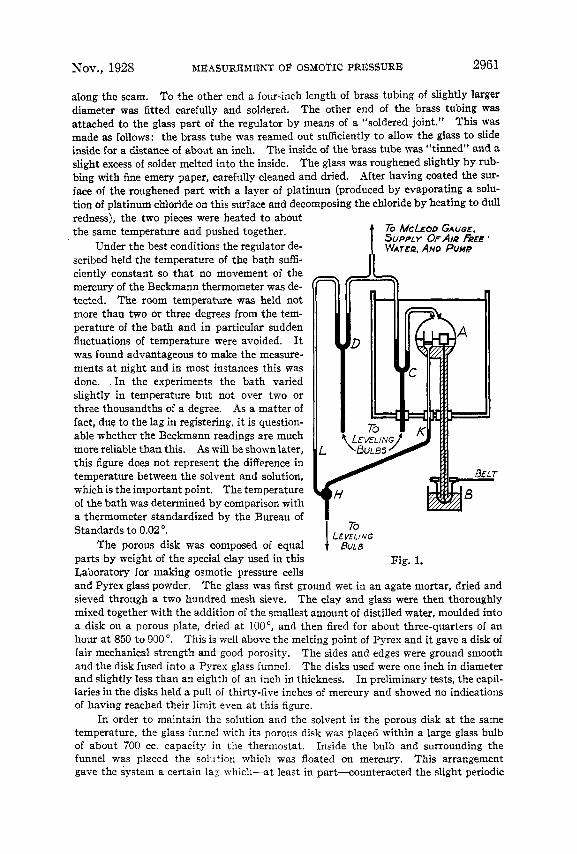
To MCLEOD GAUGE. SUPPLY OF AIR FREE ' T IVh'ArEQ. AND PUUP
I1
I LEVV;VG To
Fig. 1.
and Pyrex glass powder. The glass was first ground wet in an agate mortar, dried and sieved through a two hundred mesh sieve. The clay and glass were then thoroughly mixed together with the addition of the smallest amount of distilled water, moulded into a disk on a porous plate, dried at loo", and then fired for about three-quarters of an hour a t 850 to 900'. This is well above the melting point of Pyrex and it gave a disk of fair mechanical strength and good porosity, The sides and edges were ground smooth and the disk fused into a Pyrex glass funnel. The disks used were one inch in diameter and slightly less than an eighth of an inch in thickness. In preliminary tests, the capil- laries in the disks held a pull of thirty-five inches of mercury and showed no indications of having reached their limit even a t this figure.
In order to maintain the solution and the solvent in the porous disk at the same temperature, the glass funnel with its porous disk was placed within a large glass bulb of about 700 cc. capacity in the thermostat. Inside the bulb and surrounding the funnel was placed the solution which was floated on mercury. This arrangement gave the system a certain la2 which-at least in part-counteracted the slight periodic
R. V. TOWNEND Vol. 50 2962
changes in bath temperature incident to thermoregulator control and furnished good thermal contact between the solvent and solution.
The general arrangement of the apparatus is indicated in Fig. 1. A represents the bulb in the thermostat which holds the solution and the small glass funnel with its porous disk. Just to the right of the funnel is shown the stirrer, consisting of a small platinum paddle driven as indicated through a mercury seal a t B.
From beneath the porous plate, a two millimeter capillary extended to a small bulb at H. This capillary contained the column of water which was placed under tension by the mercury in contact with it a t K. In the absence of air no trouble whatever was experienced in getting the water to adhere to the plate, or the mercury to the water, Bulb H was connected by means of a length of rubber tubing to an ordinary leveling b d b which was open to the atmosphere. This permitted adjustment of the tension by moving the leveling bulb up or down by means of a screw.
Also from H a capillary tube extended vertically upward, giving a direct measure- ment of the zero reading of the mercury meniscus a t L. The upper part of this tube was completely evacuated and closed off by the mercury Y at D. By using the same size of tubing a t K and L, no correction for capillary depression was necessary.
A bulb of 300 cc. capacity was sealed into the system to provide a volume into which the vapor of the solution could be expanded. Another bulb containing air-free water was also sealed into the apparatus. This served as a source of water vapor to sweep the air from the system or to fill the space beneath the porous disk with water vapor. In the absence of air, it was a simple matter to distil water from one part of the system to another by a slight difference in temperature, Neither of these two bulbs is shown on the diagram.
The readings of the heights a t K and at L and of the surface of the solution in A were made by means of a cathetometer and a standard meter scale mounted vertically a t a convenient distance.
Method of Procedure Between 200 and 230 cc. of freshly redistilled water was collected in a
Pyrex Erlenmeyer flask fitted with a cork stopper covered with tin foil. After cooling, the flask and water were weighed and an amount of pure salt was added to give approximately the desired concentration. This solu- tion was run into a round Pyrex bulb of about 300 cc. capacity provided with a glass stopcock on one side. To the opposite side of the bulb, an ordinary mercury leveling bulb was attached by means of a rubber tube and about four inches of glass tubing. The height of mercdry was ad- justed so that the mercury came just to the glass bulb and the rubber tubing was closed with a screw clamp. The solution was then readily introduced by partially evacuating the bulb and connecting a glass funnel to the outer end of the glass stopcock by means of a short piece of clean rubber tubing. On opening the stopcock the solution was quickly drawn in.
The bulb was tilted a t a slight angle and the solution brought to the boiling point by placing a small flame underneath. The solution was allowed to simmer for some minutes with the stopcock left open. The elimination of air from the solution is a direct function of t he time and it was found advantageous to extend this simmering period for an hour or even longer. The solution was then heated to vigorous boiling for a
Nov., 1928 MEASUREMENT OF OSMOTIC PRESSURE 2963
moment or two in order to expel1 completely the air from the vapor space above the liquid, and while still boiling the mercury was allowed to run in rapidly from beneath, forcing the solution up past the stopcock, which was a t once closed. After allowing the whole to cool, a short piece of rubber tubing was attached and sufficient mercury added from a small pipet to displace the solution above the stopcock and completely fill the rubber tubing. One end of a capillary glass tube about nine inches long was then forced into the rubber connection so that the mercury went part way up the capillary. The other end of the glass tube had previously been drawn out and the tip bent up a t an angle.
In order to introduce the solution into the apparatus the system was evacuated completely and filled with water vapor to prevent the sudden evaporation of the first solution added. The tip of the capillary tubing was placed beneath the mercury, which sealed the stirrer column (at B in the figure), the screw clamp removed and the stopcock opened sufficiently to let a little of the solution by. This pushed a column of mercury down the capillary tube, which forced the air ahead of it. The tip was then hooked beneath the end of the glass tube carrying the stirrer shaft and the solution flowed in slowly and up the tube. Under these conditions i t was possible to introduce the solution nearly air free and without spattering.
To remove the slight amount of remaining air, the solution was stirred and the vapor above the liquid drawn off a t periodic intervals. The system beyond the trap C in the thermostat was evacuated by means of the pump. The mercury seal located between trap C and the pump was closed and C opened momentarily. This was repeated about every ten or fifteen minutes a t first and less frequently as the amounts of air de- creased. About a day was generally required to reduce the air to 0.0001 mm. pressure, as read on the McLeod gage, after standing for a fifteen- minute period. This was probably about one-third that actually present above the solution. On standing overnight less than 0.001 mm. developed.
It was found possible to make measurements with a somewhat greater amount of air than this (0.0001 mm.) and in most instances this was done. As far as could be noted the rates of distillation observed were nearly in- dependent of the amounts of air present a t these very small concentrations.
As soon as the solution was practically air free, a small amount of water was evaporated over into the bulb a t H, either from the solution or the supply in the bulb provided. It was found possible to distil this water directly through the disk and this had the advantage of partly sweeping any air ahead of it, so that the air could more easily be removed. All but the smallest trace of air had to be eliminated from beneath the porous disk or the water would not adhere. The last trace of air dissolved in the liquid and when once the liquid stuck no further trouble was encountered. In fact, the column of water beneath the disk could be left adhering to the
2964 R. V. TOWNEND Vol. 50
disk from one experiment to the next even though the space above the disk was exposed to the atmosphere. In order to make the liquid break away from the under side of the disk i t was necessary to force the water completely through the disk. Then the mercury column could be broken in the larger part of the column.
After the water had stuck to the lower side of the disk, if necessary, the mercury meniscus could be drawn up by opening the solution (and upper side of the disk) directly to the pump for a moment or two at a time. About one millimeter evaporation could be obtained at each open- ing. It was found best to adjust the mercury so i t could be read beneath the bottom of the thermostat, since in this way greater accuracy could be obtained than by looking through several inches of water and, also, the necessity of directing a strong beam of light through the thermostat was avoided.
As soon as the mercury height at K had been adjusted, the space above I, was completely evacuated and closed off. Measurements could then be started when sufficient time had elapsed for the system to come to tempera- ture. At least an hour, and frequently longer, was required for conditions to become constant after any removal of vapor or slight change in tempera- ture.
By means of the leveling bulb connected to HI the desired tension (as indicated by the height of the mercury at I,) was placed on the water. The reading a t I, was a t once taken and the hair line of the cathetometer focused on the meniscus a t K. The upward movement of the mercury was followed by means of the cathetometer screw and the readings were immediately plotted against the time. This had the advantage of in- dicating how soon constant conditions were obtained. A precaution was taken to approach the reading from the same direction in order to eliminate any possible play in the cathetometer. As soon as the desired number of readings had been taken, the zero point was generally re- determined and a new set of readings started. It was of interest to note the increased recession of the water into the capillaries of the porous disk as the amount of tension was increased.
As soon as the series of measurements on any one solution had been completed, air was admitted to the system and a sample of solution re- moved for analysis in the interferometer.
Determination of the Osmotic Pressure The tension exerted was made up of three parts: first, a portion of the
mercury column: second, the water from the meniscus of the mercury to the porous disk, and third, the net height of vapor between the surface of the porous disk and the surface of the solution. This last component will be equal to a column of water of the same height, for if we consider

Nov., 1928 MEASUREMENT OF OSMOTIC PRESSURE 2965
a column of water under tension separated from a column of vapor by a suitable membrane (for example, a porous plate) and that equilibrium exists a t one point, it is seen that equilibrium must exist throughout the whole column. The fact must also be taken into account that the vapor pressure of the solution is present in the bulb and lacking above the zero reading a t 1;.
The tension can then be calculated by adding together the vapor pressure of the solution a t the temperature in question, the mercury equivalent of a column of air-free water from K to the surface of the solution, and the reading a t K. The zero reading a t I, is subtracted from this total. Throughout, the measurements are corrected to the density of mercury a t 0".
Whenever the tension was closer to the equilibrium point than four or five millimeters, i t was not possible to obtain good rates of distillation. The same held true if the total pull on the plate was reduced below about five millimeters. It was also not found possible to make measurements of back distillation, that is, from the solution to the plate.
In order to determine the osmotic pressure of the solution, the various rates of distillation were plotted as ordinates against the tensions as abscissas. The points fell on a straight line which could readily be ex- trapolated to zero.
During the distillation the high heat of evaporation acted to cool the surface of the disk and to warm the solution. Probably the small thermal head causing heat to return to the disk by conduction was largely responsi- ble for the slow rates of evaporation found. However, the rate of heat flow will depend on the temperature difference between various parts of the system and this, in turn, on the evaporation and condensation of the liquid. Consequently, in the last analysis, the rate will be indirectly dependent alone on the differences in vapor pressure as controlled by the concentration of the solution and the amount of tension on the plate. Zero distillation must represent temperature as well as pressure equilibrium.
In conclusion, the author wishes to express his appreciation to Dr. J. C. W. Frazer and to Dr. W. A. Patrick, who suggested this investigation and under whose supervision i t was performed.
Summary A new method for measuring osmotic pressure has been described which
can be applied to dilute solutions of any non-volatile solute in a volatile solvent.
This method makes use of the vapor phase as a diaphragm which sepa- rates the pure solvent from the solution and is permeable to the solvent only. The pure solvent is located a t the surface of a porous plate in such a way that a tension can be applied to the liquid. This changes the
2966 J. L. SHERESHEFSKY Vol. 50
normal curvature of the surface so that the vapor pressure of the liquid is reduced. The rates of distillation from solvent to solution under different tensions were measured and these plotted to give the tension correspond- ing to equilibrium or the osmotic pressure.
This method extends the possibility of direct osmotic pressure measure- ment to aqueous solutions of electrolytes and possibly colloids, and to solutions in organic liquids. It is particularly applicable to extremely dilute solutions where a knowledge of the properties is desirable from a theoretical standpoint. Moreover] it has the advantage that measure- ments are made under air-free conditions.
BALTIMORE, MARYLAND
[CONTRIBUTION FROM THE CHEMISTRY LABORATORY OF THE JOHNS HOPKINS UNIVERSITY]
A STUDY OF VAPOR PRESSURES IN SMALL CAPILLARIES.
BY J. I,. SHERESHEBSKY
Introduction
PART I. WATER VAPOR. (A). SOFT GLASS
RECEIVED AUGUST 2, 1928 PUBLISHED NOVEMBER 6, 1928
When a liquid bounded by a curved surface is in a state of tension, the pressures on each side of the surface layer are not equal. The pressure on the concave side of the surface is greater than that on the convex. When such a system is in a state of equilibrium we know from the laws of mechanics that the algebraical sum of the work done by these forces when the body undergoes a small displacement is zero. This pressure difference as deduced on the basis of the well-known theory of Laplace, in the case of a sphere of radius r, is given by the equation
p = % 7 (1)
where u is the surface t e n ~ i o n . ~ Suppose we have a capillary dipped into a liquid contained in a large
vessel. At the plane surface, since the radius of curvature is infinite, the pressure difference] p , is zero. On the other hand, at the concave side of the meniscus
7 (2)
ZC p = -
r being assumed to be equal to the radius of the capillary. Since the vapor pressure of the liquid in the capillary is lower than the vapor pressure of
* The substance of this paper was presented by the author to the Board of Uni- versity Studies of the Johns Hopkins University as part of the requirement for the degree of Doctor of Philosophy.
In memory of Ira Remsen.
3 “Scientific Papers,” Vol. 11, p. 564, by Clerk Maxwell.