Embed Size (px)
Citation preview
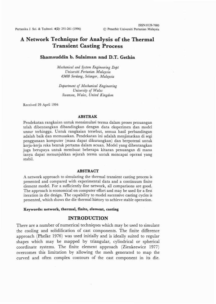
Pertanika J. Sci. & Technol. 4(2): 251-261 (1996)ISSN,OI28-7680
«:l Penerbit Universiti Pertanian Malaysia
A Network Technique for Analysis of the ThermalTransient Casting Process
ShaIJlsuddin b. SuIaiInan and D.T. Gethin
Mechanical and System Engineering DeptUniversiti Pertanian Malaysia
43400 Serdang, Selangor, Malaysia
Department of Mechanical EngineeringUniversity of Wales
Swansea~ Wales, United Kingdom
Received 29 April 1994
ABSTRAK
Pendekatan rangkaian untuk mensimulasi terma dalam proses penuangantelah dibentangkan dibandingkan dengan data eksperimen dan modelunsur terhingga. Untuk rangkaian tersebut, semua hasil perbandinganadalah baik dan memuaskan. Pendekatan ini adalah menjimatkan di segipenggunaan komputer (masa dapat dikurangkan) dan berpotensi untukkerja-kerja reka hentuk pertama dalam acuan. Model yang dibentangkanjuga berupaya untuk membuat beberapa kitaran penuangan di manaianya dapat menunjukkan sejarah terma untuk mencapai operasi yangstabi!.
ABSTRACT
A network approach to simulating the thermal transient casting process ispresented and compared with experimental data and a continuum finiteelement model. For a sufficiently fine network, all comparisons are good.The approach is economical on computer effort and may be used f?r a firstiteration in die design. The capability to model successive casting cycles ispresented, which shows the die thermal history to achieve stable operation.
Keywords: network, thermal, finite, ele:m.ent, casting
INTRODUCTIONThere are a number ofnumerical techniques which may be used to simulatethe cooling and solidification of cast components. The finite differenceapproach (Phelke 1976) was used initially and is ideally suited to regularshapes which may be mapped by triangular, cylindrical or sphericalcoordinate systems. The finite element approach (Zienkeewicz 1977)overcomes this limitation by allowing the mesh generated to map thecurved and often complex contours of the cast component in its die.
Shamsuddin b. Sulaiman and DT. Getbin
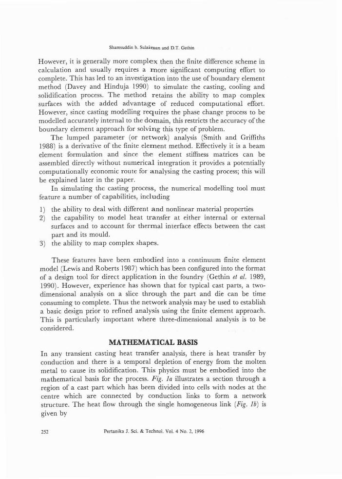
However, it is generally more complex then the finite difference scheme incalculation and usually requires a tnore significant computing effort tocomplete. This has led to an investigation into the use of boundary elementmethod (Davey and Hinduja 1990) to simulate the casting, cooling andsolidification process. The method retains the ability to map complexsurfaces with the added advantage of reduced computational effort.However, since casting modelling reg uires the phase change process to bemodelled accurately internal to the domain, this restricts the accuracy of theboundary element approach for solving this type of problem.
The lumped parameter (or network) analysis (Smith and Griffiths1988) is a derivative of the finite element method. Effectively it is a beamelement formulation and since the element stiffness matrices can beassembled directly without numerical integration it provides a potentiallycomputationally economic route for analysing the casting process; this willbe explained later in the paper.
In simulating the casting process, the numerical modelling tool mustfeature a number of capabilities, including
I) the ability to deal with different and nonlinear material properties2) the capability to model heat transfer at either internal or external
surfaces and to account for thermal interface effects between the castpart and its mould.
3) the ability to map complex shapes.
These features have been embodied into a continuum finite elementmodel (Lewis and Roberts 1987) which has been configured into the formatof a design tool for direct application in the foundry (Gethin et al. 1989,1990). However, experience has shown that for typical cast parts, a twodimensional analysis on a slice through the part and die can be timeconsuming to complete. Thus the network analysis may be used to establisha basic design prior to refined analysis using the finite element approach.This is particularly important where three-dimensional analysis is to beconsidered.
MATHEMATICAL BASIS
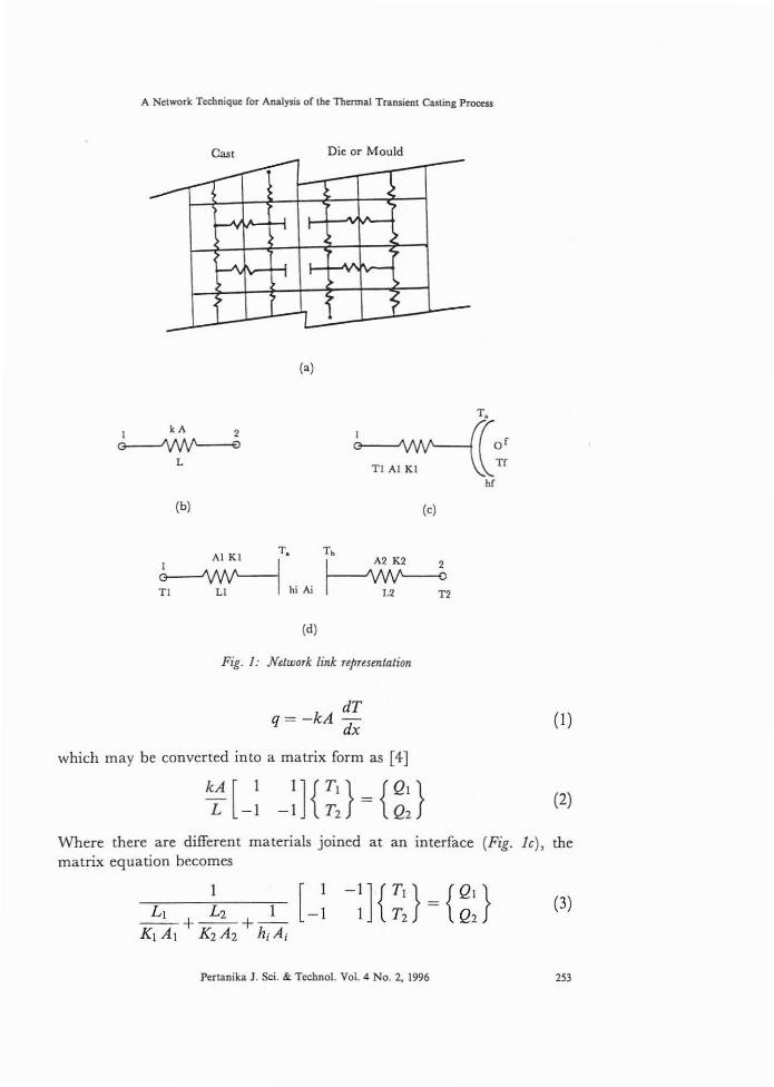
In any transient casting heat transfer analysis, there is heat transfer byconduction and there is a temporal depletion of energy from the moltenmetal to cause its solidification. This physics must be embodied into themathematical basis for the process. Fig. 1a illustrates a section through aregion of a cast part which has been divided into cells with nodes at thecentre which are connected by conduction links to form a networkstructure. The heat flow through the single homogeneous link (Fig. 1b) isgiven by
252 Pertanika J. Sci. & Techno!. Vol. 4 No.2, 1996
A Network Technique ror Analysis or lhe Thermal Transienl Casling Process
Cas. Die or Mould,----- -.------ >
• I
.A ...J• •
~
- -(a)
I It A 2
~L
(b)
Al Kl T.
~hiN(d)
(c)
To
l-A~A~I V ~2V ~
Fig. /: Network link representation
dTq= -kA
dx
which may be converted into a matrix form as [4]
(I)
(2)
Where there are different materials joined at an interface (Fig. Ie), thematrix equation becomes
1 [ 1-1] {Tr} = {Q' }
-1 1 T2 Q2(3)
Pertanika J. Sci. & Technol. Vol. 4 No.2, 1996 253
Shamsuddin b. Sulaimao and D.T. Gethio
and with heat loss to a cooling surface (Fig. Id),
(4)
In a transient analysis energy is removed from the system by conduction,and this transient energy loss per uni t volume can be expressed as
.' dTE=p e
dT
or where phase change takes place over a finite temperature interval
t- dH dT-p dT di
In discretised form, at timestep 'j' equation 5 can be expressed as
. dH [TJ+
1- T
J]E=p- I I
dT !:>'t
(5)
This can be combined with the conduction matrices (equations 2, 3 or 4) togive an appropriate transient algorithm which may be explicit, implicit orexplicit-implicit (Crank-Nicolson). For example, for an implicit formulationand a homogeneous conduction link
dH [IpV dT 0
0] _kA !:>'t [ II L -I
-I] {T~+l } = V dH {T~ }I TJ+1 P dT TJ
2 2
Similar equations may be derived by incorporating equations 3 and 4 forthe appropriate heat removal path, where in the die or mould the enthalpygradient (dB/dT) is replaced by the material specific heat. Thus for an implicit formulation, the general form of the matrix equation can be written as
Using this basis, the heat capacity matrix [C] needs to be recalculated ateach time step to account for phase change and where nonlinear thermalconductivity {k(T)} is present, the equation set needs to be solvediteratively within each step with an update of the thermal conductivity ateach iteration.
EXAMPLE CALCULATION
To test its use, the calculation procedure needs to be compared with eitherother mathematical models or experimental data, preferably both. As
254 Pertanika J. Sci. & Techno!. Vo!. 4 No.2, 1996
A Network Technique for Analysis of the Thermal Transient Casting Process
explained in Gethin et al. (1990), the continuum finite element thermaldesign tool has been compared with temperature measured on a die castingmachine. Thus this forms a convenient set of results against which thepresent model may be tested.
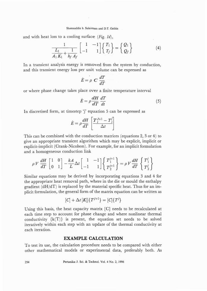
A sectional view through the cast part and die is shown in Gethin et al.(1990). This has been selected since it represents a thick section through thecasting metal injection system which will control the cooling transientduration in the cycle. The network eliscretisation for the part is shown inFig. 2. Schematically, the discretisation features homogeneous links in thedie and cast and convective links to ambient and cooling channels. Interfacelinks are used at the cast-die interface to deal with the different materials oneither side of the interface and to provide the facility to investigate the effectof pressure on the heat transfer across this gap ( ishida and Matsubora1976). The model also features grid refinement at the various interfaces; thiswas found to be necessary to achieve adequate representation of the heattransfer, particularly at the cast to die interface where thermal gradients aresteep.
(Top)
118 60 28II Channel 6
.[(Left) (Right)
::1~
~~
Channel I
l- 118 40 I 28
Fig. 2: Tlu model mesh for a section
To complete the analysis requires boundary condition specification.The following, which reflect the die casting machine operation in thefoundry, were used. For the cooling channels, a heat transfer coefficient of9000 W/m·C was used with a water temperature of 24P C while the heattransfer coefficients are small at these surfaces. Finally at die mountingsurfaces, the temperature was fixed at ISO·C. For the temporal boundary
Pertanika J, Sci. & Technol. Vol. 4 No.2, 1996 2ll
Shamsuddin b. Sulaiman and D.T. Gelhin
condition, the caSt metal was assumed to fill the die at its holding furnacetemperature of 700°C. For the first cycle simulation, the die was at auniform temperature of 150°C. During the course of calculation, a numberof cycles were simulated with the end of cycle die temperature distributionused as a starting point for the next. This cyclic calculation was continueduntil the temperature fluctuations stabilized; this will be illustrated bymeans of an example.
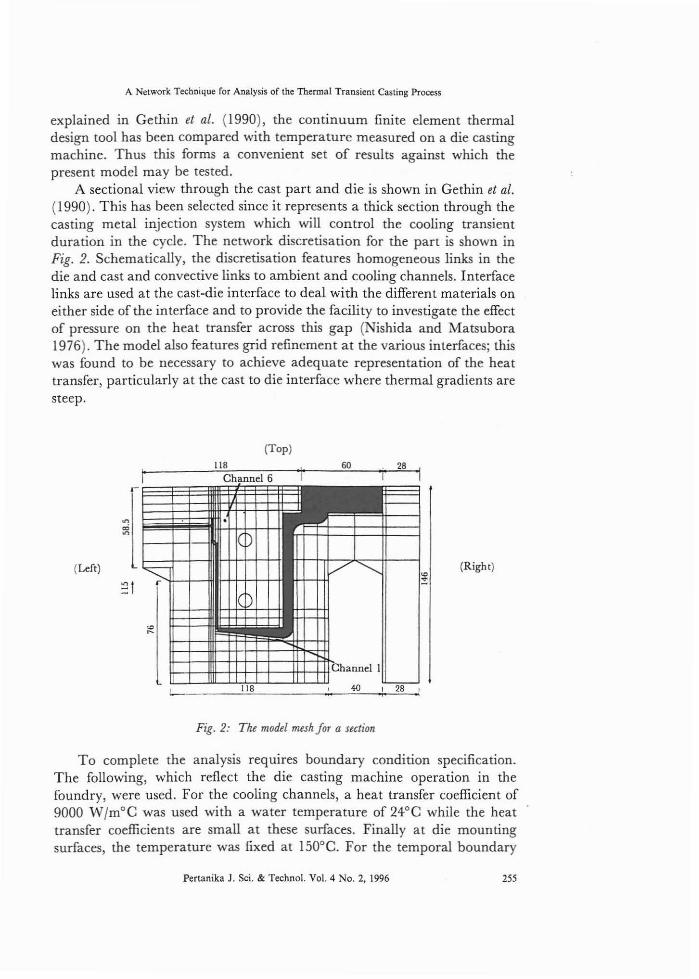
RESULTS AND DISCUSSIONFig. 3a illustrates a comparison between a thermal cycle measured in the dieat thermocouple channel I, excursions predicted suing a continuum finiteelement model (Gethin et al. 1990) and the network analysis. The networkand finite element models follow the measured excursions closely when thedie is closed, but deviate after it opens. This occurs since channel I is veryclose to the die surface and when the die opens the surface is exposed toambient conditions with a consequent rapid fall in temperature. A typicalresponse in the body of the die is shown in Fig. 3b for thermocouple ch'annel
Temperature Curves at Channel I
<a) 400
350
13~300~a~ 250
"0.
~ 200E--
150
100
(b) 260
24"
----~ .._~. __._---._.__._._-_._-
Temperature Curves at Channel 6 I--="IE220
~ 200,';:i 180ti ~~~~~.-~._.------~.---_ ••--.---
~ 160
E-- 140
----------
120
204 6 8 10 12 14 16 18
Time (sec.)
Compari.wlI IV models with experimentFig. 3:
100+----,-,.--,----.-,...---,--,...--,--,-----,o 2
256 Pertanika J. Sci. & TechnoL Vol. 4 No.2, 1996

A Network Technique for Analysis or the Thermal Transient Casting Process
6. Clearly the measured and predicted excursions are not so extreme at thislocation and the agreement between the measured and predicted response isgood. These comparisons suggest that the continuum finite element modelgives marginally better results due to its ability to model part geometrymore accurately. However, it requires a longer time to compute. Typically,the finite element analysis requires 120 min of CPU while the networkcalculation requires 10 min for a single cooling transient.
To obtain a more complete perception of the temperature responsethrough the die and cast, shaded contour plots may be prepared as shown inFig. 4a. This shows clearly the heat flow path and the area of hot moltenmetal in the thick feeding system. Further contours for the casting only areshown in Fig. 4b-d which suggest that complete solidification at atemperature of 600°C takes place by about 25 sec. This emphasizes theneed for careful design of the cooling system, particularly in the die feedingsection where the purpose of the cooling channel directly below the feedingsystem is to remove the heat rapidly and prevent premature die failure.
Thermal StabilityAs explained previously, the thermal transient calculation was completedover a number of cycles until there was a stable thermal excursionestablished in the die. This technique circumvents the problem associatedwith prescribing the correct die temperature field at the start of thetransient. Using this approach, the die is allowed to establish its ownequilibrium temperature.
Fig. 5 illustrates the thermal response at selected points in both the castpart and the die over 6 cycles of different initial and uniform dietemperatures and a casting cooling cycle time of 25 sec. Results arepresented for node 290 (which corresponds to the location of thermocouplechannel 1), node 291 which in the casting itself, but adjacent to channel I,and node 370 which represents a coolant channel. Initial uniformtemperatures considered were 50, 100, 150 and 200°C; from the results itcan be seen that the thermal excursions have stabilized in an exponentialmanner after only 6 cycles. The stable temperature depends on the startingpoint value with the most significant increase occurring for 50°C startingtemperature. This confirms the need for die heating to about 150-200°Cbefore the commencement of casting to achieve a defect-free product.
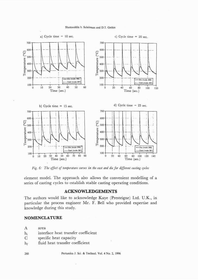
Casting Cycle TimeFig. 6 illustrates the cooling history at two points for different casting cyclefrequencies. This shows that as the cycle time is reduced, so the stabileoperating temperature become higher (Street 1986). This is a consequenceof the larger amount ofheat input into the die with the shorter casting cycletime, for the IO-sec cycle time, the stable temperature is about 350°C. This
Pertanika J. Sci. & Techno!' Vol. 4 No.2, 1996 257

....
Shamsuddin b. Sulaiman and D.T. Gethin
- -~
• .e "• "
~ ... .g &
~
~ •~ ~...;
~n
~ Ef:;
~
~ ;;;-~
.5
'b,., .'.
258 Pertartika J. Sci. & Techno!. Vol. 4 No.2, 1996

A Network Technique for Analysis of the Thermal Transient Casting Process
.' II = IjU C
~-
75 100 125 150
Time (sec.)
~
25 50
72467'
- 624~ 574- 524~ 474 ::J 424;; 374
::l. 274E 224::... 174
r- 1247424
-26o15012550 75 100
Time (sec.)
25
724f~§~§~~~~f-~~m674624
CO 574
~;: ~f==== ==- ==.'- 424= 374~ 324~ 274
E- 22' \"--_
174 ~.~ 124:- 74
2'-26
o
724F==j===r==r==f==f==]674 1--- --- ~- - ._.624 1----- -- ~---
?-' 57452'
1:: 474:;;l 424
37'~ 324
274~ 224
- ~~: ·~~I.....,I--
-26 o a ~ ~ 100 1~ 1~
Tin]!' -,',
724f==!==1==!==F=f==1674U 624 ------- -- --, --
o 574 -::--==1==:+==+==\:==\:==1524~ :~: -- u __~I: ~_r-'-? ~4 \- 324' ~--=~ _~ :;: ~-=--:::--,,~._~-~-~~-~"""=-~=S~-~-"~--:-~-"-.~'_§.~ 1U ~
r- 1~: ~E:~~24 --+--
-26o 25 50 75 100 125 150
Fig. 5: Thermal stability for different initial die temperatures
may be compared witb the stable temperature of about 250°C for the 25-seccycle time.
Computational TimeIn considering the computational aspects, the cyclic analysis presented inFig. 5 and 6 required about 55 min CPU time on a VAX 8820, whereas thecontinuum finite element analysis completed on an Apollo DN3000workstation required about 120 min CPU time to complete a singlecooling transient (Gethin et al. 1990). Thus the network approach is moreeconomical and may be used to derive an initial design for the castingsystem,
CONCLUSION
It may be concluded from this study that the network analysis provides aneconomic route for the primary design of a die or mould_ The requirementsto model interface heat transfer effects and heat removal by cooling systemsmay be incorporated readily. The results from an analysis on a simple partcompare well with experiment and with results from a continuum finite
Pertanika J. Sci. & Technol. Vol. 4 No.2, 1996 259
Shamsuddin b. Su[aiman and D.T. Gelhin
a) Cycle time = 10 sec. c) Cycle time = 20 sec.
700,---,,--,----,---.---._-,
lOO+-----i---+--i-S~~~....jo
_600()
'--"",~,~400
"c.E300~
200
10 20 30 40Time (sec.)
50 6{)
_600()
~500~
"~400~E300~
200
-- ·1 I.(.
!
b) Cycle time = 15 sec. d) Cycle time = 25 sec.
l,,i.i
700""", ,---,,---,--,,.. j ..
i600
0-~500
"B4{)0
~~300
~ 200
700.-~r----'-""---'----'------'6{)0
0-LSOO~
"400~
~300~ 200
100+---;--r-.--;~F~¥~~.o 10 20 30 40 50 00 m 00 00
Time (sec.)
100 +----i---i--i--..'==i==~~-.Jo 20 40 60 80 100 [20 140
Time (sec.)
Fig. 6: The effect oj temperature curves in the cast and die Jor diffutllt casting cycles
element model. The approach also allows the convenient modelling of aseries of casting cycles to establish stable casting operating conditions.
ACKNOWLEDGEMENTS
The authors would like to acknowledge Kaye (Presteigne) Ltd. U.K., inparticular the process engineer Mr. F. Bell who provided expertise andknowledge during this study.
NOMENCLATURE
A areahi interface heat transfer coefficientC specific heat capacityhe fluid heat transfer coefficient
260 Pertanika 1. Sci. & Technol. Vol. 4 No.2, 1996
A Network Technique (or Analysis o( the Thermal Transient Casting Process
H enthalpyk thermal conductivityL lengtht timeT temperaturep densityV volume
REFERENCESDAVEY, K. and S. HINDUJA. 1990. Modelling the pressure die casting process with the
boundary element method, steady state approximation. I]NME, p1275.
GETHIN, D.T., R.W. LEWIS and D.V. TRAN. 1989. Computer based tools for thefoundry industry. In ProfConf Numerical Methods in Thermal Problems, Vol. VI, ed.Lewis and Morgan, p254-266.
GETHIN, D.T, R.W. LEWIS and D.V TRAN. 1990. A finite element approach for diethermal design in high pressure die casting and its experimental verification. CastMe/als 3: 149-156.
LEWIS, R.W. and P.M. ROBERTS. 1987. Finite element simulation of solidificationproblems. Applied Scientific Research 44: GI-92.
NISHIDA, Y. and H. MATSUBORA. 1976. Effect of pressure on heat transfer at themetal mould-casting interface British Foundryman 69: 274-278.
PHELKE, R.D., R.E. MARRONE and J.D. WILKES. 1976. Computer Simulation ofSolidification. American Foundryman Society.
SMITH, I.M. and D.V. GRIFFITHS. 1988. Programming the Finite Element Method, 2ndedn. London: Wiley.
STREET, A.C. 1986. The Diecasting Book, 2nd edn. Portcullis Press.
ZIENKEEWICZ, D.C. 1977. The Finite Element Method. McGraw Hill.
Pertanika J. Sci. & Techno!' Vol. 4 No.2, 1996 261