Embed Size (px)
Citation preview
Behavior Research Methods& Instrumentation1979, Vol. 11 (2), 293-300
SESSION XIIMICROCOMPUTER-BASED LABORATORIES II
A. M. LESGOLD, University ofPittsburgh, Presider
A microcomputer-controlled laboratory:Hardware
RICHARD F. DILLON, BARRY MILLMAN, JO W. TOMBAUGH,WILLIAM R. FERGUSON, and WILLIAM R. BEZANSON
Carleton University, Ottawa K1S 5B6, Canada
A microcomputer-controlled laboratory designed to incorporate the Motorola 6800 microprocessor unit is described. The microcomputer system is reliable, flexible, and expandable,as well as adaptable to the next generation of Motorola microprocessor components. A modularsystem design utilizes multiprocessing with separate microprocessor units dedicated to specificfunctions. This computer, when used with powerful, high-level software, provides a generalpurpose psychology laboratory computer system that is easy to use.
In this and a following paper (Tombaugh, Dillon,Millman, & Bezanson, 1979), a large project to developan easy-to-use and flexible microcomputer systemadaptable to many laboratory settings is described.Thisproject was designed and implemented by a team consisting of a systems engineer specializing in real-timeapplications, an electronic technologist experienced indesign of microcomputer systems, and three psychologists who have previously developed laboratory computer system software including high-level languages(Dillon, Dumontier, Bezanson, & Brennan, 1978;Tombaugh, 1974; Millman, Note 1). This team wasrecruited at the request of physiological psychologistsin our department who realized the advantages of aflexible microcomputer system if the programmingproblem could be minimized. The team developed thehardware configuration described in this paper anddesigned and programmed software to make the systemeasy to use (Tombaugh et aI., 1979).
SELECTING A MICROCOMPUTER
The Decision to Build or to BuyThe sensational prices quoted for microprocessors,
This research was supported by NRC grants to W. E. Websterand Brian Tansley, and a grant from the Department of Psychology. Time on the central Carleton University computer wasprovided by a grant from the President's Computer Fund.G. Crichlow and D. Parlour contributed to a varietyof phases of the project. N. Mikhail was instrumentalin the design and fabrication of many of the prototype modulesdescribed in this paper. Complete plans for the hardware described in this paper and unpopulated printed circuit boards areavailable at nominal cost. Barry Millman is now at Data Kinetics,Ottawa, Canada. Requests for reprints should be addressed toRichard F. Dillon, Department of Psychology, Carleton University, Ottawa, Ontario KIS 5B6. Canada.
often less than $100, are misleading since the microprocessorunit (MPU) must be accompaniedby a numberof components to produce a computer. Our first decision was whether to buy or to build a computer. Unfortunately, the systems commercially available in early1978 failed to meet a number of important requirements.
The first problem was price. Microcomputers appropriate for laboratory use were available, but at aprice that exceeded the projected budget. Affordablecomputers were oriented primarily at the hobbyist. Thesecond problem was that we wanted a system thatcould easily be interfaced to a large number of peripheral devices and could be easilyexpanded. Because of anapparent emphasis on small size, most commerciallyavailable microcomputers in the desired price range werelimited in this respect. Third, high-quality peripheraldevices-fellable and capable of withstanding heavyuse-were needed. The hobby computers had limitedperipherals of an unknown quality. The prospect ofbuying a cassette-based system, or even a minifloppydisk system, from an unknown company was not appealing. Fourth, a structured high-level language wasrequiredfor writing system software. BASIC, the dominantlanguage in the hobby-computer field, is not an adequatesystems language. Finally, it was not clear whether thecommercial computers were designed to incorporatethe next generation of microprocessors. With microprocessor technology advancing so rapidly, care must betaken to avoid equally rapid obsolescence. In view ofthese factors, the decision was made to use the expertiseavailable on campus to design and fabricate a modularmicrocomputer system of industrial quality at a hobby.computer price.
Microprocessor UnitOnce the decision to design a computer system was
Copyright 1979 Psychonomic Society, Inc. 293 0005-7878/79/020293-08$01.05/0
294 DILLON, MILLMAN, TOMBAUGH, FERGUSON, AND BEZANSON
made, attention was focused on the choice of the mostappropriate microprocessor unit. This decision was madeon the basis of a number of criteria. First, cost (a totalbudget of less than $8,000 for MPU, design costs, andperipherals) ruled out the most popular 16-bit MPUs.Second, although it was known that the three majormanufacturers were planning to introduce secondgeneration MPUs, a decision was made to start development immediately using a MPU and support componentsthat were readily available. Third, it was known in early1978 that at least one manufacturer (Motorola) intendedto introduce a second-generation MPU that would behardware and software compatible with their existingMPU (Wiles, Musa, Ritter, Boney, & Gunter, 1978).We hoped to design a system around a MPU that couldeasily be replaced when the next generation becameavailable and could use our software with minimummodification. Fourth, the plan was to start programmingbefore the hardware was available. For this reason, ahigh-level cross-compiler, cross-assembler, and simulatorwere needed. Finally, a disk controller and interface anda convenient operating system were essential. It was notour intention to build the controller or to write theoperating system. Consideration was given only to MPUsfor which such hardware and software were availablecommercially.
Taking these criteria into consideration, the Motorola'M6800 MPU was selected. This MPU uses a straightforward hardware approach and has a convenient instruction set.
MICROCOMPUTER SYSTEM CONFIGURAnON
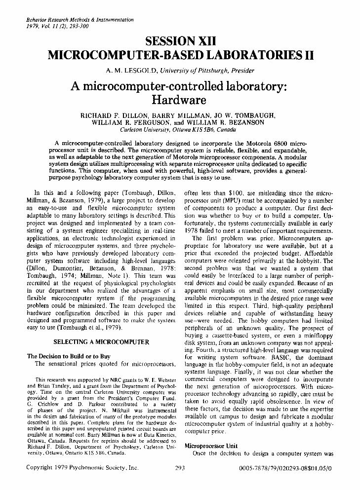
A block diagram of the system is shown in Figure 1.At this stage, the system is fairly conventional. Themodules and devices shown in Figure 1 provide maximum flexibility and reliability. In general, if highquality modules were available at a reasonable price,they were purchased; if not, we designed our own.
Prototype versions of a number of our boards areillustrated in Figures 2-5. All modules have been testedand functioning for some time. Production versionswill use high-quality printed circuit boards with platedthrough holes and gold-plated contacts for maximumreliability. Individual boards were designed to providemaximum possible address flexibility, although oursoftware attempts to use Southwest Technical Products? address conventions whenever possible.
Our design philosophy is to isolate functions onindividual boards. Densely populated modules achievesmall size at the expense of complexity. Avoidingmultifunction boards facilitates hardware testing,maintenance, and troubleshooting.
Mother Board, Card Cage, and ChassisThe modules shown at the left of Figure I reside in
a rack-mounted chassis with the front removable to
Figure 1. System block diagram.
provide easy access to all boards. A 19-s10t motherboard and card cage, shown in Figure 6, fit into thechassis. The card cage is 48.3 em wide, 13.3 em high,and 33.1 em deep. The mother board provides access tothe Motorola Exorciser bus, a convenient 86-pin connector bidirectional bus, at each slot. Since all addressesare provided to all slots, the maximum possible combination of random-access memory (RAM), eraseable programmable read-only memory (EPROM), and specialfunction addresses is 65,000 bytes.
Power SupplyA Lambda" triple-power supply provides 5 V at
12 A, and ±12 V at 3 A. The power supply is rackmounted on a separate panel above the computerchassis.
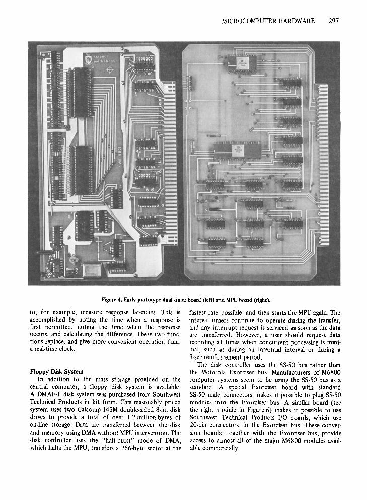
Master 6800 MPUThe MPU with clock circuitry, data and address
buffering, and direct memory access (DMA) circuitryis shown at the right in Figure 4. The 6800 A versionMPU functions at a 1.5-MHz clock rate. Consistentwith our desire to isolate functions on individualmodules, there are no other functions on the MPUboard, although there is a 128-byte RAM, convenientfor testing the board, which is disabled for normaloperation.
RAMRAM in 8-kilobyte modules, was purchased from
Creative Microsystems." This static memory with2S0-nsec access time is switch selectable in 8-kilobyteblocks. Typically, three to six RAM modules are used,although modules can be added or removed as needed.
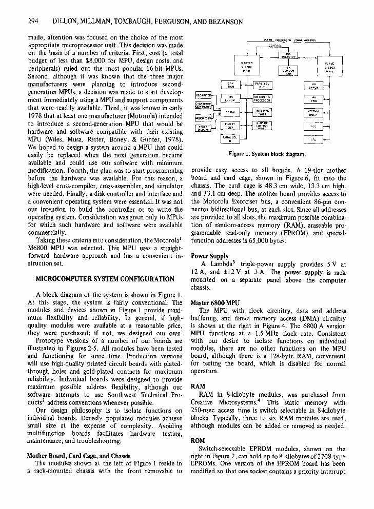
ROMSwitch-selectable EPROM modules, shown on the
right in Figure 2, can hold up to 8 kilobytes of2708-typeEPROMs. One version of the EPROM board has beenmodified so that one socket contains a priority interrupt
MICROCOMPUTER HARDWARE 295
Figure 2. Optically isolated parallel I/O board (left) and EPROM board (right).
controller, which provides eight vectored interrupts.Among other programs, one EPROM board contains
a monitor. At various times Motorola's Mikbug, Microware's RT/68,s and Southwest Technical Products'SWTbug and Diskbug monitors have been used. EPROMsare programmed using hardware and software that wedeveloped. The very inexpensive Southwest TechnicalProducts' EPROM programmer has also been satisfactory.
Parallel Input-OutputAn optically isolated input-output (I/O) board,
shown at the left in Figure 2, is populated with oneperipheral interface adapter (PIA) to provide 20 bits ofprogrammable parallel I/O. The optically isolatedparallel board is used for control with input and outputdevices (lights, tones, shock sources, solenoids, responselevers) that are outside the computer chassis. In electrically noisy environments, lines connecting suchdevices to the computer are doubly isolated at thecomputer and at the device. Twenty buttons and switches,interfaced through a 20-position keyboard encoder, useone of these boards. The encoder provides a unique
5-bit binary signal for each button, so all 20 buttonsuse the same PIA. Examination of the bit patternindicates which button was pressed.
The block labeled "runtime control panel" inFigure 1 uses five of these parallel input buttons. Thefunction of each of these special-purpose buttonsin our run-time system is described in Table I.
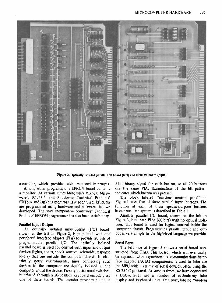
Another parallel I/O board, shown on the left inFigure 3, has three PIAs (60 bits) with no optical isolation. This board is used for logical control inside thecomputer chassis. Programming parallel input and output is very simple in the high-level language we provide.
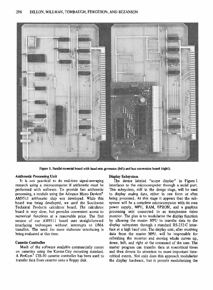
Serial PortsThe left side of Figure 5 shows a serial board con
structed from PIAs. This board, which will eventuallybe replaced with asynchronous communications interface adapter (ACIA) components, is used to interfacethe MPU with a variety of serial devices, often using theRS-232-C protocol. At various times, we have connecteda DECwriter II and a number of cathode-ray tubedisplay and keyboard units. One port, labeled "modem
296 DILLON, MILLMAN, TOMBAUGH, FERGUSON, AND BEZANSON
Figure 3. Nonoptically isolated parallel I/O board (left) and dual-function timer board (right).
Switch Label
NEXT AVERAGE
EXCLUDE DATA
START
RESTART
STOP
Table IConsole Switches and Their Functions in a
Signal-Averaging Experiment
Function
This switch is used to start an experiment.
This switch results in all parametersbeing reset to the values that they hadwhen START was first pressed. Usefulto check electrodes, etc., before startingactual run.
Data currently displayed on displaysystem will not be recorded on disk.Used to reject "noisy" data.
A researcher programs some number oftrials to be included in an average.This button overrides the predeterminednumber.
This button terminates the experimentalsession.
to Sigma 9" in Figure I, is connected to an acousticcoupler that provides access to an extremely usefulperipheral device, the central campus computer. Weattempt to dedicate the laboratory computer to runningexperiments and perform as many functions as possibleon the central computer.
Interval TimersFigure 3 shows a multiple-function timer (on the
right), which provides sophisticated timing capabilities.An interval timer function is programmed by storing2 consecutive bytes containing the desired interval at thetimer address. The timer sends an interrupt to the MPUwhen the interval is complete. The second functiondoes not interrupt the MPU. The time from the startof an experiment can be determined by loading anaccumulator with the contents of the addresses used bythis function. The interval timer is used to controlpredetermined intervals; the interrogation timer is used
MICROCOMPUTER HARDWARE 297
Figure 4. Early prototype dual timer board (left) and MPU board (right).
to, for example, measure response latencies. This isaccomplished by noting the time when a response isfirst permitted, noting the time when the responseoccurs, and calculating the difference. These two functions replace, and give more convenient operation than,a real-time clock.
Floppy Disk SystemIn addition to the mass storage provided on the
central computer, a floppy disk system is available.A DMAF-l disk system was purchased from SouthwestTechnical Products in kit form. This reasonably pricedsystem uses two Calcomp 143M double-sided 8-in. diskdrives to provide a total of over 1.2 million bytes ofon-line storage. Data are transferred between the diskand memory using DMA without MPU intervention. Thedisk confroller uses the "halt-burst" mode of DMA,which halts the MPU, transfers a 256-byte sector at the
fastest rate possible, and then starts the MPU again. Theinterval timers continue to operate during the transfer,and any interrupt request is serviced as soon as the dataare transferred. However, a user should request datarecording at times when concurrent processing is minimal, such as during an intertrial interval or during a3-sec reinforcement period.
The disk controller uses the 88-50 bus rather thanthe Motorola Exorciser bus. Manufacturers of M6800computer systems seem to be using the 88-50 bus as astandard. A special Exorciser board with standardSS-50 male connectors makes it possible to plug 55-50modules into the Exorciser bus. A similar board (seethe right module in Figure 6) makes it possible to useSouthwest Technical Products I/O boards, which use20-pin connectors, in the Exorciser bus. These conversion boards, together with the Exorciser bus, provideaccess to almost all of the major M6800 modules available commercially.
298 DILLON, MILLMAN, TOMBAUGH, FERGUSON, AND BEZANSON
Figure 5. Parallel-to-serial board with baud-rate generator (left) and bus conversion board (right).
Arithmetic Processing UnitIt is not practical to do real-time signal-averaging
research using a microcomputer if arithmetic must beperformed with software. To provide fast arithmeticprocessing, a module using the Advance Micro Devices"AM9511 arithmetic chip was developed. While thisboard was being developed, we used the SouthwestTechnical Products calculator board. The calculatorboard is very slow, but provides convenient access tonumerical functions at a reasonable price. The firstversion of our AM9511 board uses straightforwardinterfacing techniques without interrupts or DMAtransfers. The need for more elaborate interfacing isbeing evaluated at this time.
Cassette ControllerMuch of the software available commercially comes
on cassettes using the Kansas City recording standard.A Per(om7 CIS-30 cassette controller has been used totransfer data from cassette onto a floppy disk.
Display SubsystemThe device labeled "scope display" in Figure I
interfaces to the microcomputer through a serial port.This subsystem, still in the design stage, will be usedto display analog data, either in raw form or afterbeing processed. At this stage it appears that the subsystem will be a complete microcomputer with its ownpower supply, MPU, RAM, EPROM, and a graphicsprocessing unit connected to an inexpensive videomonitor. The plan is to modularize the display functionby allowing the master MPU to transfer data to thedisplay subsystem through a standard RS-232-C interface at a high baud rate. The display unit, after receivingdata from the master MPU, will be responsible forrefreshing the monitor and moving whole curves up,down, left, and right at the command of the user. Themaster program can transfer data at noncritical timesand then devote its attention to more important timecritical events. Not only does this approach modularizethe display hardware, but it permits modularizing the
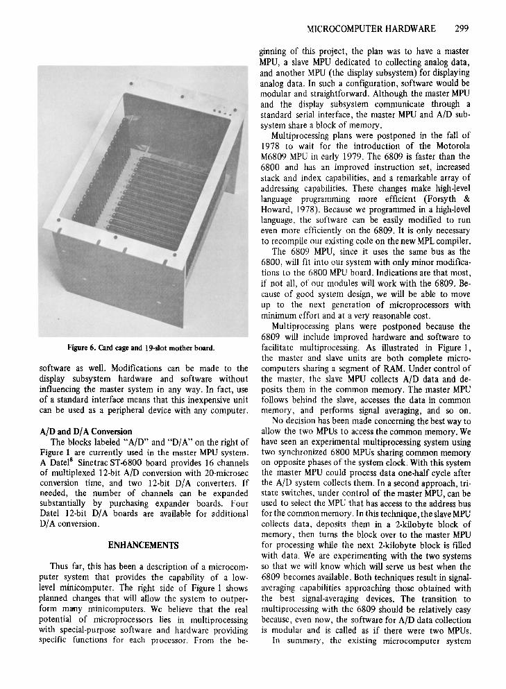
Figure 6. Card cage and 19-s1ot mother board.
software as well. Modifications can be made to thedisplay subsystem hardware and software withoutinfluencing the master system in any way. In fact, useof a standard interface means that this inexpensive unitcan be used as a peripheral device with any computer.
AID and DIA ConversionThe blocks labeled "A/D" and "DIA" on the right of
Figure 1 are currently used in the master MPU system.A Datel8 Sinetrac ST-6800 board provides 16 channelsof multiplexed 12-bit AID conversion with 20-microsecconversion time, and two 12-bit DIA converters. Ifneeded, the number of channels can be expandedsubstantially by purchasing expander boards. FourDatel 12-bit D/A boards are available for additionalDIA conversion.
ENHANCEMENTS
Thus far, this has been a description of a microcomputer system that provides the capability of a lowlevel minicomputer. The right side of Figure I showsplanned changes that will allow the system to outperform many minicomputers. We believe that the realpotential of microprocessors lies in multiprocessingwith special-purpose software and hardware providingspecific functions for each processor. From the be-
MICROCOMPUTER HARDWARE 299
ginning of this project, the plan was to have a masterMPU, a slave MPU dedicated to collecting analog data,and another MPU (the display subsystem) for displayinganalog data. In such a configuration, software would bemodular and straightforward. Although the master MPUand the display subsystem communicate through astandard serial interface, the master MPU and A/D subsystem share a block of memory.
Multiprocessing plans were postponed in the fall of1978 to wait for the introduction of the MotorolaM6809 MPU in early 1979. The 6809 is faster than the6800 and has an improved instruction set, increasedstack and index capabilities, and a remarkable array ofaddressing capabilities. These changes make high-levellanguage programming more efficient (Forsyth &Howard, 1978). Because we programmed in a high-levellanguage, the software can be easily modified to runeven more efficiently on the 6809. It is only necessaryto recompile our existing code on the new MPLcompiler.
The 6809 MPU, since it uses the same bus as the6800, will fit into our system with only minor modifications to the 6800 MPU board. Indications are that most,if not all, of our modules will work with the 6809. Because of good system design, we will be able to moveup to the next generation of microprocessors withminimum effort and at a very reasonable cost.
Multiprocessing plans were postponed because the6809 will include improved hardware and software tofacilitate multiprocessing. As illustrated in Figure I,the master and slave units are both complete microcomputers sharing a segment of RAM. Under control ofthe master, the slave MPU collects A/D data and deposits them in the common memory. The master MPUfollows behind the slave, accesses the data in commonmemory, and performs signal averaging, and so on.
No decision has been made concerning the best way toallow the two MPUs to access the common memory. Wehave seen an experimental multiprocessing system usingtwo synchronized 6800 MPUs sharing common memoryon opposite phases of the system clock. With this systemthe master MPU could process data one-half cycle afterthe A/D system collects them. In a second approach, tristate switches, under control of the master MPU, can beused to select the MPU that has access to the address busfor the common memory. In this technique, the slaveMPUcollects data, deposits them in a 2-kilobyte block ofmemory, then turns the block over to the master MPUfor processing while the next 2-kilobyte block is filledwith data. We are experimenting with the two systemsso that we will know which will serve us best when the6809 becomes available. Both techniques result in signalaveraging capabilities approaching those obtained withthe best signal-averaging devices. The transition tomultiprocessing with the 6809 should be relatively easybecause, even now, the software for AID data collectionis modular and is called as if there were two MPUs.
In summary, the existing microcomputer system
300 DILLON, MILLMAN, TOMBAUGH, FERGUSON, AND BEZANSON
provides a reliable solution to many laboratory controlproblems. With our high-level language, and with theaddition of multiprocessing using the next generation6809 microprocessors, we will have a system with theunique combination of power and ease of use.
REFERENCE NOTE
I. Millman, B. PSYPAL: A computer language for the controlor psychological experiments. Calgary, Alberta: University ofCalgary, Department of Psychology Technical Report. 1971.
REFERENCES
DILLON, R. F., DUMONTJER, L. R., BEZANSON, W. R., &BRENNAN, R. A high-level language for control of psychologyexperiments. Behavior Research Methods & Instrumentation,147/l, 10, 315-324.
FORSYTH, C. H., & HOWARD, R. J. Compilation and PASCALon the new microprocessors. Byte, April 1978, pp. 50-61.
TOM BAUGH, J. W. A user's language and operating system forbehavioral research. Proceedings o] the Digital EquipmentCorporation Users' Society, Ottawa, Canada, 1974.
TOMBAUGH,1. W. o DIllON, R. F., MILLMAN, B., & BEZANSON,
W. R. A microcomputer-controlled laboratory: Software.Behavior Research Methods & Instrumentation, 1979, 11,301-310.
WILES, Moo MUSA, F., RITTER, T. F., BONEY, 1., & GUNTER, T.Compatibility cures growing pains of microcomputer family.Electronics, 1978,51(3),95-103.
NOTES
1. Motorola Semiconductor Products, Inc., Box 20912,Phoenix, Arizona 85036.
2. Southwest Technical Products Corporation, 219 WestRhapsody, San Antonio, Texas 78216.
3. Lambda Electronics, 515 Broad Hollow Road, Melville,New York 11746.
4. Creative Micro Systems, 6773 Westminster Avenue,Westminster, California 92683.
5 Microware Systems Corporation, P. O. Box 954, DesMoines, Iowa 50304.
6. Advanced Micro Devices, 901 Thompson Place, Sunnyvale,California 94036.
7. PerCom Data Company, Inc., Department B, 310 Barnes,Garland, Texas 75042.
8. Datel Systems, Inc., 1020 Turnpike Street, Canton,Massachusetts 02021.

![Untitled-1 []_manual.pdf · This unit implements microcomputer controlled ... BASIC INSTRUCTIONS: I : ... Heating Element area 120mm x 120 mm](https://img.dokumen.tips/doc/110x75/5b276abb7f8b9a4b7e8b6980/untitled-1-manualpdf-this-unit-implements-microcomputer-controlled-.jpg)